My Haas Welcome,
!
Haas Tooling MyHaas/HaasConnect Sign In Register Haas Tooling MyHaas/HaasConnect Sign Out Welcome, My Machines Latest Activity My Quotes My Account My Users Sign Out
Find Your Distributor
  1. Select Language
    1. English
    2. Deutsch
    3. Español - ES
    4. Español - MX
    5. Français
    6. Italiano
    7. Português
    8. Český
    9. Dansk
    10. Nederlands
    11. Magyar
    12. Polski
    13. Svenska
    14. Türkçe
    15. 中文
    16. Suomi
    17. Norsk
    18. الإنجليزية
    19. български
    20. Hrvatski
    21. Ελληνικά
    22. Română
    23. Slovenský
    24. Slovenščina
    25. 한국어
    26. 日本語
    27. Українська
  • machines Main Menu
    • Vertical Mills
      Vertical Mills
      Vertical Mills View All
      • Vertical Mills
      • VF Series
      • Universal Machines
      • VR Series
      • VP-5 Prismatic
      • Pallet-Changing VMCs
      • Mini Mills
      • Mold Machines
      • High-Speed Drill Centers
      • Drill/Tap/ Mill Series
      • Toolroom Mills
      • Pocket Mill
      • Compact Mills
      • Gantry Series
      • SR Sheet Routers
      • Extra-Large VMC
      • Double-Column Mills
      • 3+2 Positioning Machines
    • Multi-Axis Solutions
      Multi-Axis Solutions
      Multi-Axis Solutions View All
      • Multi-Axis Solutions
      • Y-Axis Lathes
      • 5-Axis Mills
    • Lathes
      Lathes
      Lathes View All
      • Lathes
      • ST Series
      • Dual-Spindle
      • Box Way Series
      • Toolroom Lathes
      • Chucker Lathe
      • Pocket Lathe
      • Haas Bar Feeders
    • Horizontal Mills
      Horizontal Mills
      Horizontal Mills View All
      • Horizontal Mills
      • 50-Taper
      • 40-Taper
    • Rotaries & Indexers
      Rotaries & Indexers
      Rotaries & Indexers View All
      • Rotaries & Indexers
      • Rotary Tables
      • Indexers
      • 5-Axis Rotaries
      • Extra-Large Rotaries
    • Special Series
      Special Series
      Special Series View All
      • Special Series
      • EU_Series_Redirect
    • Automation Systems
      Automation Systems
      Automation Systems View All
      • Automation Systems
      • Mill Automation
      • Lathe Automation
      • Automatic Parts Loaders
      • Automation Models
    • Desktop Machines
      Desktop Machines
      Desktop Machines View All
      • Desktop Machines
      • Desktop Mill
      • Desktop Lathe
      • Control Simulator, Standard
      • Control Simulator, Premium
    • Shop Equipment
      Shop Equipment
      Shop Equipment View All
      • Shop Equipment
      • Knee Mill
      • Haas Manual Lathes
      • Haas Saws
    • Fabrication Machines
      Fabrication Machines
      Fabrication Machines View All
      • Fabrication Machines
      • Laser Cutting Machines
      • CNC Press Brakes
    • QUICK LINKS Special Series  Special Series 
      EU SERIES EU SERIES BUILD & PRICE | PRICE LIST BUILD & PRICE | PRICE LIST In-Stock Machines In-Stock Machines WHAT’S NEW WHAT’S NEW YOUR FIRST CNC YOUR FIRST CNC
      SHOPPING TOOLS
      • Build & Price a Haas
      • Price List
      • Available Inventory
      • CNCA Financing
      WANT TO TALK TO SOMEONE?

      A Haas Factory Outlet (HFO) can answer your questions, and walk you through your best options.

      CONTACT YOUR DISTRIBUTOR >
  • Options Main Menu
    • The Haas Control Value Option Packages
      Value Option Packages
      Value Option Packages View All
      • Value Option Packages
    • Product Image Spindles
      Spindles
      Spindles View All
      • Spindles
    • Product Image Tool Changers
      Tool Changers
      Tool Changers View All
      • Tool Changers
    • Product Image 4th- | 5th-Axis
      4th- | 5th-Axis
      4th- | 5th-Axis View All
      • 4th- | 5th-Axis
    • Product Image Turrets & Live Tooling
      Turrets & Live Tooling
      Turrets & Live Tooling View All
      • Turrets & Live Tooling
    • Product Image Probing
      Probing
      Probing View All
      • Probing
    • Haas Chip & Coolant Management Chip & Coolant Management
      Chip & Coolant Management
      Chip & Coolant Management View All
      • Chip & Coolant Management
    • The Haas Control The Haas Control
      The Haas Control
      The Haas Control View All
      • The Haas Control
    • Product Image Product Options
      Product Options
      Product Options View All
      • Product Options
    • Product Image Tooling & Fixturing
      Tooling & Fixturing
      Tooling & Fixturing View All
      • Tooling & Fixturing
    • Product Image Workholding
      Workholding
      Workholding View All
      • Workholding
    • Product Image 5-Axis Solutions
      5-Axis Solutions
      5-Axis Solutions View All
      • 5-Axis Solutions
      • 5 Easy Steps to 5-Axis
    • QUICK LINKS Special Series  Special Series 
      EU SERIES EU SERIES BUILD & PRICE | PRICE LIST BUILD & PRICE | PRICE LIST In-Stock Machines In-Stock Machines WHAT’S NEW WHAT’S NEW YOUR FIRST CNC YOUR FIRST CNC
      SHOPPING TOOLS
      • Build & Price a Haas
      • Price List
      • Available Inventory
      • CNCA Financing
      WANT TO TALK TO SOMEONE?

      A Haas Factory Outlet (HFO) can answer your questions, and walk you through your best options.

      CONTACT YOUR DISTRIBUTOR >
  • Why Haas Main Menu
      Discover the Haas Difference
    • Why Haas
    • MyHaas
    • Education Community
    • Industry 4.0
    • Haas Certification
    • Customer Testimonials
  • Service Main Menu
      Welcome to Haas Service
      SERVICE HOME Operator’s Manuals How-To Procedures Troubleshooting Guides Preventive Maintenance Haas Parts Haas Tooling Videos
  • Videos Main Menu
  • Main Menu
    • View All
    • View All
    • View All
    • View All
      • HTEC Curriculum Support
      • Haas Value Option Packages (VOP) Journey
    • View All
      • Haas 10 kg Cobot Package
      • Cobot Kits
      • DC-1 Drill Center
      • CNC Sales News
      • Do More With Your Haas
    • View All
    • View All
      • contact-us-test
      • 4 - AUTOMATION SYSTEMS
      • Carousel-V2
      • expert test
      • Demo_Day_Trident-test
      • Link Test
      • image-sale-tag-test
      • article-list-test
      • Haas 25 kg Robot Package
      • test-algolia-page
    • View All
    • View All
    • View All
    • View All
      • calc-test
    • View All
    • QUICK LINKS Special Series  Special Series 
      EU SERIES EU SERIES BUILD & PRICE | PRICE LIST BUILD & PRICE | PRICE LIST In-Stock Machines In-Stock Machines WHAT’S NEW WHAT’S NEW YOUR FIRST CNC YOUR FIRST CNC
      SHOPPING TOOLS
      • Build & Price a Haas
      • Price List
      • Available Inventory
      • CNCA Financing
      WANT TO TALK TO SOMEONE?

      A Haas Factory Outlet (HFO) can answer your questions, and walk you through your best options.

      CONTACT YOUR DISTRIBUTOR >
  • Haas Tooling Main Menu
  • Haas Service Parts Main Menu

My Haas Welcome,
!
Haas Tooling MyHaas/HaasConnect Sign In Register Haas Tooling MyHaas/HaasConnect Sign Out Welcome, My Machines Latest Activity My Quotes My Account My Users Sign Out
Find Your Distributor
  1. Select Language
    1. English
    2. Deutsch
    3. Español - ES
    4. Español - MX
    5. Français
    6. Italiano
    7. Português
    8. Český
    9. Dansk
    10. Nederlands
    11. Magyar
    12. Polski
    13. Svenska
    14. Türkçe
    15. 中文
    16. Suomi
    17. Norsk
    18. الإنجليزية
    19. български
    20. Hrvatski
    21. Ελληνικά
    22. Română
    23. Slovenský
    24. Slovenščina
    25. 한국어
    26. 日本語
    27. Українська
×

Search Results

Web Pages

Images

    • <
    • 1
    • >

4 - HBF - 12 - Installation

Haas Bar Feeder 12 - Operator's / Service Manual


  • 0 - HBF - 12 - Table of Contents
  • 1 - HBF - 12 - Introduction
  • 2 - HBF - 12 - Legal Information
  • 3 - HBF - 12 - Safety
  • 4 - HBF - 12 - Installation
  • 5 - HBF - 12 - Operation
  • 6 - HBF - 12 - Maintenance
  • 7 - HBF - 12 - Troubleshooting

Go To :

Recently Viewed Items

You Have No Recently Viewed Items Yet

  • 4.1 HBF - 12 - Installation
  • 4.2 Pushrod, Channels, and Liner Installation
  • 4.3 HBF - 12 - Conduit Retention Panel Retrofit

4.1 HBF - 12 - Installation

Recently Updated

HBF - 12 - Installation


Revision D - 06/2026

Introduction

Updated

HBF-12 required pre-installation kits:

  • 93-1000313 8 SPARE M FUNCTIONS - NGC / OR / 93-3319 8M FI KIT W/ HINGE DOOR 
  • 93-5581 ENCL CABLE COVER LR KIT ST-10/20/30/40/Y (Refer to Conduit Retention Panel Retrofit tab for more information) 

Note : 93-5581 is not required if lathe is ordered with HBF12.


Required tools :

  • Nylon string
  • Hammer drill with 5/8" drill bit
  • Machined pucks
  • Mallet
  • Spring caliper (ID)
  • Collet chuck
  • Tape measure

Note : The machined pucks ensure the string is centered and concentric to the collet chuck. It is recommended to use this alignment method to avoid high rpm vibrations.

Additional kits for operation (Required) :

  • Refer to Installation kit guide table below.

Machine Compatibility :

  • ST-10/15/20/25/30 after 06/2017 (Equipped with NGC)
  • DS-20/25/30 after 06/2017 (Equipped with NGC)

Oil Type (Requires 11.75 gal (44L)) :

  • PN : 93-5656: OIL, 1 GALLON ISO 68

Note : This also applies to L/Y/LY variants of the machines listed above.

Note: The Macros option must be enabled to run this procedure. This is a paid option and may not be installed on all machines. To verify if Macros is enabled, go to Parameters > Features and confirm that Macros is selected. If Macros is not enabled, refer to How to Enter Option Codes – AD0932 for instructions on loading option codes.

Note : It is recommended to use the Haas Fastener Torque Specifications

Installation Kit Guide

Updated

If you would like to order a tooling kit, please visit Bar Feeder 12 Tooling kits for more information and purchasing options.

Haas Tooling Kit* Stock Size Range**
ST-10, 1.75" Stock Capacity/Drawbar Size
08-2110 20MM\0.787" 12FT BF KIT 1.75" INCH 0.375" - 0.625"
08-2111 20MM\0.787" 12FT BF KIT 1.75" METRIC 10.0 mm - 16.0 mm
08-2112 26MM\1.024" 12FT BF KIT 1.75" INCH 0.75" - 0.825"
08-2113 26MM\1.024" 12FT BF KIT 1.75" METRIC 17.0 mm - 20.0 mm
08-2114 34MM\1.339" 12FT BF KIT 1.75" INCH 1" - 1.125"
08-2115 34MM\1.339" 12FT BF KIT 1.75" METRIC 25.0 mm - 30.0 mm
08-2116 38MM\1.496" 12FT BF KIT 1.75" INCH 1.25" - 1.375"
08-2117 38MM\1.496" 12FT BF KIT 1.75" METRIC 32.0 mm - 35.0 mm
ST-15/20 &DS-20Y, 2.5" Stock Capacity/Drawbar Size
08-2118 20MM\0.787" 12FT BF KIT 2.5" INCH 0.375" - 0.625"
08-2119 20MM\0.787" 12FT BF KIT 2.5" METRIC 10.0 mm - 16.0 mm
08-2120 26MM\1.024" 12FT BF KIT 2.5" INCH 0.75" - 0.825"
08-2121 26MM\1.024" 12FT BF KIT 2.5" METRIC 17.0 mm - 20.0 mm
08-2122 34MM\1.339" 12FT BF KIT 2.5" INCH 1" - 1.125"
08-2123 34MM\1.339" 12FT BF KIT 2.5" METRIC 25.0 mm - 30.0 mm
08-2124 38MM\1.496" 12FT BF KIT 2.5" INCH 1.25" - 1.375"
08-2125 38MM\1.496" 12FT BF KIT 2.5" METRIC 32.0 mm - 35.0 mm
08-2126 45MM\1.772" 12FT BF KIT 2.5" METRIC 38.0 mm - 40.0 mm
08-2127 45MM\1.772" 12FT BF KIT 2.5" INCH 1.5" - 1.625"
08-2128 56MM\2.205" 12FT BF KIT 2.5" INCH 1.75" - 2.0"
08-2129 56MM\2.205" 12FT BF KIT 2.5" METRIC 45.0 mm - 50.0 mm
ST-25/30 & DS-25/30Y, 3.0" Stock Capacity/Drawbar Size
08-2130 20MM\0.787" 12FT BF KIT 3.0" INCH 0.375" - 0.625"
08-2131 20MM\0.787" 12FT BF KIT 3.0" METRIC 10.0 mm - 16.0 mm
08-2132 26MM\0.787" 12FT BF KIT 3.0" INCH 0.75" - 0.825"
08-2133 26MM\1.024" 12FT BF KIT 3.0" METRIC 17.0 mm - 20.0 mm
08-2136 34MM\1.339" 12FT BF KIT 3.0" INCH 1" - 1.125"
08-2135 34MM\1.339" 12FT BF KIT 3.0" METRIC 25.0 mm - 30.0 mm
08-2134 38MM\1.496" 12FT BF KIT 3.0" INCH 1.25" - 1.375"
08-2137 38MM\1.496" 12FT BF KIT 3.0" METRIC 32.0 mm - 35.0 mm
08-2138 45MM\1.772" 12FT BF KIT 3.0" INCH 38.0 mm - 40.0 mm
08-2139 45MM\1.772" 12FT BF KIT 3.0" METRIC 1.5" - 1.625"
08-2141 56MM\2.205" 12FT BF KIT 3.0" INCH 1.75" - 2.0"
08-2140 56MM\2.205" 12FT BF KIT 3.0" METRIC 45.0 mm - 50.0 mm

(*) All kits listed are available individually. Use the listed part number to order.

(**) Liners need to be cut to length (varies with workholding and lathe model)

HBF12 - Installation and alignment

1

Important : The middle four plastic feet should be lifted up before placing down the bar feeder to avoid damage.

Unbolt the bar feeder from the pallet and use included lifting bars to lift the bar feeder as illustrated and place in the approximate install location near the lathe. The bar feeder needs to stand on the four outside metal feet initially.

Using a tape measure, verify that the bar feeder and lathe are positioned approximately in alignment before beginning.

Note : Ensure the straps do not rub the bar feeder to prevent damage to the paint.

2

Remove coolant collector to access the back of the spindle.

3

Updated

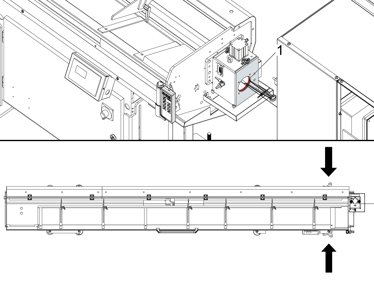
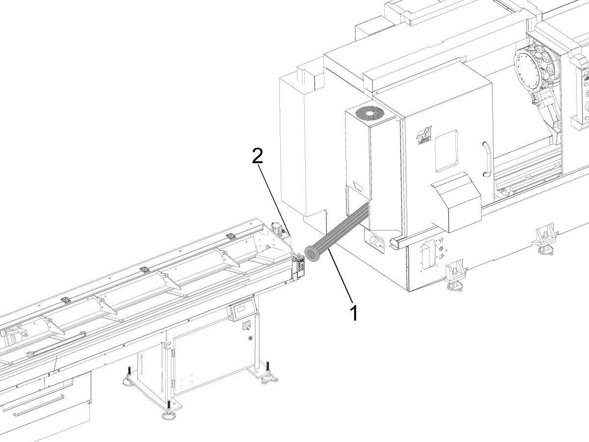
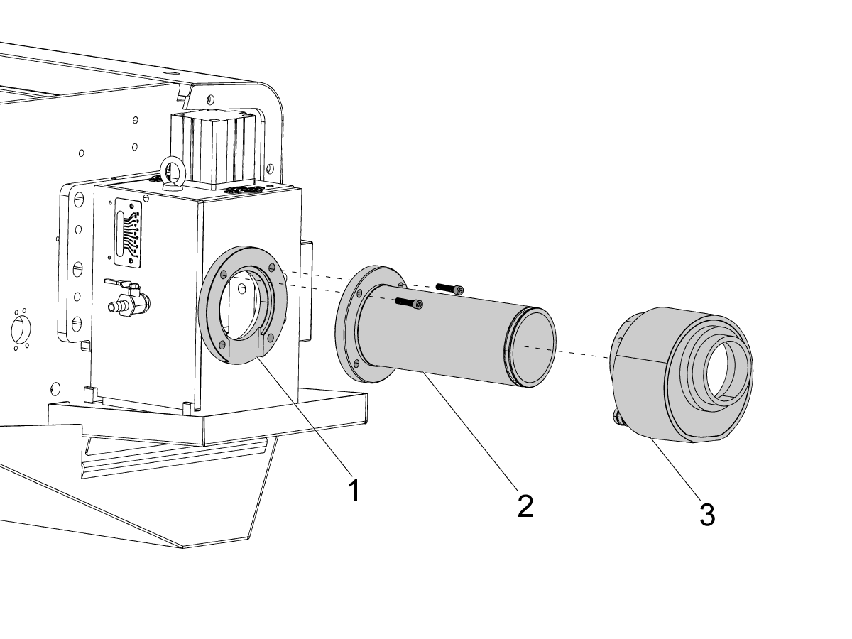
Place the bar feeder between 18 and 20 in (~460 to 510 mm) [1] from the face of the Anti-Vibration Device (AVD) [2] to the back of the spindle on the lathe, leaving room for the extension tube [3].

Loosely install the liner adapter onto the spindle and AVD extension tube onto the bar feeder to verify fitment and correct distance. Actuate the hydraulic union and ensure there is clearance between the machine and bar feeder.

Important : The extension tube is installed at this stage for fitment verification only. Final AVD installation must be completed after the spindle liners have been properly cut and installed. Refer to the Pushrod, Channels, and Liner Installation section later in this procedure for detailed instructions on liner preparation and installation. Do not perform that step at this time.

4

Remove liner adapter on lathe and AVD extension tube from HBF12 to begin alignment process.

Ensure that all 4 metal feet are threaded evenly at 2.0" off the ground. All other height adjustments are done using the bar feeder jacking screws.

5

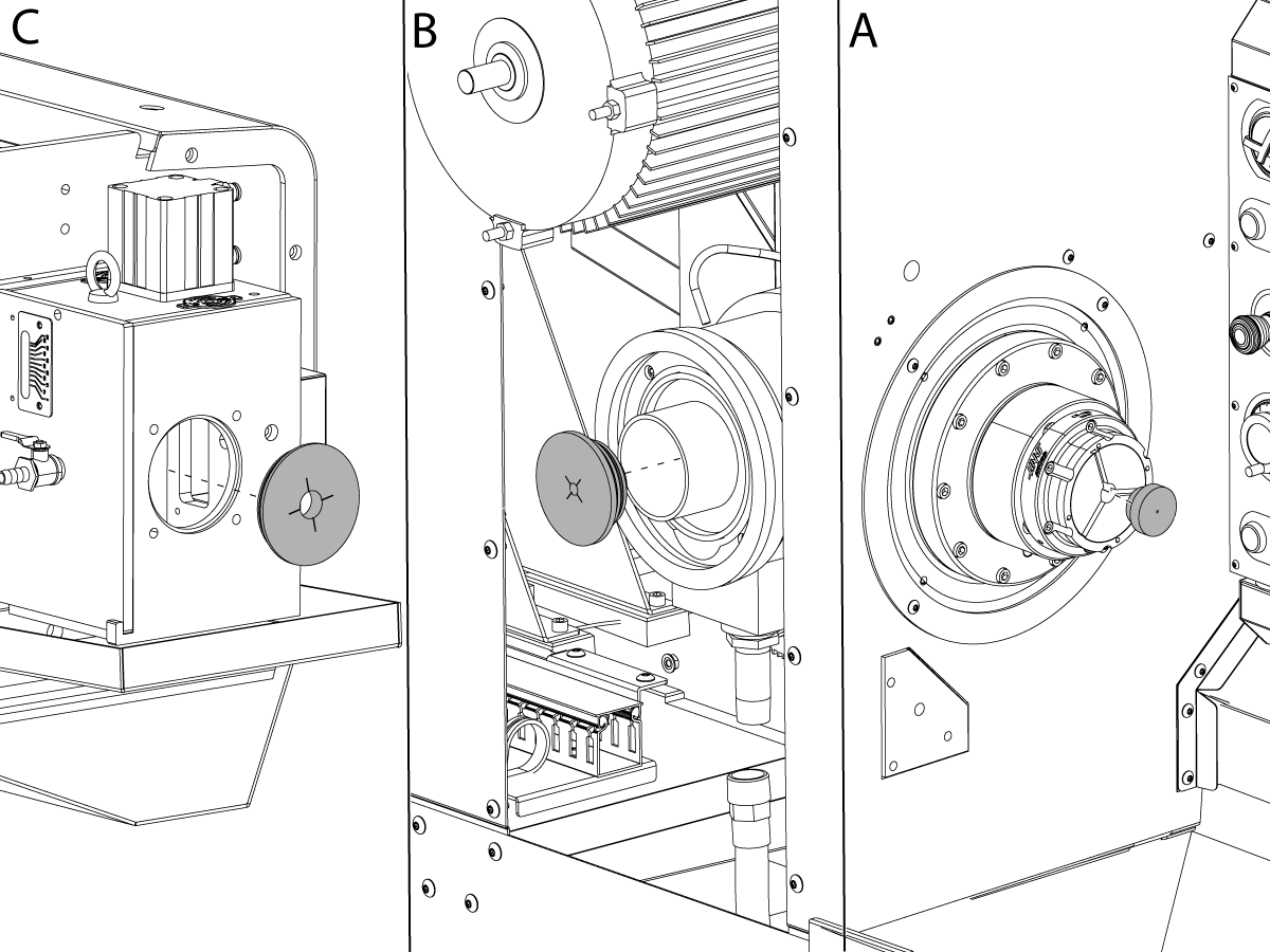
Tie off the nylon string to the smallest alignment puck. Push the puck through the back of the spindle so it comes out the front of the chuck. [2]

Reduce main spindle chuck pressure to 75 PSI and close the jaws so the puck and string sit securely in the chuck.

Thread the string through the back of the spindle and through the AVD.

Pull the string taught through the bar feeder. 

Fasten the end of the nylon string —keeping taut—to the rear bar feeder plate using the pre-drilled tie-off hole. [1]

6

First, align the height of the bar feeder by adjusting the bar feeder jacking screws until string is roughly concentric with the AVD bore. 

Align the front of bar feeder by tapping it with a rubber mallet on the base near the feet and measure the gap difference side to side by visually referencing concentricity of string and AVD bore. [1]

Note: If alignment is off horizontally, the adjust by tapping base with a rubber mallet or pallet jack. If alignment is off vertically, then adjust bar feeder jacking screws. Ensure concentricity of spindle bore, AVD entrance, and string.

Repeat these steps to hone in rough alignment.

7

Align the back of bar feeder by tapping it with a rubber mallet on the base near the feet, measure the gap difference side to side by visually referencing concentricity of spindle bore, and string.

Note: If alignment is off horizontally, the adjust by tapping base with a rubber mallet or pallet jack. If alignment is off vertically, then adjust bar feeder jacking screws. Ensure concentricity of spindle bore, AVD entrance, and string.

Repeat these steps to hone in rough alignment.

8

Now that the bar feeder is roughly aligned, the installation pucks can be used to hone in alignment more accurately. 

Unthread the string through the bar feeder in order to install the last two alignment pucks. 

Expose the closer piston threads by removing the liner adapter and/or the closer rear cover. Insert the puck into the closer bore. [B]

Insert the puck into the AVD bore on the bar feeder. [C]

Make sure the crosshairs etched into the puck sit parallel with the ground. 

Thread the line through both pucks.

9

Pull the string taught through the bar feeder. 

Fasten the end of the nylon string —keeping taut—to the rear bar feeder plate using the pre-drilled tie-off hole. [1]

10

With alignment pucks installed, repeat steps 6 and 7. Ensure the string is concentric with the alignment pucks,  measure the gap difference on all sides by visually referencing the crosshairs etched into the alignment pucks on the back of the spindle and front of the AVD.

Repeat these steps to hone in final alignment.

11

To secure the bar feeder in place after alignment, ensure the bar feeder feet [1] are facing outwards diagonally for ease of drilling and anchoring.

Drill a 2.5 in deep hole into the ground and place the drop in expansion anchors that are supplied with the bar feeder.

Torque to 55 ft-lbs.

Note : Ensure the drilled holes are dust free using a vacuum.

12

Hook up the air supply to the bar feeder using the provided quick connect hose. 

Air regulators settings can be changed to display in bar or PSI using the following steps (verify this):

  1. Hold all buttons to unlock
  2. Press set until unit 
  3. Toggle up/ down until PSI

HBF12 - Electrical Installation

1

Updated

Push [POWER OFF]. Set the main circuit breaker to the [OFF] position.

Warning: After turning off the machine, wait at least 5 minutes before working in the electrical cabinet, to allow power to dissipate. Wait for the voltage indicator LED on the vector drive to go off completely.

Before procedeing with the electrical installation, ensure there is an 8M board installed in the control cabinet.

Please refer to 8M Option - Installation - AD0162


2

Updated

Remove lower conduit retention panel on the lathe. 

If an HBF-12 is ordered for an NGC lathe, the Conduit Retention Panel Retrofit (AD0908) must be completed. Refer to this procedure for installation instructions.

Route cables 33-1568 [HBF E-STOP SIGNAL CBL] and 33-1569 [HBF RELAY ENABLE CBL] through bottom gromet and up into the control cabinet as shown. [1] 

In order to route the cables through you must first:

  • Disconnect 33-1568 [HBF E-STOP SIGNAL CBL] from Safety relay.
  • Disconnect 33-1569  [HBF RELAY ENABLE CBL] from TB1.9 and TB1.10 

3

Reconnect  33-1568 [HBF E-STOP SIGNAL CABLE] to Safety relay.

Reconnect 33-1569 [HBF RELAY ENABLE CBL] to TB1.9 and TB1.10

Connect the safety relay power cable 33-1281 [CABLE 50W 24VDC PS 120VAC POWER IN] to PSUP PCB at P3

4

Install the safety relay next to the low voltage power supply as shown [1]. The relay mounts using a magnetic base.


5

Connect 33-1572 [HBF POWER CABLE] and 33-0787 [CABLE EXTENTION] to the Transformer TB2.

Attach ground connection to chassis or nearest ground cable in surrounding area. 

Reference name on cable to verify correct location. 

6

Connect 33-1567 [HBF SIGNAL CABLE] to IO PCB in P62, P8, P59.

Reference name on cable to verify pin location. 

7

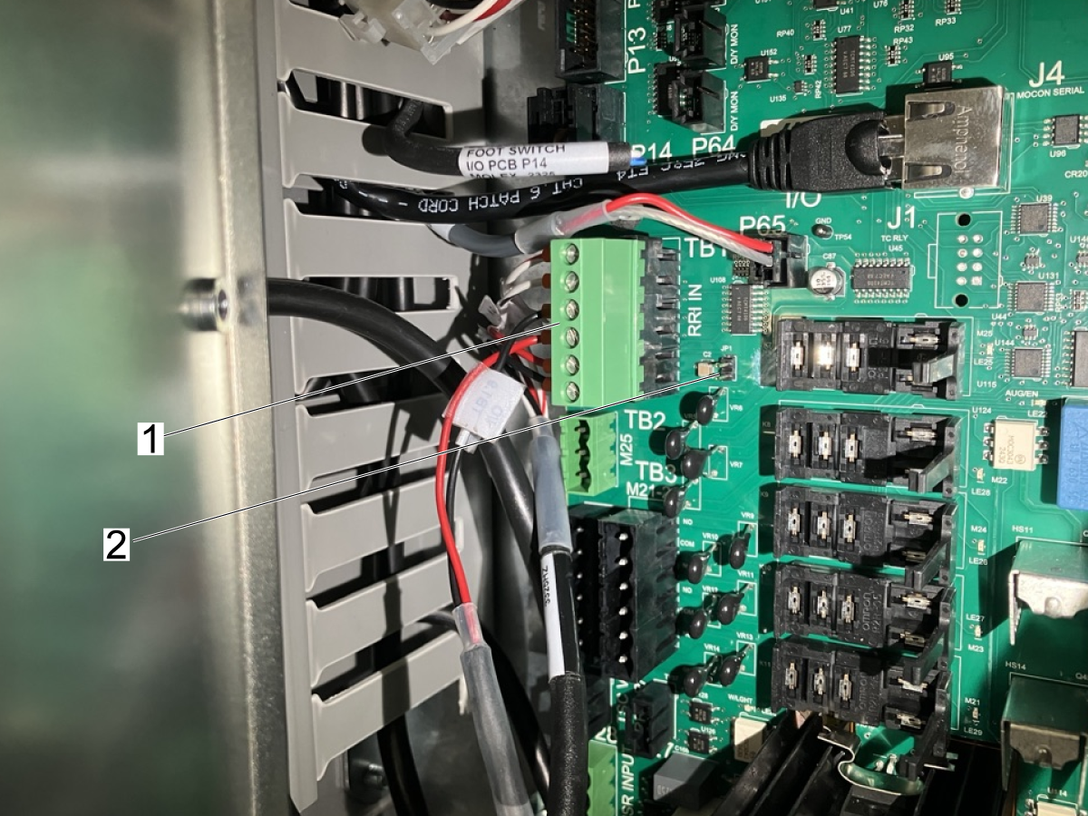
On the I/O PCB:

Connect 33-1569 [HBF RELAY ENABLE CABLE] to TB1-B[1].

Remove jumper JP1 [2].

8

Connect cable 33-1570 [HBF 8M CMD CABLE] to 8M PCB. Ensure the wires are connected to the appropriate ports on M21 / M22 / M23 on the 8M PCB.

Refrence name on cable to verify correct location. 

9

Move the jumper on the 8M PCB from JP1 to JP2. Leave JP5 in its default position; no changes are required.

10

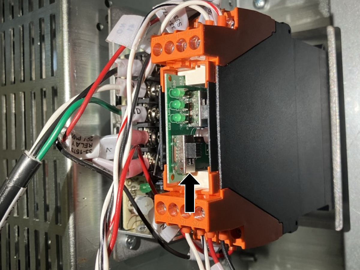
Remove cover on safety relay and set switch to the Automatic and Asymetric position.

11

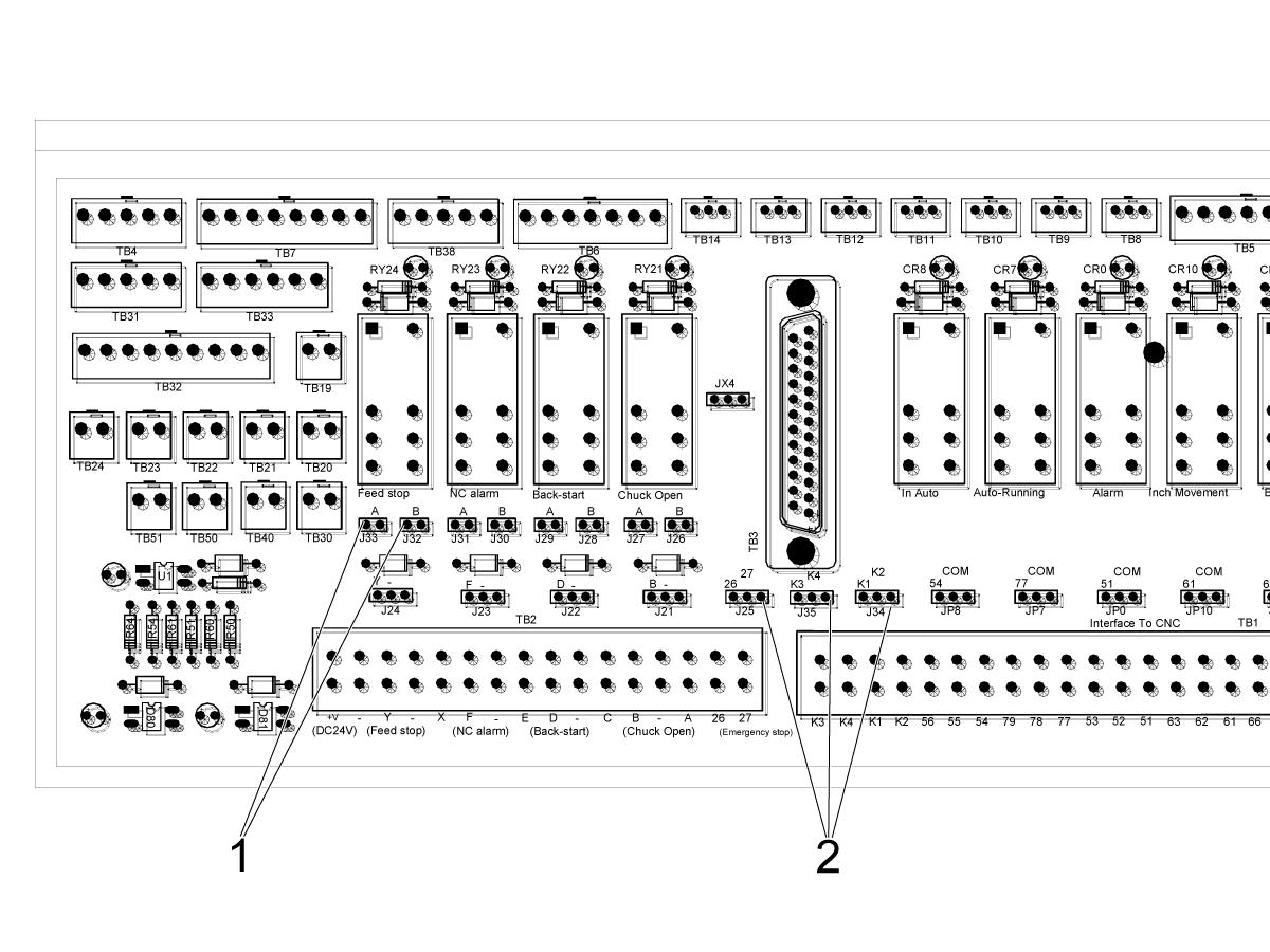
Inside Barfeeder control cabinet:

Change J33 to J32. [1]

Verify J25, J34, and J35 are in the right most position. [2]


Electrical Installation Verification

Updated

Before performing this verification, the HBF-12 must be properly enabled.

  1. Refer to HBF-12 – Enable Code (Section 5.5) to download and load the required G105 macro program into the control. Ensure the Macro option is enabled and the program has been successfully installed before proceeding.
  2.  Install Pushrod / Flag Assembly
    Install the pushrod/flag assembly as shown in the Pushrod, Channels, and Liner Installation section. At this stage, only the trip flag is required. This step is necessary for proper bar feeder operation and must be completed before any system verification or operation. Complete the remaining pushrod, channel, and liner installation steps later in the procedure as instructed.

Lathe → Bar Feeder Signal Verification:

This process verifies that the lathe is correctly sending signals to the bar feeder.

  1. Clamp and unclamp the lathe chuck.
  2. Observe the bar feeder remote handheld device.
  3. Verify:
    • The Chuck Open indicator changes state with chuck clamp/unclamp

NOTE: If the Chuck Open indicator does not change state, verify the 8M relay board installation and configuration. Refer to Step 8 and Step 9.


Bar Feeder → Lathe Signal Verification:

This procedure verifies that the bar feeder is correctly sending signals to the lathe.

  1. On the lathe control, navigate to:
    [DIAGNOSTIC] → I/O Tab
  2. Locate input:
    • Input Software #110 (P59.3)
  3. On the bar feeder remote handheld device:
    • Turn Auto Mode ON and OFF
  4. Verify:
    • Input #110 changes state when Auto Mode is toggled

NOTE: If Input #110 does not change state, verify cable 33-1567 and its connections. Refer to Step 6.

Continue Installation

To complete the remaining installation steps, refer to the Pushrod, Channel, and Liner Installation 4.2 tab.

4.2 Pushrod and Channels Installation

Recently Updated

HBF - 12 Pushrod, Channels, and Liner Installation


Revision B - 04/2026

Pushrod and Channels Installation

1

Updated

Install the left lower guide channels in the orientation as show [1], followed by the proximity sensor pusher[2]. The pusher/trip flag gets installed with two fastensers. This allows the guide channels to open and close, facilitating the second step of the channel installation.

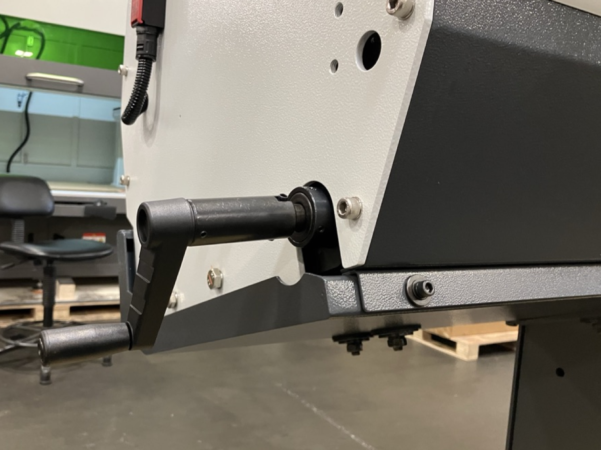
Note: On the outside left face of the bar feeder, there is a manual override knob. Pressing this knob allows the lower channel track to move freely, making it easier to position the guides. This step is not required for installation. Use this method only if you have difficulty positioning the guides

2

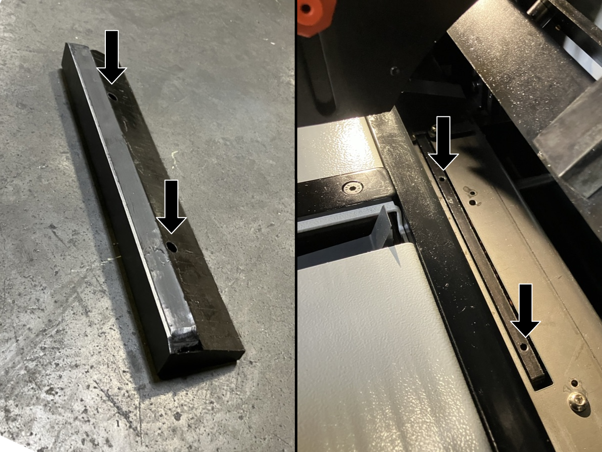
Press the black channel guides into the channel guide brackets as shown in the image. Ensure the holes in the channel guides align with the SHCS heads. Apply firm pressure to the channel guide until it snaps into place.

Repeat this procedure for both the top and bottom channel guide brackets.

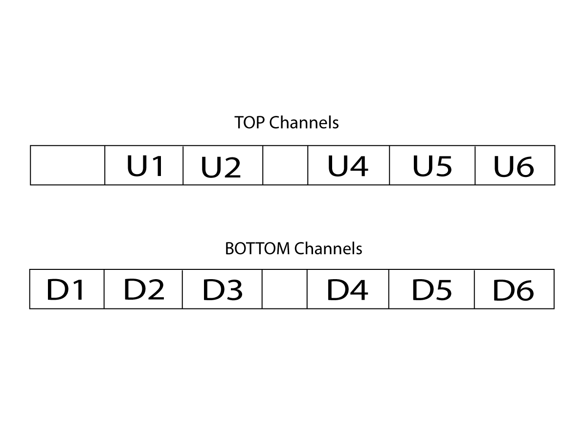
Identify the channel guides by their markings: ‘U’ indicates the upper guides and ‘D’ indicates the 'down' or lower guides.

Note: If the top channel guides do not snap into the top channel guide brackets, use the bar feeder remote to partially close the channel guides. This will provide additional clearance and allow the guides to snap into place more easily.

3

All channel guides have their location engraved on them. Use the provided image to ensure the channel guides are installed in the correct orientation and location.

The channel guide labeled ‘U3’ is not required and should not be installed.

4

Locate the black plate positioned between the lower channel guides at the center of the bar feeder. Remove the two SHCS securing the plate. Position the metal bracket in the same orientation as shown in the image, aligning the mounting holes. Reinstall the previously removed SHCS and tighten to secure the bracket.

5

Assemble and install the pusher bushings. Align the inner bushing [1] inside the outer bushing [2].

Ensure the cutout slots are aligned and facing upward.

Secure the bushings in place using the fastener with the orange handle [3].

6

There are two pusher bushing assemblies. Refer to the image to identify the correct installation locations on the left half of the machine.

7

Feed the front of the bar pusher through the right-most pusher bushing [2].

Feed the rear of the bar pusher through the left-most pusher bushing, aligning the flat plate with the slot in the bushing as shown [1].

Liner Installation

Updated

The spindle liner size and configuration will vary based on the bar feeder kit ordered and the diameter of the material being used.

  1. The liner cannot be installed straight into the spindle. Trim the end of the liner as required to allow it to be inserted at an angle [1].
  2. Remove only enough material to create the necessary clearance from the AVD [2] for installation (typically between 4–10 inches).

Note:

  • The primary function of the spindle liner is to support and guide the material into the spindle, not to fully support the material along the entire spindle length.
  • The amount of material removed will vary depending on the liner size (ID) and machine configuration. Liners with a smaller ID typically require less material removal due to increased flexibility.
  • The exact cut length is not critical, as long as excessive material is not removed. The bar feeder pusher supports the material with a collet at the rear, so when the material extends beyond the liner, it remains supported and will not whip inside the spindle.

Anti-Vibration Device (AVD) Installation

1

Updated

Before completing installation, you must adjust the AVD prior to operation. Refer to HBF-12 – AVD Setup (Section 5.4) for adjustment and operation procedures.

Install The AVD Extension tube assembly. 

Install AVD spacer with cutout facing down as shown[1].

Install AVD extension tub and fasten to spacer with fasteners in top two holes [2].

Install oil collector [3] to AVD extention tube and back of the spindle tube on the Lathe. 

Remnant Catch Tray Installation

Updated

The remnant catch tray is included with the HBF-12 and is used to collect material remnants during operation.

After removing all installation components from the tray, place it inside the enclosure above the HPU/oil reservoir, as shown[1].

The position of the catch tray may be adjusted depending on the material size and where remnants fall during operation.

Note: Periodically remove and empty the catch tray to prevent overflow and ensure proper operation.

4.3 HBF - 12 - Conduit Retention Panel Retrofit

Recently Updated

HBF - 12 Conduit Retention Panel Retrofit


AD0908

Revision A - 10/2025

Introduction

This procedure shows how to retrofit an enclosure cable cover panel onto a Haas ST Lathe.

This Document Applies to the following Service Kits:

  • 93-5581 ENCL CABLE COVER LR KIT ST-10/20/30/40/Y

Machine Compatibility :

  •     ST-10/20/30 and DS-30Y/20Y after 08/2015

 Note : This panel replacement is only necessary if an HBF-12 is ordered for your NGC lathe.

Replacement

1

Remove the older panel (PN 25-12090) and hardware [1] and install the new panel (PN 25-12090A) after sliding the bar feeder conduit in position [2].

2

The new panel has 2 cutouts to both support and lock the cable conduit into position.

  1. Haas Bar feeder V2
  2. HBF-12
Feedback

Recently Viewed Items

You Have No Recently Viewed Items Yet

Feedback
Haas Logo

Haas Delivered Price

This price includes shipping cost, export and import duties, insurance, and any other expenses incurred during shipping to a location in France agreed with you as a buyer. No other mandatory costs can be added to the delivery of a Haas CNC Product.

KEEP UP WITH THE LATEST HAAS TIPS AND TECHNOLOGY...

Sign up now!   

HAAS TOOLING ACCEPTS THE FOLLOWING:

  • Service & Support
  • Owners
  • Request Service
  • Operator Manuals
  • Haas Parts
  • Rotary Repair Request
  • Pre-Install Guides
  • Shopping Tools
  • Build & Price a New Haas
  • Available Inventory
  • The Haas Price List
  • CNCA Financing
  • About Haas
  • Accessibility Statement
  • DNSH Statement
  • Export Compliance
  • Careers
  • Certifications & Safety
  • Contact Us
  • History
  • Terms & Conditions
  • Haas Tooling Terms & Conditions
  • Privacy
  • Warranty
  • Haas Community
  • Haas Certification Program
  • Haas Motorsports
  • Gene Haas Foundation
  • Haas Technical Education Community
  • Events
  • Join the Conversation
  • Facebook
  • X
  • Flickr
  • YouTube
  • LinkedIn
  • Instagram
  • TikTok
© 2026 Haas Automation, Inc – CNC Machine Tools
This site is protected by reCAPTCHA and the Google Privacy Policy and Terms of Service apply.

2800 Sturgis Rd., Oxnard, CA 93030
Toll Free: (888) 817-4446 / Fax: 805-278-8554