My Haas Welcome,
!
Haas Tooling MyHaas/HaasConnect Sign In Register Haas Tooling MyHaas/HaasConnect Sign Out Welcome, My Machines Latest Activity My Quotes My Account My Users Sign Out
Find Your Distributor
  1. Select Language
    1. English
    2. Deutsch
    3. Español - ES
    4. Español - MX
    5. Français
    6. Italiano
    7. Português
    8. Český
    9. Dansk
    10. Nederlands
    11. Magyar
    12. Polski
    13. Svenska
    14. Türkçe
    15. 中文
    16. Suomi
    17. Norsk
    18. الإنجليزية
    19. български
    20. Hrvatski
    21. Ελληνικά
    22. Română
    23. Slovenský
    24. Slovenščina
    25. 한국어
    26. 日本語
    27. Українська
  • machines Main Menu
    • Vertical Mills
      Vertical Mills
      Vertical Mills View All
      • Vertical Mills
      • VF Series
      • Universal Machines
      • VR Series
      • VP-5 Prismatic
      • Pallet-Changing VMCs
      • Mini Mills
      • Mold Machines
      • High-Speed Drill Centers
      • Drill/Tap/ Mill Series
      • Toolroom Mills
      • Pocket Mill
      • Compact Mills
      • Gantry Series
      • SR Sheet Routers
      • Extra-Large VMC
      • Double-Column Mills
      • 3+2 Positioning Machines
    • Multi-Axis Solutions
      Multi-Axis Solutions
      Multi-Axis Solutions View All
      • Multi-Axis Solutions
      • Y-Axis Lathes
      • 5-Axis Mills
    • Lathes
      Lathes
      Lathes View All
      • Lathes
      • ST Series
      • Dual-Spindle
      • Box Way Series
      • Toolroom Lathes
      • Chucker Lathe
      • Pocket Lathe
      • Haas Bar Feeders
    • Horizontal Mills
      Horizontal Mills
      Horizontal Mills View All
      • Horizontal Mills
      • 50-Taper
      • 40-Taper
    • Rotaries & Indexers
      Rotaries & Indexers
      Rotaries & Indexers View All
      • Rotaries & Indexers
      • Rotary Tables
      • Indexers
      • 5-Axis Rotaries
      • Extra-Large Rotaries
    • Special Series
      Special Series
      Special Series View All
      • Special Series
      • EU_Series_Redirect
    • Automation Systems
      Automation Systems
      Automation Systems View All
      • Automation Systems
      • Mill Automation
      • Lathe Automation
      • Automatic Parts Loaders
      • Automation Models
    • Desktop Machines
      Desktop Machines
      Desktop Machines View All
      • Desktop Machines
      • Desktop Mill
      • Desktop Lathe
      • Control Simulator, Standard
      • Control Simulator, Premium
    • Shop Equipment
      Shop Equipment
      Shop Equipment View All
      • Shop Equipment
      • Knee Mill
      • Haas Manual Lathes
      • Haas Saws
    • Fabrication Machines
      Fabrication Machines
      Fabrication Machines View All
      • Fabrication Machines
      • Laser Cutting Machines
      • CNC Press Brakes
    • QUICK LINKS Special Series  Special Series 
      EU SERIES EU SERIES BUILD & PRICE | PRICE LIST BUILD & PRICE | PRICE LIST In-Stock Machines In-Stock Machines WHAT’S NEW WHAT’S NEW YOUR FIRST CNC YOUR FIRST CNC
      SHOPPING TOOLS
      • Build & Price a Haas
      • Price List
      • Available Inventory
      • CNCA Financing
      WANT TO TALK TO SOMEONE?

      A Haas Factory Outlet (HFO) can answer your questions, and walk you through your best options.

      CONTACT YOUR DISTRIBUTOR >
  • Options Main Menu
    • The Haas Control Value Option Packages
      Value Option Packages
      Value Option Packages View All
      • Value Option Packages
    • Product Image Spindles
      Spindles
      Spindles View All
      • Spindles
    • Product Image Tool Changers
      Tool Changers
      Tool Changers View All
      • Tool Changers
    • Product Image 4th- | 5th-Axis
      4th- | 5th-Axis
      4th- | 5th-Axis View All
      • 4th- | 5th-Axis
    • Product Image Turrets & Live Tooling
      Turrets & Live Tooling
      Turrets & Live Tooling View All
      • Turrets & Live Tooling
    • Product Image Probing
      Probing
      Probing View All
      • Probing
    • Haas Chip & Coolant Management Chip & Coolant Management
      Chip & Coolant Management
      Chip & Coolant Management View All
      • Chip & Coolant Management
    • The Haas Control The Haas Control
      The Haas Control
      The Haas Control View All
      • The Haas Control
    • Product Image Product Options
      Product Options
      Product Options View All
      • Product Options
    • Product Image Tooling & Fixturing
      Tooling & Fixturing
      Tooling & Fixturing View All
      • Tooling & Fixturing
    • Product Image Workholding
      Workholding
      Workholding View All
      • Workholding
    • Product Image 5-Axis Solutions
      5-Axis Solutions
      5-Axis Solutions View All
      • 5-Axis Solutions
      • 5 Easy Steps to 5-Axis
    • QUICK LINKS Special Series  Special Series 
      EU SERIES EU SERIES BUILD & PRICE | PRICE LIST BUILD & PRICE | PRICE LIST In-Stock Machines In-Stock Machines WHAT’S NEW WHAT’S NEW YOUR FIRST CNC YOUR FIRST CNC
      SHOPPING TOOLS
      • Build & Price a Haas
      • Price List
      • Available Inventory
      • CNCA Financing
      WANT TO TALK TO SOMEONE?

      A Haas Factory Outlet (HFO) can answer your questions, and walk you through your best options.

      CONTACT YOUR DISTRIBUTOR >
  • Why Haas Main Menu
      Discover the Haas Difference
    • Why Haas
    • MyHaas
    • Education Community
    • Industry 4.0
    • Haas Certification
    • Customer Testimonials
  • Service Main Menu
      Welcome to Haas Service
      SERVICE HOME Operator’s Manuals How-To Procedures Troubleshooting Guides Preventive Maintenance Haas Parts Haas Tooling Videos
  • Videos Main Menu
  • Main Menu
    • View All
    • View All
    • View All
    • View All
      • HTEC Curriculum Support
      • Haas Value Option Packages (VOP) Journey
    • View All
      • Haas 10 kg Cobot Package
      • Cobot Kits
      • DC-1 Drill Center
      • CNC Sales News
      • Do More With Your Haas
    • View All
    • View All
      • contact-us-test
      • 4 - AUTOMATION SYSTEMS
      • Carousel-V2
      • expert test
      • Demo_Day_Trident-test
      • Link Test
      • image-sale-tag-test
      • article-list-test
      • Haas 25 kg Robot Package
      • test-algolia-page
    • View All
    • View All
    • View All
    • View All
      • calc-test
    • View All
    • QUICK LINKS Special Series  Special Series 
      EU SERIES EU SERIES BUILD & PRICE | PRICE LIST BUILD & PRICE | PRICE LIST In-Stock Machines In-Stock Machines WHAT’S NEW WHAT’S NEW YOUR FIRST CNC YOUR FIRST CNC
      SHOPPING TOOLS
      • Build & Price a Haas
      • Price List
      • Available Inventory
      • CNCA Financing
      WANT TO TALK TO SOMEONE?

      A Haas Factory Outlet (HFO) can answer your questions, and walk you through your best options.

      CONTACT YOUR DISTRIBUTOR >
  • Haas Tooling Main Menu
  • Haas Service Parts Main Menu

My Haas Welcome,
!
Haas Tooling MyHaas/HaasConnect Sign In Register Haas Tooling MyHaas/HaasConnect Sign Out Welcome, My Machines Latest Activity My Quotes My Account My Users Sign Out
Find Your Distributor
  1. Select Language
    1. English
    2. Deutsch
    3. Español - ES
    4. Español - MX
    5. Français
    6. Italiano
    7. Português
    8. Český
    9. Dansk
    10. Nederlands
    11. Magyar
    12. Polski
    13. Svenska
    14. Türkçe
    15. 中文
    16. Suomi
    17. Norsk
    18. الإنجليزية
    19. български
    20. Hrvatski
    21. Ελληνικά
    22. Română
    23. Slovenský
    24. Slovenščina
    25. 한국어
    26. 日本語
    27. Українська
×

Search Results

Web Pages

Images

    • <
    • 1
    • >

GR Mill - Installation - AD0092

Service Home How To Procedures GR Mill - Installation - AD0092

GR Mill - Installation - AD0092

- Jump to Section - Back to Top
Recently Updated Last updated: 11/08/2023

GR Mill - Installation


AD0092

Introduction

1

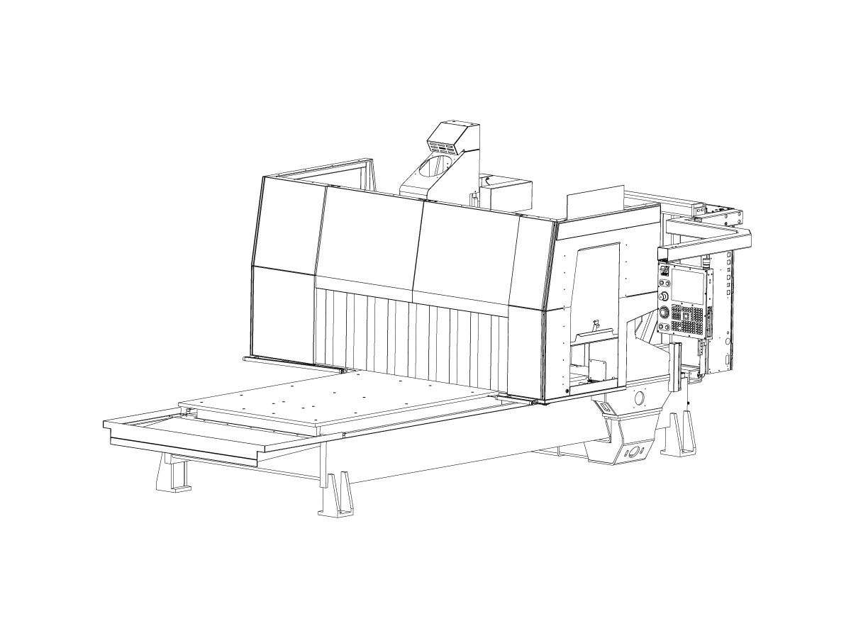
This installation procedure for the GR Mill tells you how to:

  1. Move the GR Mill into position for setup.
  2. Remove the spindle-head shipment screws.
  3. Remove the shipping brackets.
  4. Reposition the pendant arm.
  5. Reposition the 20-pocket tool changer.
  6. Align 20-pocket tool changer.
  7. Install the chip and coolant splash shield.
  8. Install the electric safety sensors.

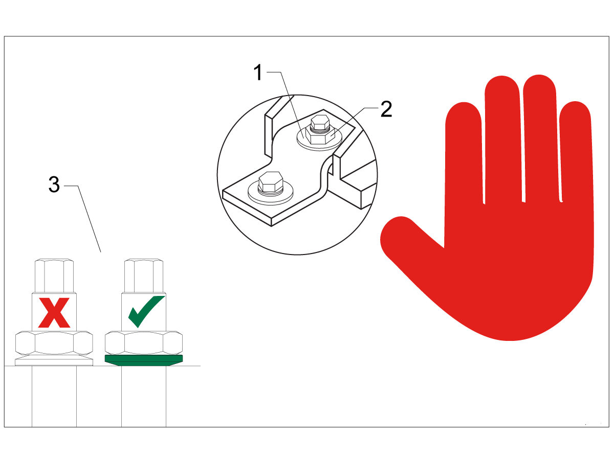
Leveling Screws Hardware

Note: The washers [1] and nuts [2] are installed during shipping and should be saved for installation and not be discarded.

Note: The washer orientation [3] is important.  The conical part of the washer should be against the casting,  see illustration.

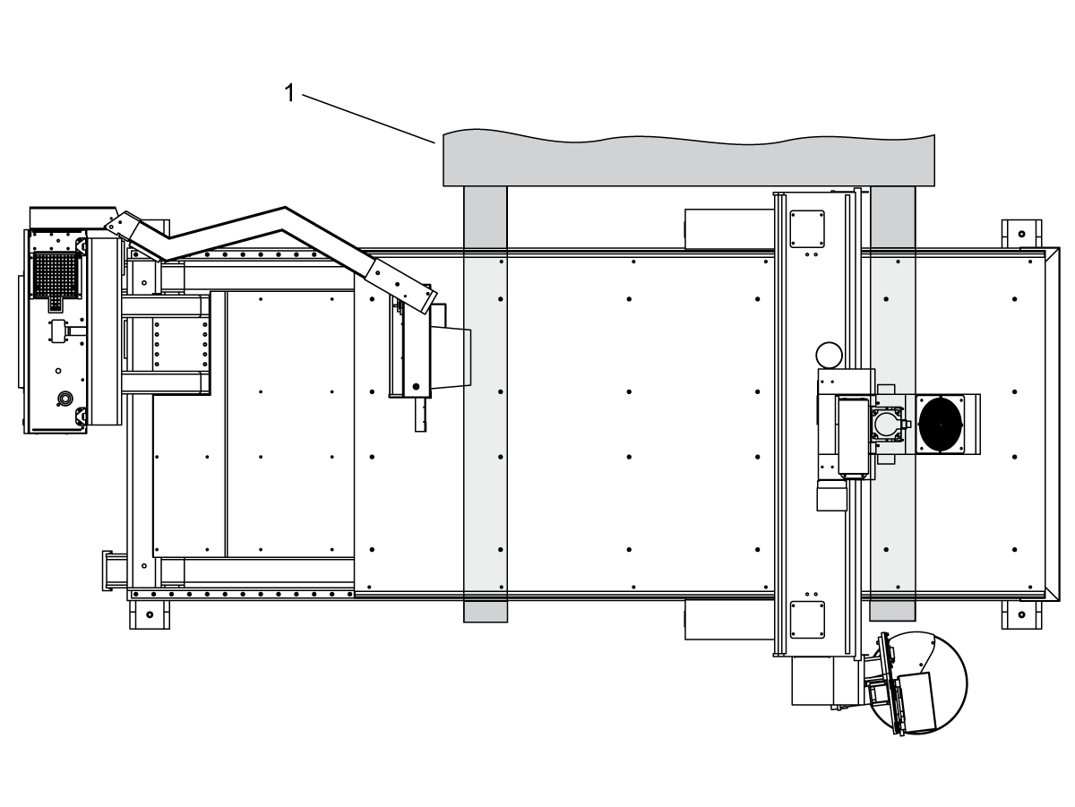
Move the GR Mill into position for setup.

Use a forklift that can lift a minimum of 18,000 lb (8165 kg). The illustration shows an estimate of the correct forklift [1] position.

Removal of Rust Inhibitor

Electrical Connections

 DANGER: Working with the electrical services required for CNC machines is extremely hazardous and can result in serious injury or death.

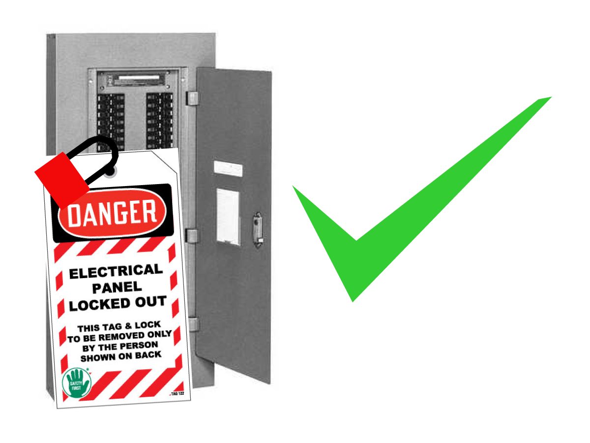
Before connecting line wires to the CNC:

  • Turn off all power to the machine at the source.
  • Perform a Lockout-Tagout (LOTO) procedure to ensure the power remains off during service.
  • Verify that power has been disconnected by using an AC voltage detector on all incoming lines.

If you are uncertain about how to safely disconnect power or perform LOTO procedures:

  • Do not proceed.
  • Contact qualified personnel or obtain appropriate assistance before continuing.

Failure to follow these precautions may result in electrical shock, equipment damage, or fatal injury.

1

Initial Control Inspection

Danger: At this point, there should be no electrical connection to the machine. Electrical panel must be closed and secured. When main switch is on, there is HIGH VOLTAGE throughout the electrical panel (including the circuit boards and logic circuits) and some components operate at high temperatures. Therefore, exercise extreme caution when working in the panel.

  • Set the main breaker switch at the upper right of the electrical panel on the back of the machine to OFF.
  • Using a screwdriver, unlock the two latches on the panel door, unlock the cabinet with the key and open the door.
  • Take sufficient time to check all the components and connectors associated with the circuit boards. Look for any cables that have become disconnected, look for any signs damage and loose parts in the bottom of the panel box. If there are any signs that the machine was mishandled, call the factory before proceeding.

2

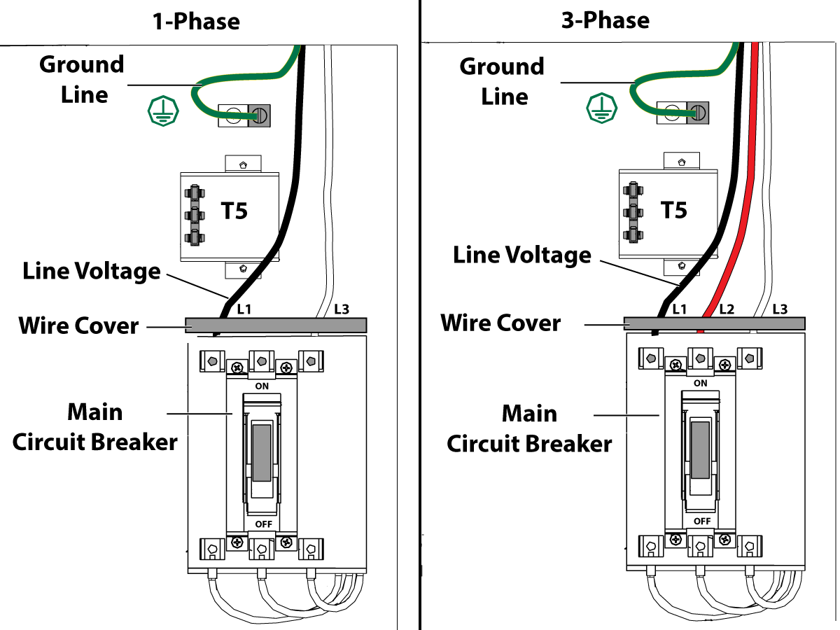
1-Phase Machines: Insert each power lead into the wire cover.  Connect the two power leads to L1 and L3 terminals on top of the main circuit breaker.

3-Phase Machines: Insert each power lead into the wire cover.  Connect the three power leads to L1, L2 and L3 terminals on top of the main circuit breaker.

Connect the separate ground line to the ground bus to the left of the terminals.

For 3-phase machines, check to see what type of power configuration is supplying the machine. Take voltage measurements of each power lead to ground line. Then refer to RD0084 - Input Power Configurations to determine which power lead should be connected to the L1 terminal based of the voltage readings and power configuration.

Refer to Haas Main Circuit Breaker - Torque Specifications for what value to torque the circuit breaker power leads.

 Note: Make sure that the leads actually go into the terminal-block clamps . (A poor connection will cause the machine to run intermittently or have other problems, such as servo overloads.) To check, simply pull on the wires after the screws are tightened.

3

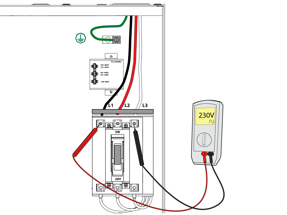
After the line voltage is connected to the machine, make sure that main circuit breaker (at top-right of rear cabinet) is OFF . Remove the Lockout / Tagout and Turn ON the power at the source. Using a digital voltmeter and appropriate safety procedures: 

1-Phase Machines: Measure the AC voltage across L1 & L3 at the main circuit breaker.  The AC voltage must be between 220 - 250 volts .
Note: Lower or higher than this voltage can generate low/high voltage alarms.

3-Phase Machines : Measure the AC voltage between all three pair phases at the main circuit breaker. 

The AC voltage must be between 195 and 260 volts (360 and 480 volts for high voltage option).

SMinimill - Reboot: The AC voltage must be between 198 and 242 volts for machines without a high voltage transformer.  Refer to the Minimill/SMinimill - Identification document.

 Note: Wide voltage fluctuations are common in many industrial areas; minimum and maximum voltage supplied to a machine while it is in operation must be known. U.S. National Electrical Code specifies that machines should operate with a variation of +5% to -5% around an average supply voltage. If problems with line voltage occur, or low line voltage is suspected, an external transformer may be used. If you suspect voltage problems, voltage should be checked every hour or two during a typical day to be sure it does not fluctuate more than +5% or -5% from an average.

4

Important: With the main circuit breaker turned OFF.

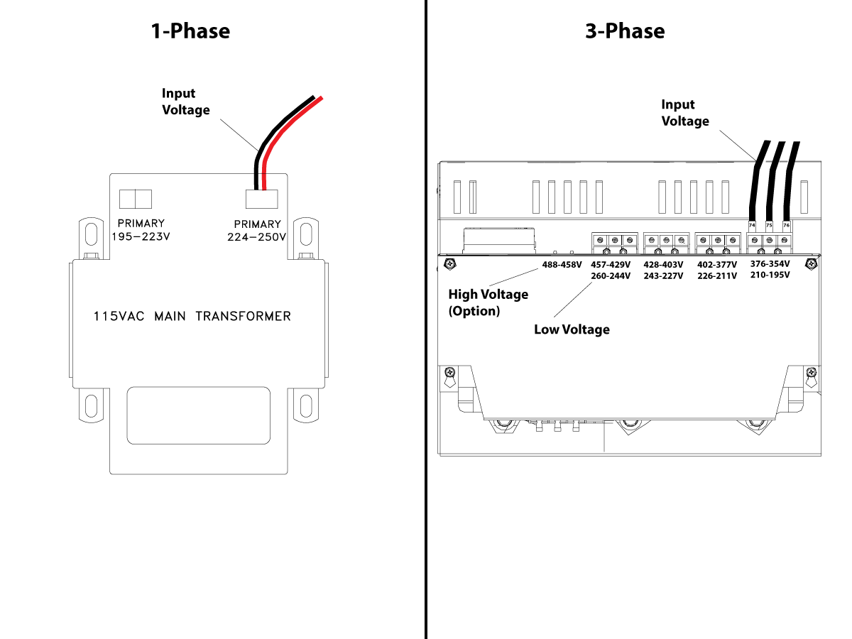
Check the transformer taps at the bottom-right corner of the rear cabinet.

1-Phase Machines: The input voltage cable must be moved to the connector which corresponds to the average voltage measured in the above step.

3-Phase Machines:  The input voltage cables labeled 74, 75, and 76 must be moved to the terminal block triple which corresponds to the average voltage measured in the above step.

5

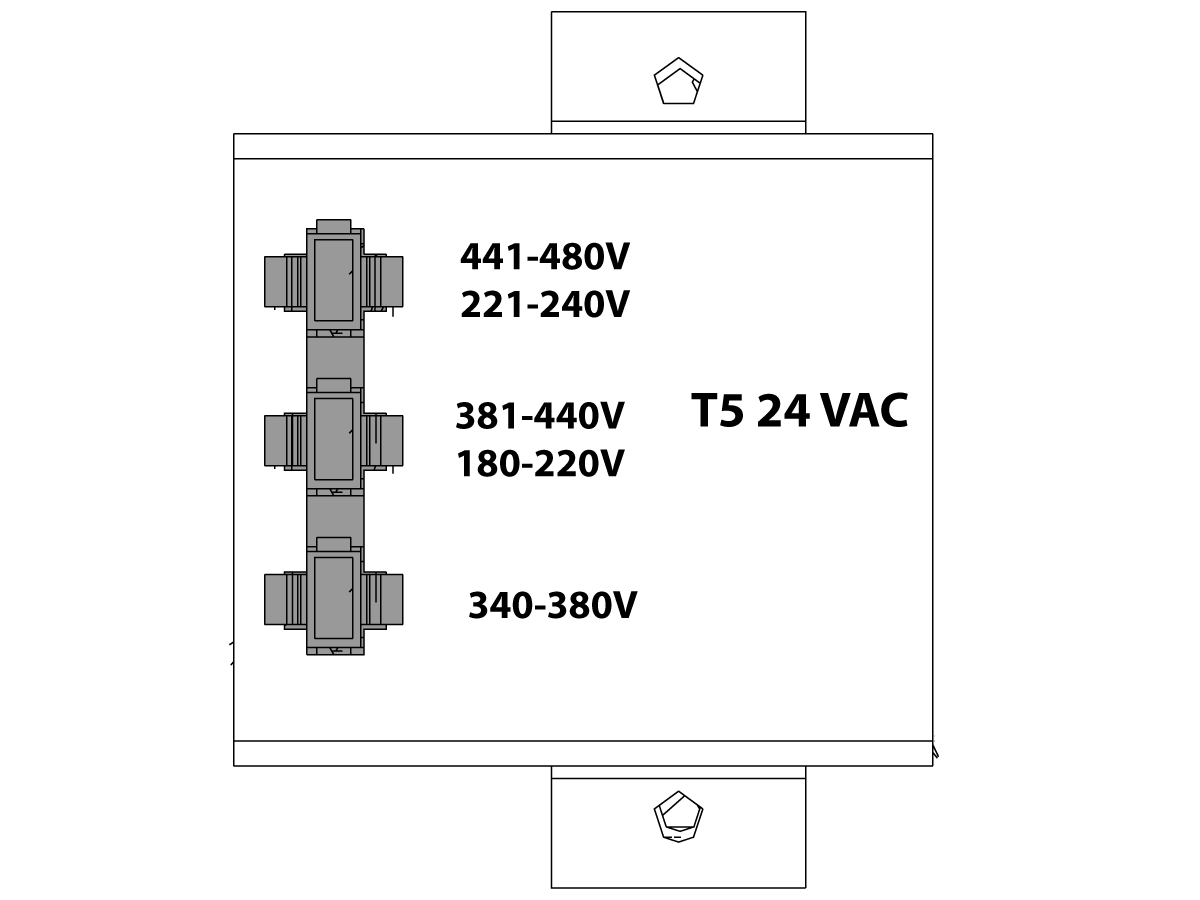
Transformer T5 supplies 24VAC used to power the main contactor. There are two versions of this transformer for use on a 240 and 400V machines. The 240V transformer has two input connectors located about two inches from the transformer, which allow it to be connected to either 180-220V or 221-240V.

Users that have 220V-240V RMS input power should use the connector labeled 221-240V, while users with 190-220V input power should use the connector labeled 180-220V. Failure to use the correct input connector will result in either overheating of the main contactor or failure to reliably engage the main contactor.

The 480V (option) T5 transformer has three input connectors, labeled 340-380V, 381-440V and 441-480V.

Users with 340-380V 50/60Hz power should use the 340-380V connector while users with 380V-440V 50/60Hz power should use the 381-440V connector.

Important: Set the main circuit breaker to ON. Check for evidence of problems, such as the smell of overheating components or smoke. If such problems are indicated, immediately set the main circuit breaker to OFF and call the factory before proceeding.

After the power is on, measure the voltage across the bottom terminals on the main circuit breaker. It should be the same as the measurements where the input power connects to the main breaker. If there are any problems, check the wiring.

6

Apply power to the control by pressing the Power-On switch on the front panel.

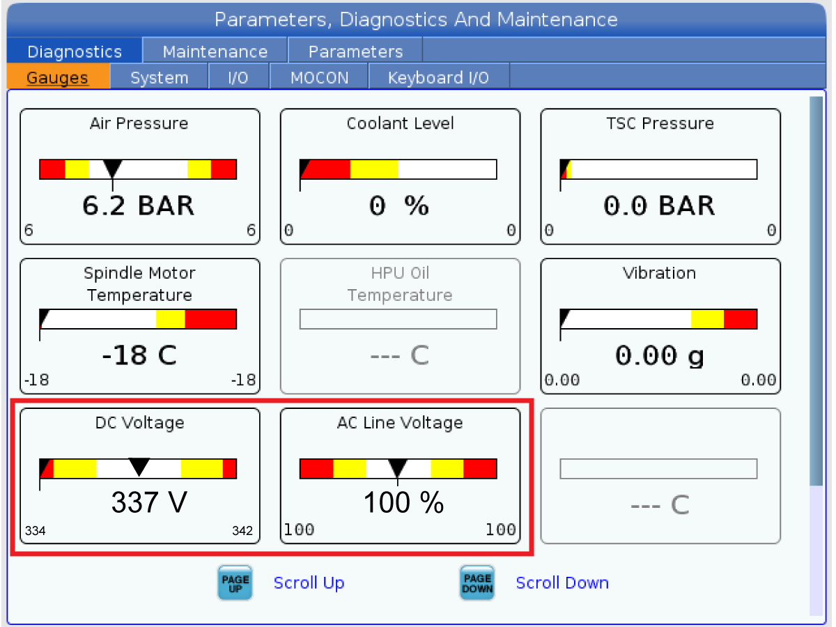
Check the DC Voltage and AC Line Voltage gauges in Diagnostics. The DC Voltage gauge must read between 310 - 360V. The AC Line Voltage must be between 90 and 105 percent. If the voltage is outside these limits, turn off the power and recheck steps 2 and 3. If the voltage is still outside these limits, call the factory.

7

Electrical power must be phased properly to avoid damage to your equipment. The Power Supply Assembly PC board incorporates a "Phase Detect" circuit with neon indicators. When the orange neon is lit (NE5), the phasing is incorrect. If the green neon is lit (NE6), the phasing is correct. If both neon indicators are lit, you have a loose wire; check the connections. Adjust phasing by setting the source power to off and then swapping L1 and L2 of the incoming power lines at the main circuit breaker.

Danger: ALL POWER TO CNC MUST BE TURNED OFF LOCKOUT-TAGOUT AT THE SOURCE PRIOR TO ADJUSTING PHASING. ALWAYS DOUBLE CHECK THE INCOMING LINES WITH AN AC VOLTAGE DETECTOR.

Turn off the power and set the main circuit breaker to OFF. Close the door, lock the latches, and turn the power back on.

Remove the key from the control cabinet and give it to the shop manager.

8

Activation

When the machine is properly placed and connected to both air and electrical power, it is ready for final installation (removing shipping blocks, leveling, spindle sweep, etc.) and software activation. The HFO service technician does this. Contact the local HFO to schedule the work.

IMPORTANT:  Machines equipped with motion sensors must be rough‑leveled before attempting to arm the motion sensor.  For detailed instructions, refer to Service Notification - SA0007.  Access to this document is restricted to Haas Factory Outlet personnel.

Shipping Brackets - Removal

1

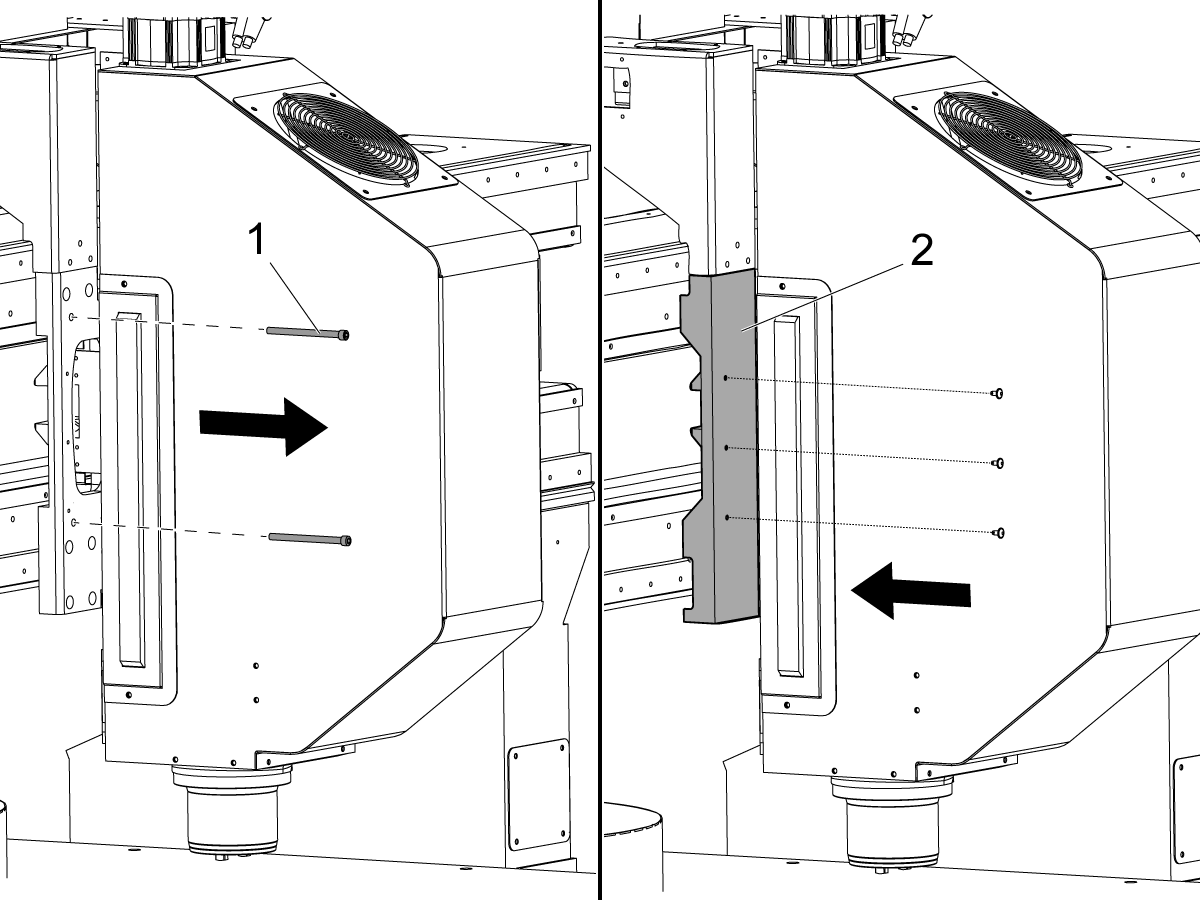
  • Remove the (2) screws [1] that prevent Y-Axis movement.
  • Attach the cover [2] with the (3) screws.

2

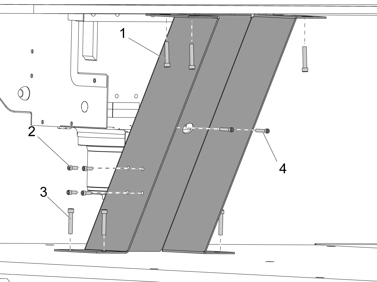
  • Remove the (4) screws [1] that attach the shipping bracket to the bridge.
  • Remove the (4) shorter screws [2] from the side of the shipping bracket. Keep these screws.
  • Remove the (4) longer screws [3] that attach the shipping bracket to the table. Keep the screws.
  • From the rear of the shipping bracket, remove the (2) screws [4] that attach the shipping bracket to the spindle.
  • Remove the shipping bracket.
 

Note: Keep the screws with the shipping bracket. If you must move the machine to a different location, you can install the bracket.

Note: If the machine has the optional Extended Z-Axis Clearance 6" (152 mm) or 24" (610 mm) riser option, the bracket separates into (2) pieces.

  • Install the (4) shorter screws [2] that you removed from the side of the shipping bracket into the table.
  • Torque the screws. Refer to Haas Fastener Torque Specifications. Use the value for aluminum.

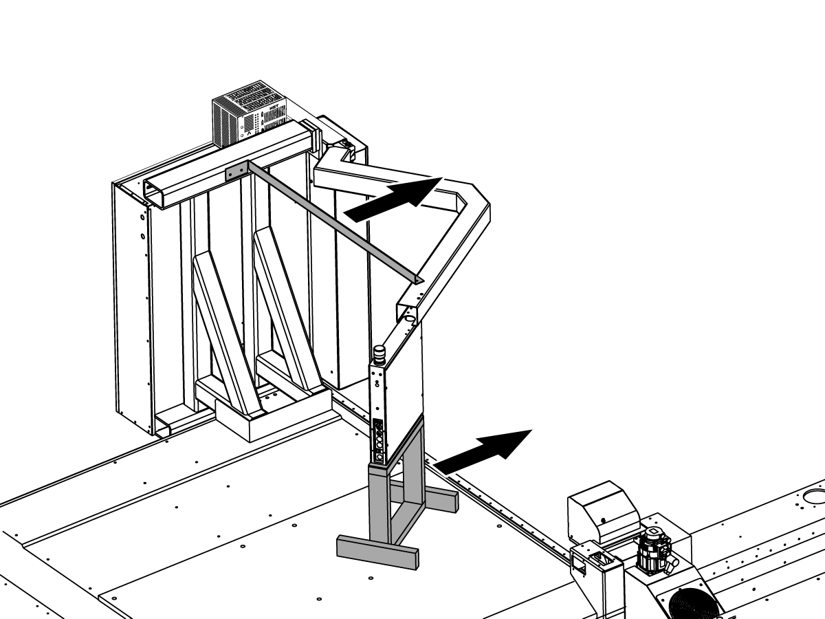
3

  • Remove the pendant shipping brackets.

4

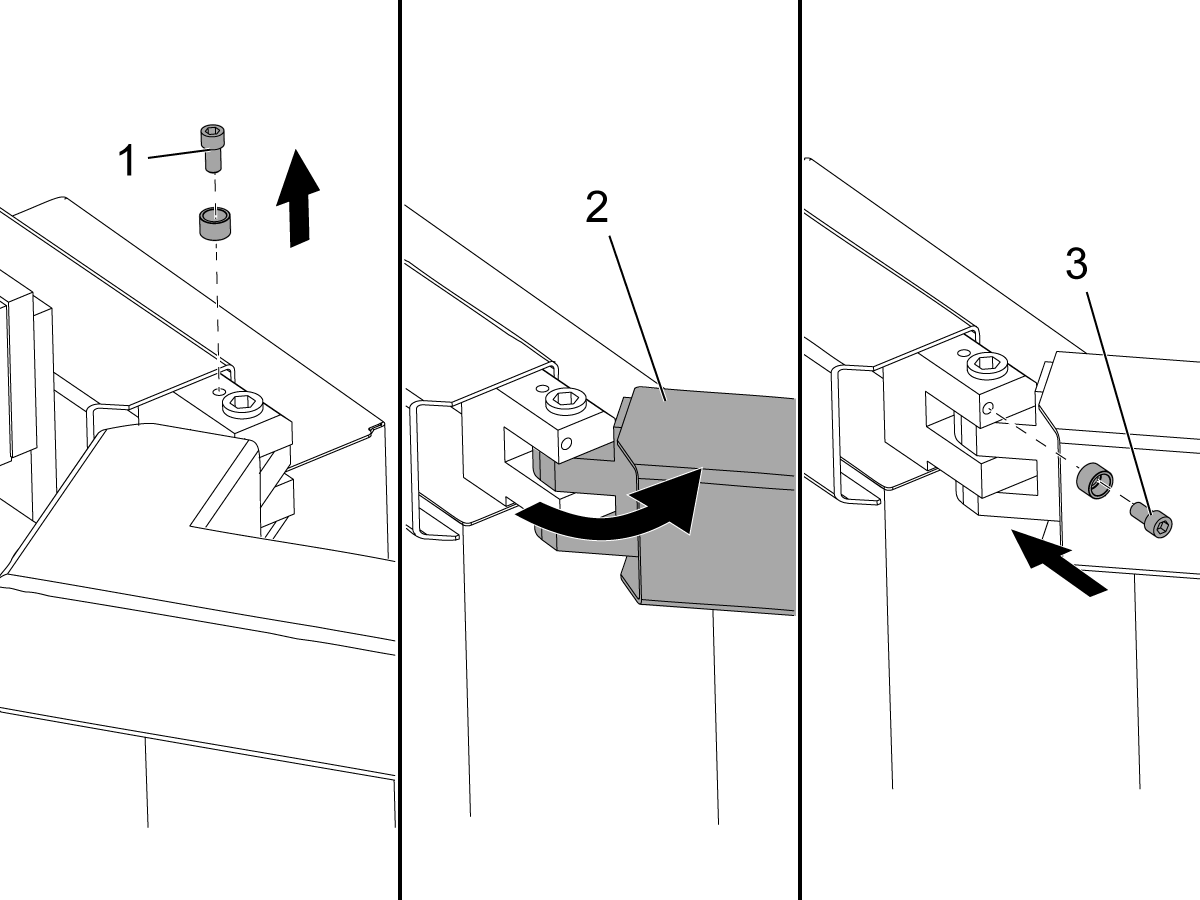
  • Remove the screw [1] and the spacer from the top of the arm joint. Keep the screw and the spacer.
  • Turn the arm [2] to the operation position.
  • Insert the screw [3] and the spacer into front of the joint. Torque the screws. Refer to Haas Fastener Torque Specifications. Use the value for steel.
  • Pull the boot over the joint and tighten the clamps.

20-Pocket Tool Changer - Alignment

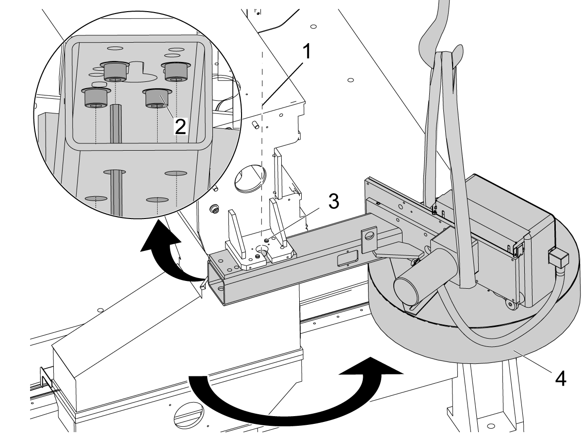
1

Note: This step applies to 20 pocket TC only.
 
  • Support tool changer with hoist.
  • Remove 4 SHCS attaching the TC arm.
  • Turn tool changer around 180 degrees.
  • Install 4 SHCS to reattach TC arm.

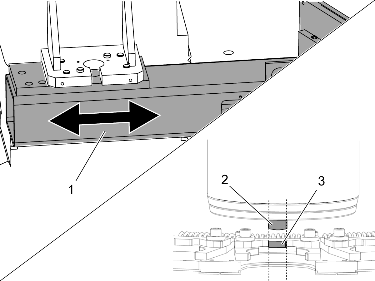
2

  • Adjust the tool changer assembly where it mates with the machine [1], so that the spindle dog [2] aligns with the tool alignment key [3].].

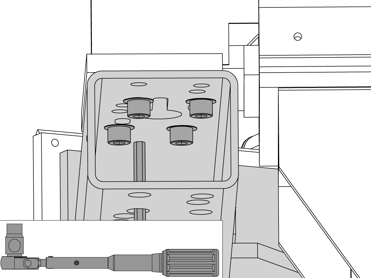
3

  • Tighten and then torque the (4) screws that hold the tool changer to the machine. Refer to Haas Fastener Torque Specifications. Use the value for steel.


  • Make sure Parameters 257 and Parameter 64 are correct. 
  • Do these procedures:

Umbrella Tool Changer - Spindle Orientation Offset - Parameter 257

Umbrella Tool Changer - Set Parameter 64 - Z Axis Tool Change Offset

Chip and Coolant Splash Shield - Installation

1

  • Apply Sikaflex construction sealant (or equivalent) where you will attach the drip tray. Apply the Sikaflex along the full distance. This prevents coolant leakage.

2

  • Attach the front drip tray. Use the (9) 3/8-16x1/2 socket head cap screws (SHCS) and (9) washers. Torque the screws. Refer to Haas Fastener Torque Specifications. Use the value for steel.
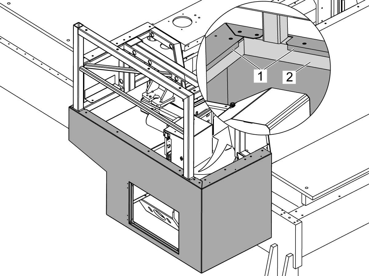
  • Apply Sikaflex construction sealant (or equivalent) to the space on each side [1] of the drip tray.

3

  • This illustration shows where to apply Sikaflex construction sealant (or equivalent) to the spaces from the rear view.

4

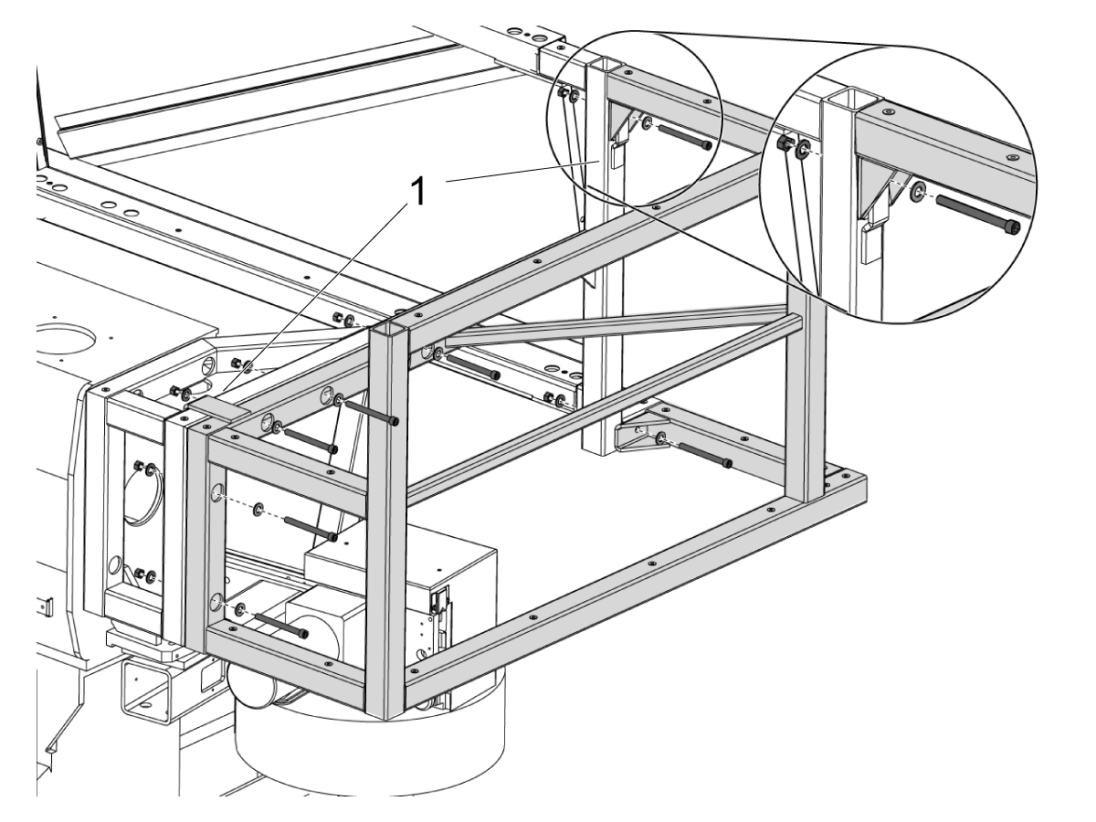
  • Find the (2) hooks [1].
  • Hang the outer frame piece onto hooks on the inner frame piece. Use a lifting device.
  • In the subsequent steps, keep all of the screws loose until you assemble all the frame parts. Then tighten them.
  • Attach the outer frame piece onto the inner frame piece. Use the (7) 3/8-16 x 1" socket head cap screws (SHCS). Use (1) nut and (2) washers for each screw, as shown.

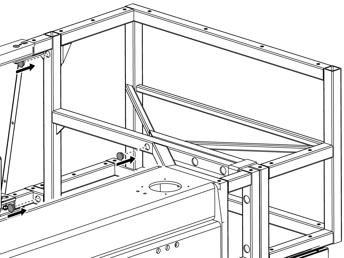
5

  • Put the (3) plastic covers into the holes that point into the machine.

6

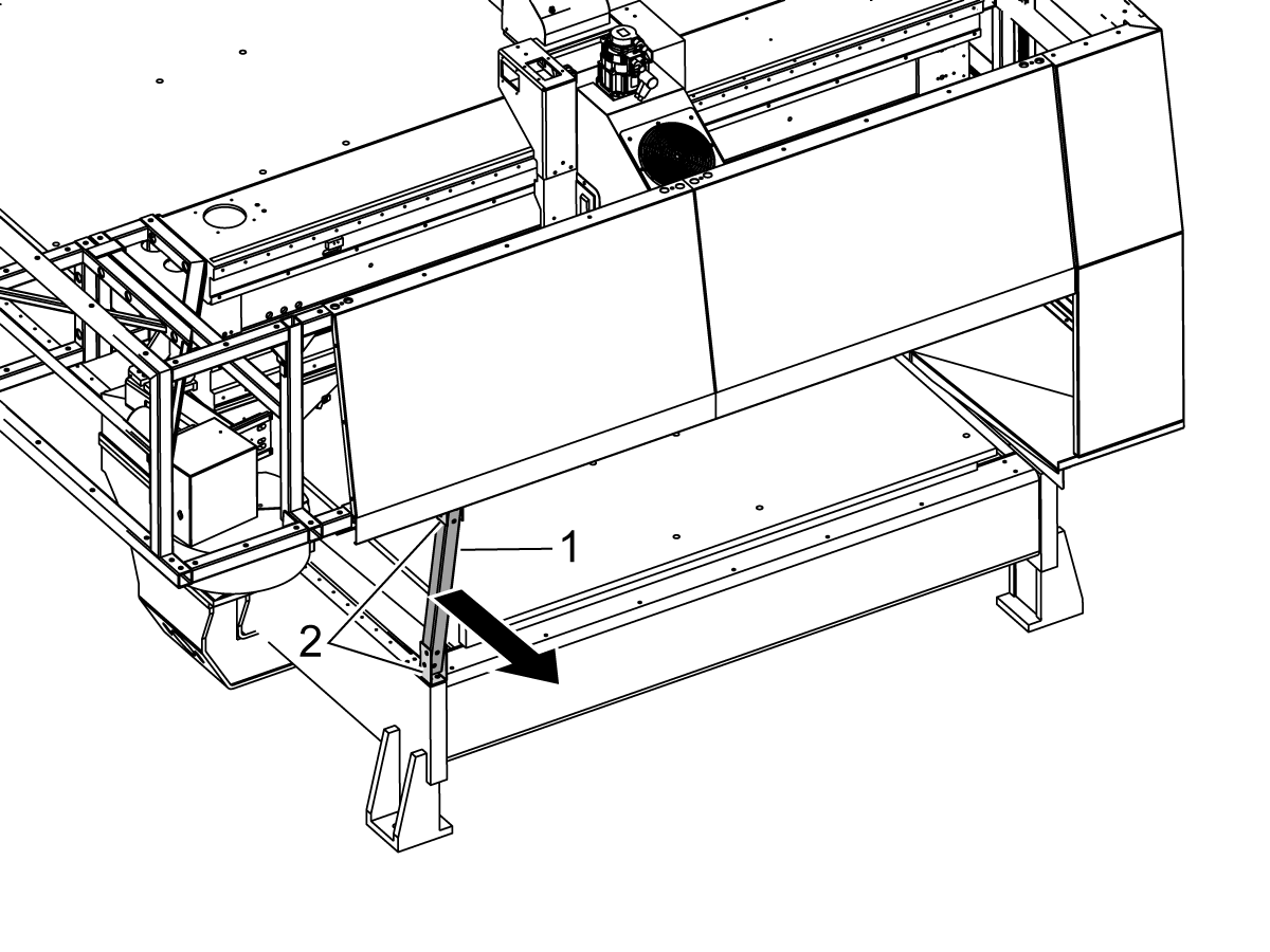
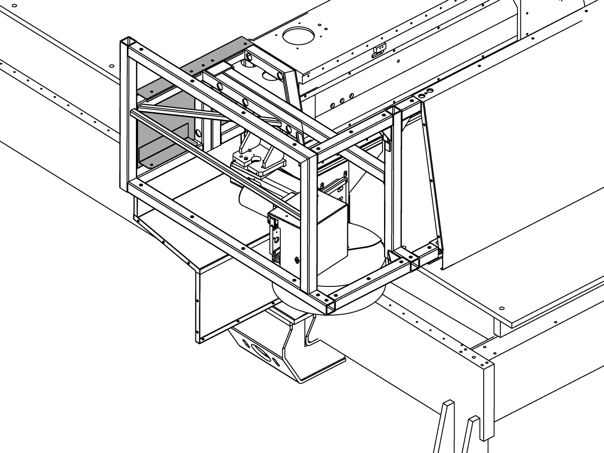
  • Remove the frame shipping brackets. There is (1) middle piece [1] and (2) end pieces [2].

7

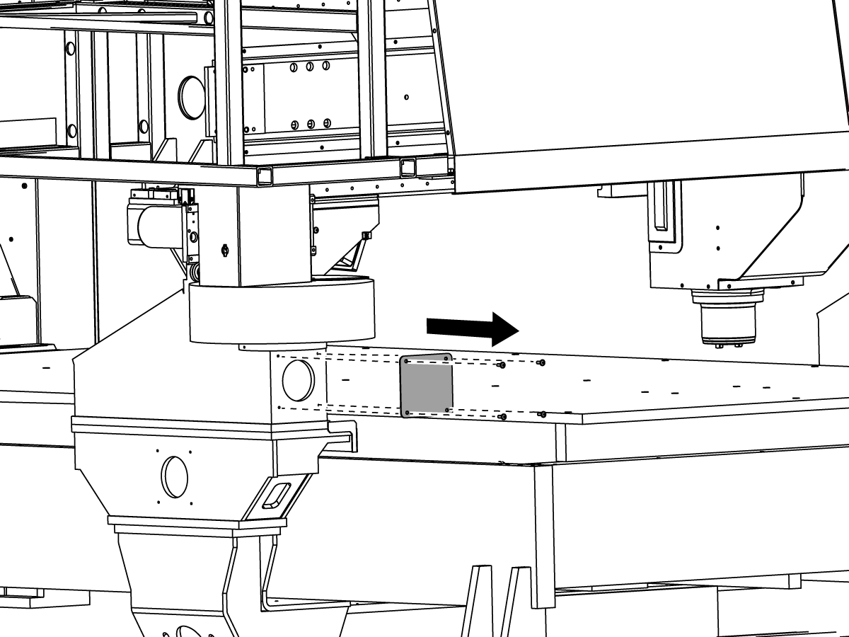
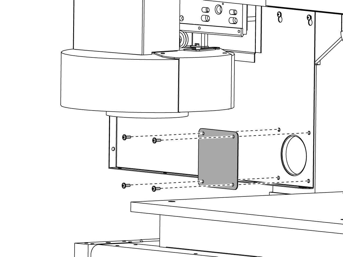
  • Remove the small cover plate.
  • Keep the cover plate.

8

  • For the subsequent steps, install the screws loosely. Tighten the screws after you install all the parts.
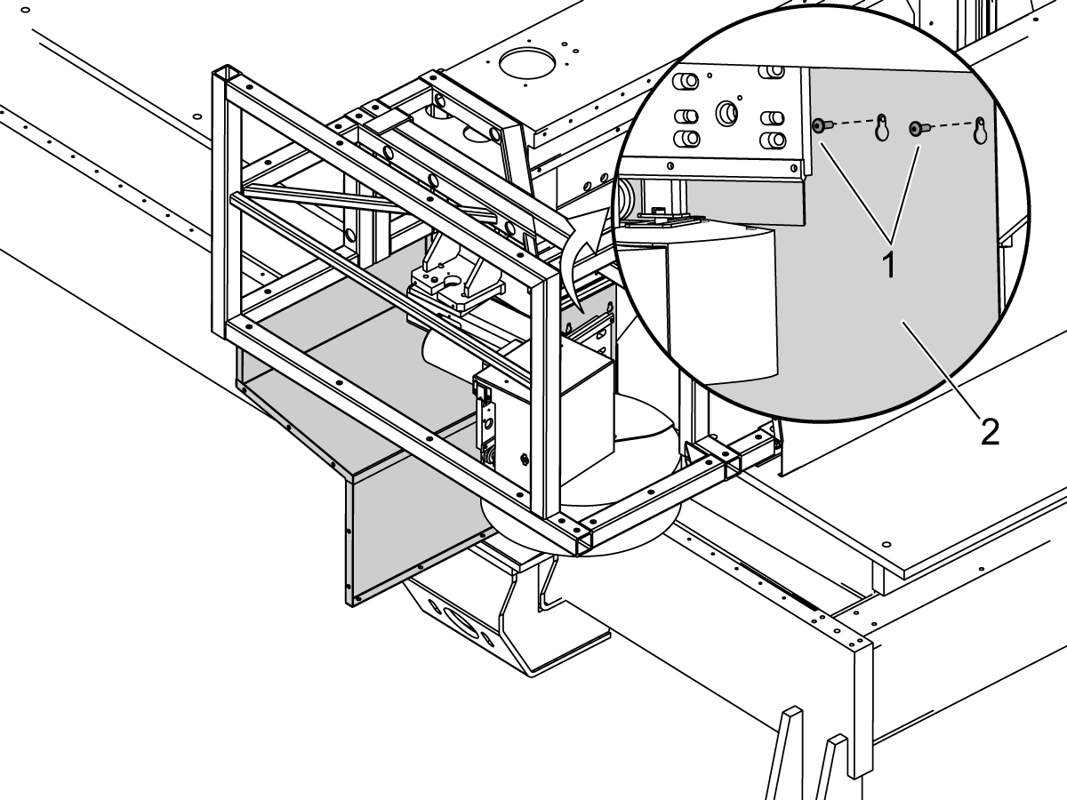
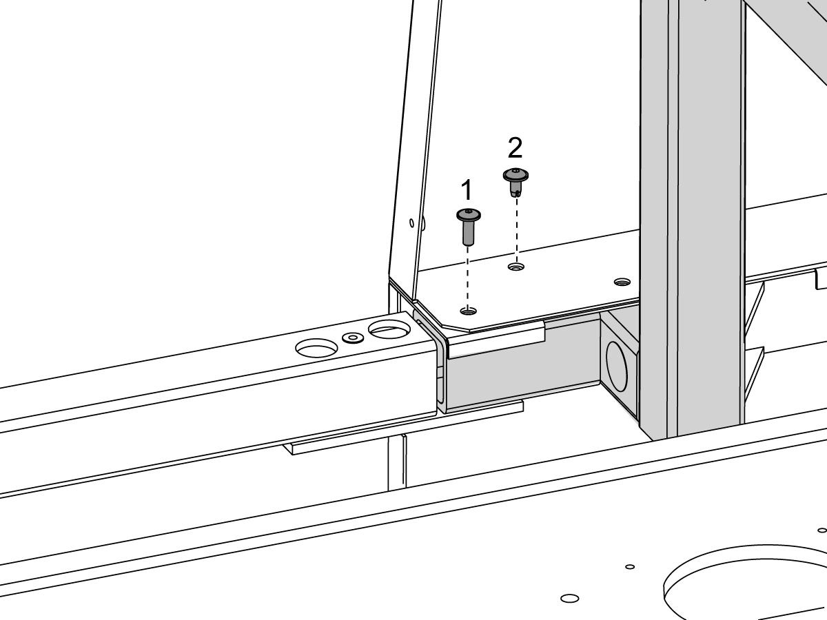
  • Install the (2) 1/4-20 x 1/2" button head cap screws (BHCS) [1]. Hang the first cover piece [2] over the screws.

9

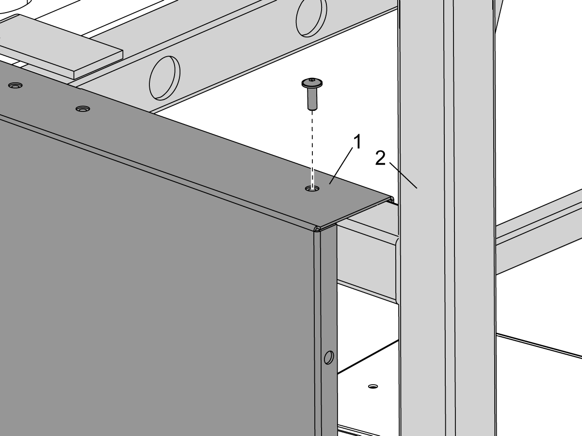
  • In some of the subsequent steps, you attach an enclosure piece [1] to the frame [2]. Use the 1/4-20 x 3/4" BHCS for those steps.

10

  • In other subsequent steps, you attach (2) enclosure pieces together [1]. Use the shorter 1/4-20 x 1/2" BHCS for those steps.

11

  • In some positions, an enclosure piece attaches to the frame with the long 1/4-20 x 3/4" BHCS [1]. And the same enclosure piece attaches to another enclosure piece with the shorter 1/4-20 x 1/2" BHCS [2].

12

  • Get the cover plate you removed in step 6. Install the cover plate with the (4) 1/4-20 x 3/4" BHCS.

13

  • Install the next enclosure piece.

14

  • Use the flanges [1] to hang the next enclosure piece over the frame piece [2].
  • Do not install the screws at this time.

15

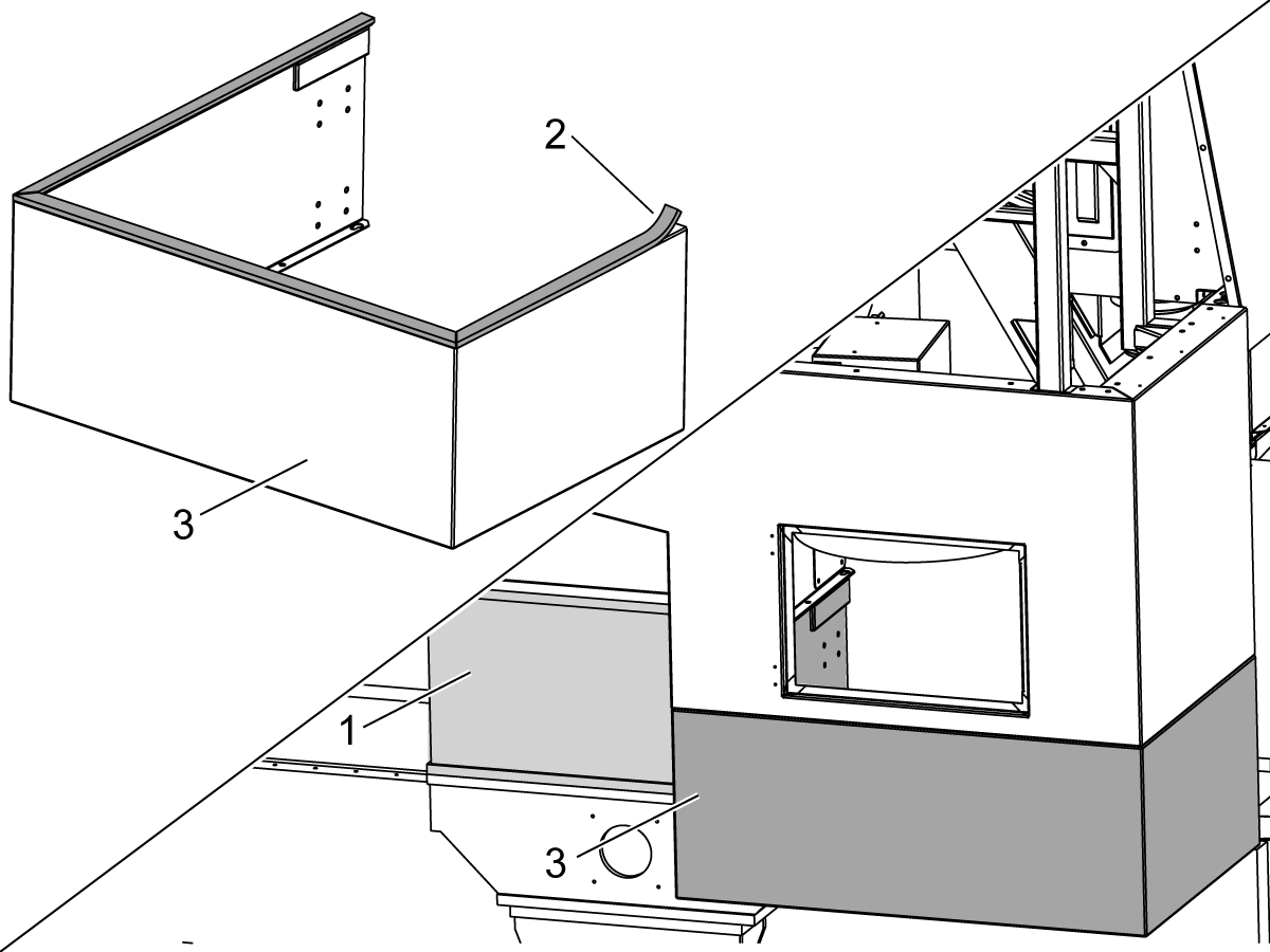
  • Note: Machines with the 6.00" (152 mm) or 24" (610 mm) riser option [1] have one more enclosure piece [3]. Apply the foam tape [2] to the top of the enclosure piece [3]. Then attach the enclosure piece [3]. This image shows the 24" (610 mm) riser option.

16

  • Install the next enclosure piece

17

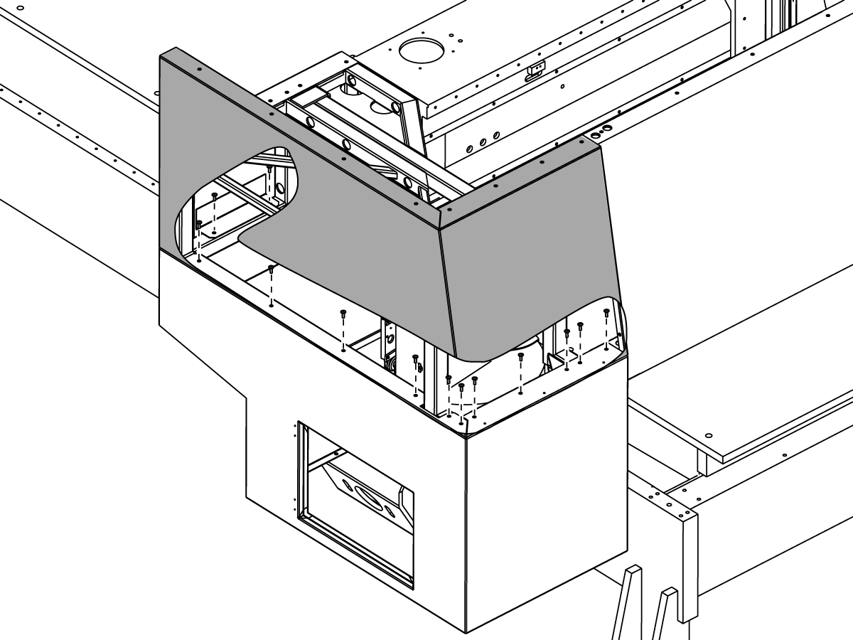
  • Attach the (2) enclosure pieces to the frame. Use the 1/4-20 x 3/4" BHCS..

18

  • Apply foam tape [1] to the next enclosure piece. Then install the enclosure piece [2]..

19

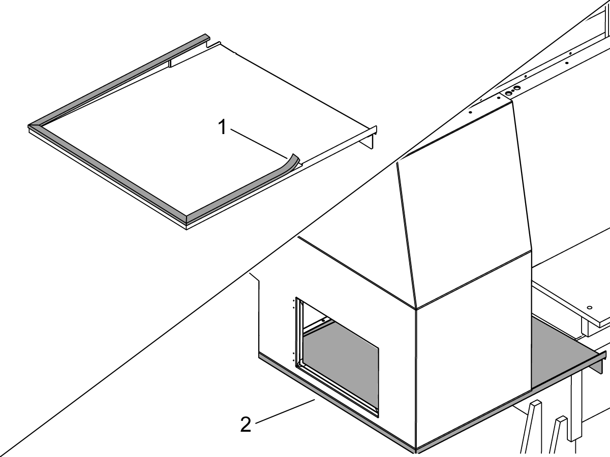
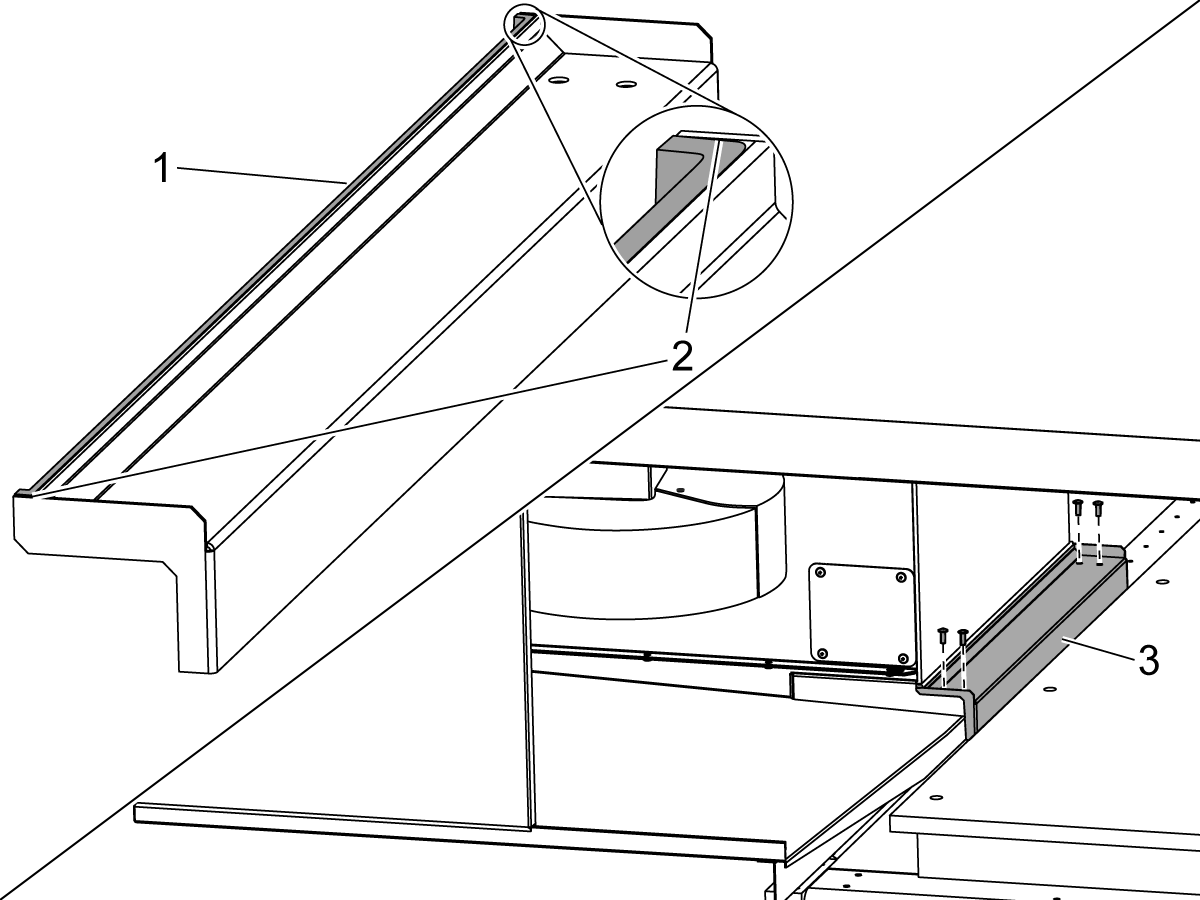
  • Apply foam tape to the drip tray as shown [1]. Extend the foam tape onto the small inner flanges [2].
  • Install the drip tray [3] with the (4) 1/4-20 x 3/4" BHCS.
  • Tighten all of the screws for all of the enclosure pieces.

20

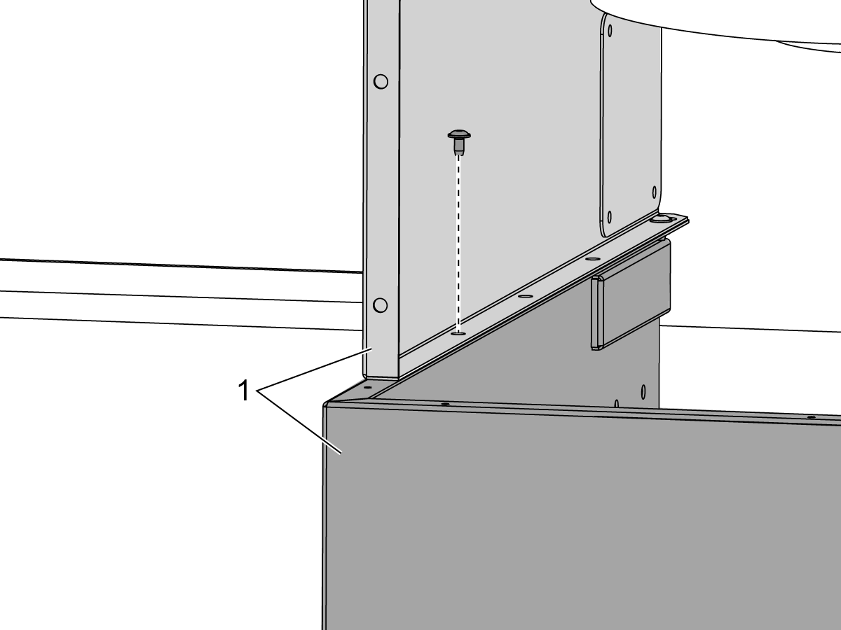
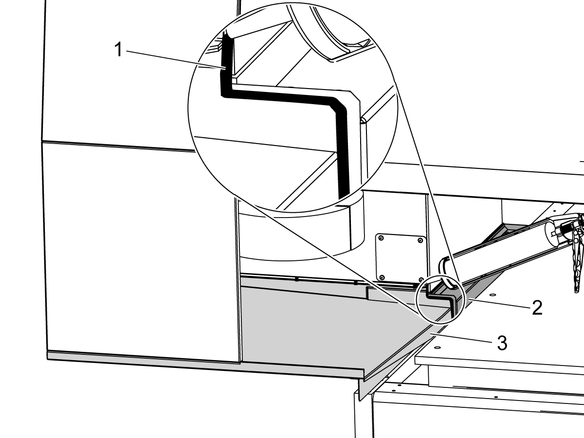
  • Apply Sikaflex construction sealant (or equivalent) [1] to the space between the drip tray [2] and the bottom enclosure piece.

Caution: Coolant leakage can occur through all of the spaces between the enclosure pieces. Apply Sikaflex construction sealant (or equivalent) to all of these spaces.

21

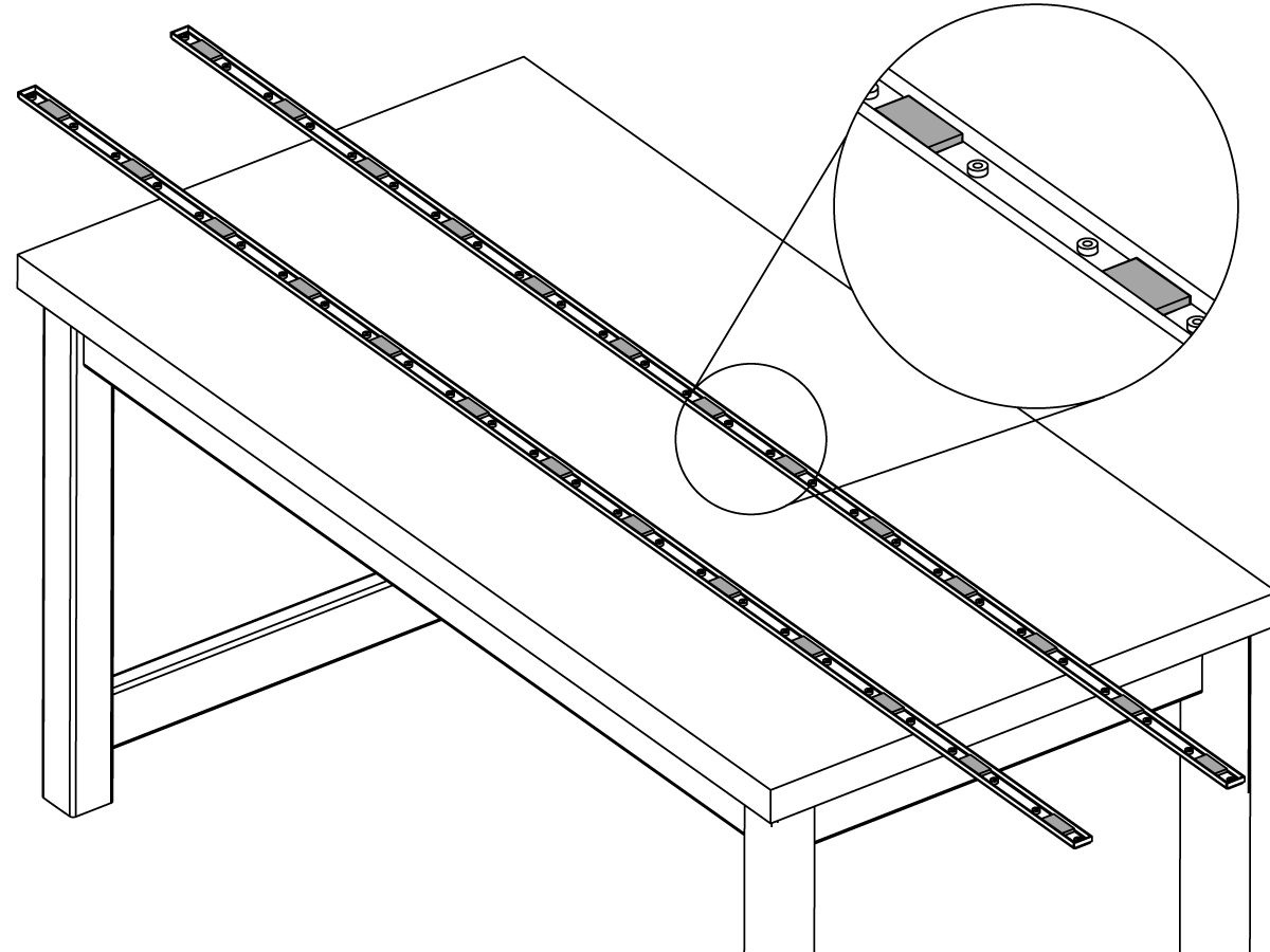
  • Put the magnets on the (2) brackets at every other space.

22

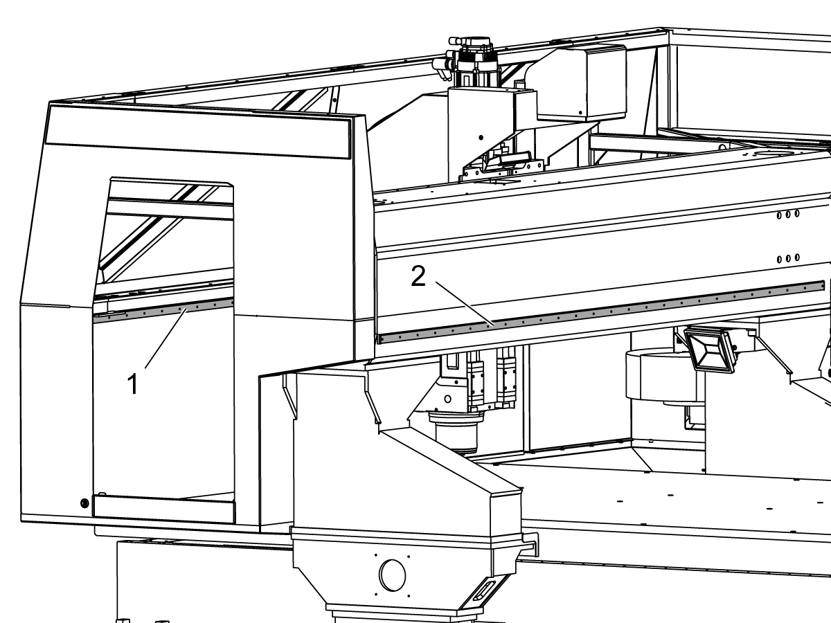
  • Put the brackets with the magnets in these positions:
  • on the inner surface of the front of the enclosure [1]
  • onto the back of the bridge [2]

. Caution: The magnets pull the brackets onto the bridge with strong force. Do not put your fingers between brackets and the bridge or you may injure your fingers.

23

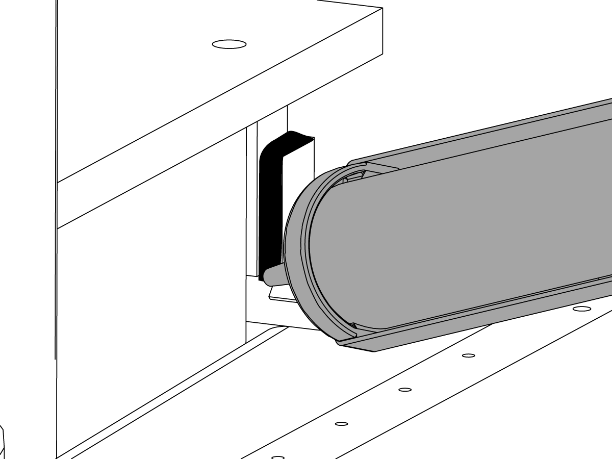
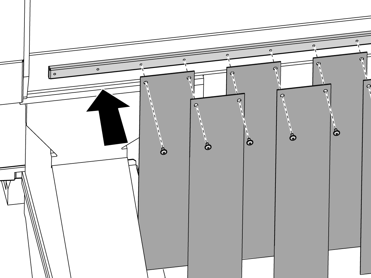
  • Attach the vinyl flaps to the brackets. Use the 1/4-20 x 1/2" BHCS.

24

  • Move the brackets up or down to adjust the distance of the flaps from the table.


Safety Sensors - Installation

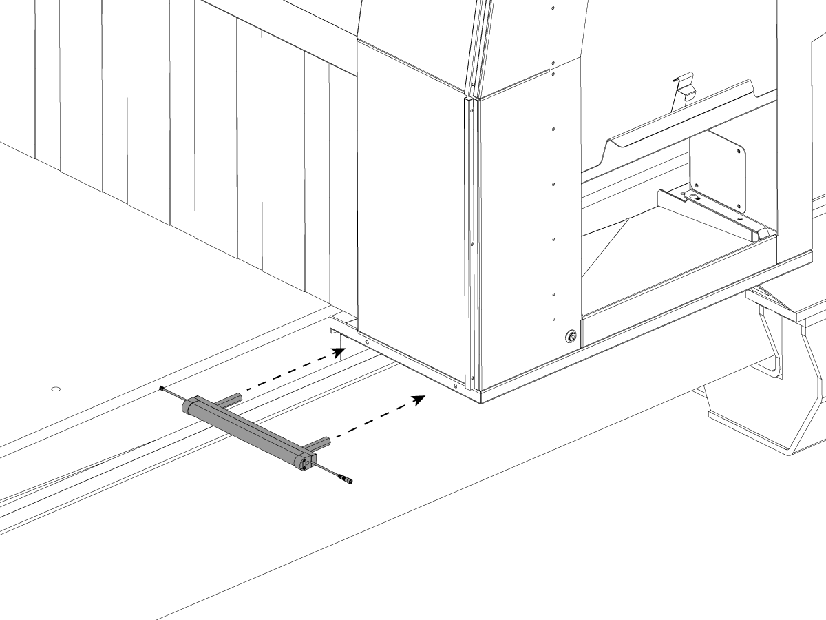
1

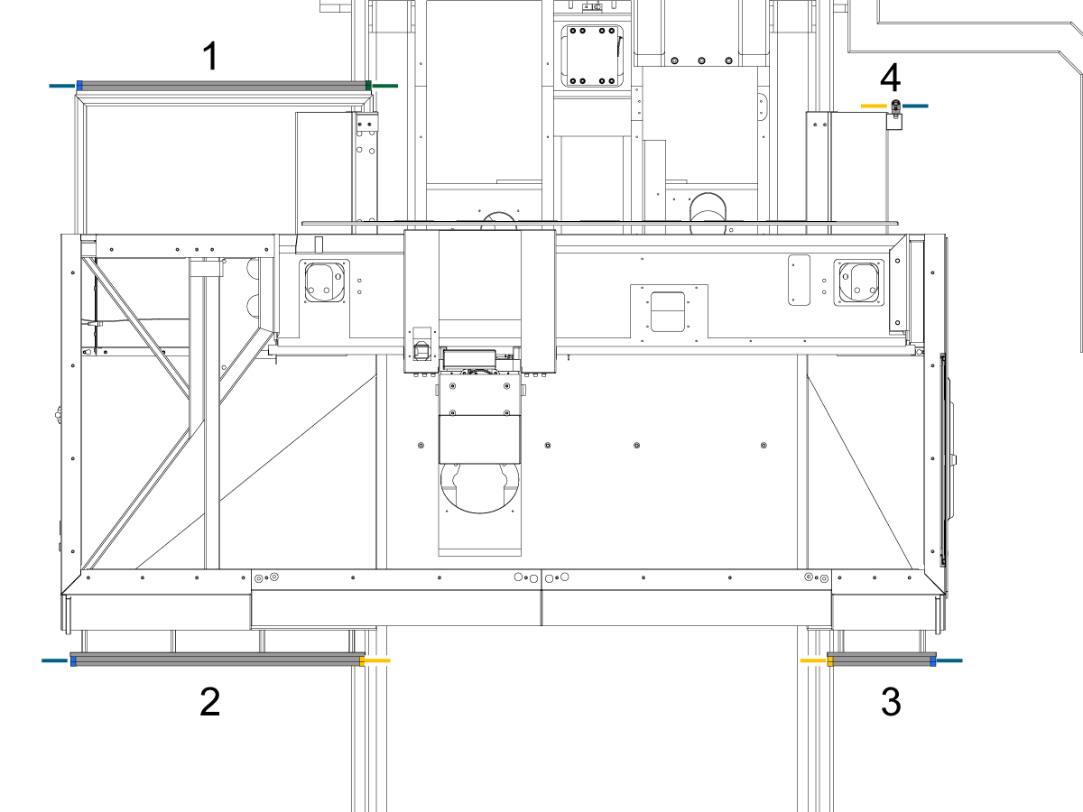
  • Image shows how the Safety Sensors are oriented on the machine. The safety sensors are labeled 1-4.

Note: The sizes of each sensor and the locations on the machine.

  • Each Sensor has two endcaps/connections, a female endcap and a male endcap. Sensor #4 has a male endcap and a terminating endcap.
  • It is important to note the orientation of the male outputs versus the female outputs. This can also be seen in Step 4.
  • Male outputs are generally on the outer sides of the machine. Any writing or labels on the bumpers need to be facing towards the ground.

2

  • Install Corner 1 sensor as shown

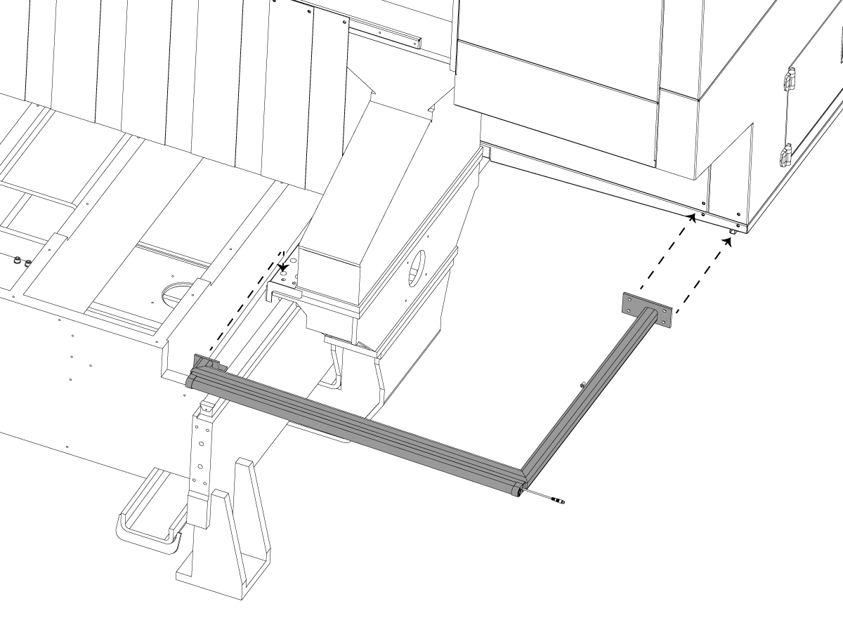
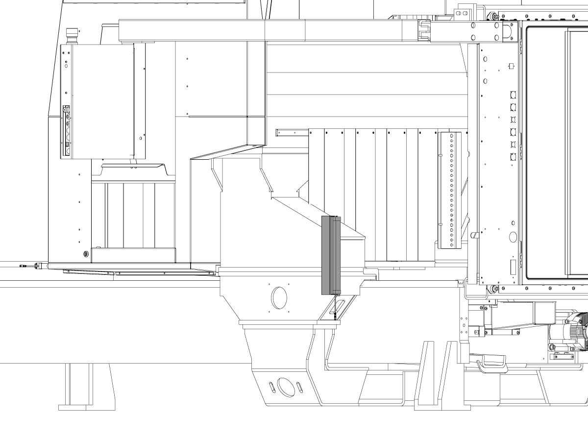
3

  • Install Corner 2 Sensor as shown 

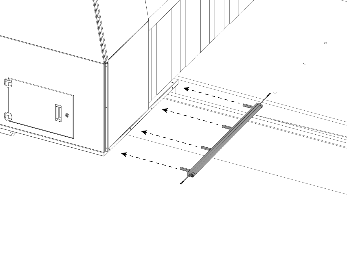
4

  • Install Corner 3 Sensor as shown 

5

  • Corner 4 sensors is per installed.

 Note: orientation of the Endcaps, the length of sensors, and the orientation of the bumpers

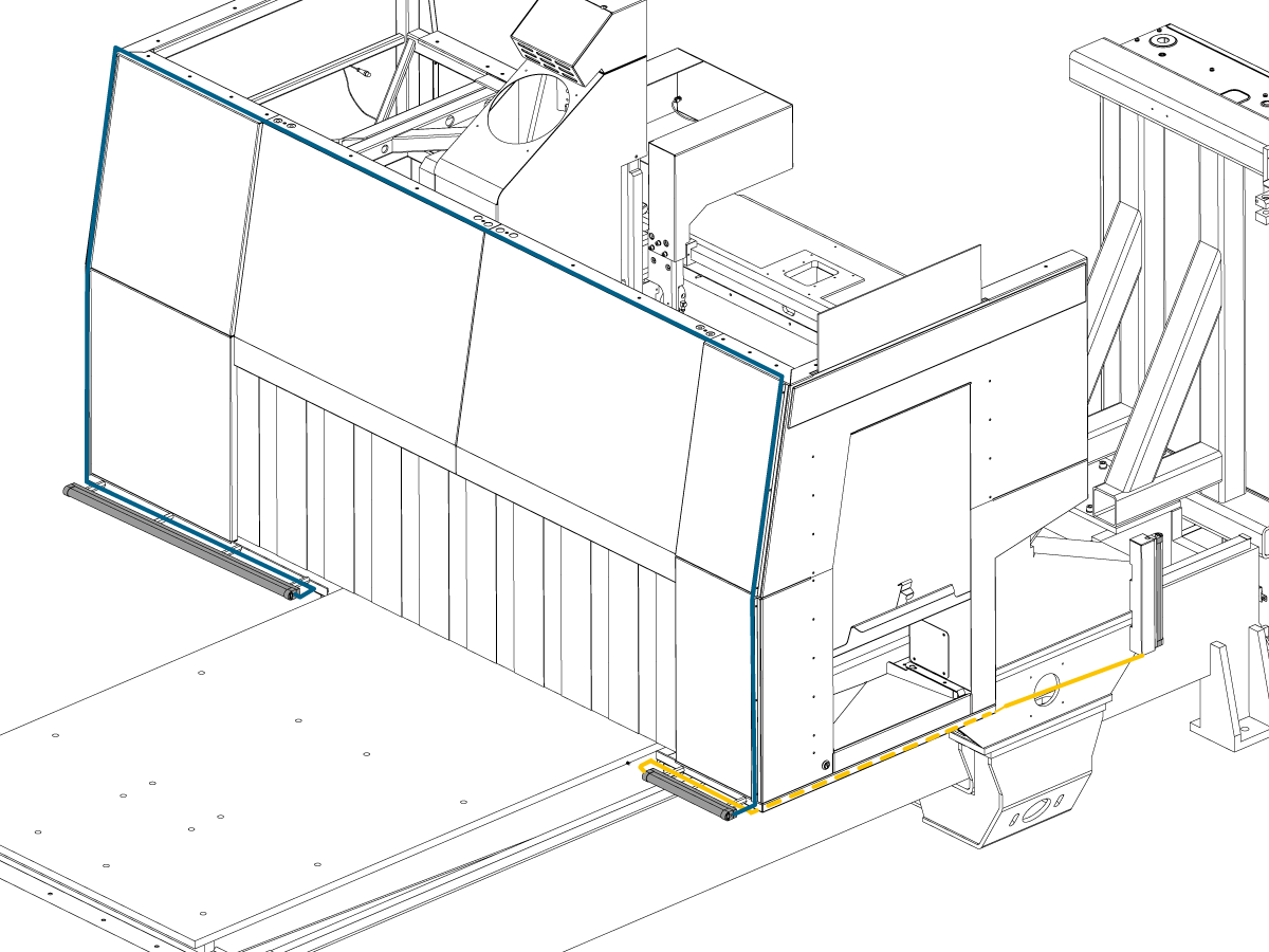
Safety Sensors - Cable Routing and Testing

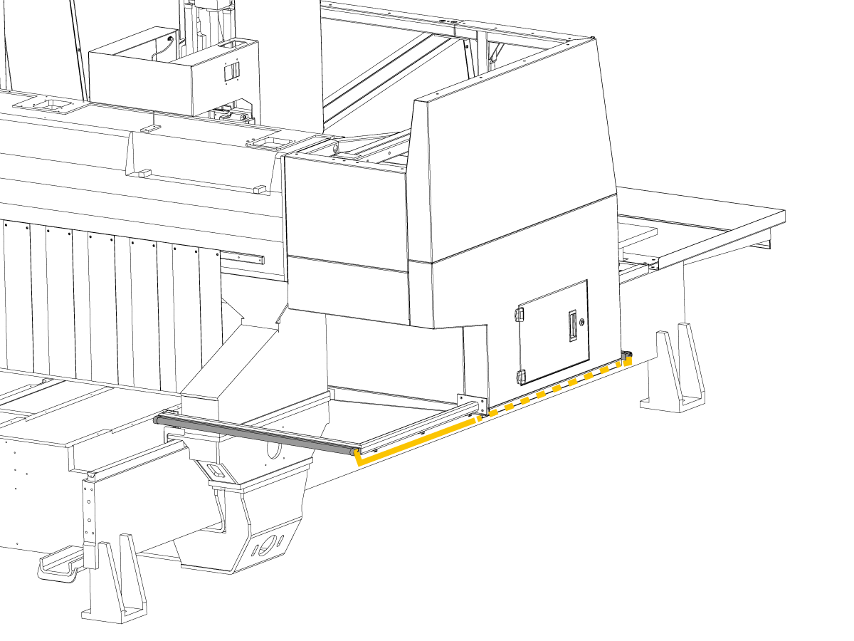
1

  • Connect sensor cables and route through the machine as shown 
  • Use Cable ties and clamps to maintain the cleanliness of the cables.
  • The Enclosure Panels on Corners 2-3 have channels to route saftey sensor cables up through.
  • Use these channels to reduce visable wires.

Leveling

1

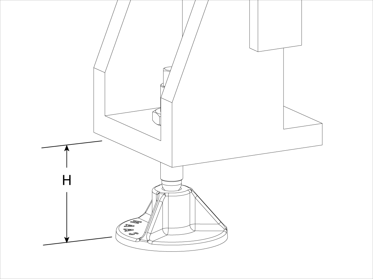
  • Adjust the leveling screws to raise the machine 3 1/2" (H) from the floor.

2

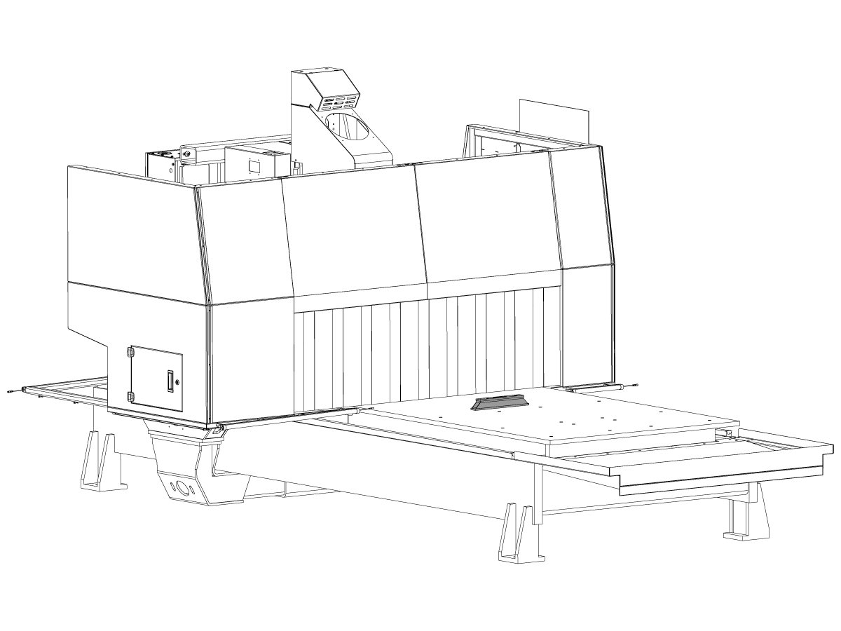
  • Place the bubble level on the center of the table parallel to the Y-Axis. Adjust the leveling screws to level the table.

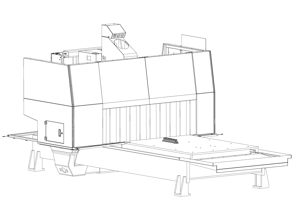
3

  • Place a bubble level on the center of the table parallel to the X-Axis. Adjust the leveling screws to level the table.

4

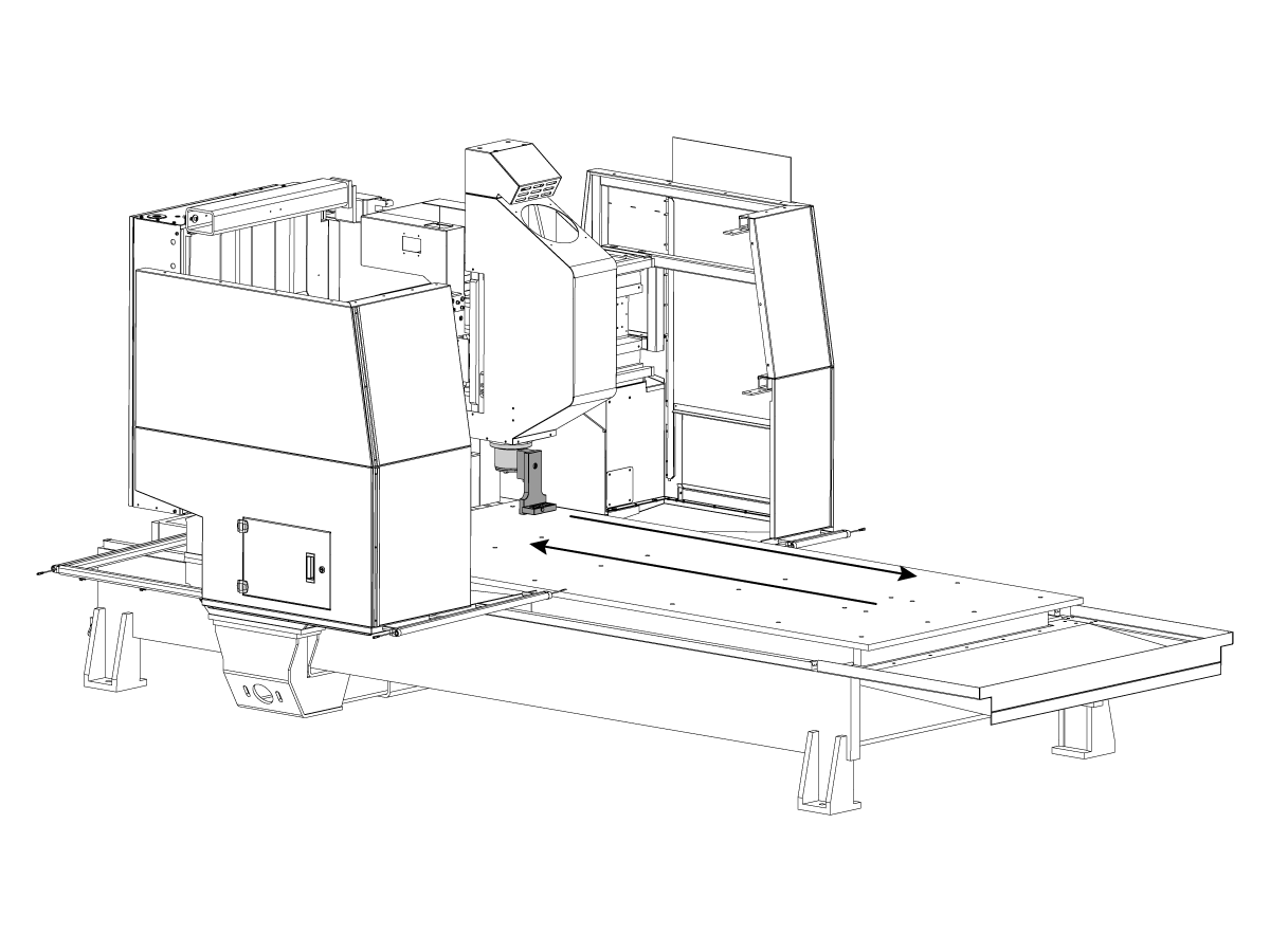
  • Attach the level tool to the spindle, with the tool facing as shown in the image.
  • T-2181: CNC DUAL LEVELING TOOL
  • T-2192: LEVELING ADAPTER UMC-750
  •  Jog the X axis to either end of the base and read the measurements.
  • Adjust the leveling screws as need be to raise or lower a corner of the base until the bubble closely match end to end.
  • Readings are NTE 0.0002" over full travel.

Recently Viewed Items

You Have No Recently Viewed Items Yet

Feedback
Haas Logo

Haas Delivered Price

This price includes shipping cost, export and import duties, insurance, and any other expenses incurred during shipping to a location in France agreed with you as a buyer. No other mandatory costs can be added to the delivery of a Haas CNC Product.

KEEP UP WITH THE LATEST HAAS TIPS AND TECHNOLOGY...

Sign up now!   

HAAS TOOLING ACCEPTS THE FOLLOWING:

  • Service & Support
  • Owners
  • Request Service
  • Operator Manuals
  • Haas Parts
  • Rotary Repair Request
  • Pre-Install Guides
  • Shopping Tools
  • Build & Price a New Haas
  • Available Inventory
  • The Haas Price List
  • CNCA Financing
  • About Haas
  • Accessibility Statement
  • DNSH Statement
  • Export Compliance
  • Careers
  • Certifications & Safety
  • Contact Us
  • History
  • Terms & Conditions
  • Haas Tooling Terms & Conditions
  • Privacy
  • Warranty
  • Haas Community
  • Haas Certification Program
  • Haas Motorsports
  • Gene Haas Foundation
  • Haas Technical Education Community
  • Events
  • Join the Conversation
  • Facebook
  • X
  • Flickr
  • YouTube
  • LinkedIn
  • Instagram
  • TikTok
© 2026 Haas Automation, Inc – CNC Machine Tools

This site is protected by reCAPTCHA and the Google Privacy Policy and Terms of Service apply.

2800 Sturgis Rd., Oxnard, CA 93030
Toll Free: (888) 817-4446 / Fax: 805-278-8554