My Haas Welcome,
!
Haas Tooling MyHaas/HaasConnect Sign In Register Haas Tooling MyHaas/HaasConnect Sign Out Welcome, My Machines Latest Activity My Quotes My Account My Users Sign Out
Find Your Distributor
  1. Select Language
    1. English
    2. Deutsch
    3. Español - ES
    4. Español - MX
    5. Français
    6. Italiano
    7. Português
    8. Český
    9. Dansk
    10. Nederlands
    11. Magyar
    12. Polski
    13. Svenska
    14. Türkçe
    15. 中文
    16. Suomi
    17. Norsk
    18. الإنجليزية
    19. български
    20. Hrvatski
    21. Ελληνικά
    22. Română
    23. Slovenský
    24. Slovenščina
    25. 한국어
    26. 日本語
    27. Українська
  • machines Main Menu
    • Vertical Mills
      Vertical Mills
      Vertical Mills View All
      • Vertical Mills
      • VF Series
      • Universal Machines
      • VR Series
      • VP-5 Prismatic
      • Pallet-Changing VMCs
      • Mini Mills
      • Mold Machines
      • High-Speed Drill Centers
      • Drill/Tap/ Mill Series
      • Toolroom Mills
      • Pocket Mill
      • Compact Mills
      • Gantry Series
      • SR Sheet Routers
      • Extra-Large VMC
      • Double-Column Mills
      • 3+2 Positioning Machines
    • Multi-Axis Solutions
      Multi-Axis Solutions
      Multi-Axis Solutions View All
      • Multi-Axis Solutions
      • Y-Axis Lathes
      • 5-Axis Mills
    • Lathes
      Lathes
      Lathes View All
      • Lathes
      • ST Series
      • Dual-Spindle
      • Box Way Series
      • Toolroom Lathes
      • Chucker Lathe
      • Pocket Lathe
      • Haas Bar Feeders
    • Horizontal Mills
      Horizontal Mills
      Horizontal Mills View All
      • Horizontal Mills
      • 50-Taper
      • 40-Taper
    • Rotaries & Indexers
      Rotaries & Indexers
      Rotaries & Indexers View All
      • Rotaries & Indexers
      • Rotary Tables
      • Indexers
      • 5-Axis Rotaries
      • Extra-Large Rotaries
    • Special Series
      Special Series
      Special Series View All
      • Special Series
      • EU_Series_Redirect
    • Automation Systems
      Automation Systems
      Automation Systems View All
      • Automation Systems
      • Mill Automation
      • Lathe Automation
      • Automatic Parts Loaders
      • Automation Models
    • Desktop Machines
      Desktop Machines
      Desktop Machines View All
      • Desktop Machines
      • Desktop Mill
      • Desktop Lathe
      • Control Simulator, Standard
      • Control Simulator, Premium
    • Shop Equipment
      Shop Equipment
      Shop Equipment View All
      • Shop Equipment
      • Knee Mill
      • Haas Manual Lathes
      • Haas Saws
    • Fabrication Machines
      Fabrication Machines
      Fabrication Machines View All
      • Fabrication Machines
      • Laser Cutting Machines
      • CNC Press Brakes
    • QUICK LINKS Special Series  Special Series 
      EU SERIES EU SERIES BUILD & PRICE | PRICE LIST BUILD & PRICE | PRICE LIST In-Stock Machines In-Stock Machines WHAT’S NEW WHAT’S NEW YOUR FIRST CNC YOUR FIRST CNC
      SHOPPING TOOLS
      • Build & Price a Haas
      • Price List
      • Available Inventory
      • CNCA Financing
      WANT TO TALK TO SOMEONE?

      A Haas Factory Outlet (HFO) can answer your questions, and walk you through your best options.

      CONTACT YOUR DISTRIBUTOR >
  • Options Main Menu
    • The Haas Control Value Option Packages
      Value Option Packages
      Value Option Packages View All
      • Value Option Packages
    • Product Image Spindles
      Spindles
      Spindles View All
      • Spindles
    • Product Image Tool Changers
      Tool Changers
      Tool Changers View All
      • Tool Changers
    • Product Image 4th- | 5th-Axis
      4th- | 5th-Axis
      4th- | 5th-Axis View All
      • 4th- | 5th-Axis
    • Product Image Turrets & Live Tooling
      Turrets & Live Tooling
      Turrets & Live Tooling View All
      • Turrets & Live Tooling
    • Product Image Probing
      Probing
      Probing View All
      • Probing
    • Haas Chip & Coolant Management Chip & Coolant Management
      Chip & Coolant Management
      Chip & Coolant Management View All
      • Chip & Coolant Management
    • The Haas Control The Haas Control
      The Haas Control
      The Haas Control View All
      • The Haas Control
    • Product Image Product Options
      Product Options
      Product Options View All
      • Product Options
    • Product Image Tooling & Fixturing
      Tooling & Fixturing
      Tooling & Fixturing View All
      • Tooling & Fixturing
    • Product Image Workholding
      Workholding
      Workholding View All
      • Workholding
    • Product Image 5-Axis Solutions
      5-Axis Solutions
      5-Axis Solutions View All
      • 5-Axis Solutions
      • 5 Easy Steps to 5-Axis
    • QUICK LINKS Special Series  Special Series 
      EU SERIES EU SERIES BUILD & PRICE | PRICE LIST BUILD & PRICE | PRICE LIST In-Stock Machines In-Stock Machines WHAT’S NEW WHAT’S NEW YOUR FIRST CNC YOUR FIRST CNC
      SHOPPING TOOLS
      • Build & Price a Haas
      • Price List
      • Available Inventory
      • CNCA Financing
      WANT TO TALK TO SOMEONE?

      A Haas Factory Outlet (HFO) can answer your questions, and walk you through your best options.

      CONTACT YOUR DISTRIBUTOR >
  • Why Haas Main Menu
      Discover the Haas Difference
    • Why Haas
    • MyHaas
    • Education Community
    • Industry 4.0
    • Haas Certification
    • Customer Testimonials
  • Service Main Menu
      Welcome to Haas Service
      SERVICE HOME Operator’s Manuals How-To Procedures Troubleshooting Guides Preventive Maintenance Haas Parts Haas Tooling Videos
  • Videos Main Menu
  • Main Menu
    • View All
    • View All
    • View All
    • View All
      • HTEC Curriculum Support
      • Haas Value Option Packages (VOP) Journey
    • View All
      • Haas 10 kg Cobot Package
      • Cobot Kits
      • DC-1 Drill Center
      • CNC Sales News
      • Do More With Your Haas
    • View All
    • View All
      • contact-us-test
      • 4 - AUTOMATION SYSTEMS
      • Carousel-V2
      • expert test
      • Demo_Day_Trident-test
      • Link Test
      • image-sale-tag-test
      • article-list-test
      • Haas 25 kg Robot Package
      • test-algolia-page
    • View All
    • View All
    • View All
    • View All
      • calc-test
    • View All
    • QUICK LINKS Special Series  Special Series 
      EU SERIES EU SERIES BUILD & PRICE | PRICE LIST BUILD & PRICE | PRICE LIST In-Stock Machines In-Stock Machines WHAT’S NEW WHAT’S NEW YOUR FIRST CNC YOUR FIRST CNC
      SHOPPING TOOLS
      • Build & Price a Haas
      • Price List
      • Available Inventory
      • CNCA Financing
      WANT TO TALK TO SOMEONE?

      A Haas Factory Outlet (HFO) can answer your questions, and walk you through your best options.

      CONTACT YOUR DISTRIBUTOR >
  • Haas Tooling Main Menu
  • Haas Service Parts Main Menu

My Haas Welcome,
!
Haas Tooling MyHaas/HaasConnect Sign In Register Haas Tooling MyHaas/HaasConnect Sign Out Welcome, My Machines Latest Activity My Quotes My Account My Users Sign Out
Find Your Distributor
  1. Select Language
    1. English
    2. Deutsch
    3. Español - ES
    4. Español - MX
    5. Français
    6. Italiano
    7. Português
    8. Český
    9. Dansk
    10. Nederlands
    11. Magyar
    12. Polski
    13. Svenska
    14. Türkçe
    15. 中文
    16. Suomi
    17. Norsk
    18. الإنجليزية
    19. български
    20. Hrvatski
    21. Ελληνικά
    22. Română
    23. Slovenský
    24. Slovenščina
    25. 한국어
    26. 日本語
    27. Українська
×

Search Results

Web Pages

Images

    • <
    • 1
    • >

EC-400/500, VC-400 Pallet Receiver & Clamp Assembly - AD0619

Service Home How To Procedures EC-400/500, VC-400 Pallet Receiver & Clamp Assembly - AD0619

EC-400/500, VC-400 Pallet Receiver & Clamp Assembly - AD0619

- Jump to Section - 1. Introduction 2. Conveyor and Sheet Metal Removal (5 steps) 3. Depressurize the HPU (2 steps) 4. Removal (3 steps) 5. Installation (16 steps) 6. RECEIVER VERIFICATIONS: (5 steps) 7. Repressurize the HPU (5 steps) 8. PALLET VERIFICATIONS: (6 steps) Back to Top
Recently Updated Last updated: 08/15/2025

EC-400/500, VC-400 Pallet Receiver & Clamp Assembly - Installation


AD0619

Revision B - 08/2025

Introduction

This procedure is designed to resolve leak issues observed on the 4th-Axis of the following Haas machines:

  • EC-400
  • EC-500
  • EC-500/50
  • VC-400/SS

 NOTE: For machines built from 01/19/2022 to 08/15/2025, if the Receiver and Clamp Assembly is being replaced due to coolant intrusion, see the EC/VC Rotary Troubleshooting Guide symptom table and/or contact Haas Service for more infromation. 

 Note: For additional details regarding the required service kit, please contact Haas Service directly.

Minimum requirements:

  • This kit is only available for reboot EC-400/500 and all VC-400's. Refer to the EC Identification Document for assistance on determining if the machine is a reboot machine.

 NOTE: For the reboot EC-400's 4th Axis assemblies that were built before 5/2022 or have not upgraded to the new design, refer to EC-400 4th Axis Receiver Rebuild.

This procedure applies to the following kit:

  • 93-3465 PALLET RECEIVER & CLAMP ASSY EC-400/500
  • 93-3464 PALLET RECEIVER & CLAMP ASSY VC-400 

 NOTE: This procedure also applies to 93-3464 PALLET RECEIVER & CLAMP ASSY VC-400. While there may be minor variations in the process, the steps outlined here serve as a general guideline.

NOTE: The kit is shipped with a protective anti-rust grease coating. If this grease comes into contact with the internal or external seals, it must be cleaned off thoroughly. After cleaning, apply silicone grease to the seals to ensure proper sealing performance and longevity.

Conveyor and Sheet Metal Removal

1

The conveyor will need to be removed in order to complete this procedure. In order to remove the conveyor, certain sheet metal will need to be removed so the conveyor can slide out.

If the conveyor is not removed it will be very difficult to remove the hydraulic manifold later in the procedure. 

Refer to the following steps to identify which sheet metal to remove. 

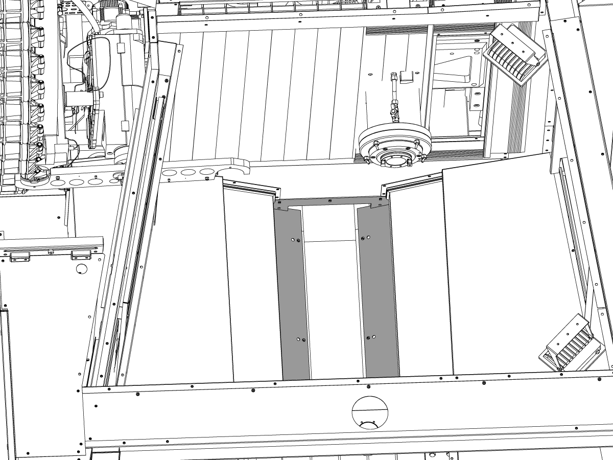
2

Remove the following sheet metal in order to remove the conveyor.

The following image depicts the sheet metal that needs to be removed near the spindle side of the conveyor channel.

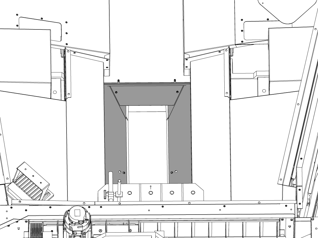
3

Remove the following sheet metal in order to remove the conveyor.

The following image depicts the sheet metal that needs to be removed near the APC side of the conveyor channel.

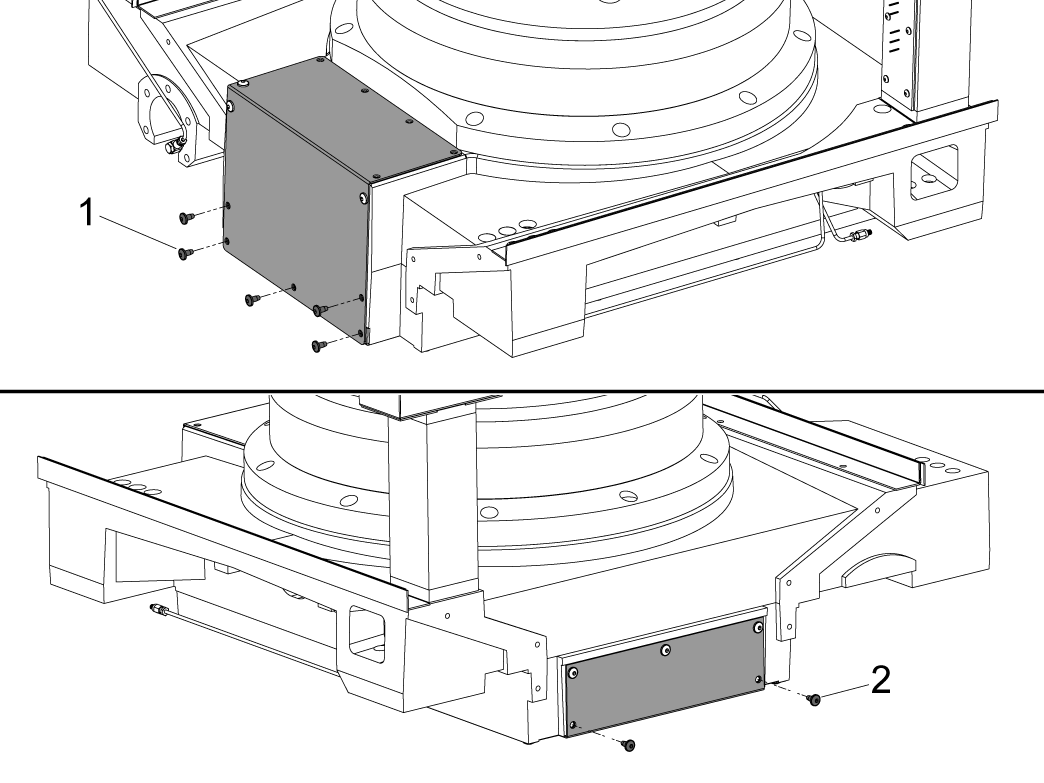
4

To remove the cover that protects the clamp and unclamp manifold first remove the bolts noted as [1] and [2] on the sides of the saddle.

Do not remove the sheet metal covers, keep the remaining bolts in place.

5

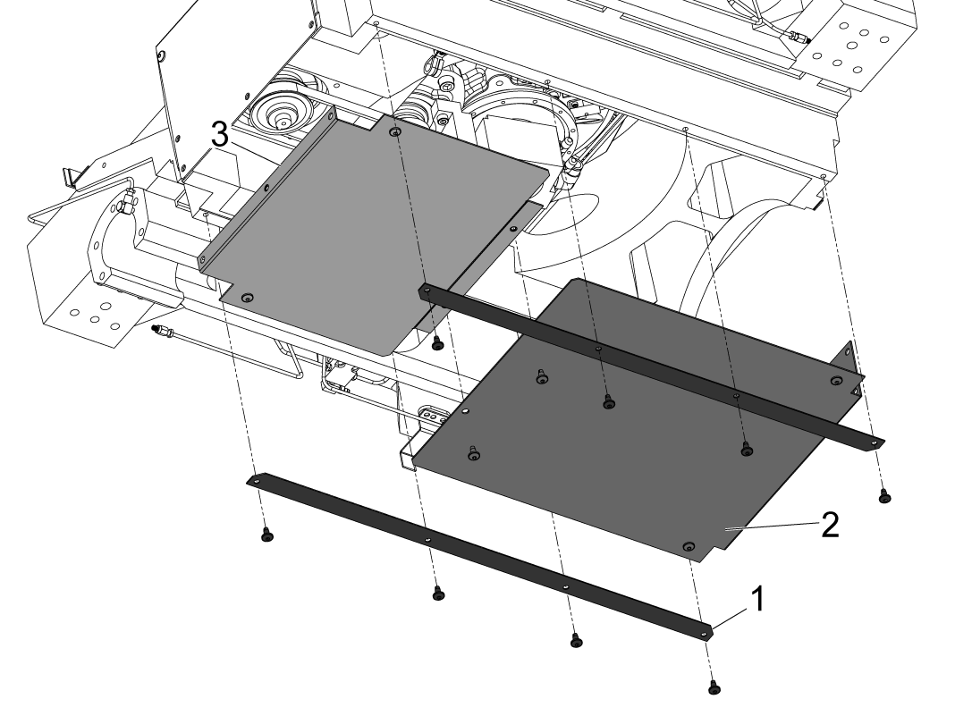
Remove the sheet metal depicted in order to expose the hydraulic manifold. 

Remove the two long strips [1] holding the covers [2] and [3] in place.

Remove the cover denoted as [2] first, then the panel denoted as [3] next.

NOTE: These panels are wedged between the sheet metal on the sides of the saddle in which you removed the bolts in the previous step.

Depressurize the HPU

1

Zero return the B-Axis before depressurizing the HPU

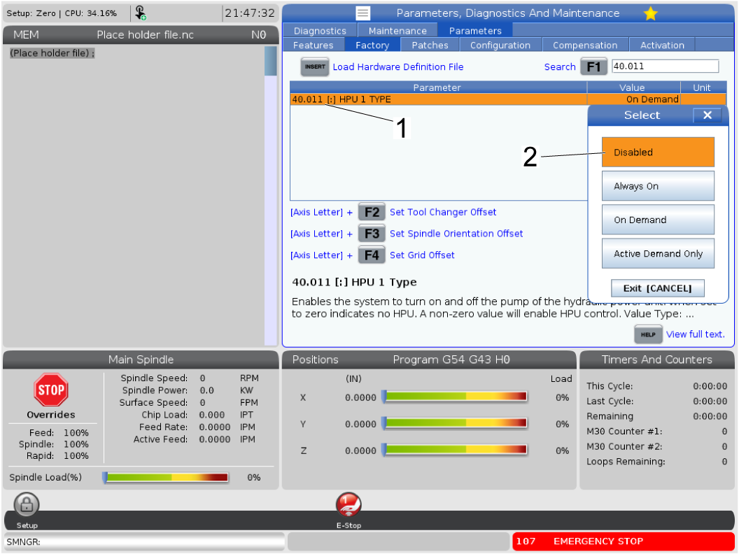
Set parameter 40.011 HPU 1 TYPE [1] to DISABLED [2]. 

 NOTE: Parameter 40.011 HPU 1 TYPE will need to be set to DISABLED in order for the depressurize page to work. If it is set to ALWAYS ON or ON DEMAND the HPU will not depressurize.

2

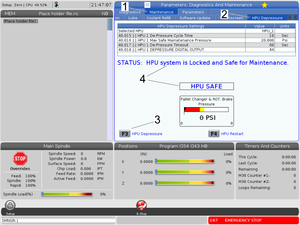
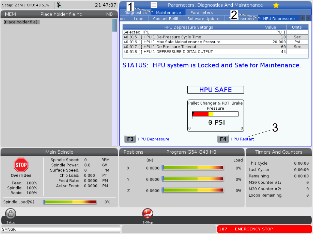
Depressurize the HPU using the HPU DEPRESSURE page.

Press [DIAGNOSTIC] then navigate to the MAINTENANCE tab [1] then navigate to the HPU DEPRESSURE tab [2]. Press [F3] to depressurize the HPU [3] and the HPU should no longer have pressure in the lines. The text on the screen will display a status that the HPU is safe to use [4]

 NOTE: Parameter 40.011 HPU 1 TYPE will need to be set to DISABLED in order for the depressurize page to work. If it is set to ALWAYS ON the HPU will not depressurize.

Release the brake, press E-stop and place lock-out on the machine.

Removal

1

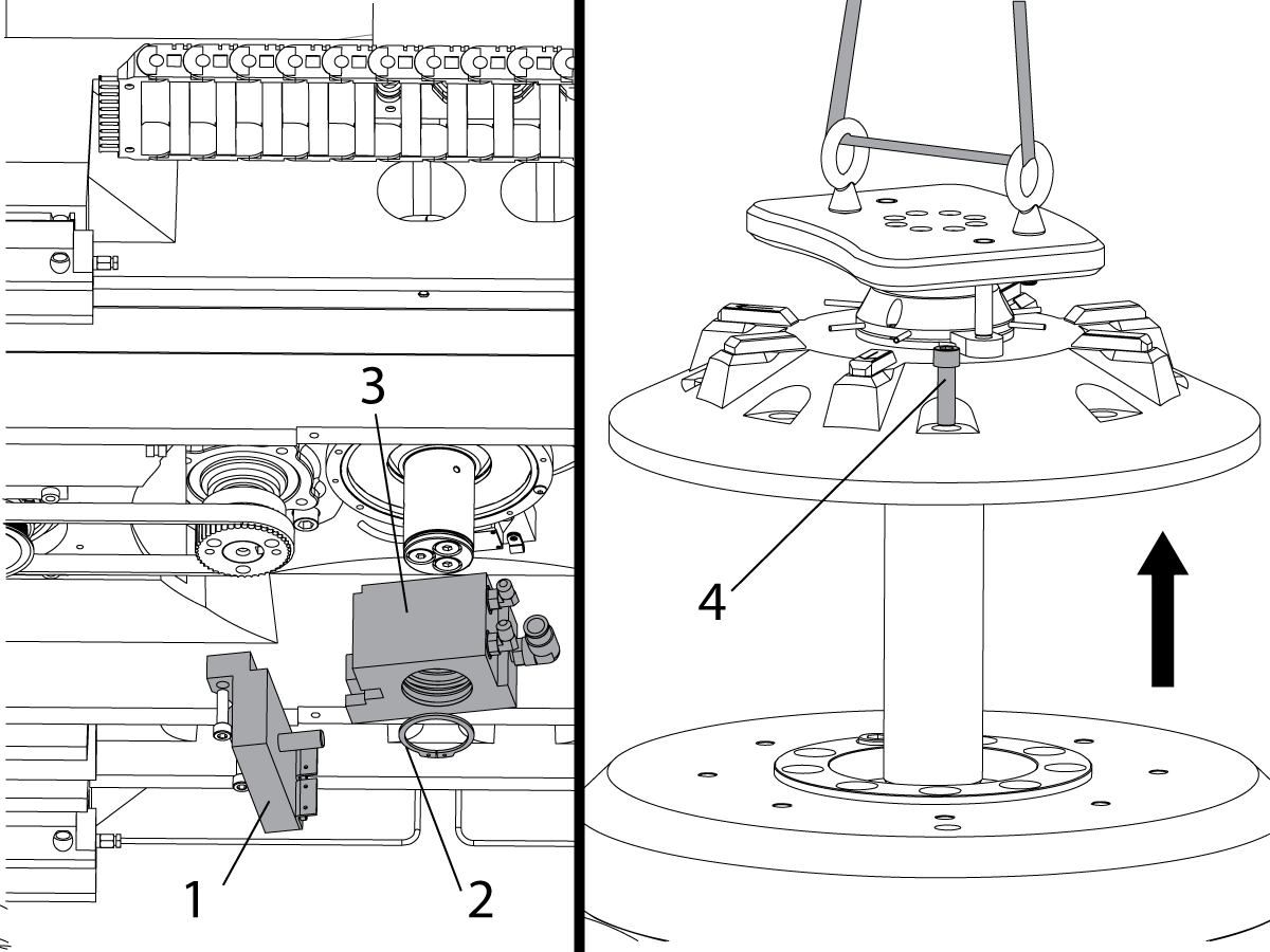
Unbolt and lower the sensor/anti-rotation bracket [1]. Remove the snap ring [2] from the shaft. Lower the block [3] off the shaft.

NOTE: Mark the hydraulic lines, air lines, and fittings on the manifold with zip ties to ease reinstallation later during this procedure.

Install jack bolts [4] under the clamp plate to prevent damage to the piston quad-ring.

Remove the (8) bolts [5] from the receiver.

Install (2) eye bolts in the clamp plate. Use an appropriate lifting strap to raise the receiver from the rotary.

This assembly will weigh approximately 200 lbs.

NOTE: Hydraulic fluid will leak out when the receiver is lifted.

NOTE: Disassemble the receiver assembly and remove the springs as they will be reused later in the procedure. Hydraulic fluid will leak when disassembling the receiver.

2

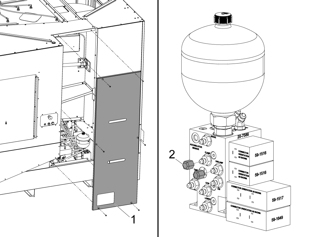
Remove panel [1] to expose the HPU and its manifold block. It is important to cap the clamp, unclamp, and brake fittings [2] on the HPU manifold side in order to proceed with the installation section of this procedure. 

NOTE: Mark the hydraulic lines and fittings on the manifold with zip ties to ease reinstallation later during this procedure.

NOTE: The hydraulic lines will leak fluid when disconnecting them from the manifold, place a plastic bag or rags to maintain a clean machine.

3

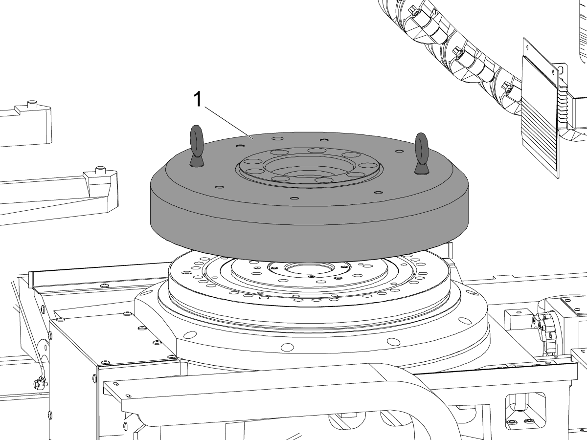
Using 1/2-13 eye bolts safely lift and remove the platter.

This platter weights approximately 200 lbs use the proper lifting apparatus when removing. 

Release the brake and make sure the HPU is depressurized before removing the line. Plug the brake like to prevent leakage. 

 WARNING: IF YOU DO NOT DISENGAGE THE BRAKE AND DISCONNECT THE LINES YOU CAN PERMANENTLY DAMAGE THE BRAKE BY REMOVING THE PLATTER.


Installation

1

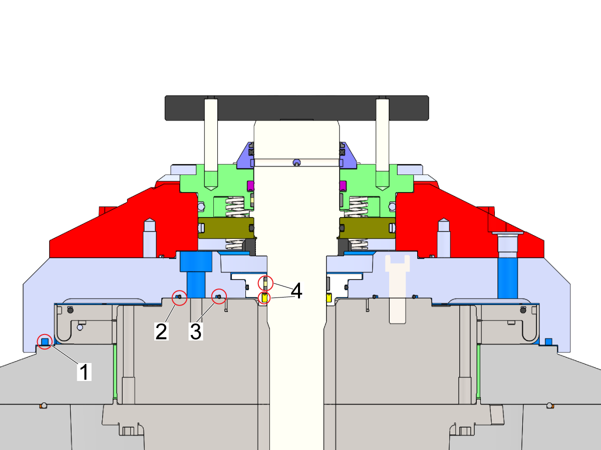
The felt seal has already been installed to the bottom side of the platter denoted as [1], apply a thin layer of tacky grease on the felt seal as well as on the outer diameter of the brake. (5% Moly Grease 99-1792)

Before installing the platter to the brake install 57-0461 O-rings [2] and 57-2144 [3] on the bottom side of the platter. Apply a thin layer of silicon grease to the internal seals [4] on the lower seal gland cap. 

 NOTE: The kit is coated with anti-rust grease before shipping. If this grease is applied to the internal and external seals, please clean them and apply silicon grease to the seals.

NOTE: Applying too much silicon grease may compromise sealing capabilities. 

2

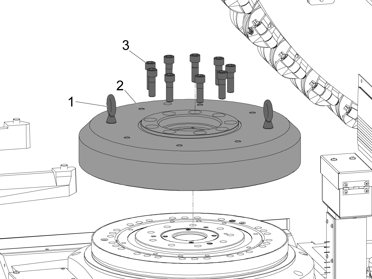
Using 1/2-13 eye bolts [1] safely lower the platter [2] onto the brake assembly. Line up the brake bleed port on the brake with the access hole on the platter.

Loosely install the platter mounting bolts (SHCS M16 X 50 ) [3] these will be re-used from the previous platter assembly.

The platter weighs approximately 200 lbs, use the proper lifting apparatus to safely lift this component. 

3

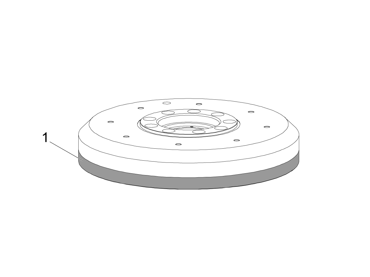
Indicate the platter runout, this is NTE 0.0005 in (0.013mm).

The platter will have a line on the side of the platter, place your indicator on the lower surface [1]. 

Once indicated torque the mounting bolts in star pattern referencing the HAAS TORQUE SPECIFICATION document. 

NOTE: It is recommended to use a dead blow to adjust the runout, if the bake is used to self-center the platter this will not allow the machine to use the depressurize page to drain the HPU.

4

EC-400/500 Machines

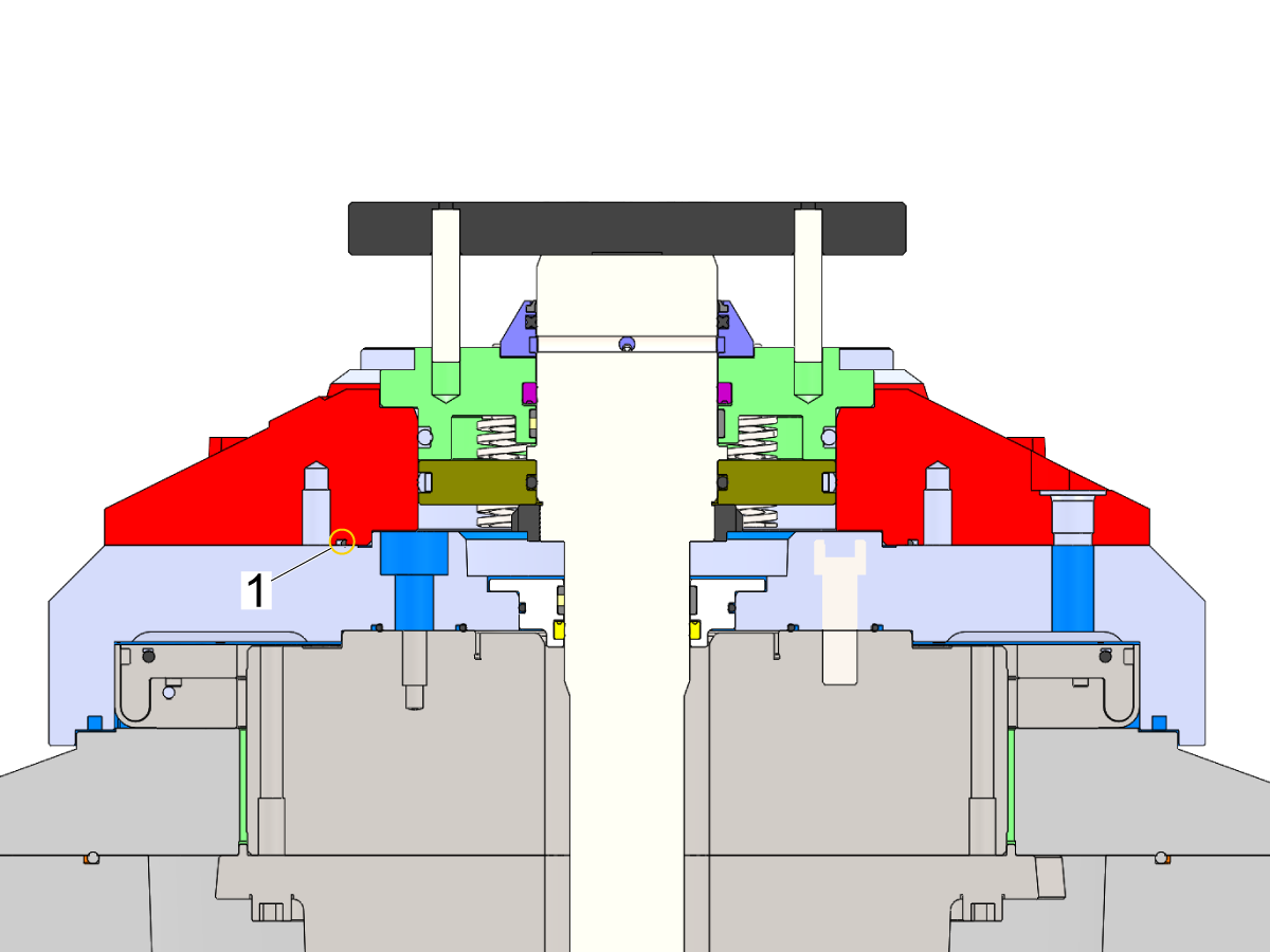
Apply a uniform layer of silicone grease to O-ring [1] to ensure proper sealing and ease of installation.

Seat the lubricated O-ring into the designated spotface [2] on the platter, ensuring it is properly fully seated.

5

Install 57-2975 O-ring [1] to the bottom side of the receiver, apply a thin layer of silicon grease to the O-ring.  

 NOTE: The kit is coated with anti-rust grease before shipping. If this grease is applied to the internal and external seals, please clean them and apply silicon grease to the seals.

 NOTE: Applying too much silicon grease may compromise sealing capabilities. 

6

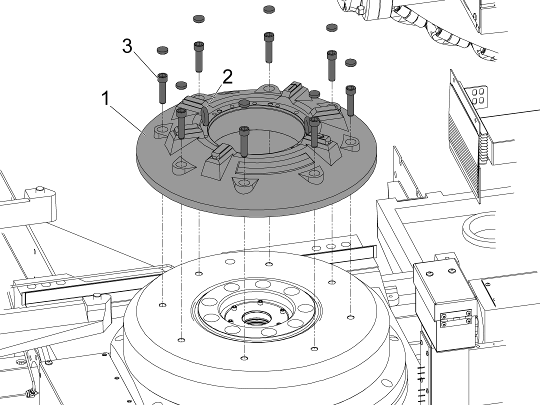
Install the receiver [1] to the platter assembly using the provided 5/16-18 eye bolts [2] in the kit. Place the eye bolts in the inner bolt pattern. Line up the brake bleed access hole on the platter with the access hole on the receiver.

Use the SHCS 1/2-13 X 2 [3] provided to bolt down the receiver. 

The receiver weighs approximately 150 lbs, use the proper lifting apparatus to safely lift this component. 

IMPORTANT: It is recommended to indicate and adjust the receiver axial and radial runout before installing the piston and other internal components, otherwise with all the internal components this will be much harder to do. 

7

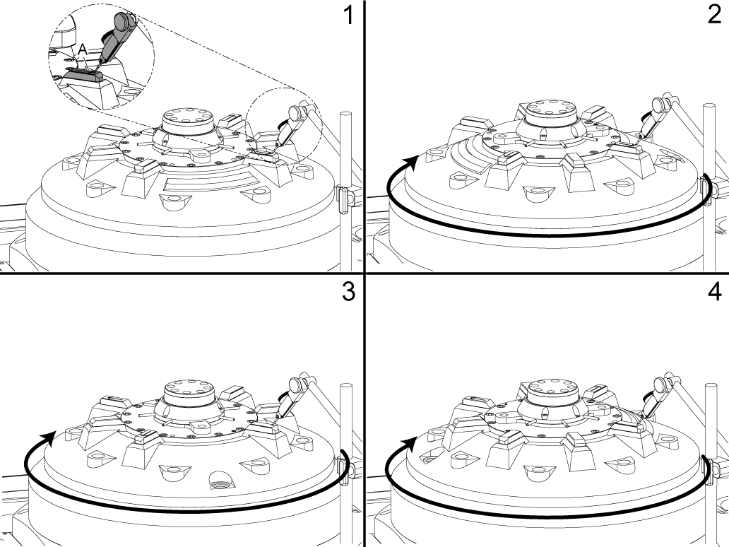
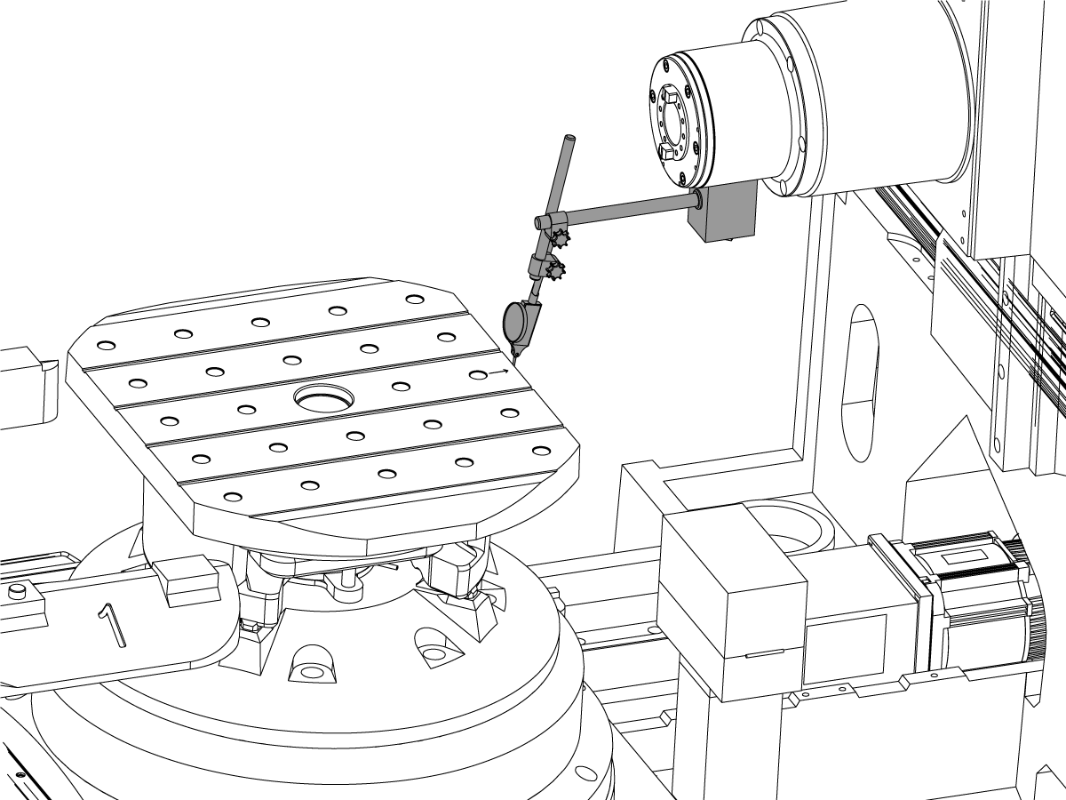
RECEIVER FACE RUNOUT:

With an indicator and mag base setup, locate the front right key and set the dial to zero. The front right key will have an arrow engraved on it [A].

Indicate the top face of the keys and measure face runout on the receiver rotate the receiver every 90 degrees this is NTE 0.0005 in (0.0127 mm) TIR. 

Once the runout has been adjusted torque the mounting bolts in star pattern referencing the HAAS TORQUE SPECIFICATION document. 

NOTE: The internal components (piston shaft, receiver cap and air blast manifold) are installed in the images, when they should not be. This step is to be used for reference.


8

RECEIVER RADIAL RUNOUT:

With an indicator and mag base setup, locate the front right key and set the dial to zero. The front right key will have an arrow engraved on it.

Indicate the side face of the keys and measure radial runout on the receiver, this is NTE 0.0005 in (0.0127 mm) TIR. 

NOTE: The internal components (piston shaft, receiver cap and air blast manifold) are installed in the images, when they should not be. This step is to be used for reference.

9

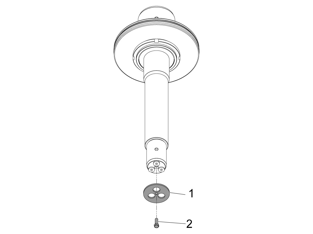
Remove the 1/4-20 bolt and retaining cap from the bottom shaft.

10

Install the external seal [1] on the piston and shaft assembly and add a layer of silicon grease.

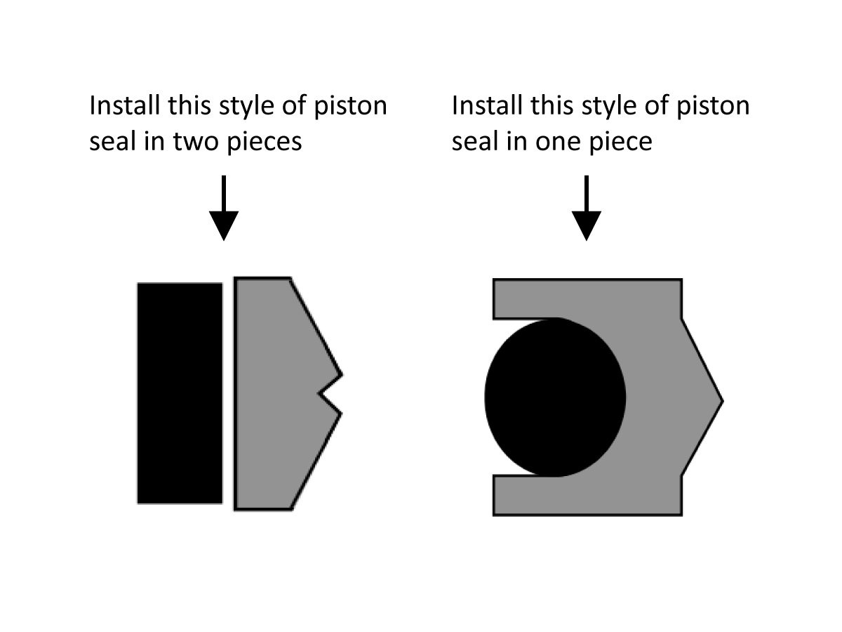
This piston will have a 2-piece seal the first piece of the seal, the energizer rests behind the outer part of the seal.

There are two possible piston seal combinations, please see the next step for further instructions on how to install. 

 NOTE: The kit is coated with anti-rust grease before shipping. If this grease is applied to the internal and external seals, please clean them and apply silicon grease to the seals.

11

Kits built after 7/2022 may have two possible piston seal styles. 

The seal combination on the left is what the kits were originally built with, the seal combination on the right is what the kits are currently being built with. 

If the kit comes with the left seal combination apply a thin layer of grease to the energizer and install first. Apply a thin layer of grease to the outer seal and install. 

If the kit comes with the right seal combination apply a thin layer of grease to the energizer and apply a thin layer of grease to the outer seal and install it in one piece. 

 NOTE: Applying too much silicon grease may compromise sealing capabilities. 

12

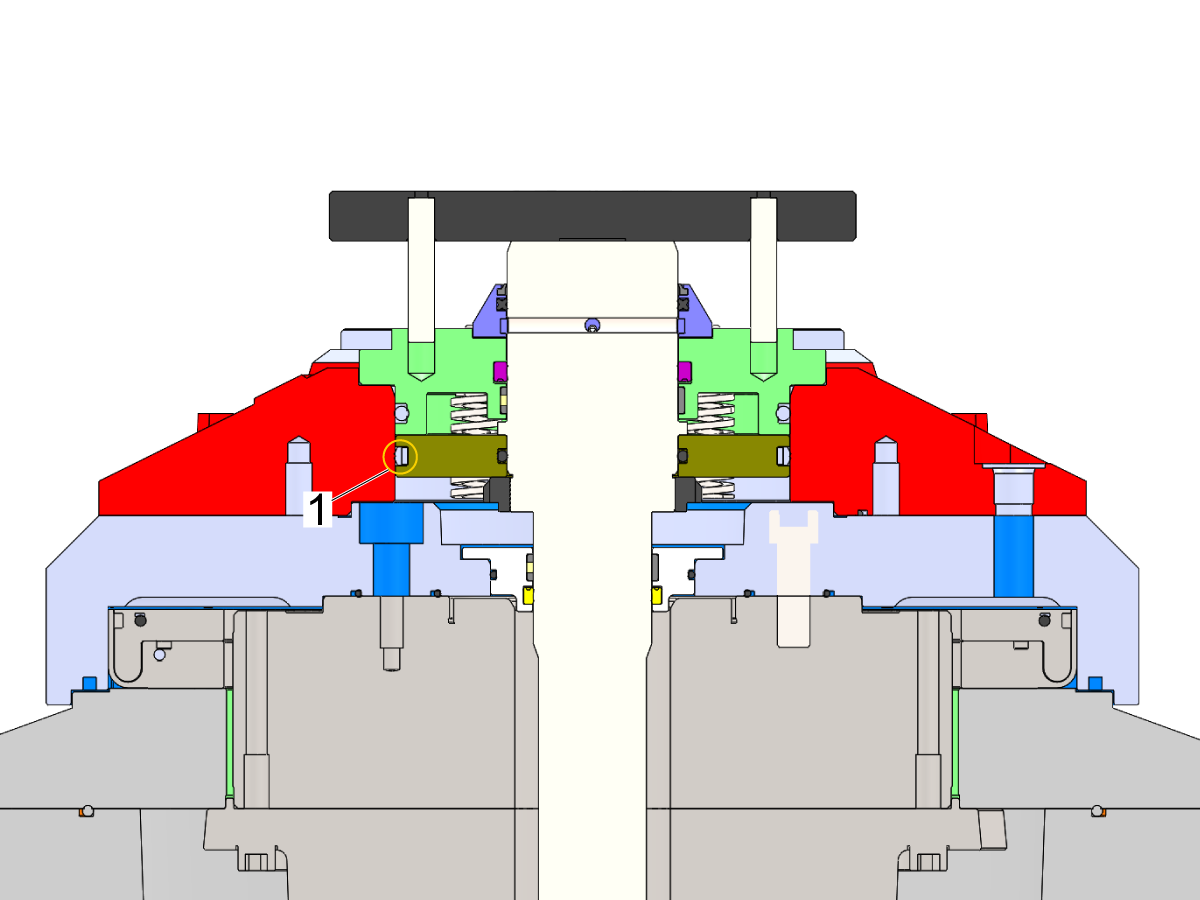
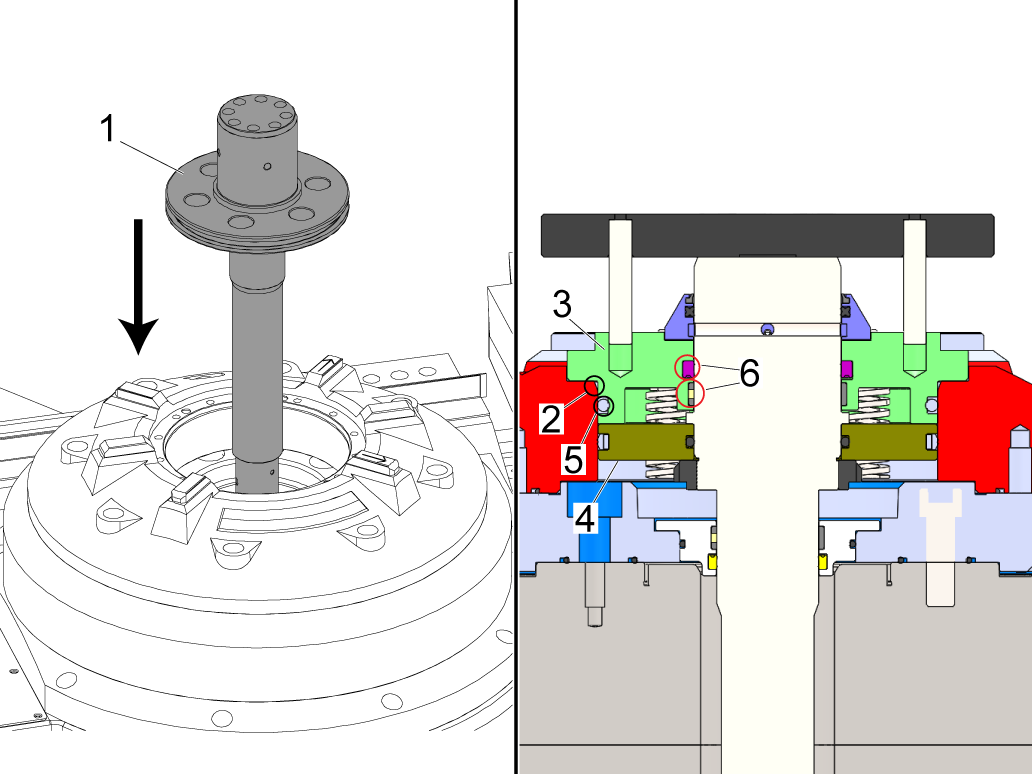
Install the piston and shaft assembly [1] using the 1/2-13 eye bolts. 

The piston will need to get past the chamfer [2] on the receiver to do so we recommend using the receiver cap [3] to press the piston past the chamfer. 

Install 57-2155 the external O-ring [5] of the receiver cap [3] apply a thin layer of silicon grease to both the external and internal seals.

Make sure both external and internal seals [5] and [6] still have enough silicon grease for permanent installation. 

 NOTE: The kit is coated with anti-rust grease before shipping. If this grease is applied to the internal and external seals, please clean them and apply silicon grease to the seals.

 NOTE: Applying too much silicon grease may compromise sealing capabilities

 NOTE: Applying a coat of grease to the inner bore of the receiver will help with installation. 

13

 NOTE: The springs from the old receiver assembly will be reused on this assembly. Using the springs to install the piston shaft assembly will also allow the piston to reach its desired position against the top of the platter. 

Install the springs [1] in the grooves on the piston and install the cap [2] to the receiver casting using the 5-16-18 threaded rods provided in the kit, place them in 3 equally spaced bolt holes. Tighten the nuts in 1/2 turn increments to get the piston past the chamfer.

 IMPORTANT: Make sure to evenly lower the cap if it is not the piston can wedge against the receiver and cause metal to metal contact and damage the assembly. 

Use the provided nuts/studs to evenly drive down the cylinder cap enough to engage the SHCS 5/16-18 X 7/8 [3] and allow the piston to move past the chamfer. Tighten the bolts down until they are snug.

Verify the orientation of the receiver cap matches the image with the piston cap boss parallel to the keys with arrows. Torque the mounting hardware to the specified value.

HAAS TORQUE SPECIFICATION

14

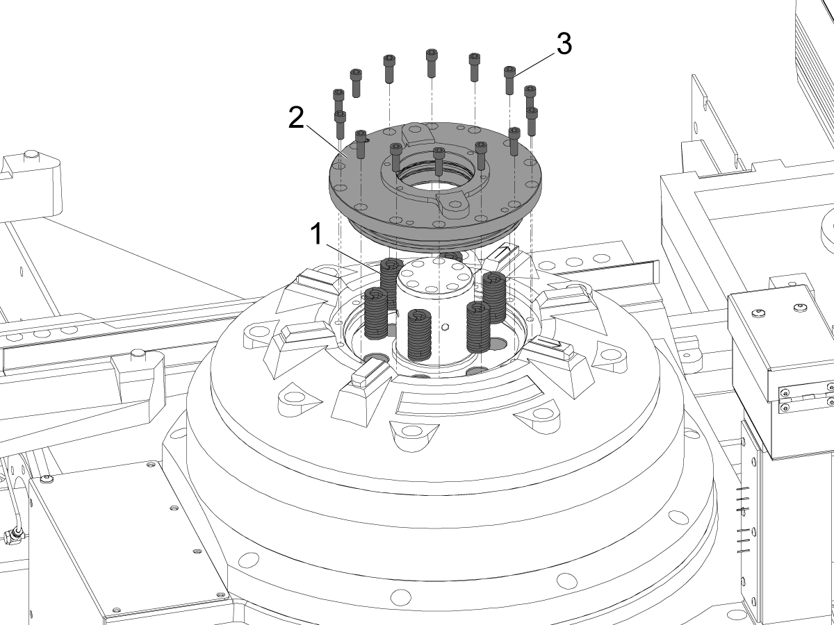
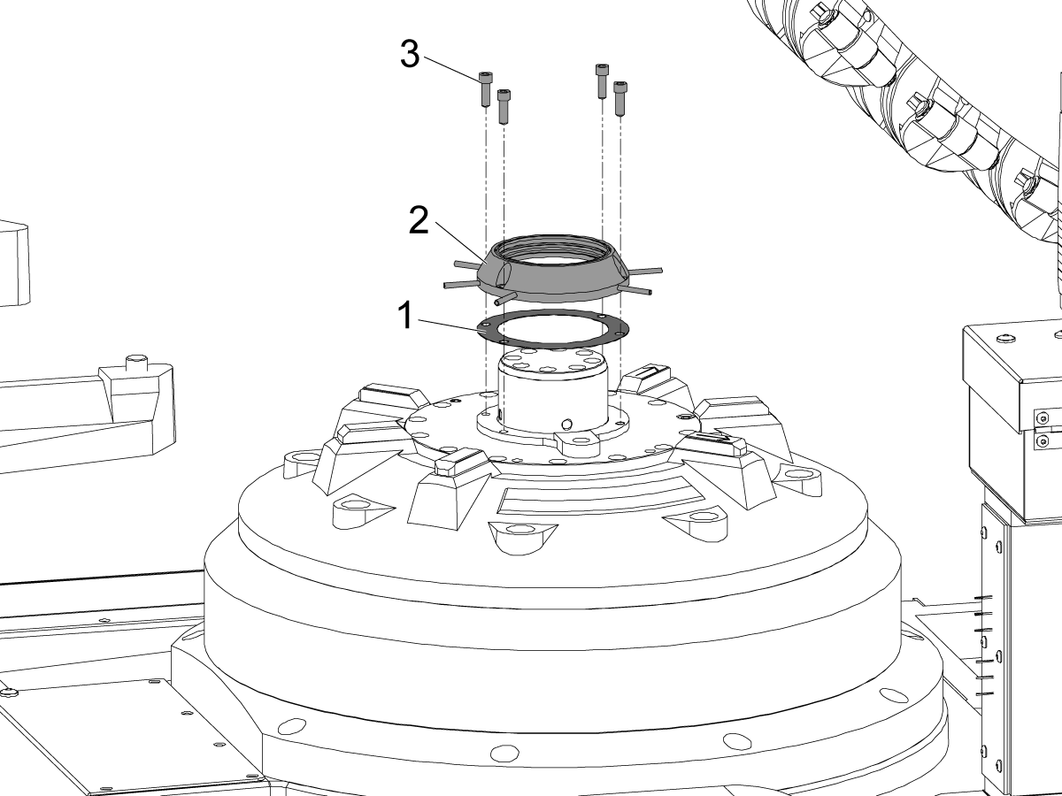
Grease the internal seals using silicon grease in the air blast manifold.

Place the gasket [1] between the receiver cap and the air blast manifold assembly [2] and install using the provided hardware [3]. 

 NOTE: The kit is coated with anti-rust grease before shipping. If this grease is applied to the internal and external seals, please clean them and apply silicon grease to the seals.

15

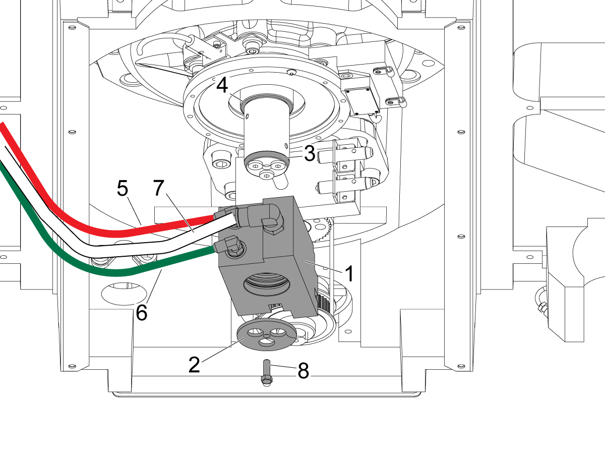
Install the hydraulic manifold [1] on the under the gearbox and reconnect the lines. 

Grease the dowel pins using tacky grease. 

NOTE: It is recommended to use the retaining cap [2] to raise the manifold into position. Use a longer screw(s) or an appropriately sized 1/4-20 threaded rod with a 1/4-20 nut in place of the mounting bolt [8] to fully seat the hydraulic manifold

Using the longer screws or threaded rod with the retaining cap pull the manifold in place until all 4 internal seals have passed over the first chamfer [3] and bottom out at the upper lip [4].

Once the manifold is fully installed remove the longer bolt/threaded rod and install the original 1/4-20 mounting hardware.

NOTE: The line denoted in RED [5] is unclamp, and the line denoted in GREEN [6] is clamp. The air line goes in the clear port [7]. Use the zip ties previously added to aid reinstallation.

Reinstall the sensor block in the correct orientation. The sensors may need to be readjusted if clamp/unclamp alarms appear.

IMPORTANT: Verify all hydraulic hoses keep clear from rotary encoder during clamp/unclamp positions.


16

Verify that the hydraulic pressure is zero on the gauges page before installing all the hoses back to the manifold block.

Install the hydraulic hoses to the clamp block and to the appropriate ports on the hydraulic manifold. Use the zip ties previously added to aid reinstallation.

With all the hydraulic hoses reinstalled the HPU can be repressurized, but it will be done later in the procedure.

In the meanwhile, download and apply the patches designated for this kit from HBC, if there is any difficulty applying the patch contact Haas Service for further assistance. 

RECEIVER VERIFICATIONS:

Record the values of the measurements in this section and submit to Haas Service to attach to the machine history.

1

ROTARY FLATNESS:

With an indicator and mag base setup, locate the front right key and set the dial to zero. The front right key will have an arrow engraved on it.

Do not rotate the rotary during this check. Indicate the top surface on the four outside bosses, this is NTE 0.0003 in (0.00762 mm). Shim the rotary base if necessary.

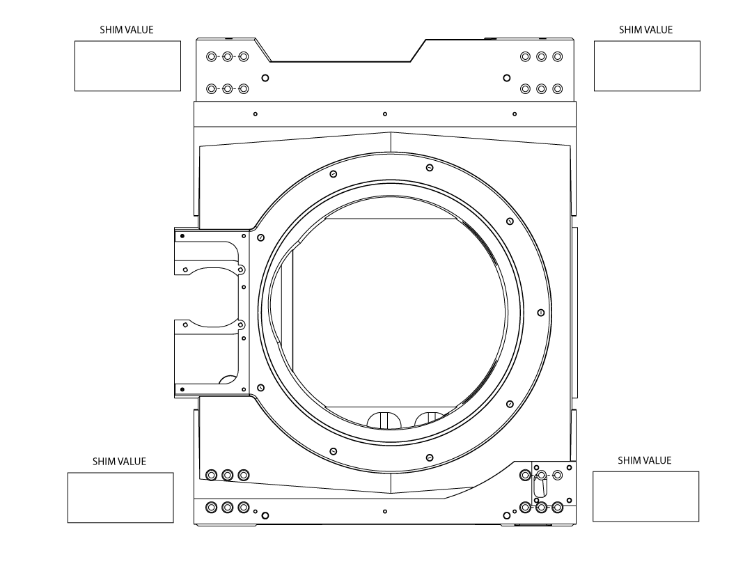
2

Shims to correct the receiver flatness will be placed underneath the trucks. 

NOTE: Shimming under the trucks should not be necessary. Please verify that the receiver is properly installed (all mounting bolts are torqued, receiver cap is properly installed, etc.) before attempting to shim under the trucks.

There will be thick shims (0.2170 in or 5.5118 mm) already placed from the factory. Please record the value of shims placed under the trucks after installing the new receiver and submit this to Haas Service for records. 

3

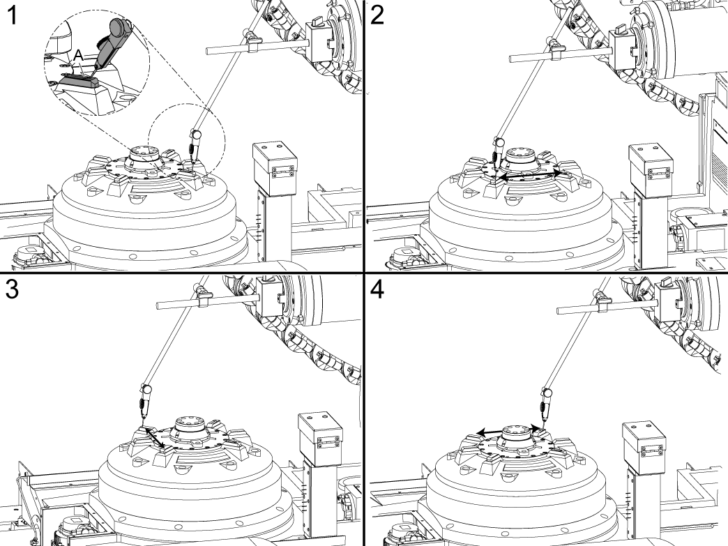
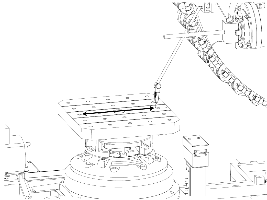
RECEIVER X-AXIS PARALLELISM:

Locate the front edge of the key on the right, set the dial to zero.

Press [POSITION] and navigate to the operators tab and set the Y value to zero.  

Jog X to record value on the key directly across from it, to avoid the key in between jog the Y axis up and over that key and back to the Y-Axis zero location set on the operators tab.  

This is NTE 0.0003 in (0.00762 mm). Adjust the B axis until the indicator reading is within specification.  

Press [DIAGNOSTIC] and navigate to the Parameters Tab find parameter 6.078 [213:] B-AXIS TOOL CHANGE OFFSET and while on the parameter page in service mode, press B + F2 to set the TC Offset.

4

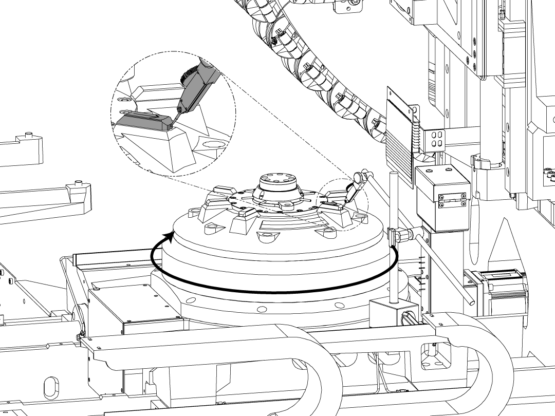
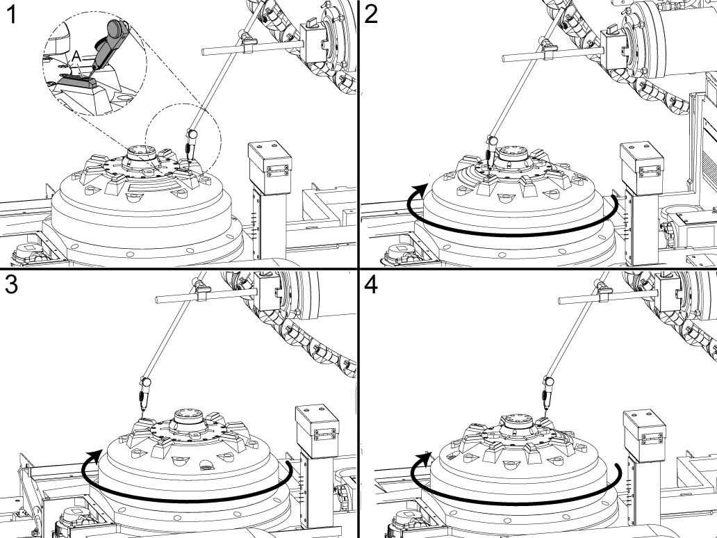
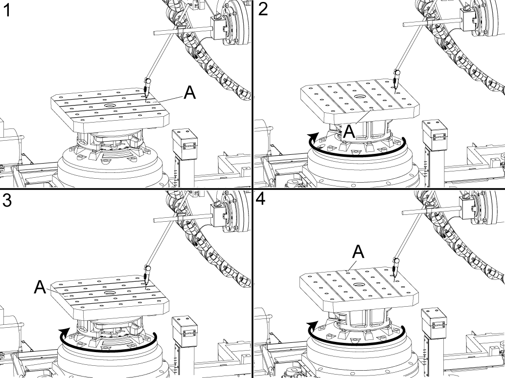
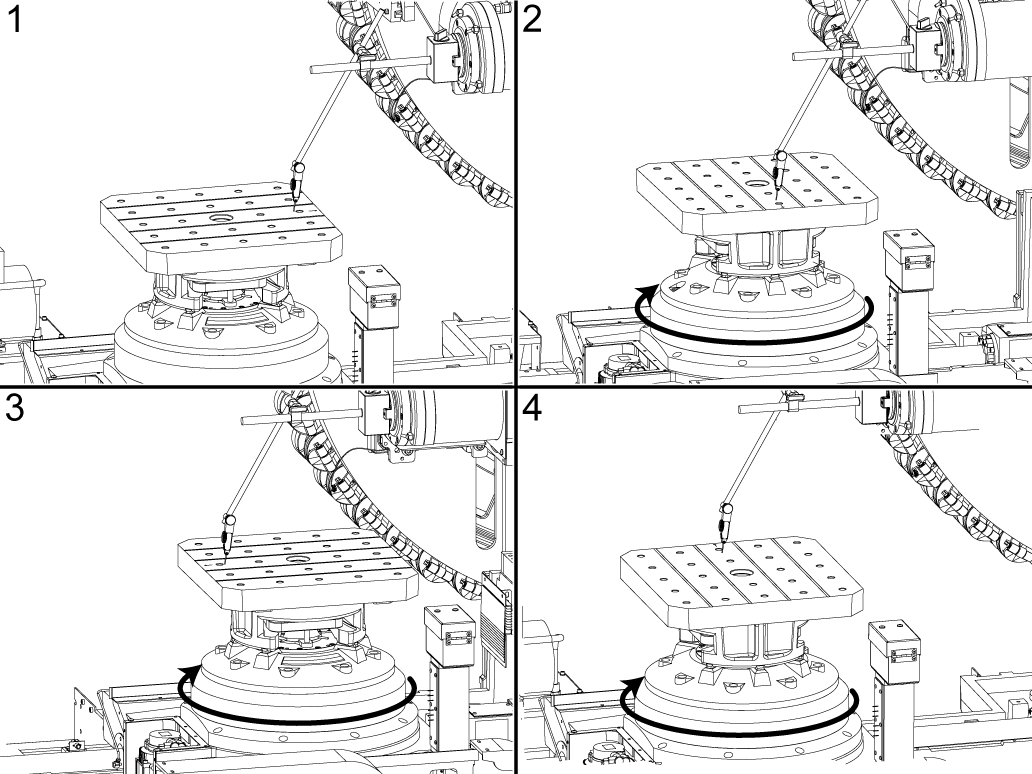
AXIS OF ROTATION:

With an indicator and mag base setup, locate the front right key and set the dial to zero. The front right key will have an arrow engraved on it [A].

Rotate the rotary every 90 degrees and move your X and Z axis so that the indicator is marking the same point and record this value.

In this example the indicator is following the front right key with the arrow engraved. This value is NTE 0.0005 in (0.0127 mm)

5

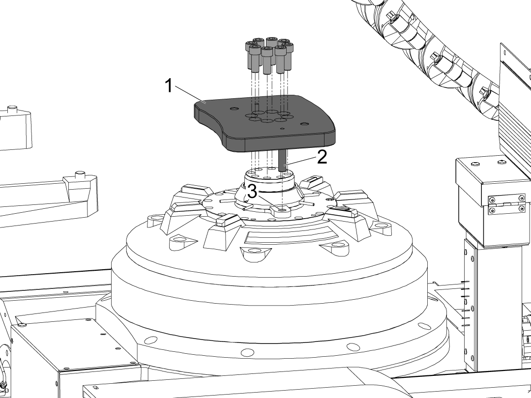
Install the pallet clamp plate [1], if the dowel pins [2] do not line up with the holes [3] the clamp shaft will need to rotate into position. 

To rotate the shaft into position, use the mounting bolts without the clamp plate installed, a screw driver can be wedged between and used to turn the shaft into the correct position. 

NOTE: Apply tacky grease to the dowel pins [2].

Repressurize the HPU

1

Set parameter 40.011 HPU 1 TYPE [1] from DISABLED [2] to its original state.

2

Repressurize the HPU using the HPU DEPRESSURE page.

Press [DIAGNOSTIC] then navigate to the MAINTENANCE tab [1] then navigate to the HPU DEPRESSURE tab [2]. Press [F4] to restart the HPU [3].


3

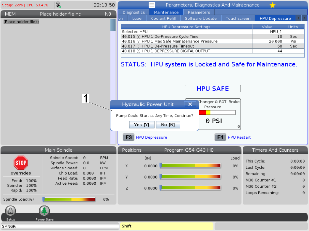
A prompt will show up that the pump could start any time.

Press YES [Y] and the pump will restart.

4

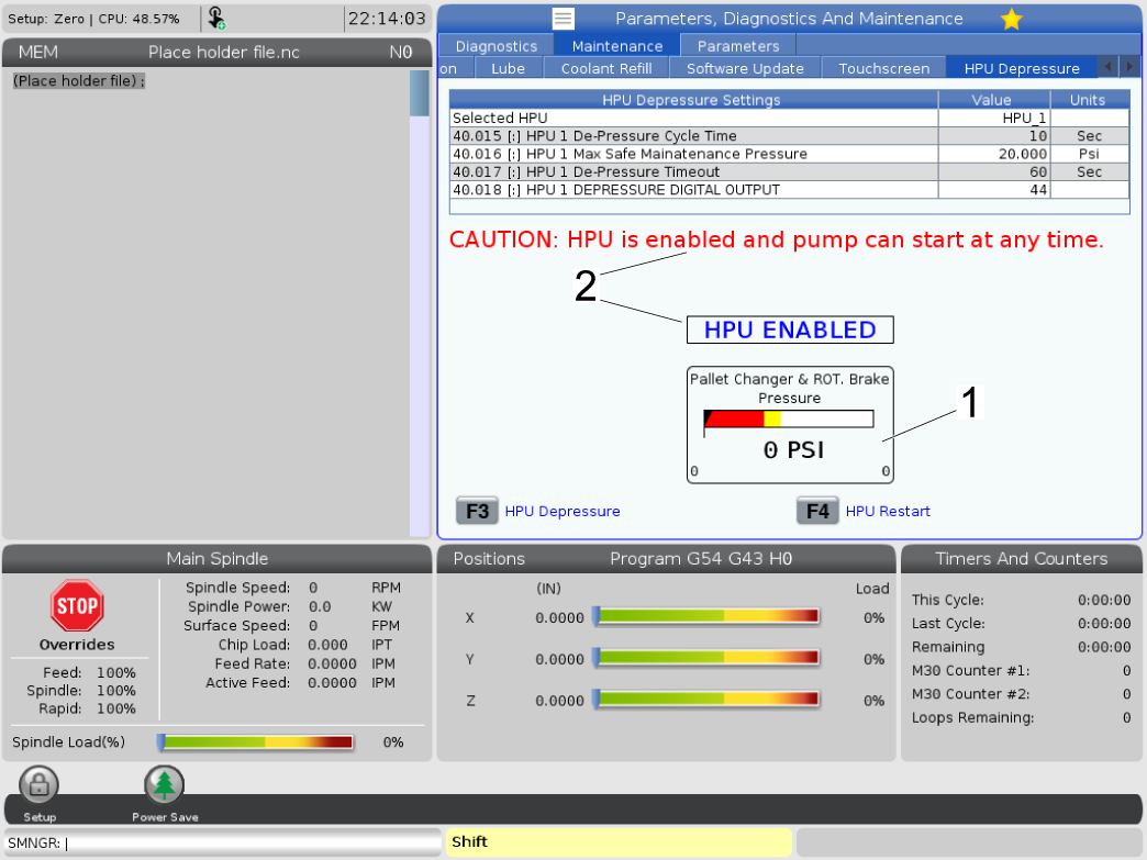
The HPU pressure gauge will rise to 550 PSI [1] and the page will display cautionary text that the pump is enabled [2].

NOTE: This image uses a simulator page for reference, the gauge SHOULD NOT read 0 PSI after restarting the pump. 

Verify no leaks are present after restarting the pump. 

5

Raise the Hydraulic Power Unit (HPU) pressure to 600 PSI to match the clamp force of the previous design.

Navigate to the diagnostics and locate the HPU pressure gauge.

Loosen the jam nut [1].

Tighten the set screw [2] gradually while monitoring the pressure gauge.

Continue tightening until the gauge reads 600 PSI.

Once the desired pressure is reached, re-tighten the jam nut [1] to lock the set screw in place.


PALLET VERIFICATIONS:

The following steps are to ensure that the pallet is within specification. If any of measurements on the first pallet is not within specification, please check the remaining pallets.

If the remaining pallets are not within specification, verify the receiver measurements are correct before determining the pallet's do not meet specification.

If a pallet is not within specification, please contact Haas Service for further assistance and evaluation. 

Once the pallet verifications are complete also complete an inspection report by following the link below. Be sure to download the correct inspection report for the correct machine. EA0419 for EC-400/500 and EA0429 for EC-500/50 and EC-630.

Inspection Report List

Record the values of the measurements in this section and submit the inspection report and pallet verifications to Haas Service to attach to the machine history.

1

Zero return the B Axis, mount a mag base with an indicator on the spindle. indicate the side face of the pallet in the X direction. This value is NTE 0.002 in ( 0.0508 mm).

NOTE: If this measurement does not meet specification on all the pallets correct the B-axis Tool Change Offset.

Handle jog the B axis until the indicator reading in within specification and press [DIAGNOSTIC] and navigate to the Parameters Tab find parameter 6.078 [213:] B-AXIS TOOL CHANGE OFFSET and while on the parameter page in service mode, press B + F2 to set the TC Offset.

Command a pallet change to verify that the B and Z axis TC Offsets are set correctly.

2

PALLET FACE RUNOUT:

With an indicator and mag base setup, place the indicator center of the side closest to the spindle and set the dial to zero. The pallet will have an arrow pointing towards the spindle, for reference place the indicator in front of the hole where the arrow is [A].

Without moving the indicator, rotate the pallet every 90 degrees and record the value on the indicator. This value is NTE 0.001 in (0.0254 mm).

3

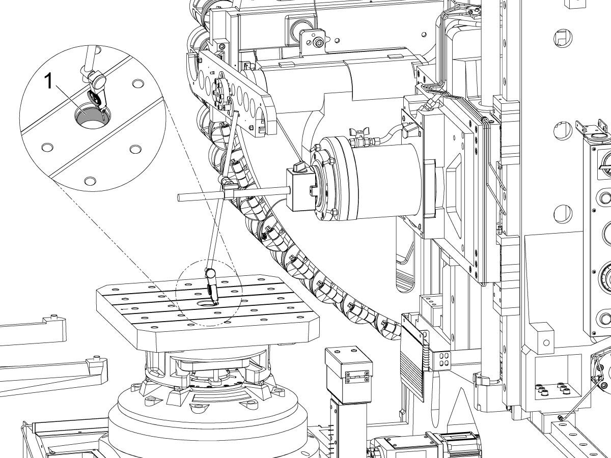
PALLET CENTER BORE:

Place the tip of the indicator in the center of the bore on the pallet, jog in the Z-direction to the bottom half of the bore and jog to one side of the bore and set the dial to zero [1].

Rotate the pallet 360 degrees and record the value, this is NTE 0.003 in (0.0762 mm) TIR.

4

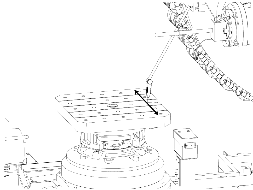
PALLET FLATNESS IN X DIRECTION:

Pick up a zero point on the top front right edge of the pallet, sweep the pallet in the X direction and record the value. This value is NTE 0.0005 in/10 in (0.0127 mm/ 254 mm)

5

PALLET FLATNESS IN Z DIRECTION:

Pick up a zero point on the top front right edge of the pallet, sweep the pallet in the Z direction and record the value. This value is NTE 0.0005 in/10 in (0.0127 mm/ 254 mm)

6

PALLET AXIS OF ROTATION:

With an indicator and mag base setup, place the indicator center of the side closest to the spindle and set the dial to zero. The pallet will have an arrow pointing towards the spindle, for reference place the indicator in front of the hole where the arrow is [A].

Rotate the rotary every 90 degrees and move your X and Z axis so that the indicator is marking the same point and record this value.

In this example the indicator is following the front right key with the arrow engraved. This value is NTE 0.001 in (0.0254 mm)

HSG - 9/15/2022

Recently Viewed Items

You Have No Recently Viewed Items Yet

Feedback
Haas Logo

Haas Delivered Price

This price includes shipping cost, export and import duties, insurance, and any other expenses incurred during shipping to a location in France agreed with you as a buyer. No other mandatory costs can be added to the delivery of a Haas CNC Product.

KEEP UP WITH THE LATEST HAAS TIPS AND TECHNOLOGY...

Sign up now!   

HAAS TOOLING ACCEPTS THE FOLLOWING:

  • Service & Support
  • Owners
  • Request Service
  • Operator Manuals
  • Haas Parts
  • Rotary Repair Request
  • Pre-Install Guides
  • Shopping Tools
  • Build & Price a New Haas
  • Available Inventory
  • The Haas Price List
  • CNCA Financing
  • About Haas
  • Accessibility Statement
  • DNSH Statement
  • Export Compliance
  • Careers
  • Certifications & Safety
  • Contact Us
  • History
  • Terms & Conditions
  • Haas Tooling Terms & Conditions
  • Privacy
  • Warranty
  • Haas Community
  • Haas Certification Program
  • Haas Motorsports
  • Gene Haas Foundation
  • Haas Technical Education Community
  • Events
  • Join the Conversation
  • Facebook
  • X
  • Flickr
  • YouTube
  • LinkedIn
  • Instagram
  • TikTok
© 2026 Haas Automation, Inc – CNC Machine Tools
This site is protected by reCAPTCHA and the Google Privacy Policy and Terms of Service apply.

2800 Sturgis Rd., Oxnard, CA 93030
Toll Free: (888) 817-4446 / Fax: 805-278-8554