-
機械
クイックリンク 特殊シリーズ 特殊シリーズショッピングツール
- オプション
-
Why Haas
Haasの特徴を見る
-
サービス
Haasサービスへようこそ
- ビデオ
-
MyHaas - すべてをひとつの場所で

AD0521
This procedure outlines how to install the Chip Lift.
Important: If you do not have the hinged door installed over the I/O PCB, you must also install P/N: 93-1000573.
Document Applies to these Parts:
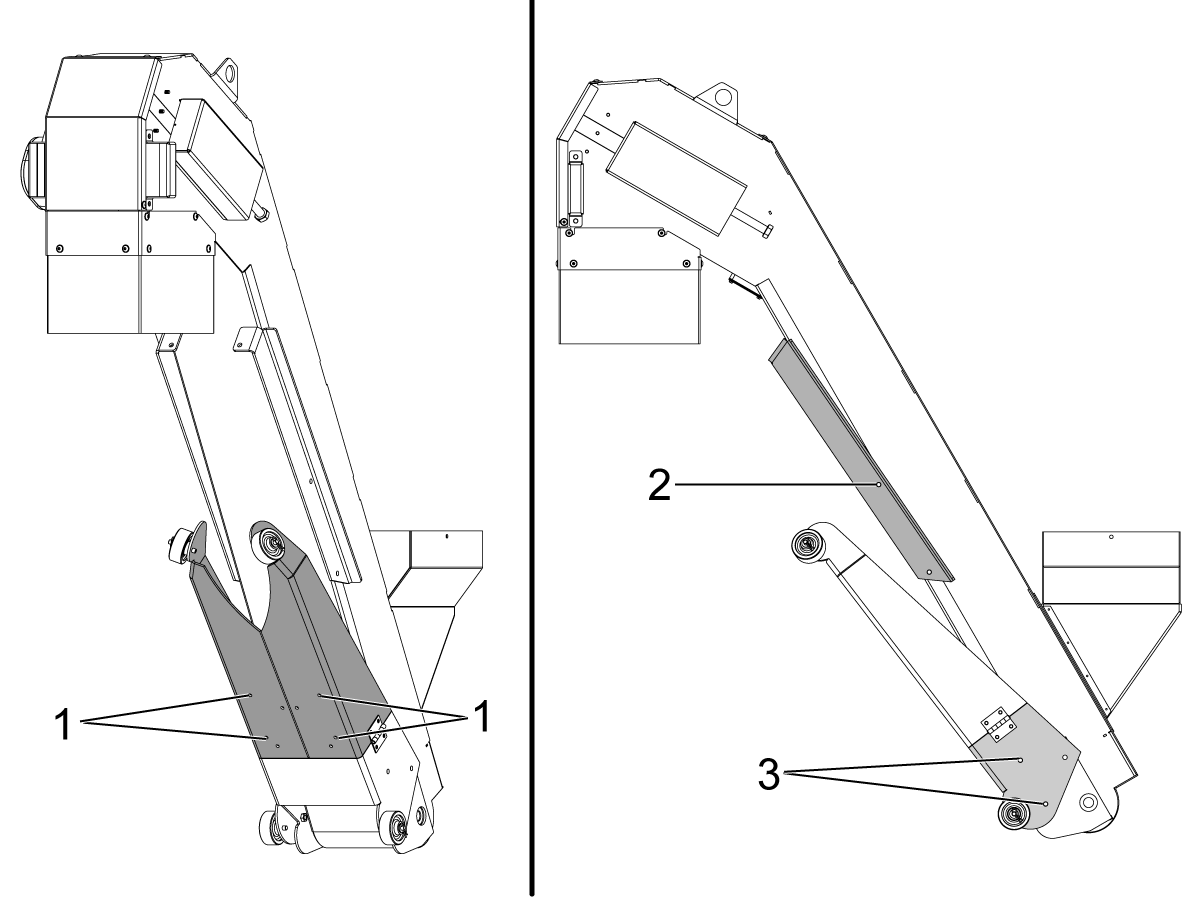
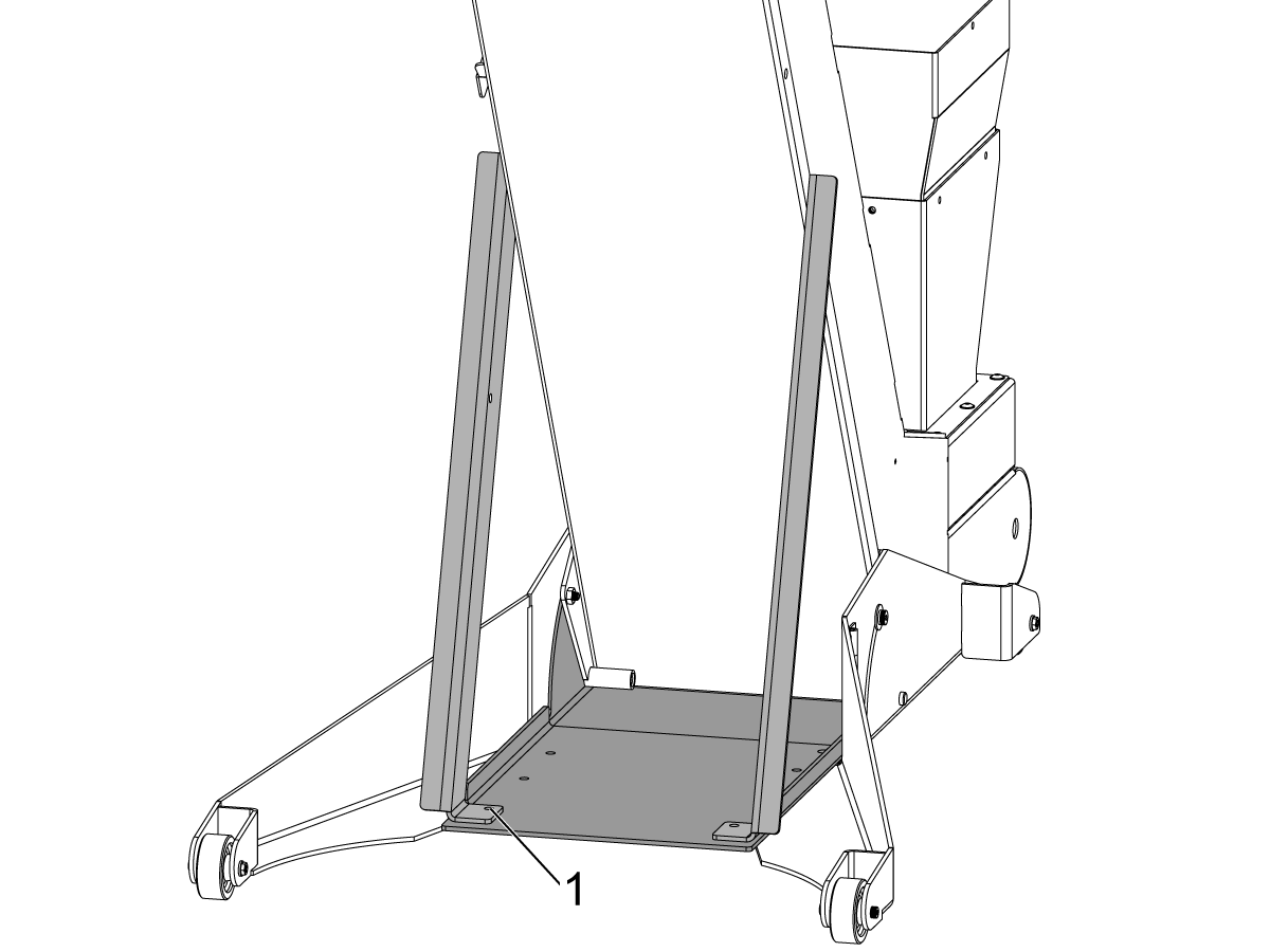
Unbolt the hardware [1], open the legs, and reinstall the hardware [1].
Remove the bolts [3], unfold, and reinstall the hardware [3].
Removes bolts [2].
Note: The front safety cover is shown for illustration purposes, but will be installed later in step 5.
Bolt down the opened legs [1].
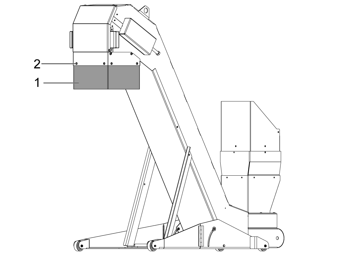
Attach the safety cover [1] at the correct height using the provided hardware [2].
Note: The Chip Lift can be installed in three different orientations, attach the safety cover to fit the direction desired.
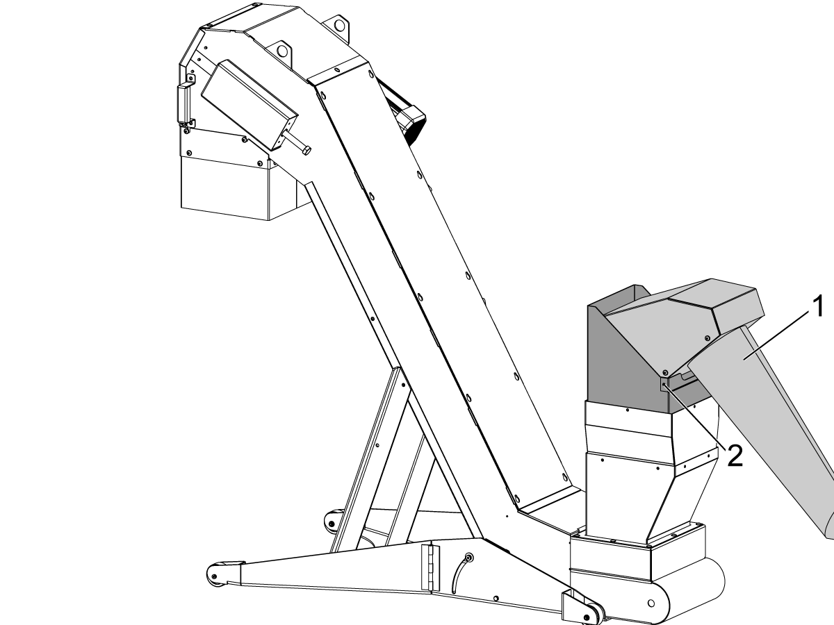
Attach the front safety cover [1] using the provided hardware [2].
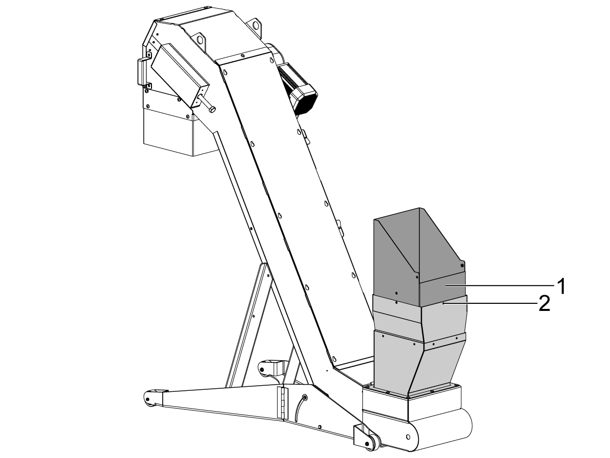
Roll the Chip Lift [1] up to the Chip Chute [2].
Bolt the chip chute [2] to the safety cover [1] using the provided hardware [3].
For VF machines
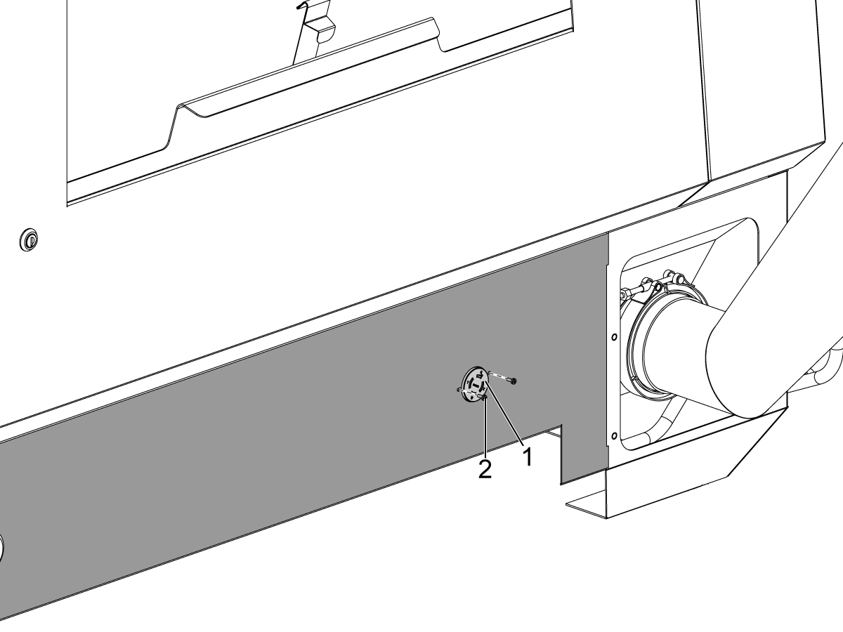
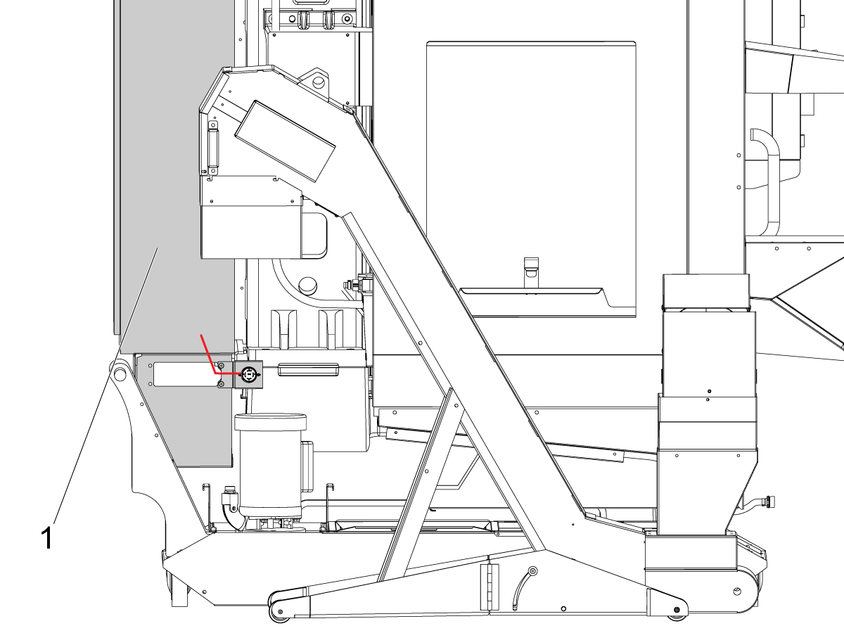
Fasten the motor power cord [1] that comes from the elctrical cabinet using a clamp in the back.
Secure the motor power cord and clamp to the machine skirt as shown using the provided hardware [2].
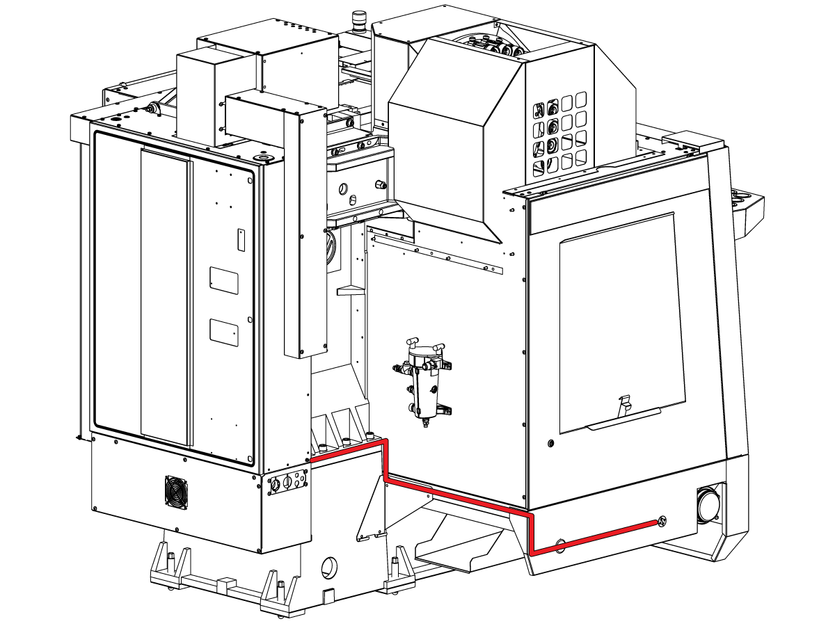
For VF machines
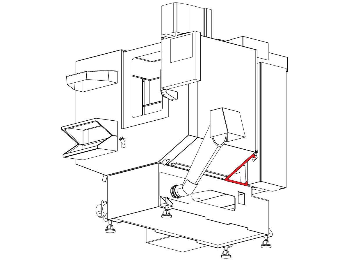
Route the CHIP CONVYR EXT CBL to the control cabinet as shown.
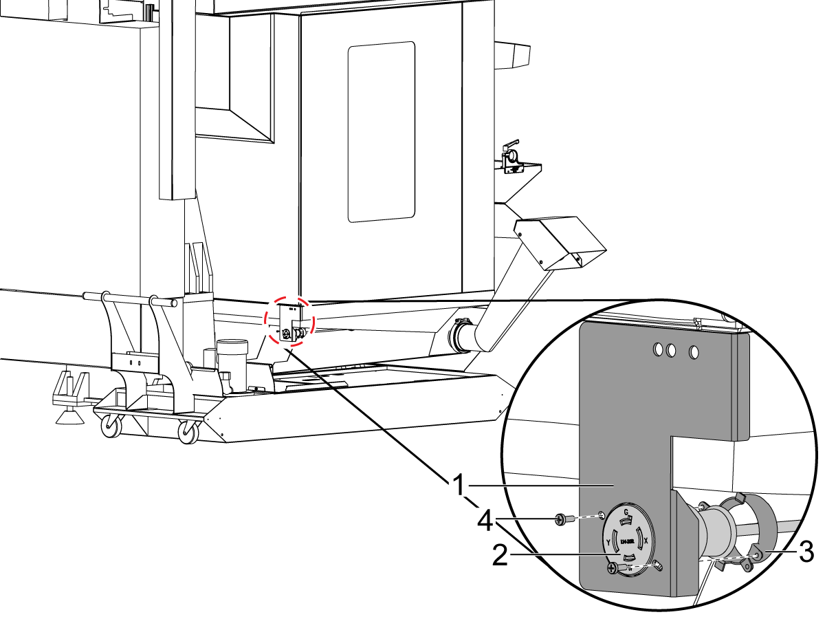
For DT/DM machines
Attach the provided bracket [1] to the machine as shown.
Fasten the motor power cord [2] that comes from the elctrical cabinet to the bracket [1] using a clamp in the back [3] and the provided hardware [4].
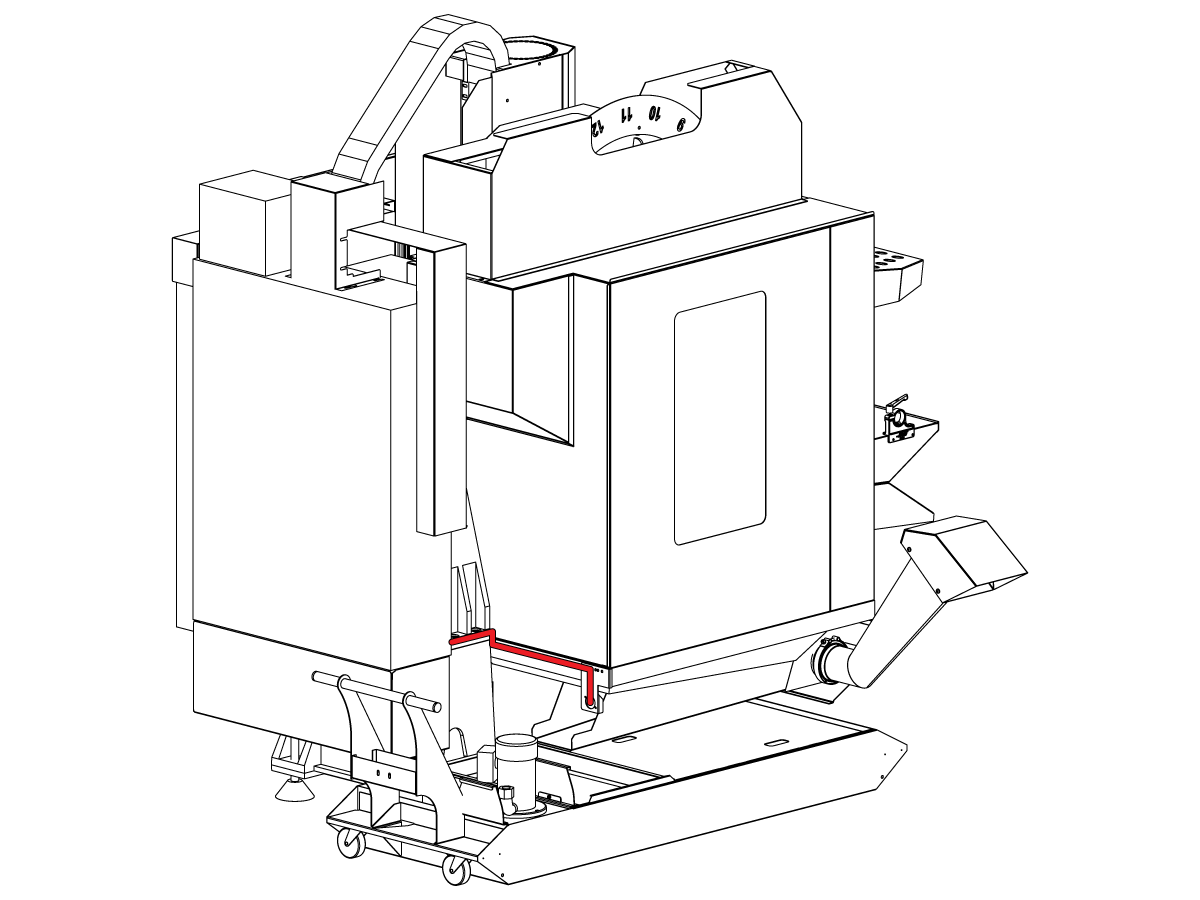
For DT/DM machines
Route the CHIP CONVYR EXT CBL to the control cabinet as shown.
For MM machines
Attach the provided bracket [1] to the machine as shown.
Fasten the motor power cord [2] that comes from the elctrical cabinet to the bracket [1] using a clamp in the back [3] and the provided hardware [4].
For MM machines
Route the CHIP CONVYR EXT CBL to the control cabinet as shown.
Push [POWER OFF].
Set the main circuit breaker to the OFF position.
Lock the main circuit breaker. Use an approved lock with an approved safety tag.
Caution: When you handle a PCB, you must wear an Electrostatic Discharge (ESD) strap.
This step shows you how to install the hinge door on the I/O PCB. Skip this step If you machine already has a hinge door installed.
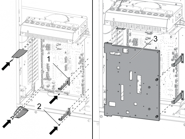
Remove the I/O PCB cover and standoffs from the control cabinet.
Install the (4) screws to attach the I/O PCB.
Install the (4) I/O PCB brackets [1].
Install the (8) screws [2] to support the brackets.
Install the Hinge Door [3] for the I/O PCB.
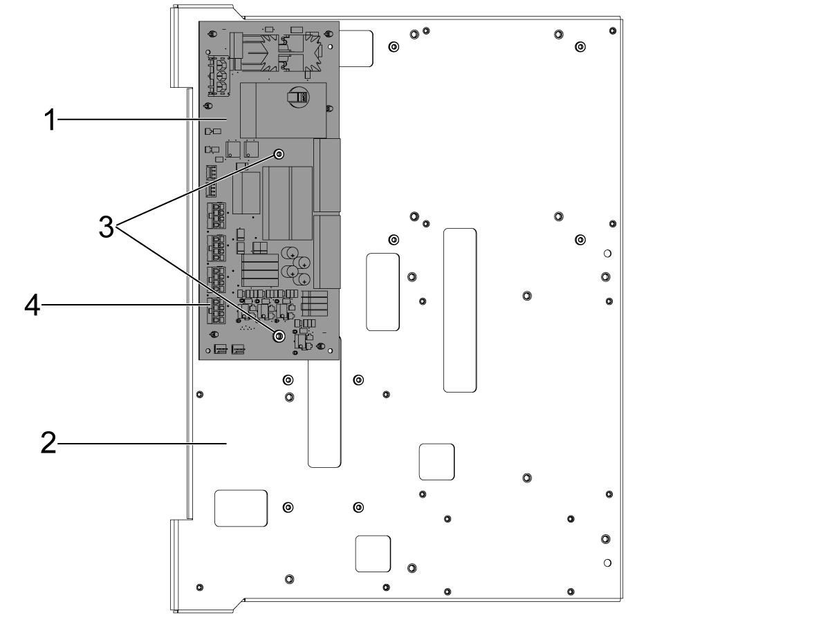
Connect the CHIP QD PCB [1] to the hinge door [2] using the provided hardware [3].
Connect the cable from the motor to the CHIP QD PCB [4].
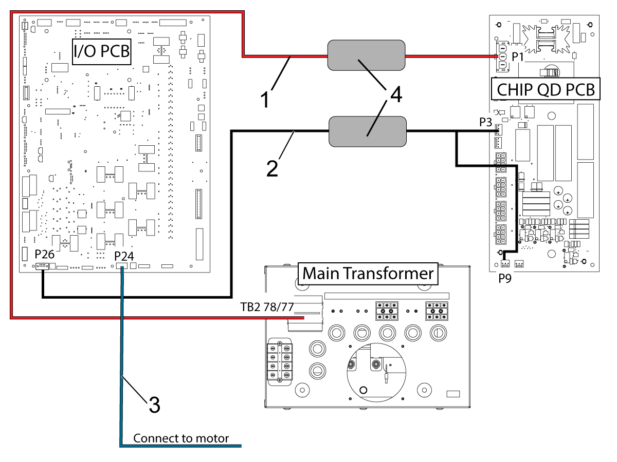
Connect cable 33-0188 [1] from [P1] on the CHIP QD PCB to [TB2 78/77] on the Main Transformer.
Connect cable 33-1170 [2] from [P3] and [P9] on the CHIP QD PCB to [P26] on the I/O PCB. Then make sure the circuit breaker on the CHIP QD PCB is in the [ON] position.
Connect the CHIP CONVYR EXT CBL [3] to P24 on the I/O PCB.
Note: When a machine has a Multi-Auger system, move the multi-auger connection from P24 on the I/O Board to P4 on the CHIP QD PCB.
Install the ferrite filters [4].
Press [POWER ON] to turn on the machine.
Zero return all axes.
Press [CHIP FWD] to start the chip lift to make sure everything runs smoothly and no alarms go off.