My Haas Welcome,
!
Haas Tooling MyHaas/HaasConnect Sign In Register Haas Tooling MyHaas/HaasConnect Sign Out Welcome, My Machines Latest Activity My Quotes My Account My Users Sign Out
Find Your Distributor
  1. Select Language
    1. English
    2. Deutsch
    3. Español - ES
    4. Español - MX
    5. Français
    6. Italiano
    7. Português
    8. Český
    9. Dansk
    10. Nederlands
    11. Magyar
    12. Polski
    13. Svenska
    14. Türkçe
    15. 中文
    16. Suomi
    17. Norsk
    18. الإنجليزية
    19. български
    20. Hrvatski
    21. Ελληνικά
    22. Română
    23. Slovenský
    24. Slovenščina
    25. 한국어
    26. 日本語
    27. Українська
  • machines Main Menu
    • Vertical Mills
      Vertical Mills
      Vertical Mills View All
      • Vertical Mills
      • VF Series
      • Universal Machines
      • VR Series
      • VP-5 Prismatic
      • Pallet-Changing VMCs
      • Mini Mills
      • Mold Machines
      • High-Speed Drill Centers
      • Drill/Tap/ Mill Series
      • Toolroom Mills
      • Pocket Mill
      • Compact Mills
      • Gantry Series
      • SR Sheet Routers
      • Extra-Large VMC
      • Double-Column Mills
      • 3+2 Positioning Machines
    • Multi-Axis Solutions
      Multi-Axis Solutions
      Multi-Axis Solutions View All
      • Multi-Axis Solutions
      • Y-Axis Lathes
      • 5-Axis Mills
    • Lathes
      Lathes
      Lathes View All
      • Lathes
      • ST Series
      • Dual-Spindle
      • Box Way Series
      • Toolroom Lathes
      • Chucker Lathe
      • Pocket Lathe
      • Haas Bar Feeders
    • Horizontal Mills
      Horizontal Mills
      Horizontal Mills View All
      • Horizontal Mills
      • 50-Taper
      • 40-Taper
    • Rotaries & Indexers
      Rotaries & Indexers
      Rotaries & Indexers View All
      • Rotaries & Indexers
      • Rotary Tables
      • Indexers
      • 5-Axis Rotaries
      • Extra-Large Rotaries
    • Special Series
      Special Series
      Special Series View All
      • Special Series
      • EU_Series_Redirect
    • Automation Systems
      Automation Systems
      Automation Systems View All
      • Automation Systems
      • Mill Automation
      • Lathe Automation
      • Automatic Parts Loaders
      • Automation Models
    • Desktop Machines
      Desktop Machines
      Desktop Machines View All
      • Desktop Machines
      • Desktop Mill
      • Desktop Lathe
      • Control Simulator, Standard
      • Control Simulator, Premium
    • Shop Equipment
      Shop Equipment
      Shop Equipment View All
      • Shop Equipment
      • Knee Mill
      • Haas Manual Lathes
      • Haas Saws
    • Fabrication Machines
      Fabrication Machines
      Fabrication Machines View All
      • Fabrication Machines
      • Laser Cutting Machines
      • CNC Press Brakes
    • QUICK LINKS Special Series  Special Series 
      EU SERIES EU SERIES BUILD & PRICE | PRICE LIST BUILD & PRICE | PRICE LIST In-Stock Machines In-Stock Machines WHAT’S NEW WHAT’S NEW YOUR FIRST CNC YOUR FIRST CNC
      SHOPPING TOOLS
      • Build & Price a Haas
      • Price List
      • Available Inventory
      • CNCA Financing
      WANT TO TALK TO SOMEONE?

      A Haas Factory Outlet (HFO) can answer your questions, and walk you through your best options.

      CONTACT YOUR DISTRIBUTOR >
  • Options Main Menu
    • The Haas Control Value Option Packages
      Value Option Packages
      Value Option Packages View All
      • Value Option Packages
    • Product Image Spindles
      Spindles
      Spindles View All
      • Spindles
    • Product Image Tool Changers
      Tool Changers
      Tool Changers View All
      • Tool Changers
    • Product Image 4th- | 5th-Axis
      4th- | 5th-Axis
      4th- | 5th-Axis View All
      • 4th- | 5th-Axis
    • Product Image Turrets & Live Tooling
      Turrets & Live Tooling
      Turrets & Live Tooling View All
      • Turrets & Live Tooling
    • Product Image Probing
      Probing
      Probing View All
      • Probing
    • Haas Chip & Coolant Management Chip & Coolant Management
      Chip & Coolant Management
      Chip & Coolant Management View All
      • Chip & Coolant Management
    • The Haas Control The Haas Control
      The Haas Control
      The Haas Control View All
      • The Haas Control
    • Product Image Product Options
      Product Options
      Product Options View All
      • Product Options
    • Product Image Tooling & Fixturing
      Tooling & Fixturing
      Tooling & Fixturing View All
      • Tooling & Fixturing
    • Product Image Workholding
      Workholding
      Workholding View All
      • Workholding
    • Product Image 5-Axis Solutions
      5-Axis Solutions
      5-Axis Solutions View All
      • 5-Axis Solutions
      • 5 Easy Steps to 5-Axis
    • QUICK LINKS Special Series  Special Series 
      EU SERIES EU SERIES BUILD & PRICE | PRICE LIST BUILD & PRICE | PRICE LIST In-Stock Machines In-Stock Machines WHAT’S NEW WHAT’S NEW YOUR FIRST CNC YOUR FIRST CNC
      SHOPPING TOOLS
      • Build & Price a Haas
      • Price List
      • Available Inventory
      • CNCA Financing
      WANT TO TALK TO SOMEONE?

      A Haas Factory Outlet (HFO) can answer your questions, and walk you through your best options.

      CONTACT YOUR DISTRIBUTOR >
  • Why Haas Main Menu
      Discover the Haas Difference
    • Why Haas
    • MyHaas
    • Education Community
    • Industry 4.0
    • Haas Certification
    • Customer Testimonials
  • Service Main Menu
      Welcome to Haas Service
      SERVICE HOME Operator’s Manuals How-To Procedures Troubleshooting Guides Preventive Maintenance Haas Parts Haas Tooling Videos
  • Videos Main Menu
  • Main Menu
    • View All
    • View All
    • View All
    • View All
      • HTEC Curriculum Support
      • Haas Value Option Packages (VOP) Journey
    • View All
      • Haas 10 kg Cobot Package
      • Cobot Kits
      • DC-1 Drill Center
      • CNC Sales News
      • Do More With Your Haas
    • View All
    • View All
      • contact-us-test
      • 4 - AUTOMATION SYSTEMS
      • Carousel-V2
      • expert test
      • Demo_Day_Trident-test
      • Link Test
      • image-sale-tag-test
      • article-list-test
      • Haas 25 kg Robot Package
      • test-algolia-page
    • View All
    • View All
    • View All
    • View All
      • calc-test
    • View All
    • QUICK LINKS Special Series  Special Series 
      EU SERIES EU SERIES BUILD & PRICE | PRICE LIST BUILD & PRICE | PRICE LIST In-Stock Machines In-Stock Machines WHAT’S NEW WHAT’S NEW YOUR FIRST CNC YOUR FIRST CNC
      SHOPPING TOOLS
      • Build & Price a Haas
      • Price List
      • Available Inventory
      • CNCA Financing
      WANT TO TALK TO SOMEONE?

      A Haas Factory Outlet (HFO) can answer your questions, and walk you through your best options.

      CONTACT YOUR DISTRIBUTOR >
  • Haas Tooling Main Menu
  • Haas Service Parts Main Menu

My Haas Welcome,
!
Haas Tooling MyHaas/HaasConnect Sign In Register Haas Tooling MyHaas/HaasConnect Sign Out Welcome, My Machines Latest Activity My Quotes My Account My Users Sign Out
Find Your Distributor
  1. Select Language
    1. English
    2. Deutsch
    3. Español - ES
    4. Español - MX
    5. Français
    6. Italiano
    7. Português
    8. Český
    9. Dansk
    10. Nederlands
    11. Magyar
    12. Polski
    13. Svenska
    14. Türkçe
    15. 中文
    16. Suomi
    17. Norsk
    18. الإنجليزية
    19. български
    20. Hrvatski
    21. Ελληνικά
    22. Română
    23. Slovenský
    24. Slovenščina
    25. 한국어
    26. 日本語
    27. Українська
×

Search Results

Web Pages

Images

    • <
    • 1
    • >

VMC- Chip Washdown System - Installation - AD0838

Service Home How To Procedures VMC- Chip Washdown System - Installation - AD0838

VMC- Chip Washdown System - Installation - AD0838

- Jump to Section - 1. Introduction 2. Chip Washdown System - Templates 3. VMC Small Template Alignment 4. VMC Medium Template Alignment 5. Installation (11 steps) 6. Test and Verification (1 step) Back to Top
Recently Updated Last updated: 06/15/2026

VMC - Chip Washdown System - Installation

Revision 4


AD0838

Revision G - 6/2026

Introduction

Updated

This procedure tells you how to install the chip washdown system on small and medium VMC machines.

Machine Compatibility:

  • Multistage Pump
  • VF-1/2/3/4/5/SS/YT
  • VP-5
  • VM-2
  • Chip Separator Version A or higher
  • VR-5

Required Tools:

  • 18V Drill/Driver
  • Step Drill Bit - Up to 3/4"
  • 1/4" Drill Bit
  • 5/32" Hex Bit
  • Adjustable Crescent Wrench - 7/16", 11/16", 1-1/8"
  • 1/8" Drill Bit
  • Provided Hole Template (See table below)
  • Center Punch (Recommended)
  • Hose Cutter (Optional)

This procedure applies to the following service kits:

  • 93-1001188: WASHDOWN FIELD KIT VF S YT SMTC50   (VF-1/2 YT, VM-2 - 50 Pocket SMTC)
  • 93-1001189: WASHDOWN FIELD KIT VF S YT SMTC70   (VF-1/2 YT - 70 Pocket SMTC)
  • 93-1001190: WASHDOWN FIELD KIT VF S YT SMTC30   (VF-1/2 YT - 30 Pocket SMTC)
  • 93-1001191: WASHDOWN FIELD KIT VF S NYT SMTC30   (VF-1/2, VM-2 - 30 Pocket SMTC)
  • 93-1001192: WASHDOWN FIELD KIT SMTC50 VF-3/4   (VF-3/4 - 50 Pocket SMTC)
  • 93-1001193: WASHDOWN FIELD KIT VP-5 (VP-5)
  • 93-1001194: WASHDOWN FIELD KIT SMTC70 VF-3/4/YT   (VF-3/4/YT - 70 Pocket SMTC)
  • 93-1001195: WASHDOWN FIELD KIT SMTC30 VF-3/4/YT   (VF-3/4 YT - 30 Pocket SMTC)
  • 93-1001196: WASHDOWN FIELD KIT SMTC50 VF-3YT/40    (VF-3YT/40 - 50 Pocket SMTC)
  • 93-1001197: WASHDOWN FIELD KIT VF-3YT/50   (VF-3YT/50)
  • 93-1001198: WASHDOWN FIELD KIT SMTC50 VF-5/40   (VF-5/40 - 50 Pocket SMTC)
  • 93-1001199: WASHDOWN FIELD KIT SMTC70 VF-5/40   (VF-5/40 - 70 Pocket SMTC)
  • 93-1001200: WASHDOWN FIELD KIT SMTC30 VF-5/40   (VF-5/40 - 30 Pocket SMTC)
  • 93-1001201: WASHDOWN FIELD KIT VF-5/50   (VF-5/50)
  • 93-1001395: WASHDOWN FIELD KIT UMB20 VF-5/40
  • 93-1001396: WASHDOWN FIELD KIT UMB20 VF-3/4/YT
  • 93-1001397: WASHDOWN FIELD KIT VR-5

Chip Washdown System - Templates

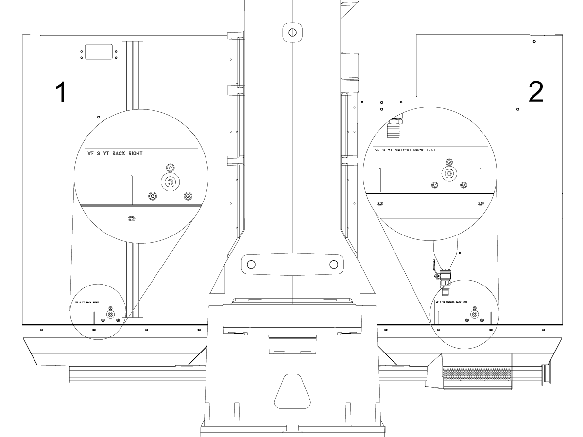
Chip Washdown Alignment Templates will help to place the chip washdown system in the correct location on your machine. 

For the placement information below, please reference the image for the alignment section.

[1] Indicates the right side of the machine when facing the front of the machine.

[2] Indicates the left side of the machine when facing the front of the machine.

NOTE: The image shown references a VF-2YT. Be sure to use the correct alignment and template for your machine.

VMC Small Template Alignment

Use the chart to download the correct templates for your Small VMC Machine. Then, reference the images below to accurately place the template on the machine. 

Be sure the bottom edge of the template is aligned with the seam between the bottom pan and back panel, with the text facing right-side up. Use tape to secure the template in place so that it does not slide while marking or drilling the hole centers.

VMC SMALL
Machine Back Left Template Alignment Back Right Template Alignment
VF-1/2. VM-2 with 30 Pocket SMTC

VF-1/2, VM-2 - 30 Pocket SMTC

See Back Left Template Placement [3]

VF-1/2, VM-2

See Back Right Template Placement [4]

VF-1/2 YT with 30 Pocket SMTC

VF-1/2 YT - 30 Pocket SMTC

See Back Left Template Placement [3]

VF-1/2 YT

See Back Right Template Placement [4]

VF-1/2 YT, VM-2 with 50 Pocket SMTC

VF-1/2 YT, VM-2 - 50 Pocket SMTC

See Back Left Template Placement [3]

VF-1/2, VM-2

See Back Right Template Placement [4]

VF-1/2 YT with 70 Pocket SMTC

VF-1/2 YT - 70 Pocket SMTC

See Back Left Template Placement [3]

VF-1/2 YT

See Back Right Template Placement [4]

3. Back Left Template Placement: 

Align the right slot of the template above the 2nd screw from the left.

Align the left slot of the template above the 3rd screw from the left.


4. Back Right Template: 

Align the slot of the template above the second screw from the left. 

VMC Medium Template Alignment

Use the chart to download the correct templates for your Medium VMC Machine. Then, reference the images below to accurately place the template on the machine. 

Be sure the bottom edge of the template is aligned with the seam between the bottom pan and back panel, with the text facing right-side up. Use tape to secure the template in place so that it does not slide while marking or drilling the hole centers.

VF-3/4/YT
Machine Back Left Template Alignment Back Right Template Alignment
VF/3/4/YT with 30 Pocket SMTC

VF-3/4/YT - 30 Pocket SMTC

See Back Left Channel Corner Placement [5]

VF-3/4/YT

See Back Right Channel Edge Placement [9]

VF/3/4/YT with 70 Pocket SMTC

VF-3/4/YT - 70 Pocket SMTC

See Back Left Channel Edge Placement [6]

VF-3/4/YT

See Back Right Channel Edge Placement [9]

VF-3/4 UMB-20

UMB-20 VF-3/4 

See Back Left Channel Edge Placement [6]

VF-3/4/YT

See Back Right Channel Edge Placement [9]

VF-3/4 with 50 Pocket SMTC

VF-3/4 - 50 Pocket SMTC

See Back Left Channel Corner Placement [5]

VF-3/4/YT

See Back Right Channel Edge Placement [9]

VF-3 YT/40  with 50 Pocket SMTC

VF-3YT/40 - 50 Pocket SMTC

See Back Left Channel Corner Placement [5]

VF-3/4/YT

See Back Right Channel Edge Placement [9]

VF- 3 YT/50

VF-3YT/50

See Back Left Second Screw Placement [7]

VF-3YT/50

See Back Right Channel Edge Placement [9]

VF-5
Machine Back Left Template Alignment Back Right Template Alignment
VF-5/50

VF-5/50

See Back Left Channel Edge Placement [6]

VF-5/50

See Back Right Channel Edge Placement [9]

VF-5/40 with 30 Pocket SMTC

VF-5/40 - 30 Pocket SMTC

See Back Left Second Screw Placement [7]

VF-5/40

See Back Right Channel Edge Placement [9]

VF-5/40 with 50 Pocket SMTC

VF-5/40 - 50 Pocket SMTC

See Back Left Second Screw Placement [7]

VF-5/40

See Back Right Channel Edge Placement [9]

VF-5/40 with 70 Pocket SMTC

VF-5/40 - 70 Pocket SMTC

See Back Left Second Screw Placement [7]

VF-5/40

See Back Right Channel Edge Placement [9]

VF-5/40/XT with UMB 20 

UMB-20 VF-5/40/XT

See Back Left Channel Edge Placement [6]

VF-5/40

See Back Right Channel Edge Placement [9]

VP-5
Machine Back Left Template Alignment Back Right Template Alignment
VP-5

VP-5

See Back Left Channel Edge Placement [6].

VP-5

See Back Right Channel Corner Placement [10]

5. Back Left Channel Corner: 

Align the cutout of the template to the channel corner. 

6. Back Left Channel Edge: 

Align the template to the left or right side of the channel, as indicated on the template. 

7. Back Left Second Screw Placement:

Align the slot of the template above the second screw from the right. 

8. Back Left Chiller Stand Placement

Align the cutout of the template above the chiller stand. 

9. Back Right Channel Edge Placement

Align the side of the template along the channel edge, as indicated by the template. 

10. Back Right Channel Edge Placement

Align the cutout of the template along the channel corner, as indicated by the template. 

Installation

1

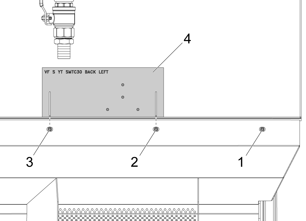
Use the provided hole template [4] on the left side on the outside of the back panel of the machine. 

Align the template so that the third screw [3] from the right is aligned with the left line of the template and the second screw [2] from the right is aligned with the right line of the template.

Be sure the bottom edge of the template is aligned with the seam between the bottom pan and back panel, with the text facing right-side up.

Use tape to secure the template in place so that it does not slide while marking or drilling the hole centers.

NOTE: The image shown references a VF-2YT. Be sure to use the correct alignment and template for your machine.

2

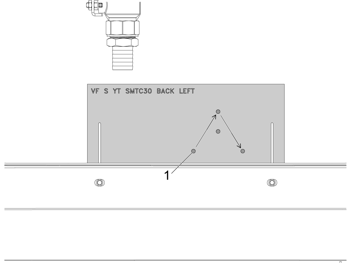
Use a center punch to mark the hole centers OR Use a 1/8" drill bit to drill pilot holes.

Use a 1/4" drill bit to drill holes starting with the first hole [1] and following in the pattern shown, without drilling the center hole.

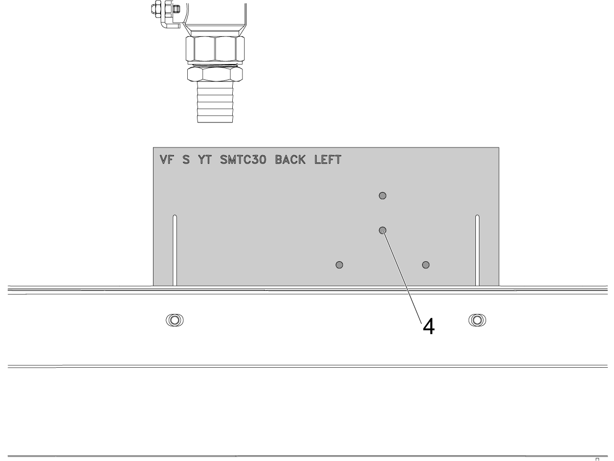
3

Drill a pilot hole to the minimum inner diameter of the step drill to the middle hole [4].

Use the step drill to drill a 1/2" diameter hole through the middle hole [4].

Be sure that the threads of the push-connect fitting fit through the hole.

4

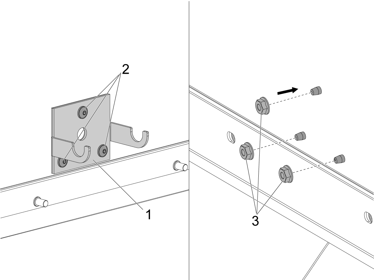
Use 3X of the 1/4-20 button-head screws (15/32" hex) [2] to install the support bracket [1] to the interior face of the back panel.

Use a 7/16" wrench to tighten the 3X flange nuts [3].

NOTE: A second person may be necessary to help tighten the screws.

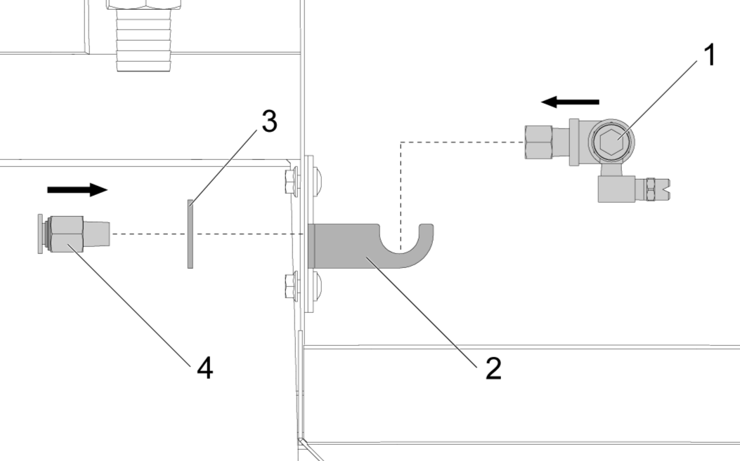
5

Insert the manifold [1] in the arms of the support bracket [2].

Use a washer [3] in-between the back panel and the push-connect fitting [4] and install the push-connect fitting through the back panel and thread into the tee of the manifold.

Tighten the push-connect fitting with an 11/16" wrench.

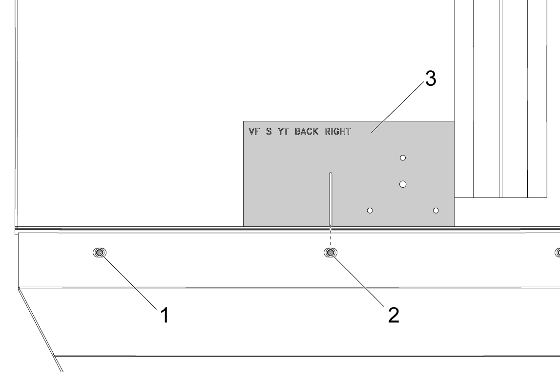
6

Use the provided hole template [1] on the right side on the outside of the back panel of the machine.

Align the hole template so the slot aligns vertically with the second screw [2] from the left that connects the bottom pan to the back panel.

Be sure the edge aligns with the support channel.

Repeat steps 1-5 for this side.

7

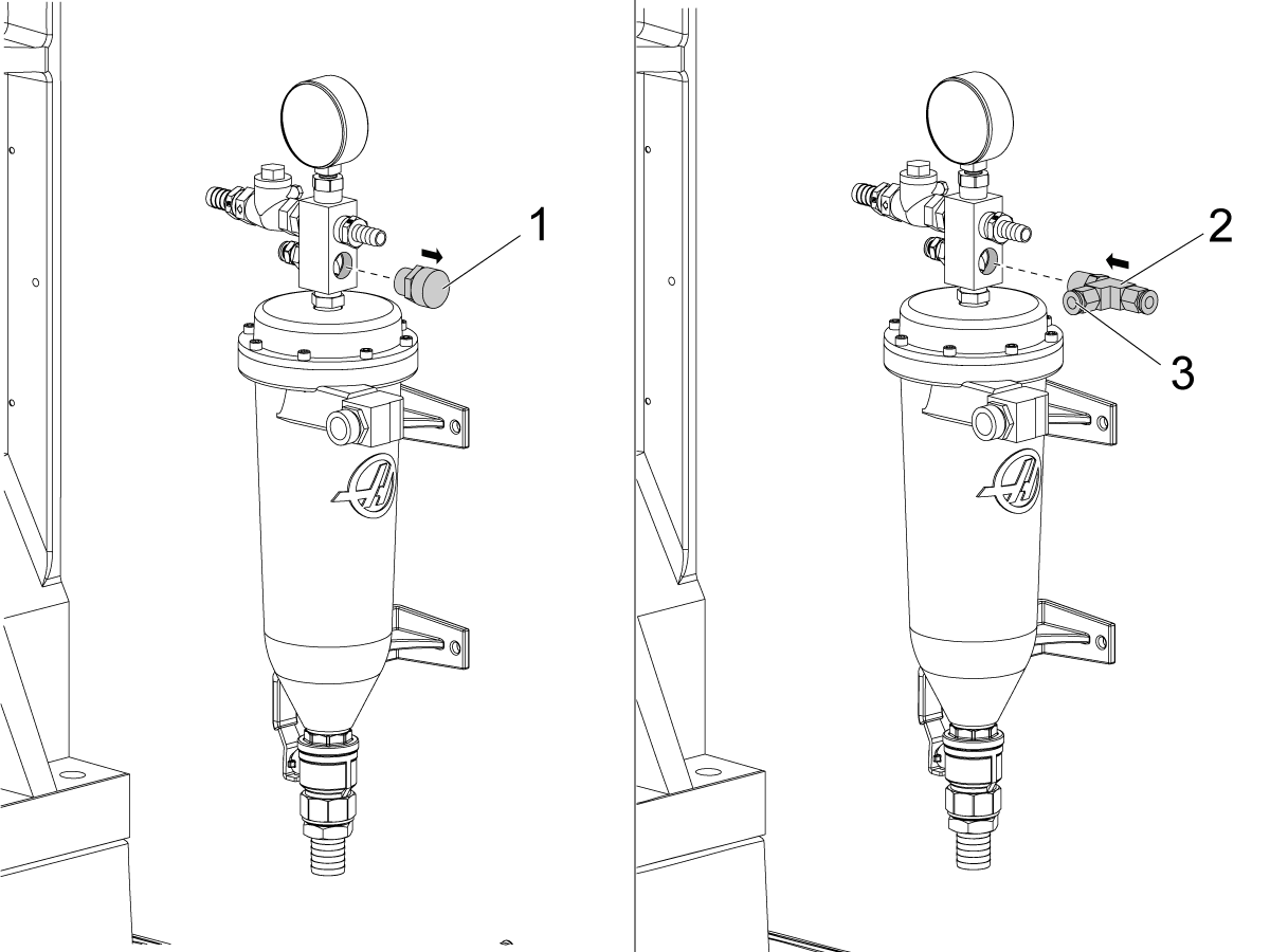
Use a 1-1/8" wrench to remove the garden hose cap [1] and fitting from the chip separator manifold and install the supplied tee fitting [2] with push-connect fittings.

NOTE: You may need to remove the bottom push connect fitting [3] in order to tighten the tee. Version B chip separators can skip this step.

8

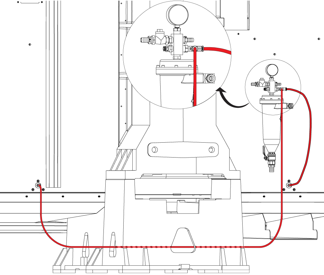
Route the supplied hoses as shown. Check if the hoses are properly installed by gently tugging at the base of the hose connected into the push-connect fittings.

NOTE: The 8-foot hose should be routed through the cutouts of the base casting. Excess hose lengths can be trimmed with a hose cutter, but ensure that the hoses are not tight or kinked. Do not trim hose at an angle.

9

To test if there are any leaks, turn on the coolant and check the push-connect fittings at the hose and threaded ends, support bracket, and tee fitting at chip separator manifolds.

Tighten fittings where necessary.

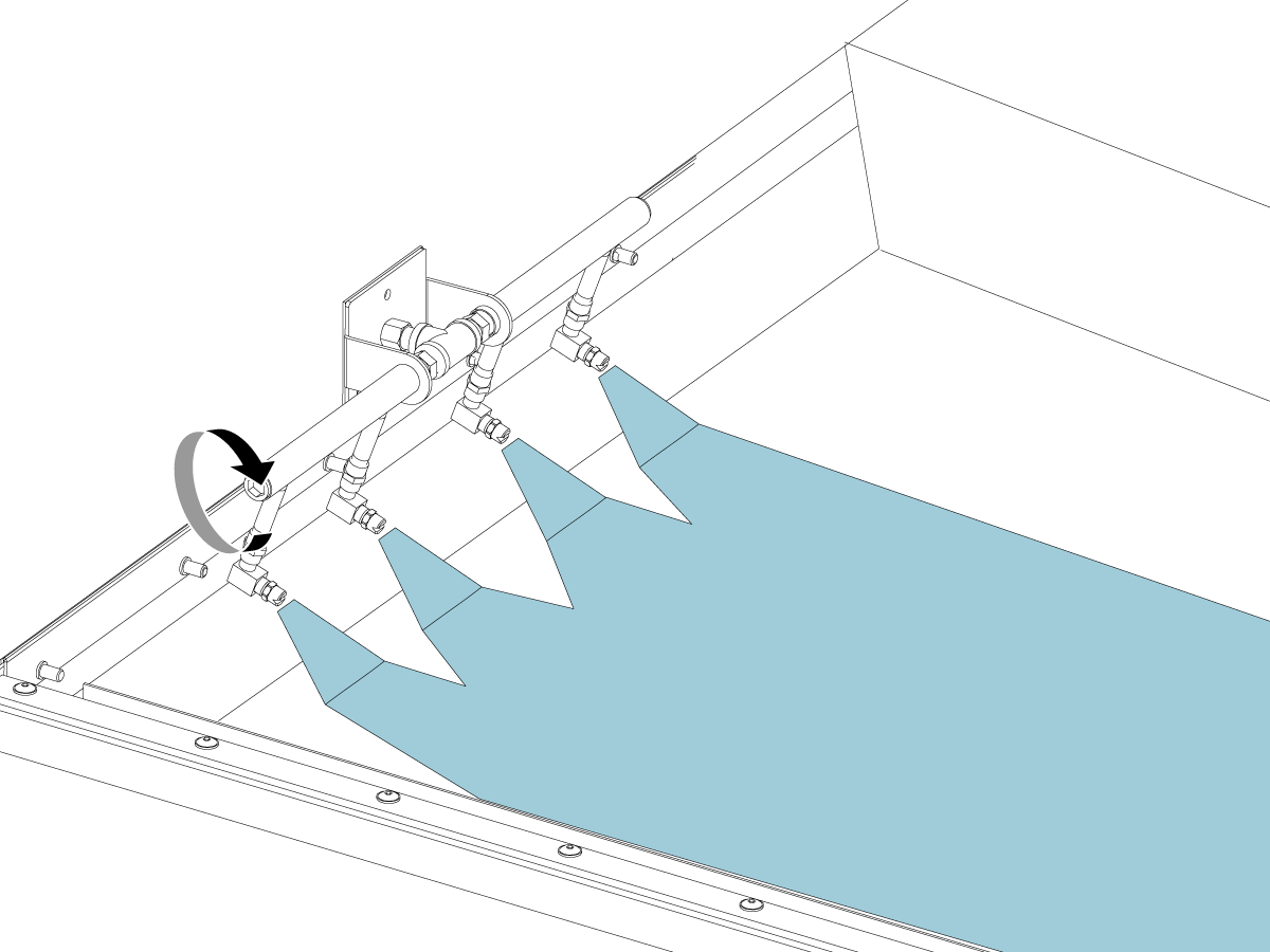
10

Angle the nozzles down at approximately a 45-degree angle. Ensure that the coolant nozzles do not hit the sheet metal.

  • Rotate the manifold [1] clockwise and counterclockwise by hand or with a hex bit on the plug end.
  • Rotate the steel fitting [2] clockwise and counterclockwise by hand or with a crescent wrench. 

NOTE: Loosening manifold or steel fitting excessively may result in reduced pressure and performance. Do not loosen too much.

11

For installation kits that come with the anti-rotation, flanged bracked [1], rotate the coolant nozzles until they're flush with the flange. This will hold the nozzles at the correct angle while coolant is flowing. . 

Test and Verification

1

Updated

Go to MDI and type in M08.

IMPORTANT:  VMC-6 models and larger are equipped with a dedicated chip washdown pump. For these machines, use M07 to activate the chip washdown system.

Press [Cycle Start]

Test the flow of coolant through the manifold. Coolant should form a continuous sheet along the bottom of the machine. 

Note: Coolant from nozzles should NOT be hitting the machine's table or saddle. 

Recently Viewed Items

You Have No Recently Viewed Items Yet

Feedback
Haas Logo

Haas Delivered Price

This price includes shipping cost, export and import duties, insurance, and any other expenses incurred during shipping to a location in France agreed with you as a buyer. No other mandatory costs can be added to the delivery of a Haas CNC Product.

KEEP UP WITH THE LATEST HAAS TIPS AND TECHNOLOGY...

Sign up now!   

HAAS TOOLING ACCEPTS THE FOLLOWING:

  • Service & Support
  • Owners
  • Request Service
  • Operator Manuals
  • Haas Parts
  • Rotary Repair Request
  • Pre-Install Guides
  • Shopping Tools
  • Build & Price a New Haas
  • Available Inventory
  • The Haas Price List
  • CNCA Financing
  • About Haas
  • Accessibility Statement
  • DNSH Statement
  • Export Compliance
  • Careers
  • Certifications & Safety
  • Contact Us
  • History
  • Terms & Conditions
  • Haas Tooling Terms & Conditions
  • Privacy
  • Warranty
  • Haas Community
  • Haas Certification Program
  • Haas Motorsports
  • Gene Haas Foundation
  • Haas Technical Education Community
  • Events
  • Join the Conversation
  • Facebook
  • X
  • Flickr
  • YouTube
  • LinkedIn
  • Instagram
  • TikTok
© 2026 Haas Automation, Inc – CNC Machine Tools
This site is protected by reCAPTCHA and the Google Privacy Policy and Terms of Service apply.

2800 Sturgis Rd., Oxnard, CA 93030
Toll Free: (888) 817-4446 / Fax: 805-278-8554