My Haas Welcome,
!
Haas Tooling MyHaas/HaasConnect Sign In Register Haas Tooling MyHaas/HaasConnect Sign Out Welcome, My Machines Latest Activity My Quotes My Account My Users Sign Out
Find Your Distributor
  1. Select Language
    1. English
    2. Deutsch
    3. Español - ES
    4. Español - MX
    5. Français
    6. Italiano
    7. Português
    8. Český
    9. Dansk
    10. Nederlands
    11. Magyar
    12. Polski
    13. Svenska
    14. Türkçe
    15. 中文
    16. Suomi
    17. Norsk
    18. الإنجليزية
    19. български
    20. Hrvatski
    21. Ελληνικά
    22. Română
    23. Slovenský
    24. Slovenščina
    25. 한국어
    26. 日本語
    27. Українська
  • machines Main Menu
    • Vertical Mills
      Vertical Mills
      Vertical Mills View All
      • Vertical Mills
      • VF Series
      • Universal Machines
      • VR Series
      • VP-5 Prismatic
      • Pallet-Changing VMCs
      • Mini Mills
      • Mold Machines
      • High-Speed Drill Centers
      • Drill/Tap/ Mill Series
      • Toolroom Mills
      • Pocket Mill
      • Compact Mills
      • Gantry Series
      • SR Sheet Routers
      • Extra-Large VMC
      • Double-Column Mills
      • 3+2 Positioning Machines
    • Multi-Axis Solutions
      Multi-Axis Solutions
      Multi-Axis Solutions View All
      • Multi-Axis Solutions
      • Y-Axis Lathes
      • 5-Axis Mills
    • Lathes
      Lathes
      Lathes View All
      • Lathes
      • ST Series
      • Dual-Spindle
      • Box Way Series
      • Toolroom Lathes
      • Chucker Lathe
      • Pocket Lathe
      • Haas Bar Feeders
    • Horizontal Mills
      Horizontal Mills
      Horizontal Mills View All
      • Horizontal Mills
      • 50-Taper
      • 40-Taper
    • Rotaries & Indexers
      Rotaries & Indexers
      Rotaries & Indexers View All
      • Rotaries & Indexers
      • Rotary Tables
      • Indexers
      • 5-Axis Rotaries
      • Extra-Large Rotaries
    • Special Series
      Special Series
      Special Series View All
      • Special Series
      • EU_Series_Redirect
    • Automation Systems
      Automation Systems
      Automation Systems View All
      • Automation Systems
      • Mill Automation
      • Lathe Automation
      • Automatic Parts Loaders
      • Automation Models
    • Desktop Machines
      Desktop Machines
      Desktop Machines View All
      • Desktop Machines
      • Desktop Mill
      • Desktop Lathe
      • Control Simulator, Standard
      • Control Simulator, Premium
    • Shop Equipment
      Shop Equipment
      Shop Equipment View All
      • Shop Equipment
      • Knee Mill
      • Haas Manual Lathes
      • Haas Saws
    • Fabrication Machines
      Fabrication Machines
      Fabrication Machines View All
      • Fabrication Machines
      • Laser Cutting Machines
      • CNC Press Brakes
    • QUICK LINKS Special Series  Special Series 
      EU SERIES EU SERIES BUILD & PRICE | PRICE LIST BUILD & PRICE | PRICE LIST In-Stock Machines In-Stock Machines WHAT’S NEW WHAT’S NEW YOUR FIRST CNC YOUR FIRST CNC
      SHOPPING TOOLS
      • Build & Price a Haas
      • Price List
      • Available Inventory
      • CNCA Financing
      WANT TO TALK TO SOMEONE?

      A Haas Factory Outlet (HFO) can answer your questions, and walk you through your best options.

      CONTACT YOUR DISTRIBUTOR >
  • Options Main Menu
    • The Haas Control Value Option Packages
      Value Option Packages
      Value Option Packages View All
      • Value Option Packages
    • Product Image Spindles
      Spindles
      Spindles View All
      • Spindles
    • Product Image Tool Changers
      Tool Changers
      Tool Changers View All
      • Tool Changers
    • Product Image 4th- | 5th-Axis
      4th- | 5th-Axis
      4th- | 5th-Axis View All
      • 4th- | 5th-Axis
    • Product Image Turrets & Live Tooling
      Turrets & Live Tooling
      Turrets & Live Tooling View All
      • Turrets & Live Tooling
    • Product Image Probing
      Probing
      Probing View All
      • Probing
    • Haas Chip & Coolant Management Chip & Coolant Management
      Chip & Coolant Management
      Chip & Coolant Management View All
      • Chip & Coolant Management
    • The Haas Control The Haas Control
      The Haas Control
      The Haas Control View All
      • The Haas Control
    • Product Image Product Options
      Product Options
      Product Options View All
      • Product Options
    • Product Image Tooling & Fixturing
      Tooling & Fixturing
      Tooling & Fixturing View All
      • Tooling & Fixturing
    • Product Image Workholding
      Workholding
      Workholding View All
      • Workholding
    • Product Image 5-Axis Solutions
      5-Axis Solutions
      5-Axis Solutions View All
      • 5-Axis Solutions
      • 5 Easy Steps to 5-Axis
    • QUICK LINKS Special Series  Special Series 
      EU SERIES EU SERIES BUILD & PRICE | PRICE LIST BUILD & PRICE | PRICE LIST In-Stock Machines In-Stock Machines WHAT’S NEW WHAT’S NEW YOUR FIRST CNC YOUR FIRST CNC
      SHOPPING TOOLS
      • Build & Price a Haas
      • Price List
      • Available Inventory
      • CNCA Financing
      WANT TO TALK TO SOMEONE?

      A Haas Factory Outlet (HFO) can answer your questions, and walk you through your best options.

      CONTACT YOUR DISTRIBUTOR >
  • Why Haas Main Menu
      Discover the Haas Difference
    • Why Haas
    • MyHaas
    • Education Community
    • Industry 4.0
    • Haas Certification
    • Customer Testimonials
  • Service Main Menu
      Welcome to Haas Service
      SERVICE HOME Operator’s Manuals How-To Procedures Troubleshooting Guides Preventive Maintenance Haas Parts Haas Tooling Videos
  • Videos Main Menu
  • Main Menu
    • View All
    • View All
    • View All
    • View All
      • HTEC Curriculum Support
      • Haas Value Option Packages (VOP) Journey
    • View All
      • Haas 10 kg Cobot Package
      • Cobot Kits
      • DC-1 Drill Center
      • CNC Sales News
      • Do More With Your Haas
    • View All
    • View All
      • contact-us-test
      • 4 - AUTOMATION SYSTEMS
      • Carousel-V2
      • expert test
      • Demo_Day_Trident-test
      • Link Test
      • image-sale-tag-test
      • article-list-test
      • Haas 25 kg Robot Package
      • test-algolia-page
    • View All
    • View All
    • View All
    • View All
      • calc-test
    • View All
    • QUICK LINKS Special Series  Special Series 
      EU SERIES EU SERIES BUILD & PRICE | PRICE LIST BUILD & PRICE | PRICE LIST In-Stock Machines In-Stock Machines WHAT’S NEW WHAT’S NEW YOUR FIRST CNC YOUR FIRST CNC
      SHOPPING TOOLS
      • Build & Price a Haas
      • Price List
      • Available Inventory
      • CNCA Financing
      WANT TO TALK TO SOMEONE?

      A Haas Factory Outlet (HFO) can answer your questions, and walk you through your best options.

      CONTACT YOUR DISTRIBUTOR >
  • Haas Tooling Main Menu
  • Haas Service Parts Main Menu

My Haas Welcome,
!
Haas Tooling MyHaas/HaasConnect Sign In Register Haas Tooling MyHaas/HaasConnect Sign Out Welcome, My Machines Latest Activity My Quotes My Account My Users Sign Out
Find Your Distributor
  1. Select Language
    1. English
    2. Deutsch
    3. Español - ES
    4. Español - MX
    5. Français
    6. Italiano
    7. Português
    8. Český
    9. Dansk
    10. Nederlands
    11. Magyar
    12. Polski
    13. Svenska
    14. Türkçe
    15. 中文
    16. Suomi
    17. Norsk
    18. الإنجليزية
    19. български
    20. Hrvatski
    21. Ελληνικά
    22. Română
    23. Slovenský
    24. Slovenščina
    25. 한국어
    26. 日本語
    27. Українська
×

Search Results

Web Pages

Images

    • <
    • 1
    • >

3 - Umbrella Tool Changer - Service Replacements

Mill Tool Changer - Service Manual


  • 0 - Mill Tool Changer - Table of Contents
  • 1 - Mill Tool Changer - Introduction
  • 2 - Mill Tool Changer - Overviews
  • 3 - Umbrella Tool Changer - Service Replacements
  • 4 - Umbrella Tool Changer - Alignment
  • 5 - Side Mount Tool Changer - Service Replacements
  • 6 - Side Mount Tool Changer - Alignment
  • 7 - Double Arm and Cambox - Service Replacements
  • 8 - Track Tool Changer - Service Replacements
  • 9 - Tool Changer - Troubleshooting Guides
  • 10 - Side-mount Tool Changer - Maintenance

Go To :

  • 3.1 Shuttle Roller - Replacement
  • 3.2 Removable Geneva Drive Carousel Motor - Replacement
  • 3.3 Pocket - Replacement
  • 3.4 Carousel Plate - Replacement
  • 3.5 Guide Pin and Trap Door - Replacement
  • 3.6 Slip Clutch Arm and Shuttle Motor - Replacement
  • 3.7 20/32 - Pocket Carousel - Motor Replacement
  • 3.8 10-Pocket Carousel - Motor Replacement

3.1 Umbrella Tool Changer - Shuttle Roller - Replacement

Recently Updated

Umbrella Tool Changer - Shuttle Roller - Replacement


Revision C - 4/2025

Shuttle Roller - Replacement - Introduction

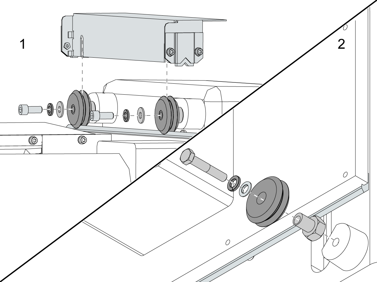
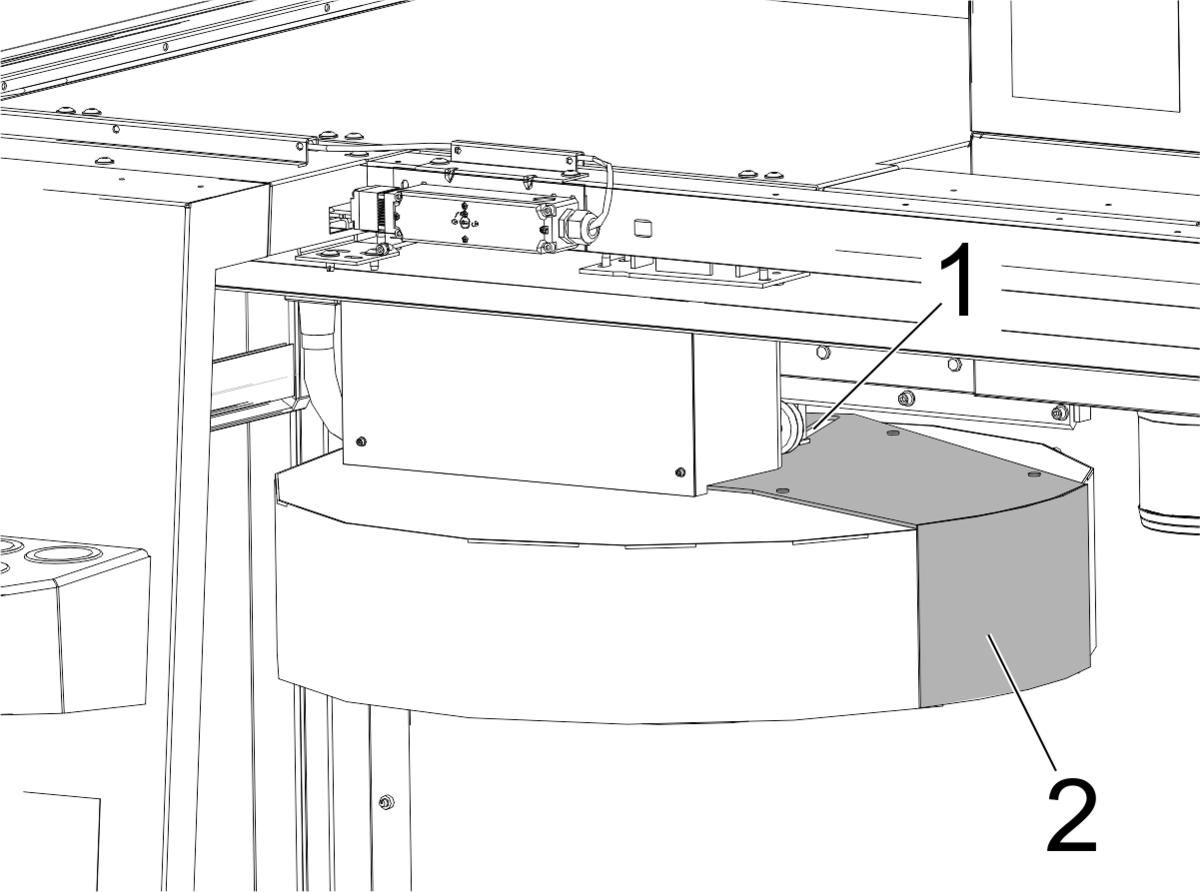
This procedure tells you how to replace the top [1] and bottom [2] shuttle rollers on an umbrella tool changer.

Tools Required:
  • Mobil 460 Grease
  • Bottle Jack
  • Medium-strength thread-lock compound

Shuttle Roller - Replacement

1

Remove all tools from the tool changer.

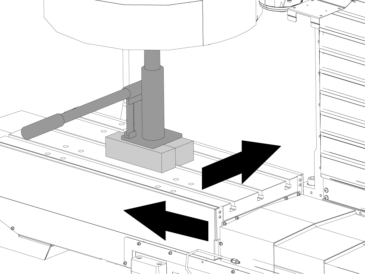
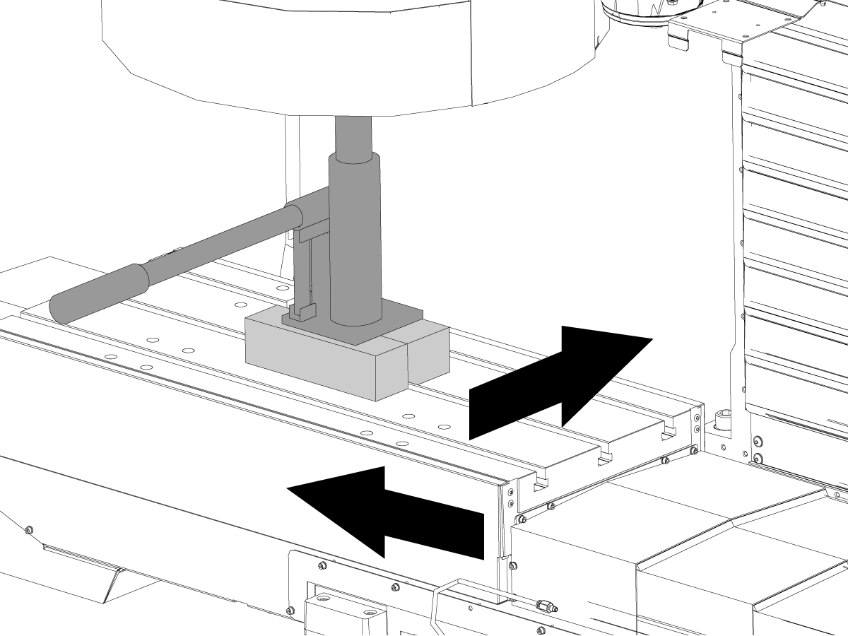
Put wooden blocks on the table. Put a bottle jack on the wooden blocks.

Jog the table below the center of the carousel plate.

Support the carousel plate with the bottle jack.

Push [POWER OFF]. Set the main circuit breaker to the OFF position. Lock the main circuit breaker. Use an approved lock with an approved safety tag.

2

Top roller replacement:

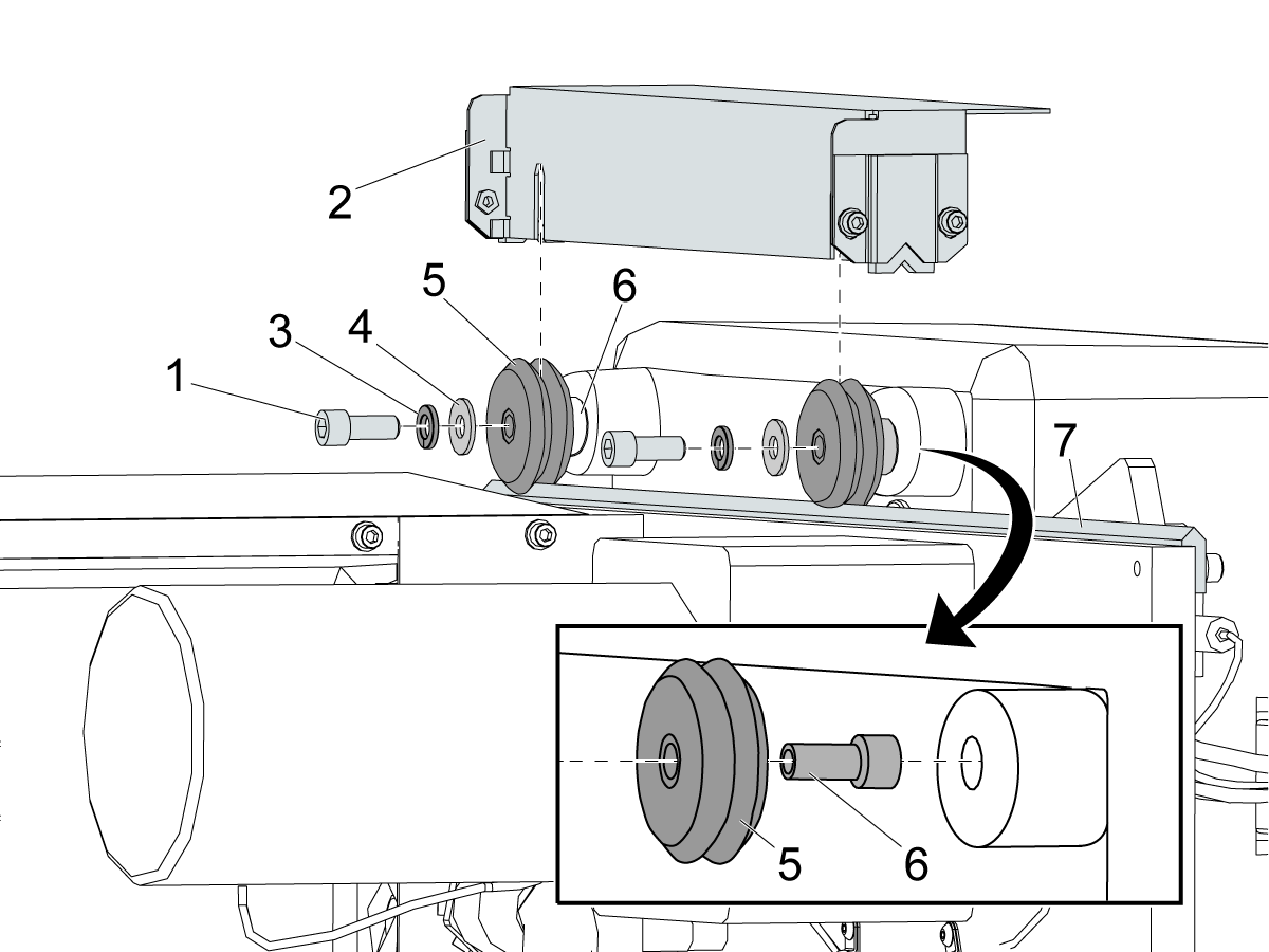
Loosen the (2) 5/16-18 x 2 Socket Head Cap Screws (SHCS) [1]. Remove the wiper bracket [2].

Remove the SHCS [1], lock washer [3], flat washer [4], and roller [5].

Apply medium-strength thread-lock compound (for example, blue Loctite®) to the (2) SHCS [1]. Replace the roller [5] and bushing [6]. Install the components in the opposite sequence they were removed. Make sure the roller [5] is tight against the V-rail [7].

Torque the SHCS [1] to 20 ft-lb (27 N-m). Apply Mobil 460 grease to the top V-rail [7].

3

Bottom roller replacement:

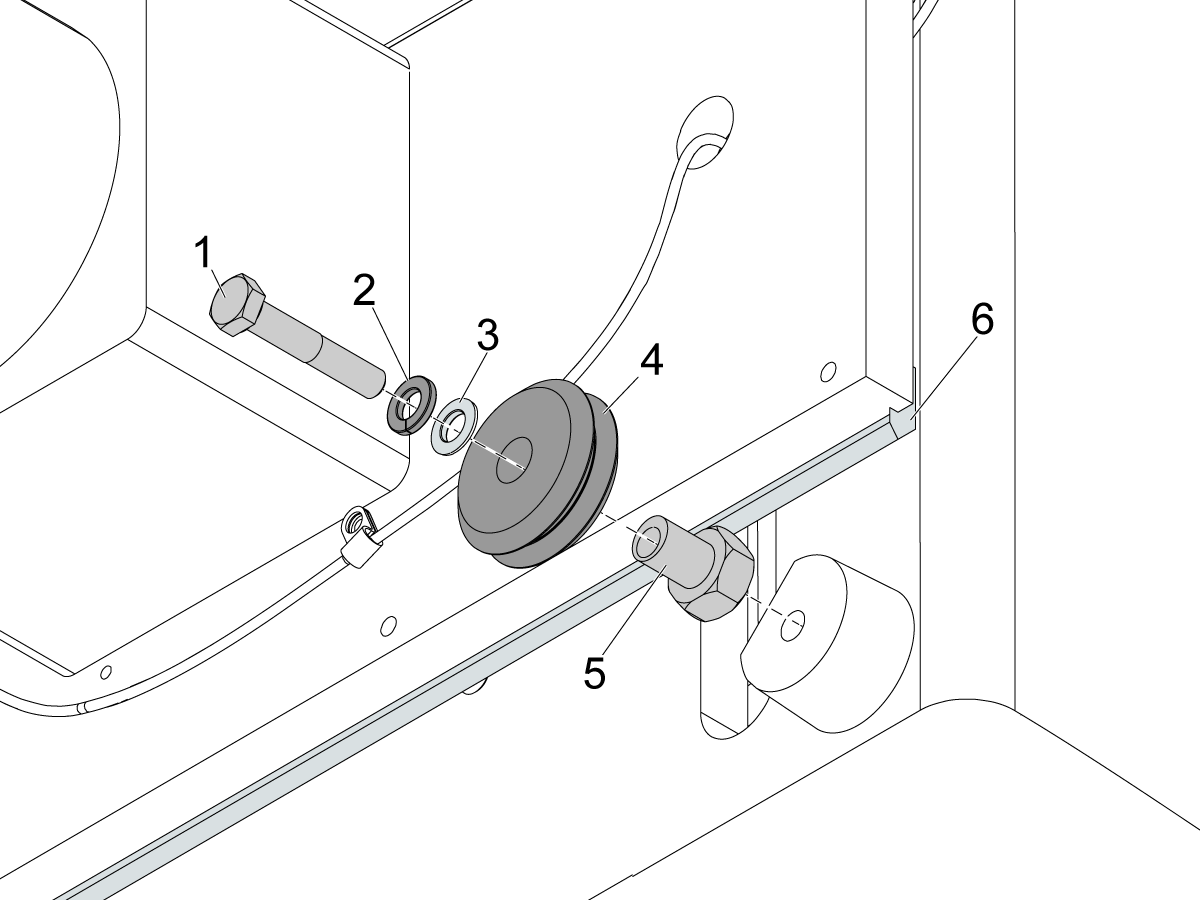
Remove the 5/16-18 x 1 3/4 Hex Head Bolt (HHB) [1], lock washer [2], flat washer [3], and roller [4].

Apply medium-strength thread-lock compound (for example, blue Loctite®) to HHB. Replace the roller [4] and eccentric bushing [5]. Install the components in the opposite sequence they were removed. Make sure the roller [4] is tight against the V-rail [6].

Rotate the eccentric bushing [5] until the roller is tight on the rail.

Torque the HHB [1] to 20 ft-lb (27 N-m). Apply Mobil 460 grease to the bottom V-rail [6].

IMPORTANT: Hold the lower guide bushing in place with a wrench while torquing the HHB. Over-torquing will cause damage to HHB and eccentric bushing.

Verification

1

Test the umbrella tool changer for correct operation.

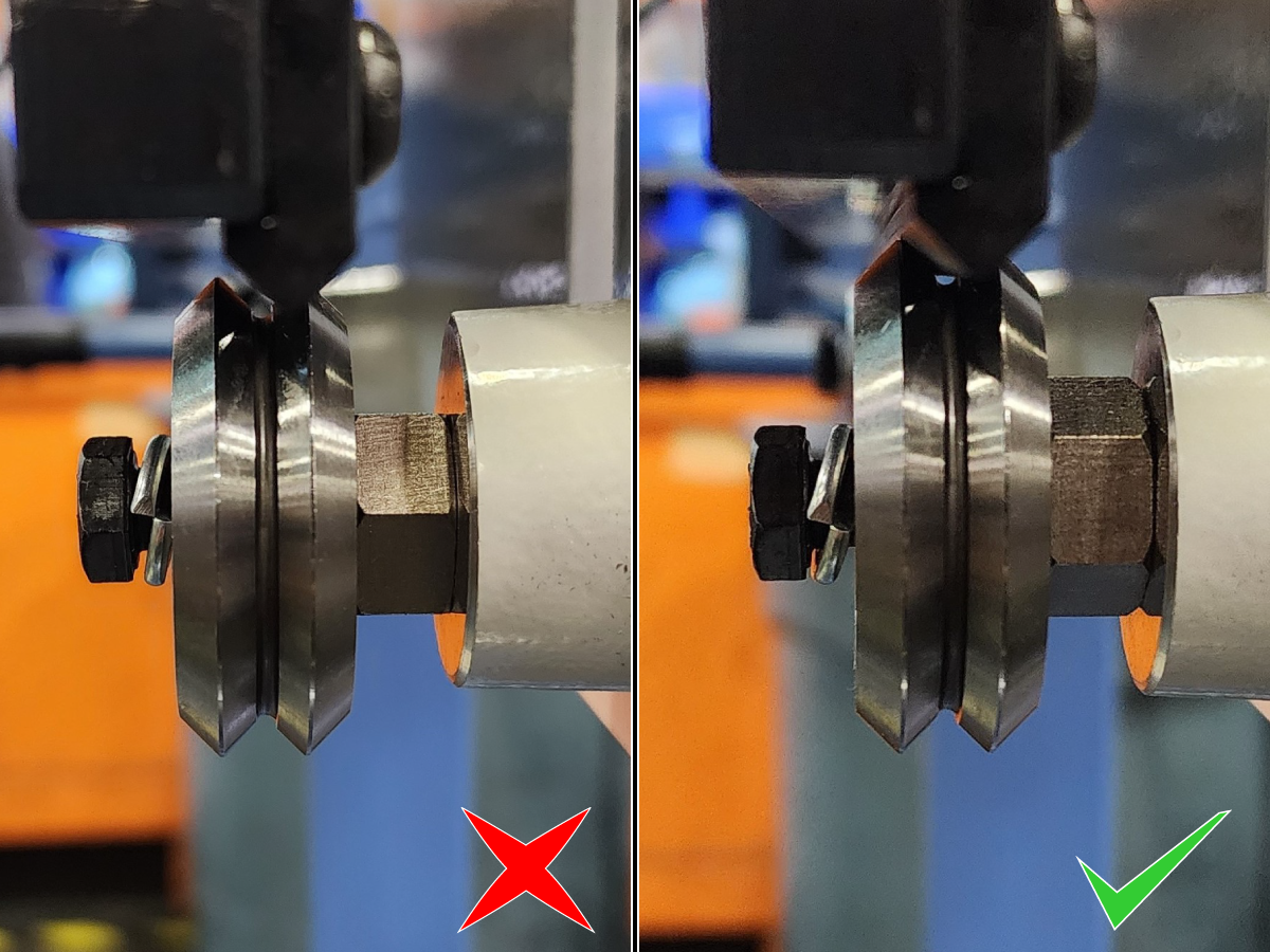
Visually inspect the roller to verify the carousel is not binding and is properly aligned as shown in the image.

2

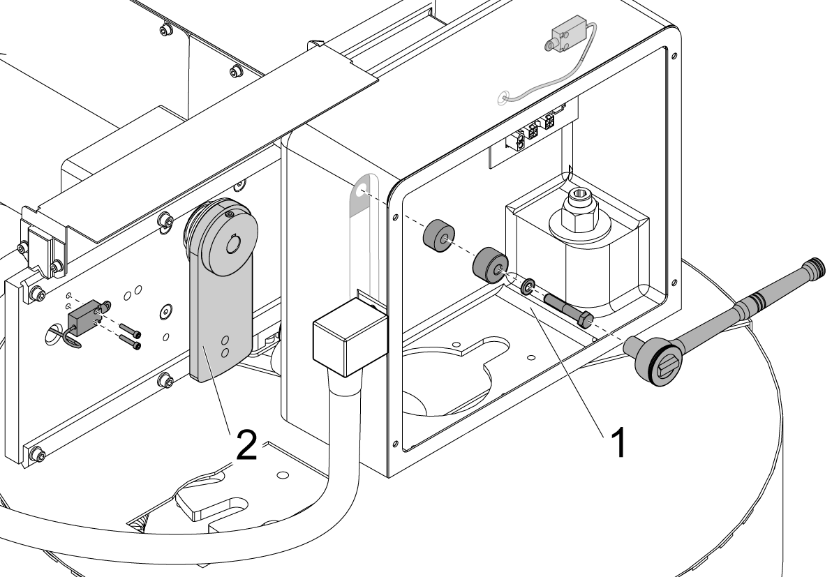
Remove the cam follower assembly [1] and lower the slip clutch arm [2] to move the carousel assembly from the shuttle in position, to the shuttle out position in order to verify there are no binds.

If the carousel does not bind, re-install the cam follower assembly.

Refer to the VMC - Umbrella Tool Changer to Spindle - Alignment procedure.

3.2 Umbrella Tool Changer - Removable Geneva Drive Carousel Motor - Replacement

Recently Updated

Umbrella Tool Changer - Removable Geneva Drive Carousel Motor - Replacement


Revision A 08/2025

Removable Geneva Drive Carousel Motor - Introduction

P/N 32-1900A CAROUSEL MOTOR GENEVA

Removable Geneva Drive Carousel Motor - Replacement

1

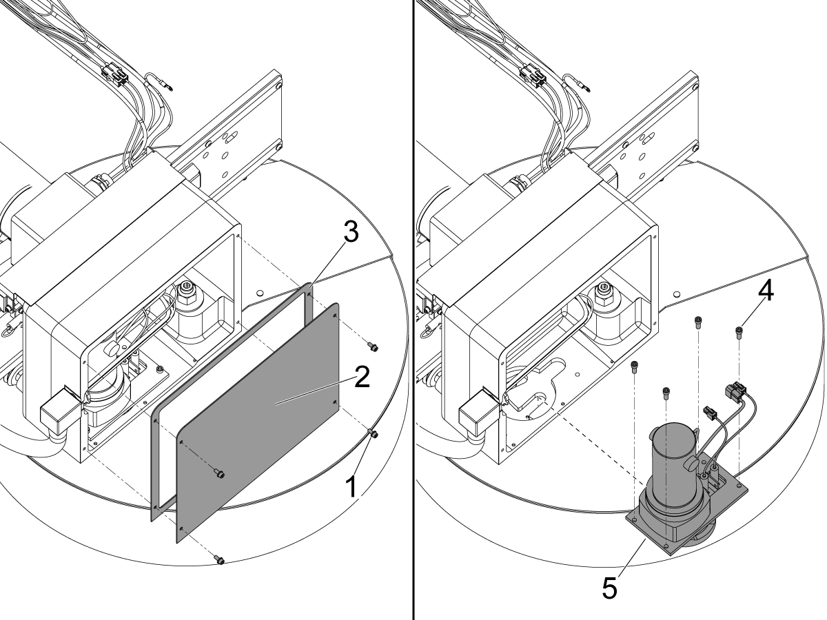
Remove the (4) 10-32 X 3/8 bolts [1] that attach the enclosure cover [2] and gasket [3] to the carousel motor enclosure.  Remove the enclosure cover [2] and gasket [3].

Unplug the sensor and motor cables.

Remove the (4) 1/4-20 X 5/8 bolts [4] that attach the carousel motor assembly [5] to the carousel motor enclosure.  Lift the carousel motor assembly [5] up and out of the carousel motor enclosure.

2

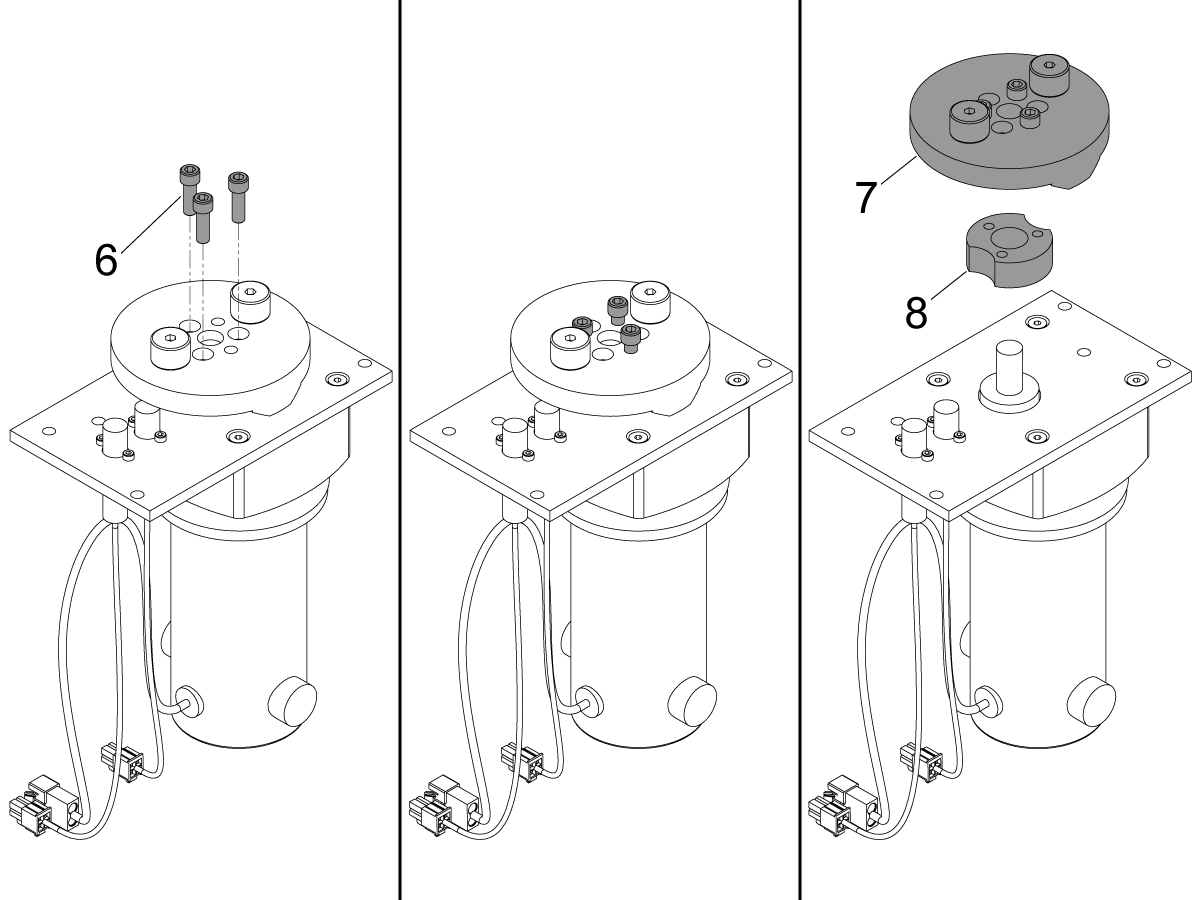
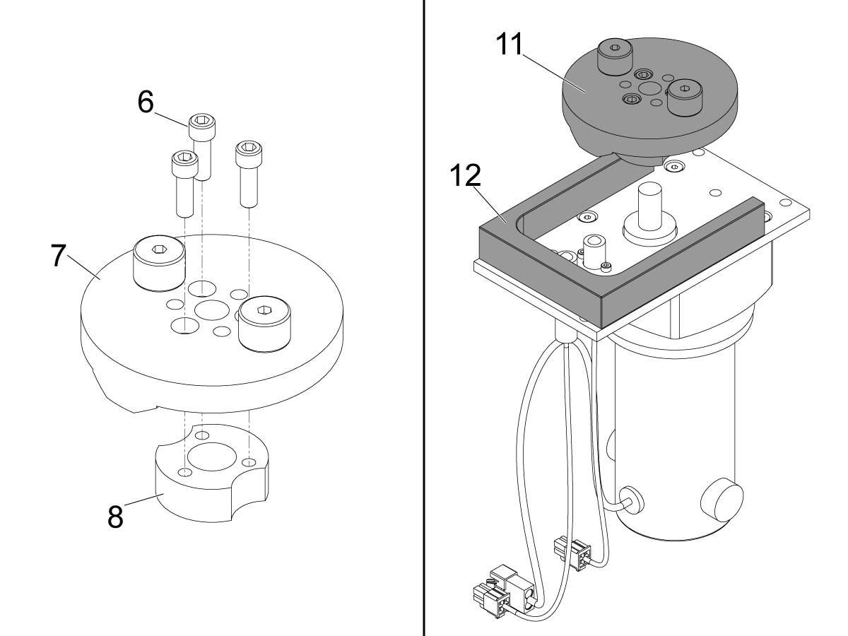
Prevent the geneva driver [7] from rotating by placing a screwdriver between the cam followers.  Break loose and remove the (3) 1/4-20 X 3/4 bolts [6].

Screw the (3) 1/4-20 X 3/4 bolts [6] into the threaded holes on the geneva driver [7].

Evenly tighten the (3) 1/4-20 X 3/4 bolts [6] until the geneva driver [7] and collar [8] unclamp from the motor shaft.

3

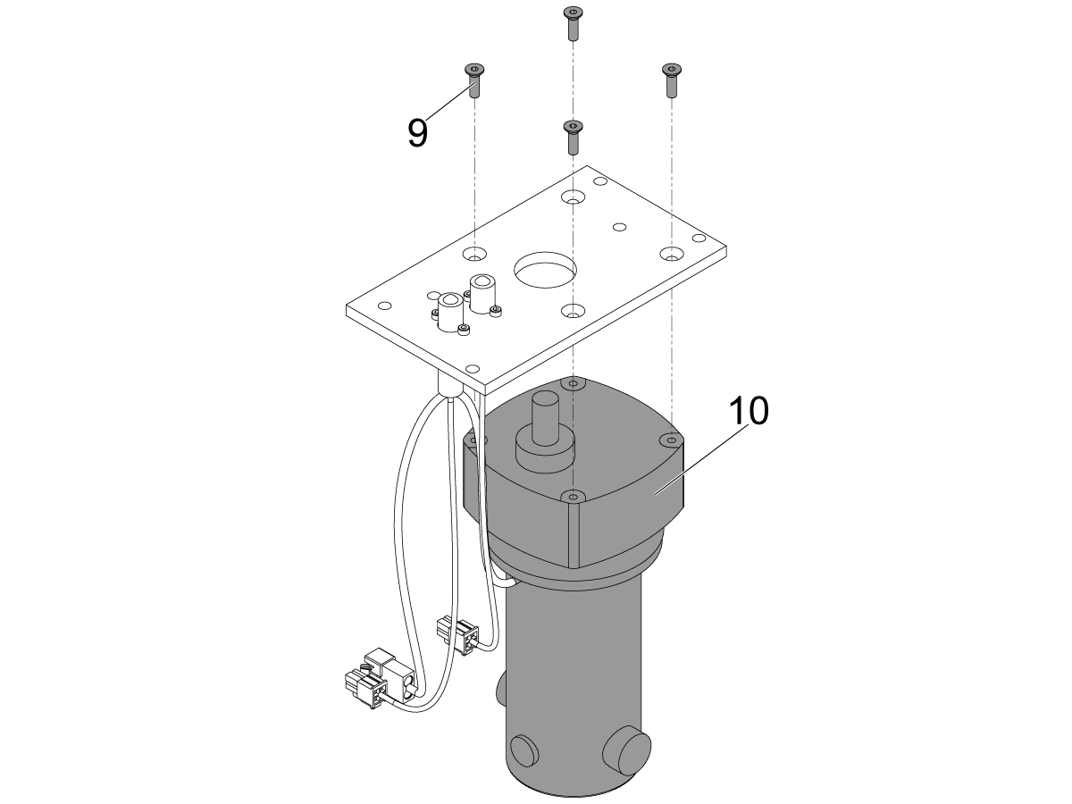
Unscrew and discard the (4) 10-32 X 5/8 machine screws [9].  Discard the broken carousel motor [10].

Note: The (4) 10-32 X 5/8 machine screws [9] are secured with red loctite.  Use an impact driver to remove them.

 Note: If the carousel motor assembly has limit switch instead of a proximity sensor lubricate the limit switch roller axel with a drop of gear oil.

Install the new carousel motor onto the the mounting plate.

4

Place the (3) 1/4-20 X 3/4 bolts [6] into the counter bored holes in the geneva driver [7] and screw them into the collar [8] a few threads.

Set the 2-Pin Geneva Drive Spacer Tool (T-2662)  [11] on the motor mounting plate as shown.

Install the geneva drive assembly [12] onto the motor shaft and orient it so that one of the flat sections at the top of the ramps is directly above the TT Clamp sensor.  Press down on the geneva drive assembly [12] until the flat sections at the bottom on the ramps are flush with the 2-Pin Geneva Drive Spacer Tool (T-2662) [11].

Prevent the geneva driver [7] from rotating by placing a screwdriver between the cam followers.  Torque the (3) 1/4-20 X 3/4 bolts [6] to 12 ft*lbs.

Remove the 2-Pin Geneva Drive Spacer Tool (T-2662) [11] and spin the geneva drive assembly [12].  Make sure it does not interfere with the proximity sensors.

Reinstall the carousel motor assembly, gasket, and enclosure cover.

3.3 Umbrella Tool Changer - Pocket - Replacement

Recently Updated

Umbrella Tool Changer - Pocket - Replacement


Applies to machines built from: January, 1989

Revision A 08/2025

Pocket - Replacement - Introduction

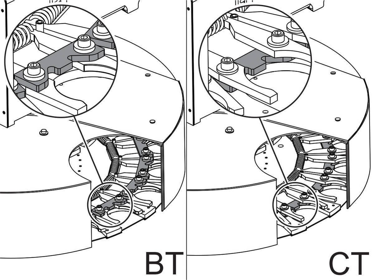
The illustrations in this procedure show a BT-style tool-changer. The instructions are the same for a CT-style tool-changer.
This procedure is applicable to more than one kit. Only one of the kits is necessary.

  • 93-2366 POCKET REPLACEMENT, BT UMBRELLA 32 STATION
  • 93-2371 POCKET REPLACEMENT, CT UMBRELLA 10 STATION (SMM & GR ONLY)
  • 93-2370 POCKET REPLACEMENT, BT UMBRELLA 10 STATION (SMM & GR ONLY)
  • 93-2373 POCKET REPLACEMENT, CT UMBRELLA 20 STATION (NOT GR)
  • 93-2372 POCKET REPLACEMENT, BT UMBRELLA 20 STATION (NOT GR)
  • 93-2369 POCKET REPLACEMENT, CT UMBRELLA 20 STATION (GR ONLY)
  • 93-2368 POCKET REPLACEMENT, BT UMBRELLA 20 STATION (GR ONLY)
  • 93-2374 POCKET REPLACEMENT, BT UMBRELLA 10 STATION (NOT SMM)
  • 93-2367 POCKET REPLACEMENT, CT UMBRELLA 32 STATION
  • 93-2375 POCKET REPLACEMENT, CT UMBRELLA 10 STATION (NOT SMM OR GR)

Umbrella Tool Changer - Pocket - Replacement

1

Remove all tools from the tool changer. Put wooden blocks on the table. Put a bottle jack on the wooden blocks.

Jog the table below the center of the carousel plate.

Support the carousel plate with the bottle jack.

Push [POWER OFF].

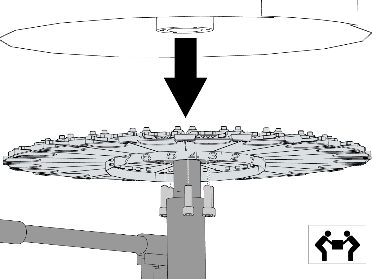
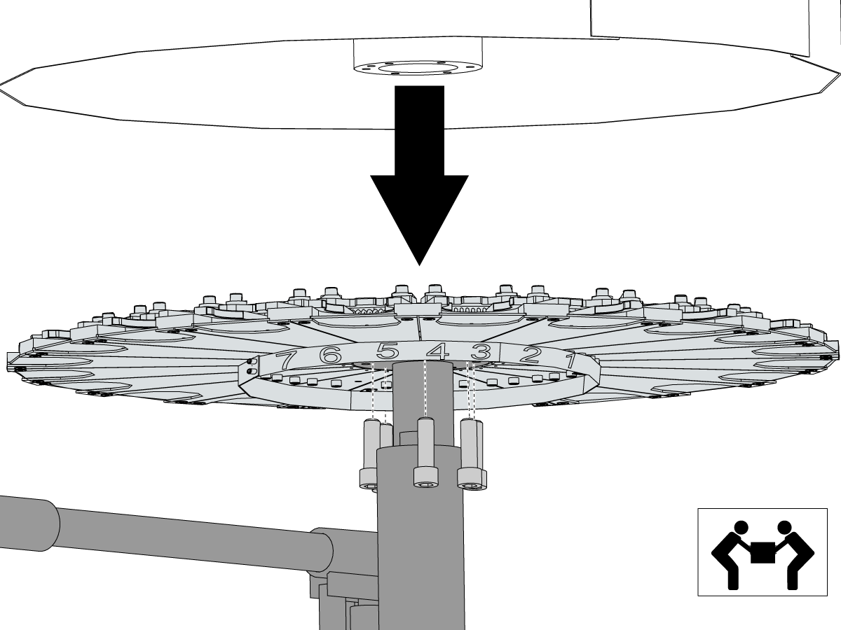
Remove the (6) SHCS from the carousel plate. With a second person remove the carousel plate.

2

Use your hand to push the station door [1] fully in to make sure it moves freely. If it does not move freely, clean the chips from the door and the door track.

Use a straightedge on the extractor fork [2] to see if it is bent.

Remove the screws [3] that attach the damaged fork assembly to the carousel plate. Remove the assembly as shown. Replace all damaged parts.

Apply a medium-strength thread-lock compound (for example, blue Loctite®) to the threads on the fork assembly screws [3]. Apply Mobil SHC grease to the thru-holes of the replacement assembly.

Install the replacement assembly. Make sure that the beveled side of the washer [4] is against the extractor key (BT, shown) or the fork bushing (CT). Torque the screws to 7 ft-lb (9.5 Nm).

3

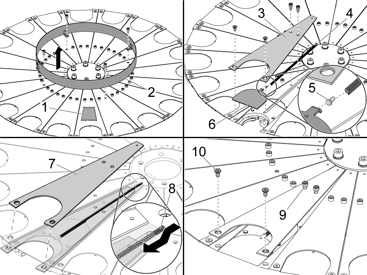
Put a piece of tape [1] on the carousel at pocket 1. Remove the pocket number ring [2].

Remove the sliding panel cover [3], compression spring [4], rivet [5], and sliding panel [6]. Replace all damaged parts. Clean all debris from the pocket.

Apply Mobil SHC-460 grease to the new compression spring. Put the 3/32" rivet into the end of the compression spring. Install the new compression spring [4] and new sliding panel [6]. Install the new sliding panel cover [7] while you push the end of the spring [8] under the panel.

Torque the (2) 10-32 SHCS [9] to 20 in-lb (2.26 Nm).

Apply medium-strength thread-lock compound (for example, blue Loctite®) to the (2) 10-32 flat head cap screws (FHCS) [10]. Install the (2) FHCS [10] and torque to 20 in-lb (2.26 Nm). Make sure the sliding panel [6] moves freely.

Install the pocket number ring [2]. Make sure the number 1 on the number ring aligns with the tape [1] on pocket 1 of the umbrella tool changer.

3.4 Umbrella Tool Changer - Carousel Plate - Replacement

Recently Updated

Umbrella Tool Changer - Carousel Plate - Replacement


AD0284

Revision B - 06/2026

Introduction

Updated

This procedure will show you how to replace the carousel plate on a umbrella style tool changer.

Note: The carousel plate is heavy. You must have the aid of one more person to help you lift it.

This document applies to the following service kits:

  • 30-0017A    CAROUSEL COMPLETE, 20 POCKET CT50
  • 93-1000374    BT TO CT CONV UMB 10 PCKT 40T
  • 93-1000375    CT TO BT CONV UMB 10 PCKT 40T 
  • 93-1000376    BT TO CT CONV UMB 20 PCKT 40T
  • 93-1000377    CT TO BT CONV UMB 20 PCKT 40T 
  • 93-1718    CAROUSEL COMPLETE, 10 POCKET BT40 W/COVERS   
  • 93-30-0006    CAROUSEL COMPLETE, 32 POCKET CT40  (VR-6-11)
  • 93-30-7100A CAROUSEL COMPLETE, 16 POCKET CT40
  • 93-8001    CAROUSEL COMPLETE, 20 POCKET CT40        
  • 93-8001BT    CAROUSEL COMPLETE, 20 POCKET BT40    

Carousel Plate - Replacement

1

Remove all tools from the tool changer.

Put wooden blocks on the table. Put a bottle jack on the wooden blocks.

Jog the table below the center of the carousel plate.

Support the carousel plate with the bottle jack.

2

Push [POWER OFF].

Remove the (6) SHCS from the carousel plate.

With a second person remove the carousel plate.

3

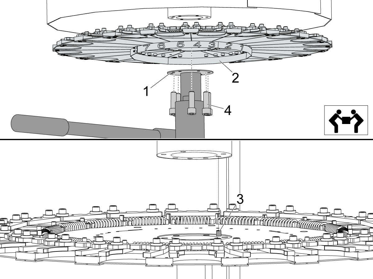
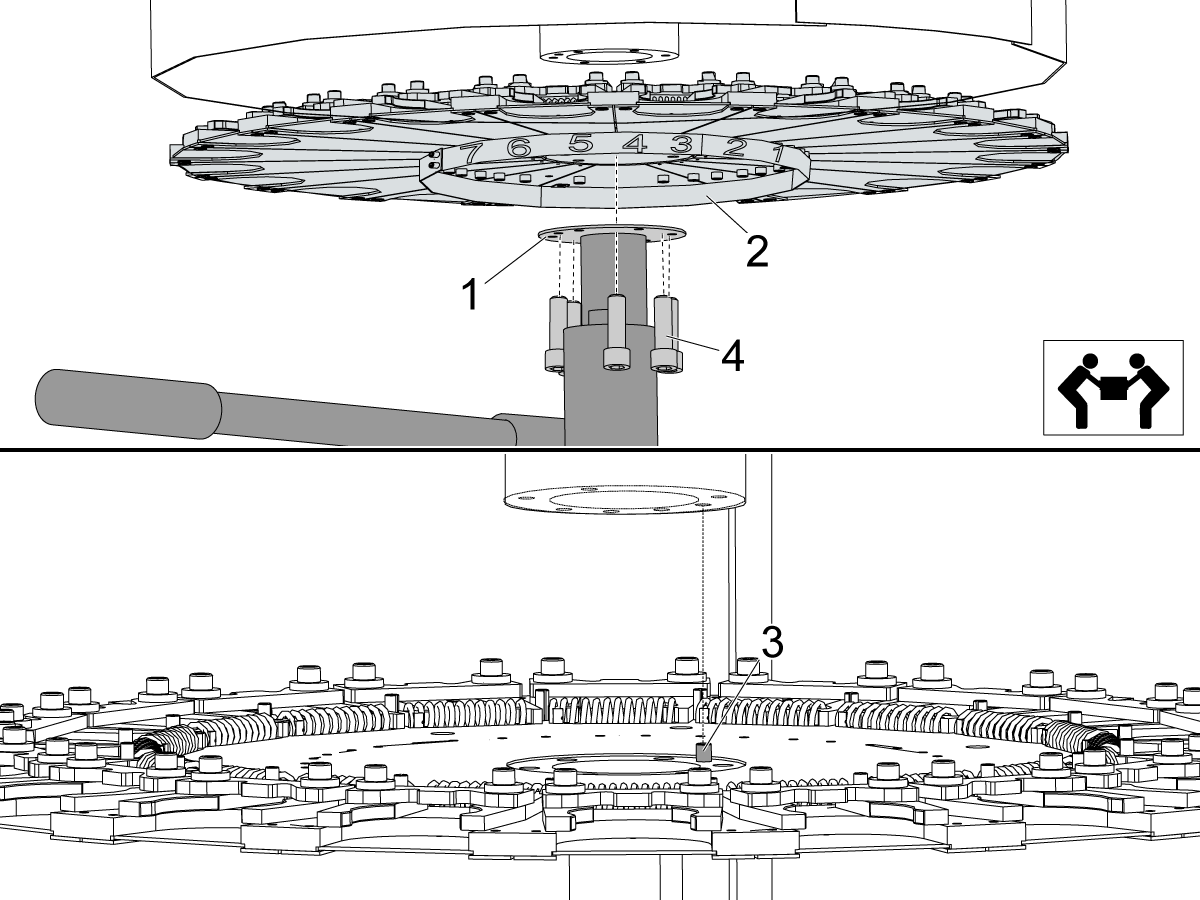
If necessary remove the old cover plate [1] and install it on the new carousel plate [2].

With the aid of a second person, put the new carousel plate [2] and the cover plate [1] onto the bottle jack. While the second person balances the new carousel plate [2] on the jack, do these steps:

  • Lift the new carousel plate [2] to the threaded holes. Align the dowel pin [3] to the hole in the bearing housing.
  • Install the (6) 5/16-18 x 1" Socket Head Cap Screws (SHCS) [4].

Torque the screws to 25 ft-lbs.

4

Push [POWER ON].

Check the tool changer alignment. Refer to Umbrella Tool Changer to Spindle Alignment.

Install the tools.

3.5 Umbrella Tool Changer - Guide Pin and Trap Door - Replacement

Recently Updated

Umbrella Tool Changer - Guide Pin and Trap Door - Replacement


Revision A 08/2025

Guide Pin and Trap Door - Introduction

This procedure tells you how to replace the guide pin [1] and trap door [2] on a umbrella tool changer.

Tools Required

  • Mobil 460 Grease
  • Bottle Jack

Umbrella Tool Changer - Guide Pin and Trap Door - Replacement

1

Remove all tools from the tool changer. Put wooden blocks on the table. Put a bottle jack on the wooden blocks.

Jog the table below the center of the carousel plate.

Support the carousel plate with the bottle jack.

Push [POWER OFF].

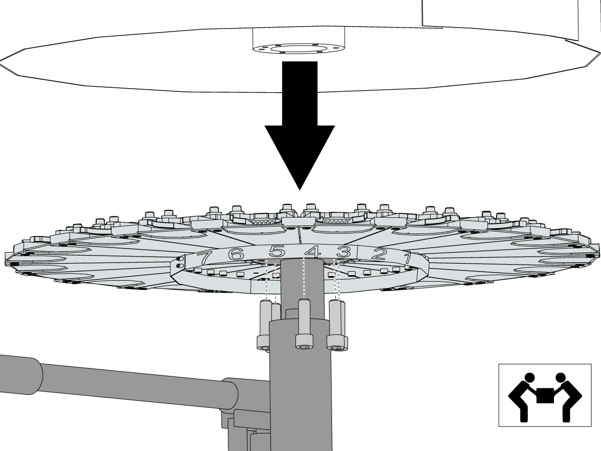
Remove the (6) SHCS from the carousel plate. With a second person remove the carousel plate.

Raise the bottle jack up to support the weight of the bearing housing for the star assembly.

2

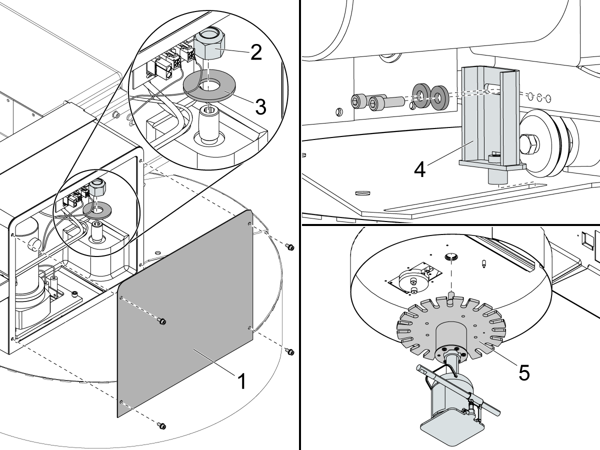
Remove the cover panel [1]. Remove the vertical axle nylon nut [2] and the flat washer [3]. Remove the guide pin assembly [4] from the trap door cover, behind the carriage assembly. Replace the guide pin assembly [4] if it is damaged.

Lower the bearing housing for the star assembly [5] and remove it from the machine.

3

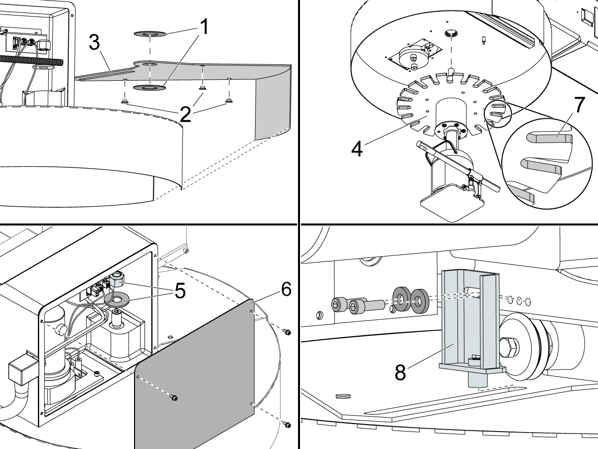
Remove the trap door, the (2) nylon washers [1] from the top and bottom of the trap door, and the (3) plastic riders [2] from the bottom of the trap door. Replace the washers [1] and the riders [2] if they are damaged.

Apply Mobil 460 grease to the nylon washers [1], plastic riders [2], and the trap door guide slot [3]. Install the washers [1], riders [2], and the new trap door.

Install the bearing housing for the star assembly [4]. Install the vertical axle nylon nut and flat washer [5] in the carriage assembly. Install the cover panel [6]. Apply Mobil 460 grease the tool slots [7] on the star assembly.

Install the guide pin assembly [8].

4

With the aid of a second person, put the carousel plate [2] and the cover plate [1] onto the bottle jack. While the second person balances the carousel plate [2] on the jack:

  • Lift the carousel plate [2] to the threaded holes. Align the dowel pin [3] to the hole in the bearing housing.
  • Install the (6) 5/16-18 x 1" Socket Head Cap Screws (SHCS) [4].

Torque the screws to 25 ft-lbs.

5

Perform the VMC - Umbrella Tool Changer to Spindle - Alignment procedure.

Test the umbrella tool changer for correct operation.

3.6 Umbrella Tool Changer - Slip Clutch Arm and Shuttle Motor - Replacement

Recently Updated

Umbrella Tool Changer - Slip Clutch Arm and Shuttle Motor - Replacement


AD0586

Revision A 08/2025

Introduction

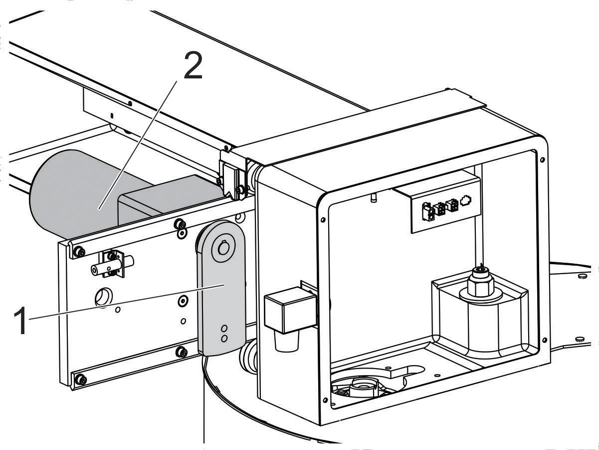
This procedure is applicable to 10- and 20-pocket umbrella tool changers. This procedure tells you how to replace the slip clutch arm [1] and the shuttle motor [2]. The illustrations show a 20-pocket umbrella tool changer.


Document applies to these parts:

  • 93-2597
  • 32-0011
  • 93-30-30061
  • 93-1790
  • 93-30-1937
  • 30-0019B

Tools Rquired:

  • Two-Jaw puller
  • Mobil SHC 460 Grease
  • Medium Strength thread-lock Compound

Replacement

1

Push [POWER OFF]. Set the main circuit breaker to the OFF position. Lock the main circuit breaker. Use an approved lock with an approved safety tag.

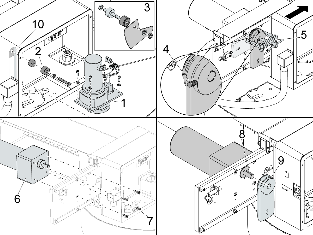
Remove the cover for the carousel motor. Put labels on the cables for the carousel motor assembly. Remove the carousel motor assembly [1]. Remove the cam follower assembly [2]. On 10-pocket umbrella tool changers, the cam follower assembly also has a flag and a nut [3] behind the carriage.

Push the shuttle assembly in the direction of the spindle. Remove the set screw [4] from the slip clutch arm collar. Use a small two-jaw puller [5] to remove the slip clutch arm from the motor shaft.

Remove the shuttle motor assembly [6] and (4) screws [7] from the rail plate. Apply a thread-lock compound (for example: blue Loctite®) to the (4) screws [7]. Install the replacement motor [6] to the rail plate. Use the (4) screws [7].

Install the motor key [8] onto the motor shaft. Install the slip clutch arm [9] onto the motor shaft, over the key [8]. Adjust the position of the slip clutch arm on the motor shaft to make sure the adjacent screw heads have sufficient clearance. Apply a thread-lock compound (for example: blue Loctite®) to the set screw [4]. Install the set screw into the slip clutch arm [9].

Apply Mobil SHC 460 grease to the carriage slot [10] and cam follower [2 and 3]. Install the remaining parts in the opposite sequence that they were removed. Make sure the umbrella tool changer operates correctly. Install the carriage assembly cover.

3.7 Umbrella Tool Changer - 20/32 - Pocket Carousel - Motor Replacement

Recently Updated

Umbrella Tool Changer - 20/32 - Pocket Carousel - Motor Replacement


AD0295

Revision A 08/2025

20/32 - Pocket Carousel - Motor - Replacement - Introduction

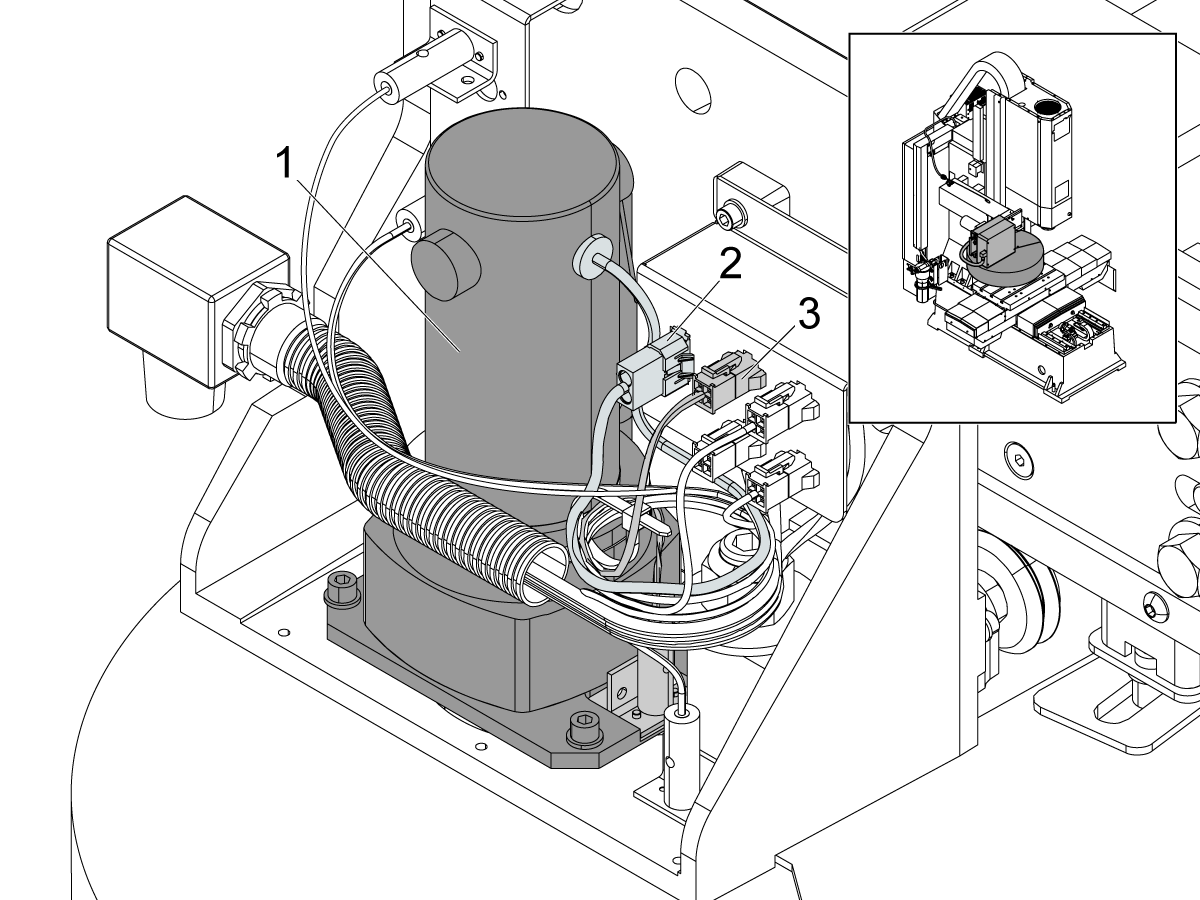
This procedure tells you how to replace the carousel motor on a 20- or 32-pocket umbrella tool changer, and a GR machine with a 10-pocket umbrella tool changer.

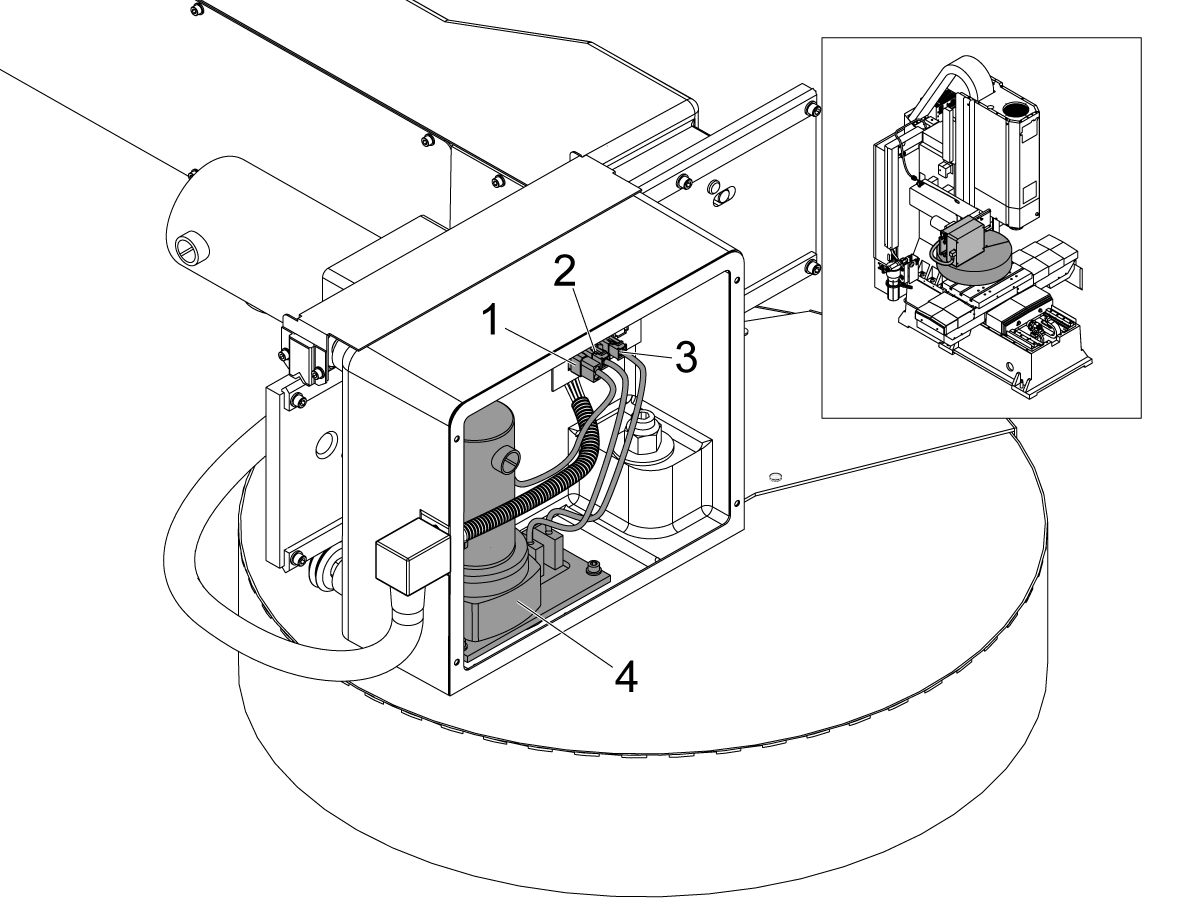
  1. carousel motor power cable
  2. tool-in-position limit switch
  3. tool-1-in-position limit switch
  4. carousel motor

Machine Compatibility

All VMCs

Requirements:

  • VMCs with a 20/32-pocket umbrella tool changer
  • GR machines with a 10-pocket umbrella tool changer, use [KIT] 30-2416

Document Applies to these Parts
This procedure applies to (6) different kits. You only need (1) motor assembly to complete the procedure.

[KIT]

30-2416

QTY: 1

MOTOR, UMBRELLA CAROUSEL 10 POCKET W/ MECH SENSOR (GR & SMM)

[KIT]

93-7000

QTY: 1

MOTOR, UMBRELLA CAROUSEL 16 / 20 POCKET W/ MECH SENSORS (SINGLE PIN DRIVE)

[KIT]

30-0005

QTY: 1

MOTOR, UMBRELLA CAROUSEL 20 POCKET W/ MECH SENSORS(DUAL PIN DRIVE)

[KIT]

93-30-0005A

QTY: 1

MOTOR, UMBRELLA CAROUSEL 20 POCKET W/ PROX SENSORS(DUAL PIN DRIVE)

[KIT]

93-1685

QTY: 1

MOTOR, UMBRELLA CAROUSEL 32 POCKET W/ MECH SENSORS (DUAL PIN DRIVE)

[KIT]

30-0016

QTY: 1

MOTOR, 50T UMBRELLA CAROUSEL 20 POCKET W/ MECH SENSORS

Umbrella Tool Changer - Pocket Carousel - Motor - Replacement

1

Push [POWER OFF]. Set the main circuit breaker to the OFF position.

Lock the main circuit breaker. Use an approved lock with an approved safety tag.

2

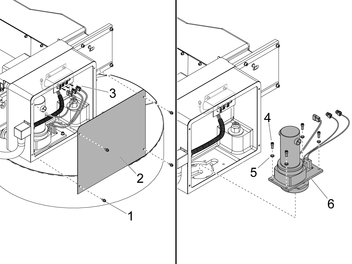
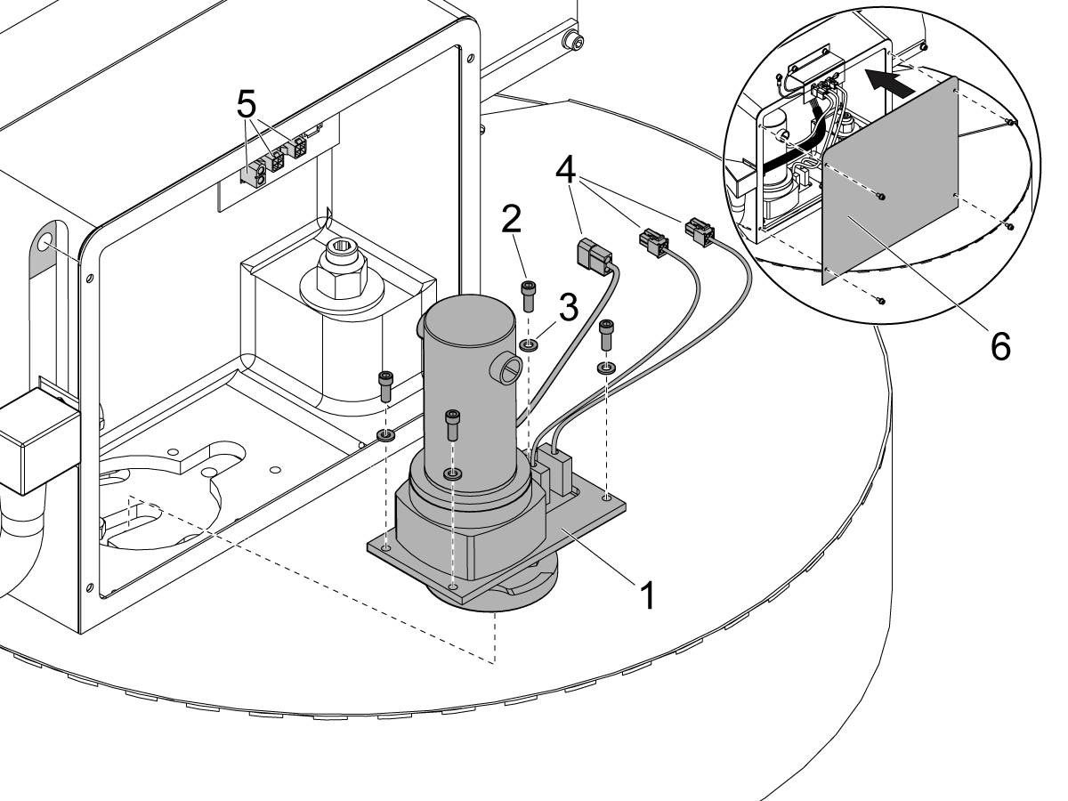
Remove the (4) screws [1] that attach the cover panel [2] to the tool changer carriage. Remove the cover panel [2].

 Note: 10-pocket carousel motor covers have the screws on the back of the tool changer carriage.

Disconnect the carousel motor cable, the tool-in-position cable, and the tool-1-in-position cable [3] from the electrical bracket.

Remove the (4) screws [4] and (4) washers [5] that attach the carousel motor assembly [6] to the bottom of the tool changer carriage. Remove the carousel motor [6].

3

Attach the new carousel motor assembly [1] to the bottom of the tool changer carriage. Use the (4) screws [2] and (4) washers [3].

Connect the carousel motor cable, the tool-in-position cable, and the tool-1-in-position cable [4] to the electrical bracket [5].

Install the cover panel [6] to the tool changer carriage.

Unlock the main circuit breaker. Set the main circuit breaker to the ON position.

Push [POWER ON]. Push [POWER UP/RESTART].

Make sure the umbrella tool changer rotates.

3.8 Umbrella Tool Changer - 10-Pocket Carousel - Motor Replacement

Recently Updated

Umbrella Tool Changer - 10-Pocket Carousel - Motor Replacement


AD0301

Revision A 08/2025

Introduction

This procedure tells you how to replace the carousel motor on a 10-pocket umbrella tool changer.

  1. carousel motor
  2. carousel motor power cable
  3. tool changer proximity sensor

Machine Compatibility

  • VMCs with a 10-pocket umbrella tool changer

 Note: SMM and GR machines with a 10-pocket umbrella tool changer use the same kit ([KIT] 30-2416). To replace a 10-pocket carousel motor on a GR machine, refer to Umbrella Tool Changer - 20/32-Pocket Carousel - Motor - Replacement.

Document Applies to these Parts

This procedure applies to (4) different kits. You only need (1) motor assembly to complete the procedure.

[KIT]

30-2416

QTY: 1

MOTOR, UMBRELLA CAROUSEL 10 POCKET W/ MECH SENSOR (GR & SMM)

[KIT]

93-1696

QTY: 1

MOTOR, UMBRELLA CAROUSEL 10 POCKET W/ PROX SENSOR (SMM)

[KIT]

93-30-1679A

QTY: 1

MOTOR, UMBRELLA CAROUSEL 10 POCKET W/ PROX SENSOR (MM)

[KIT]

93-1681

QTY: 1

MOTOR, UMBRELLA CAROUSEL 10 POCKET W/ MECH SENSOR (MM)

Umbrella Tool Changer - 10-Pocket Carousel - Motor - Replacement

1

Push [POWER OFF]. Set the main circuit breaker to the OFF position.

Lock the main circuit breaker. Use an approved lock with an approved safety tag.

2

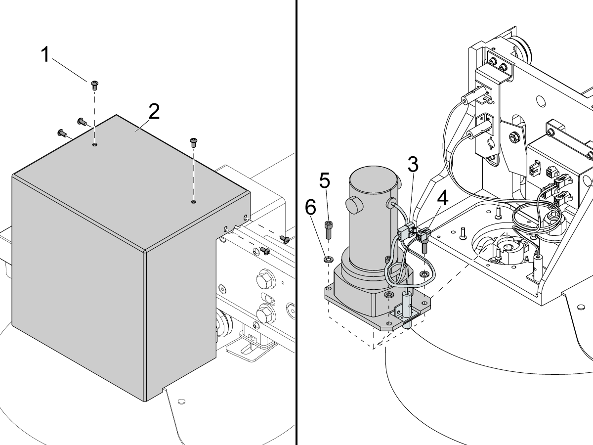
Remove the (8) screws [1] that attach the cover panel [2] to the tool changer carriage. Remove the cover panel [2].

 Note: Covers for the 10-pocket carousel motor have (2) screws on the back of the tool changer carriage.

Disconnect the carousel motor power cable [3]. Disconnect the tool changer proximity sensor [4].

Remove the (4) screws [5] and (4) washers [6] that attach the carousel motor assembly to the bottom of the tool changer carriage. Remove the carousel motor.

3

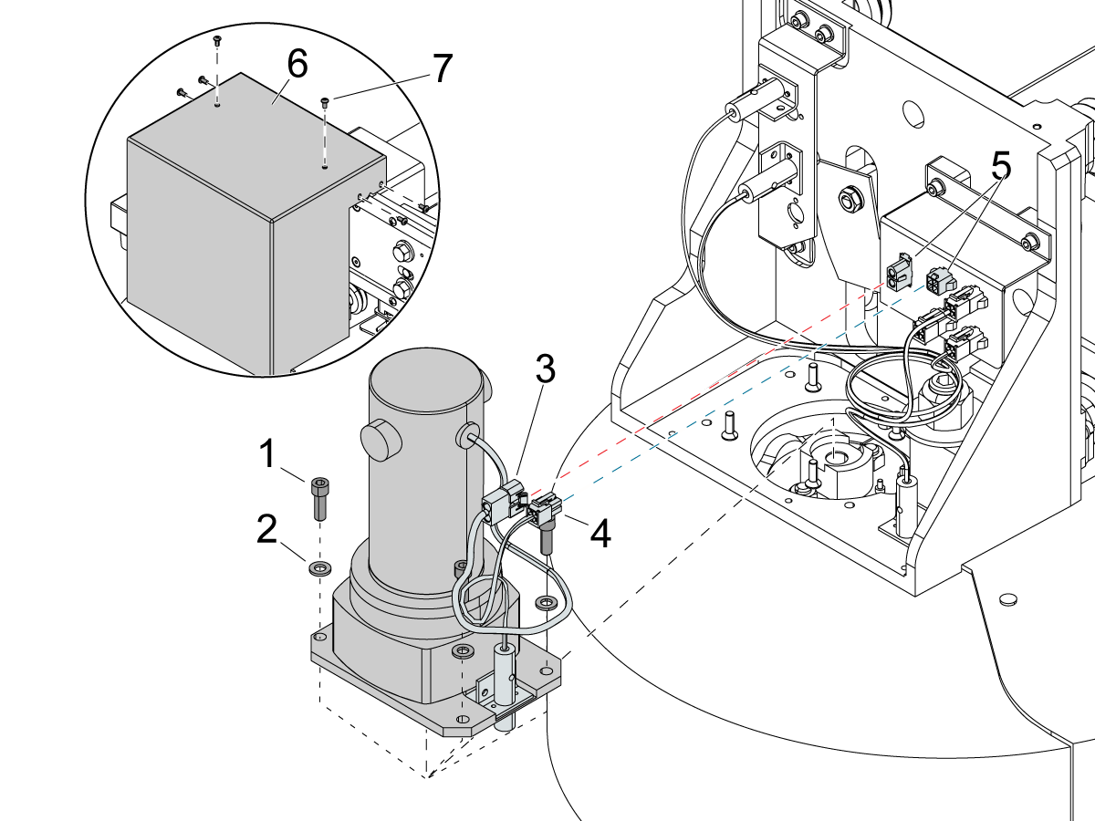
Install the new carousel motor assembly to the bottom of the tool changer carriage. Use the (4) screws [1] and (4) washers [2].

Connect the power cable [3] for the carousel motor and the tool changer proximity sensor [4] to their correct locations [5] on the electrical bracket.

Install the cover panel [6] to the tool changer carriage. Use the (8) screws [7].

Unlock the main circuit breaker. Set the main circuit breaker to the ON position.

Push [POWER ON]. Push [POWER UP/RESTART].

Make sure the umbrella tool changer rotates.

Recently Viewed Items

You Have No Recently Viewed Items Yet

Feedback
Haas Logo

Haas Delivered Price

This price includes shipping cost, export and import duties, insurance, and any other expenses incurred during shipping to a location in France agreed with you as a buyer. No other mandatory costs can be added to the delivery of a Haas CNC Product.

KEEP UP WITH THE LATEST HAAS TIPS AND TECHNOLOGY...

Sign up now!   

HAAS TOOLING ACCEPTS THE FOLLOWING:

  • Service & Support
  • Owners
  • Request Service
  • Operator Manuals
  • Haas Parts
  • Rotary Repair Request
  • Pre-Install Guides
  • Shopping Tools
  • Build & Price a New Haas
  • Available Inventory
  • The Haas Price List
  • CNCA Financing
  • About Haas
  • Accessibility Statement
  • DNSH Statement
  • Export Compliance
  • Careers
  • Certifications & Safety
  • Contact Us
  • History
  • Terms & Conditions
  • Haas Tooling Terms & Conditions
  • Privacy
  • Warranty
  • Haas Community
  • Haas Certification Program
  • Haas Motorsports
  • Gene Haas Foundation
  • Haas Technical Education Community
  • Events
  • Join the Conversation
  • Facebook
  • X
  • Flickr
  • YouTube
  • LinkedIn
  • Instagram
  • TikTok
© 2026 Haas Automation, Inc – CNC Machine Tools
This site is protected by reCAPTCHA and the Google Privacy Policy and Terms of Service apply.

2800 Sturgis Rd., Oxnard, CA 93030
Toll Free: (888) 817-4446 / Fax: 805-278-8554