My Haas Welcome,
!
Haas Tooling MyHaas/HaasConnect Sign In Register Haas Tooling MyHaas/HaasConnect Sign Out Welcome, My Machines Latest Activity My Quotes My Account My Users Sign Out
Find Your Distributor
  1. Select Language
    1. English
    2. Deutsch
    3. Español - ES
    4. Español - MX
    5. Français
    6. Italiano
    7. Português
    8. Český
    9. Dansk
    10. Nederlands
    11. Magyar
    12. Polski
    13. Svenska
    14. Türkçe
    15. 中文
    16. Suomi
    17. Norsk
    18. الإنجليزية
    19. български
    20. Hrvatski
    21. Ελληνικά
    22. Română
    23. Slovenský
    24. Slovenščina
    25. 한국어
    26. 日本語
    27. Українська
  • machines Main Menu
    • Vertical Mills
      Vertical Mills
      Vertical Mills View All
      • Vertical Mills
      • VF Series
      • Universal Machines
      • VR Series
      • VP-5 Prismatic
      • Pallet-Changing VMCs
      • Mini Mills
      • Mold Machines
      • High-Speed Drill Centers
      • Drill/Tap/ Mill Series
      • Toolroom Mills
      • Pocket Mill
      • Compact Mills
      • Gantry Series
      • SR Sheet Routers
      • Extra-Large VMC
      • Double-Column Mills
      • 3+2 Positioning Machines
    • Multi-Axis Solutions
      Multi-Axis Solutions
      Multi-Axis Solutions View All
      • Multi-Axis Solutions
      • Y-Axis Lathes
      • 5-Axis Mills
    • Lathes
      Lathes
      Lathes View All
      • Lathes
      • ST Series
      • Dual-Spindle
      • Box Way Series
      • Toolroom Lathes
      • Chucker Lathe
      • Pocket Lathe
      • Haas Bar Feeders
    • Horizontal Mills
      Horizontal Mills
      Horizontal Mills View All
      • Horizontal Mills
      • 50-Taper
      • 40-Taper
    • Rotaries & Indexers
      Rotaries & Indexers
      Rotaries & Indexers View All
      • Rotaries & Indexers
      • Rotary Tables
      • Indexers
      • 5-Axis Rotaries
      • Extra-Large Rotaries
    • Special Series
      Special Series
      Special Series View All
      • Special Series
      • EU_Series_Redirect
    • Automation Systems
      Automation Systems
      Automation Systems View All
      • Automation Systems
      • Mill Automation
      • Lathe Automation
      • Automatic Parts Loaders
      • Automation Models
    • Desktop Machines
      Desktop Machines
      Desktop Machines View All
      • Desktop Machines
      • Desktop Mill
      • Desktop Lathe
      • Control Simulator, Standard
      • Control Simulator, Premium
    • Shop Equipment
      Shop Equipment
      Shop Equipment View All
      • Shop Equipment
      • Knee Mill
      • Haas Manual Lathes
      • Haas Saws
    • Fabrication Machines
      Fabrication Machines
      Fabrication Machines View All
      • Fabrication Machines
      • Laser Cutting Machines
      • CNC Press Brakes
    • QUICK LINKS Special Series  Special Series 
      EU SERIES EU SERIES BUILD & PRICE | PRICE LIST BUILD & PRICE | PRICE LIST In-Stock Machines In-Stock Machines WHAT’S NEW WHAT’S NEW YOUR FIRST CNC YOUR FIRST CNC
      SHOPPING TOOLS
      • Build & Price a Haas
      • Price List
      • Available Inventory
      • CNCA Financing
      WANT TO TALK TO SOMEONE?

      A Haas Factory Outlet (HFO) can answer your questions, and walk you through your best options.

      CONTACT YOUR DISTRIBUTOR >
  • Options Main Menu
    • The Haas Control Value Option Packages
      Value Option Packages
      Value Option Packages View All
      • Value Option Packages
    • Product Image Spindles
      Spindles
      Spindles View All
      • Spindles
    • Product Image Tool Changers
      Tool Changers
      Tool Changers View All
      • Tool Changers
    • Product Image 4th- | 5th-Axis
      4th- | 5th-Axis
      4th- | 5th-Axis View All
      • 4th- | 5th-Axis
    • Product Image Turrets & Live Tooling
      Turrets & Live Tooling
      Turrets & Live Tooling View All
      • Turrets & Live Tooling
    • Product Image Probing
      Probing
      Probing View All
      • Probing
    • Haas Chip & Coolant Management Chip & Coolant Management
      Chip & Coolant Management
      Chip & Coolant Management View All
      • Chip & Coolant Management
    • The Haas Control The Haas Control
      The Haas Control
      The Haas Control View All
      • The Haas Control
    • Product Image Product Options
      Product Options
      Product Options View All
      • Product Options
    • Product Image Tooling & Fixturing
      Tooling & Fixturing
      Tooling & Fixturing View All
      • Tooling & Fixturing
    • Product Image Workholding
      Workholding
      Workholding View All
      • Workholding
    • Product Image 5-Axis Solutions
      5-Axis Solutions
      5-Axis Solutions View All
      • 5-Axis Solutions
      • 5 Easy Steps to 5-Axis
    • QUICK LINKS Special Series  Special Series 
      EU SERIES EU SERIES BUILD & PRICE | PRICE LIST BUILD & PRICE | PRICE LIST In-Stock Machines In-Stock Machines WHAT’S NEW WHAT’S NEW YOUR FIRST CNC YOUR FIRST CNC
      SHOPPING TOOLS
      • Build & Price a Haas
      • Price List
      • Available Inventory
      • CNCA Financing
      WANT TO TALK TO SOMEONE?

      A Haas Factory Outlet (HFO) can answer your questions, and walk you through your best options.

      CONTACT YOUR DISTRIBUTOR >
  • Why Haas Main Menu
      Discover the Haas Difference
    • Why Haas
    • MyHaas
    • Education Community
    • Industry 4.0
    • Haas Certification
    • Customer Testimonials
  • Service Main Menu
      Welcome to Haas Service
      SERVICE HOME Operator’s Manuals How-To Procedures Troubleshooting Guides Preventive Maintenance Haas Parts Haas Tooling Videos
  • Videos Main Menu
  • Main Menu
    • View All
    • View All
    • View All
    • View All
      • HTEC Curriculum Support
      • Haas Value Option Packages (VOP) Journey
    • View All
      • Haas 10 kg Cobot Package
      • Cobot Kits
      • DC-1 Drill Center
      • CNC Sales News
      • Do More With Your Haas
    • View All
    • View All
      • contact-us-test
      • 4 - AUTOMATION SYSTEMS
      • Carousel-V2
      • expert test
      • Demo_Day_Trident-test
      • Link Test
      • image-sale-tag-test
      • article-list-test
      • Haas 25 kg Robot Package
      • test-algolia-page
    • View All
    • View All
    • View All
    • View All
      • calc-test
    • View All
    • QUICK LINKS Special Series  Special Series 
      EU SERIES EU SERIES BUILD & PRICE | PRICE LIST BUILD & PRICE | PRICE LIST In-Stock Machines In-Stock Machines WHAT’S NEW WHAT’S NEW YOUR FIRST CNC YOUR FIRST CNC
      SHOPPING TOOLS
      • Build & Price a Haas
      • Price List
      • Available Inventory
      • CNCA Financing
      WANT TO TALK TO SOMEONE?

      A Haas Factory Outlet (HFO) can answer your questions, and walk you through your best options.

      CONTACT YOUR DISTRIBUTOR >
  • Haas Tooling Main Menu
  • Haas Service Parts Main Menu

My Haas Welcome,
!
Haas Tooling MyHaas/HaasConnect Sign In Register Haas Tooling MyHaas/HaasConnect Sign Out Welcome, My Machines Latest Activity My Quotes My Account My Users Sign Out
Find Your Distributor
  1. Select Language
    1. English
    2. Deutsch
    3. Español - ES
    4. Español - MX
    5. Français
    6. Italiano
    7. Português
    8. Český
    9. Dansk
    10. Nederlands
    11. Magyar
    12. Polski
    13. Svenska
    14. Türkçe
    15. 中文
    16. Suomi
    17. Norsk
    18. الإنجليزية
    19. български
    20. Hrvatski
    21. Ελληνικά
    22. Română
    23. Slovenský
    24. Slovenščina
    25. 한국어
    26. 日本語
    27. Українська
×

Search Results

Web Pages

Images

    • <
    • 1
    • >

9 - Tool Changer - Troubleshooting Guides

Recently Viewed Items

You Have No Recently Viewed Items Yet

Mill Tool Changer - Service Manual


  • 0 - Mill Tool Changer - Table of Contents
  • 1 - Mill Tool Changer - Introduction
  • 2 - Mill Tool Changer - Overviews
  • 3 - Umbrella Tool Changer - Service Replacements
  • 4 - Umbrella Tool Changer - Alignment
  • 5 - Side Mount Tool Changer - Service Replacements
  • 6 - Side Mount Tool Changer - Alignment
  • 7 - Double Arm and Cambox - Service Replacements
  • 8 - Track Tool Changer - Service Replacements
  • 9 - Tool Changer - Troubleshooting Guides
  • 10 - Side-mount Tool Changer - Maintenance

Go To :

  • 9.1 Umbrella Tool Changer - TSG
  • 9.2 SMTC - Double Arm / Cambox - TSG
  • 9.3 SMTC - Carousel and Pocket - TSG
  • 9.4 Track Tool Changer - TSG

9.1 Umbrella Tool Changer - Troubleshooting Guide

Recently Updated

Umbrella Tool Changer - Troubleshooting Guide


TG0155

Revision A - 08/2025

Introduction

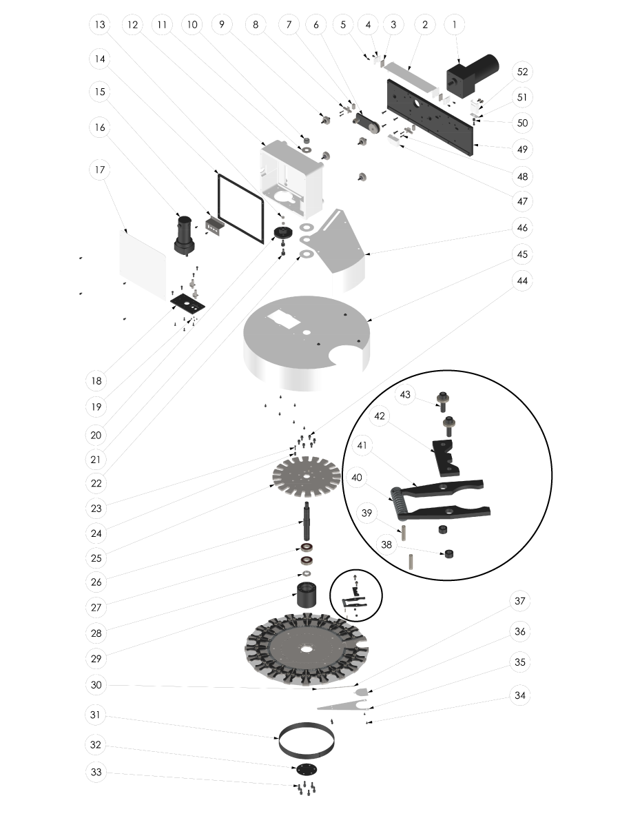
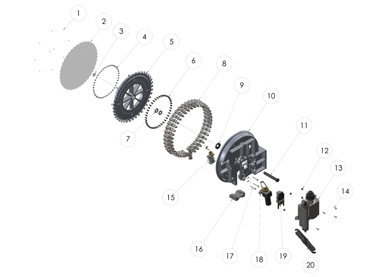
EXPLODED VIEW:

  1. SHUTTLE MOTOR
  2. V-TRACK COVER
  3. WIPER
  4. WIPER RETAINER
  5. SHCS 10-32 X 3/8
  6. SLIP CLUTCH ARM
  7. MOUNTING BLOCK
  8. PROXIMITY SENSOR
  9. SHUTTLE ROLLER
  10. NUT 3/4-10 NYLON LOCK
  11. WASHER 3/4 FLAT
  12. TOOL CARRIAGE
  13. NUT 3/8-24 HEX
  14. GASKET TOOL CARRIAGE
  15. CONNECTOR BRACKET
  16. TURRET MOTOR
  17. TOOL CARRIAGE COVER
  18. MOTOR MOUNTING PLATE
  19. SHCS M3 X 5
  20. DRIVER GENEVA 2 PIN
  21. CAM FOLLOWER 3/4 HEX
  22. SPACER RING
  23. BHCS 10-32 X 1
  24. TOOL #1 STANDOFF
  25. GENEVA STAR
  26. VERTICAL AXLE
  27. BEARING
  28. BEARING LOCKNUT
  29. BEARING HOUSING
  30. DOOR SPRING
  31. NUMBER RING
  32. TOOL CHANGER CAP
  33. SHCS 5/16-18 X 1
  34. FHCS 10-32 X 3/8
  35. SLIDING PANEL COVER
  36. SLIDING PANEL DOOR
  37. RIVET 3/32 X .200 X .160 HEAD DIA
  38. EXTRACTOR BUSHING
  39. ROLL PIN 3/16 X 7/8
  40. EXTRACTOR COMPRESSION SPRING
  41. EXTRACTOR
  42. ALIGNMENT KEY
  43. SHCS 1/4-20 X 7/8
  44. SHCS 5/16-18 X 3/4
  45. TOOL CHANGER COVER
  46. TRAP DOOR
  47. SWITCH COVER
  48. SHCS 8-32 X 7/8
  49. HOLDING PLATE
  50. LOCATING PIN
  51. DOOR OPENER BRACKET LOWER
  52. DOOR OPENER BRACKET UPPER


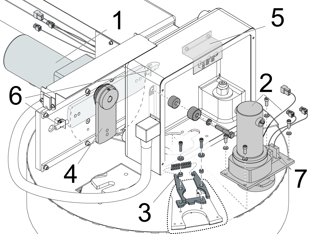
  1. Shuttle motor: DC motor that drives the slip clutch arm assembly to move the shuttle in and out of the spindle.
  2. Carousel motor: DC motor that rotates the carousel.
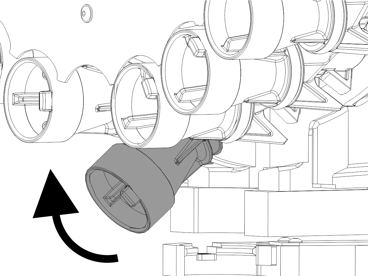
  3. Tool Changer pocket assembly: Holds the tools in the carousel, it consists of two extractor fingers, spring, locating tool key.
  4. Slip clutch arm: Mechanism that couples the shuttle motor to the carriage casting, it will slip if there is a crash to prevent damage to tool changer.
  5. Carousel motor connector bracket: The motor and sensors will connect to this connector bracket.
  6. Shuttle in and out sensors: These sensors let the control know the shuttle position.
  7. Tool #1 and tool mark sensors: These sensors let the control know the carousel position.

Symptom Table

Symptom Possible Cause Corrective Action

Alarm 113 SHUTTLE IN FAULT


Alarm 114 SHUTTLE OUT FAULT

Alarm 125 SHUTTLE FAULT

Alarm 856 ATC SHUTTLE DRIVE TRAIN FAILURE

Alarm 859 ATC SHUTTLE MOTOR ELECTRICAL FAULT

Alarm 2066 TOOL CHANGER HOME POSITION FAULT


Chips interfere with the umbrella tool changer proximity sensors or the movement of the shuttle. Check the system for chips. Refer to the Rail Guides and Proximity Sensors section.
The motor does not receive power. Check the voltage to the motor.  Refer to the Carousel and Shuttle Motor section.
Check resistance in the motor. Refer to the Carousel and Shuttle Motor section.
Check the motor brushes. Refer to the Carousel and Shuttle Motor section.
The slip clutch arm is loose or damaged. Inspect the slip clutch arm.  Refer to the Slip Clutch Arm section
The spindle orientation is incorrect. Set the correct spindle orientation.
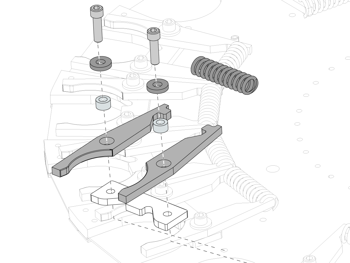
The extractor fingers or springs are damaged or worn. Rebuild the tool pockets.
The carousel plate is bent. Find the cause of the bent carousel plate.
Damaged cable or loose cable connection. (Especially if problem is intermittent or during movement of shuttle)
Inspect pins and cable for condition.
One of the tool changer relays is faulty. Test the tool changer relays.
Alarm 143 SPINDLE ROTATED DURING A TOOL CHANGE Incorrect alignment of the carousel plate to the spindle is causing the spindle to turn as it goes into the tool holder. Check the tool changer alignment to the spindle.
The spindle orientation is incorrect. Set the correct spindle orientation.
The orientation is weak due to low voltage or loose motor power wires. Check for loose wires at the spindle motor and amplifier terminals.  Check incoming voltage.

Alarm 115 CAROUSEL POSITION FAULT


Alarm 127 NO TURRET MARK

Alarm 854 ATC CAROUSEL DRIVE TRAIN FAILURE

Alarm 942 CAROUSEL POSITION TIME OUT


Chips interfere with the umbrella tool changer proximity sensors or movement of the shuttle. Check the system for chips.
The proximity sensor is faulty or not recieveing power Check the operation of the proximity sensor
One of the tool changer relays is faulty. (non-servo motor tool changers only) Test the tool changer relays.
The motor does not receive power. Check resistance in the motor.
Check the motor brushes.
Alarm 115 CAROUSEL POSITION FAULT, during Power-up. There is a software error (NGC only). Set setting 81 TOOL AT POWER UP to 0, as a temporary work around. Check NGC software release notes for when the error was corrected.


Note: Only a Certified Service Technician can upgrade the machine software.

Tools fall or drop from the tool changer. The extractor fingers or springs are damaged or worn. Rebuild the tool pockets.
The pull studs are incorrect. Check the tool specifications.
The tool is too heavy or too long.
The Umbrella Tool Changer Carousel Plate is Loose. The lock nut on the shaft axle is loose. Check the lock nut on the shaft axle, bearing housing bolts and the 6 screws that hold the carousel plate.
The bolts at the bearing housing are loose.
Mounting hardware in the tool changer assembly is loose.
Tool changes are noisy. The plastic riders on the carousel trap door are damaged or missing. Inspect the carousel trap door.
The guide pin on the carousel trap door is damaged.
The Tool changer is not aligned to the spindle.

Use this procedure to align the Umbrella Tool Changer to the Spindle.

Procedure: Umbrella Tool Changer to Spindle Alignment

The Geneva driver or the Geneva star is damaged. Examine the geneva driver and the geneva star for damage.  Use this procedure:

Carousel Plate Replacement - Umbrella Tool Changer

The shuttle roller bolts are not adjusted correctly.

Use this procedure to adjust or replace the shuttle rollers.

Procedure: Shuttle Roller Replacement and Adjustment

The sliding panels do not fully retract.

The sliding panels do not move smoothly. The tools make scores or scratches on the inner surface of the carousel. Clean the slider and spring assembly.

Use the correct procedure for slider and spring removal. Refer to Umbrella Tool Changer - Pocket - Replacement.

The Umbrella Tool Changer Trap Door Does Not Open The trap door pivot point is not greased. Grease the trap door pivot point.
There are chips between the trap door and the carousel. Inspect the carousel trap door.
The plastic trap door riders are worn.
CM-1 36 Pocket Tool Changer Only: Misloading of the tools. The tool changer's door spring is too strong.  Replace with weaker door spring P/N 93-3750. Refer to CM-1 36 Pocket Tool Changer - Door Spring Replacement - AD0678 for more information. 

For Umbrella Tool Changers built before 02/2022

Alarm 856 ATC Shuttle Drive Train Failure

Alarm 859 ATC Shuttle Motor Electrical Fault

Alarm 9809 Tool Changer Bus Short Circuit

Coolant getting into the shuttle motor windings through the brush caps.

Clean out brush caps/brushes and attach vinyl caps with sealant, refer to the Shuttle Motor Coolant Intrusion section below for more info.

Note: Shuttle motors on umbrella tool changers built February 2022 and later are dipped and sealed at the factory and will not require the vinyl caps.

Shuttle Motor Coolant Intrusion

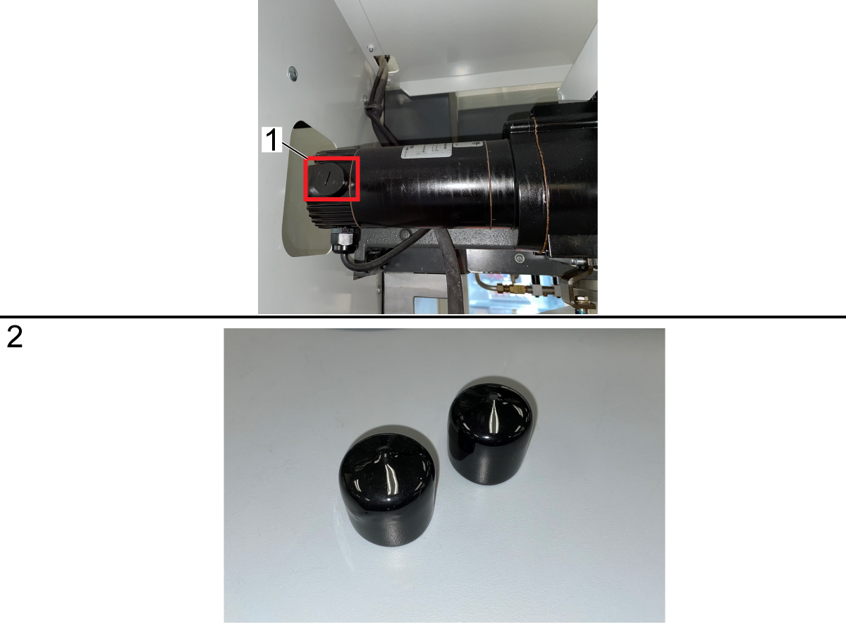
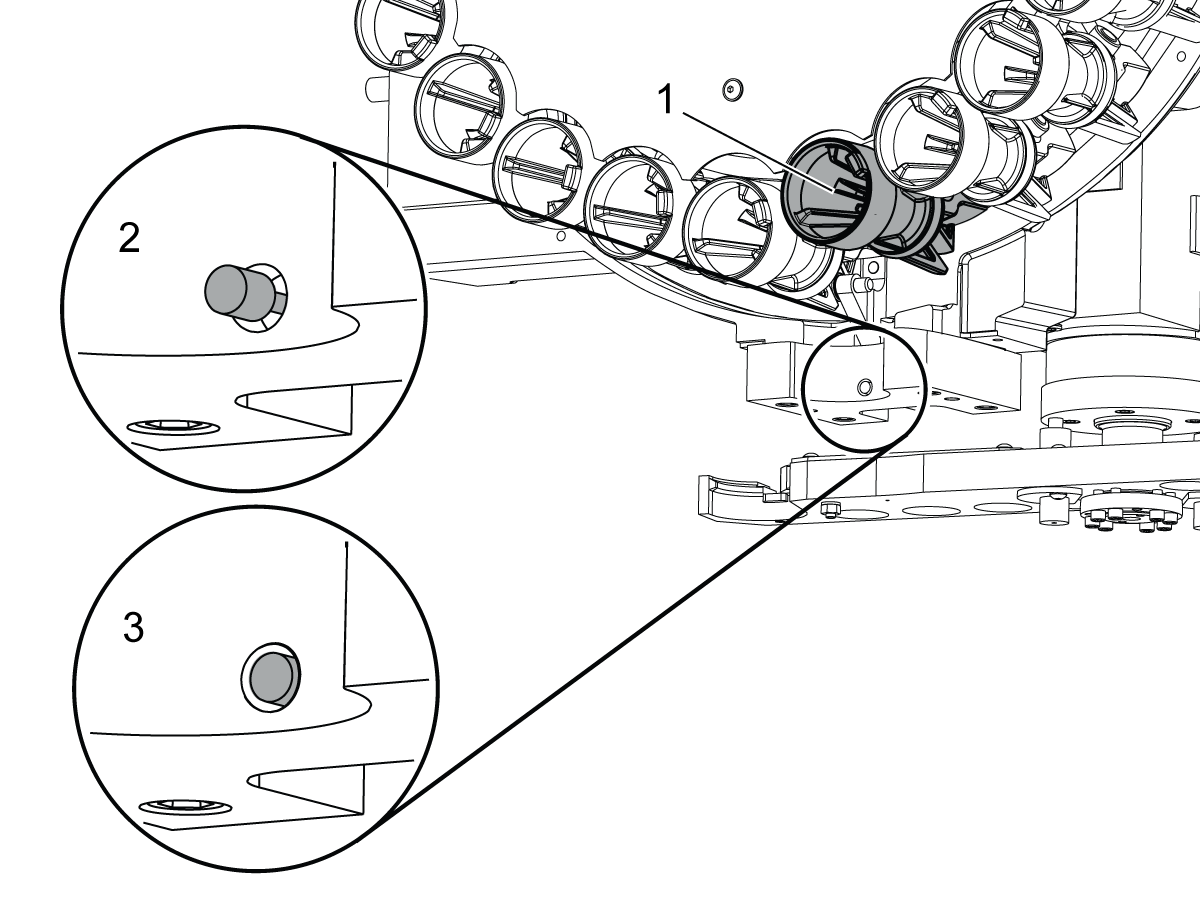
1. Remove the brush caps [1] from both sides of the motor

2. Inspect the brushes for coolant intrusion and clean and reinstall the brushes and their brush caps.

3. Order two (2) vinyl caps [2] for the shuttle motor

  • PN 59-2011 for 32-1875: MTR ASSY CAROUSEL/SHUTTLE/APC
  • PN 59-0297 for CM-1 tool changers

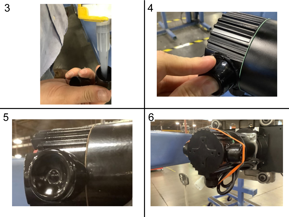
4. Fill the vinyl caps about a 1/4 of the way with RTV Silicone [3]

5. Push the vinyl caps onto the brush caps and rotate them clockwise and counterclockwise for an even seal [4]

6. A good seal could be seen in [5]

7. Put a rubber band around both caps as shown in [6] and leave them on for at least 4 hours to allow the vinyl caps seal to cure.

Note: Shuttle motors on umbrella tool changers built February 2022 and later are dipped and sealed at the factory and will not require the vinyl caps.

Rail Guides and Proximity Sensors

Corrective Action:

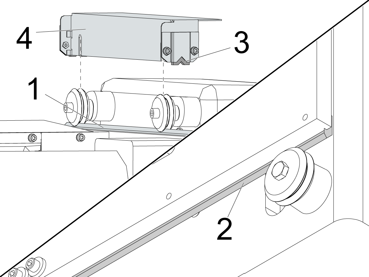
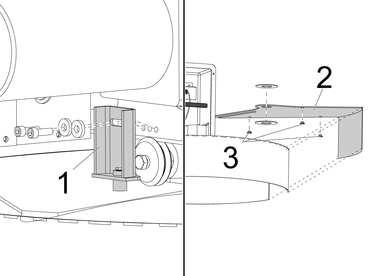
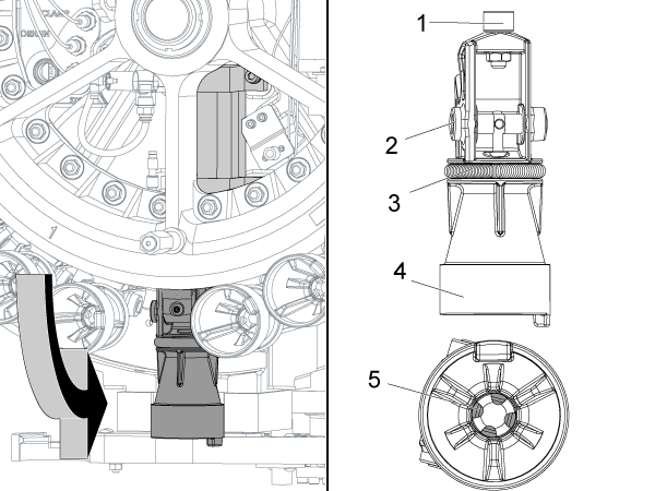
Check the top [1] and bottom [2] V-rails, and the wheels for chips. Check for damaged or worn wipers [3]. Some machines do not have a wiper bracket [4].

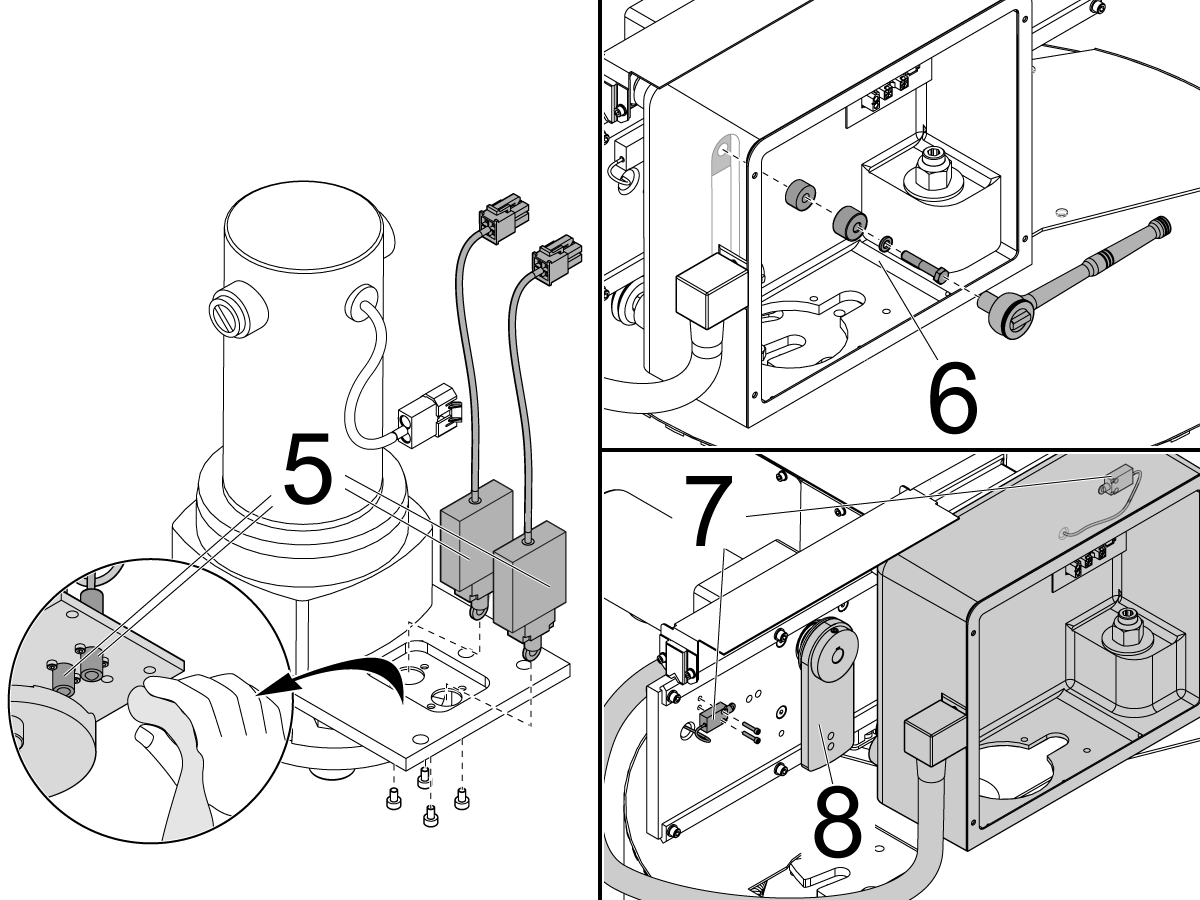
Remove any chips that prevent correct sensor operation. Remove the carousel motor from the carriage assembly. Remove the sensors [5] on both sides of the carousel motor plate to clean them.

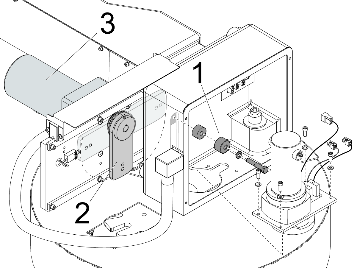
Remove the cam follower assembly [6] and lower the slip clutch arm [8] to move the carriage assembly and access the sensors [7] behind the carriage assembly.

Older machine models use roller switches [5] in place of the proximity sensors. The plunger and roller must operate smoothly without sticking. If the switches or sensors are clean, but do not operate correctly, go to Mechanical Limit Switch - Troubleshooting Guide or Proximity Sensor - Troubleshooting Guide to troubleshoot them.

Carousel and Shuttle Motor

Corrective Action:

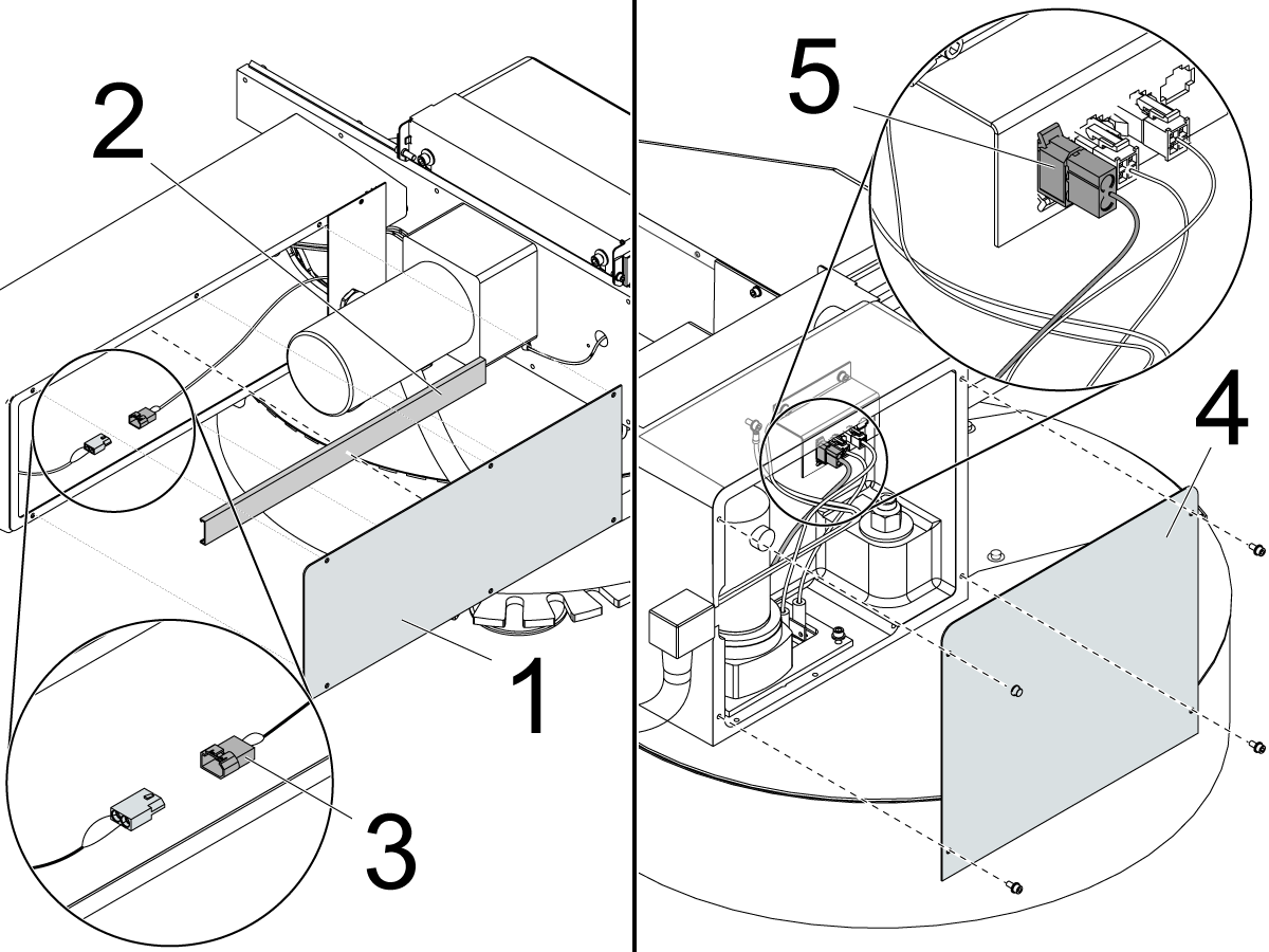
How to access the shuttle motor to troubleshoot alarms 113, 114, 125, 856, 859, and 2066: Remove the support arm cover [1] and cable channel cover [2]. Measure the voltage to the power cable.

How to access the carousel motor to troubleshoot alarms 115, 127, and 854: Remove the cover [4] to the carriage. Measure the voltage to the power cable [5] on the connector bracket.

Measure the voltage:

Measure for DC voltage at the connector that goes to the motor from the I/O PCB. Adjust the range to 0.0 and set your multimeter for Min/Max. The power to the motor will only be on for one second before an alarm generates and the power is shut off to the motor. Command a tool change. The reading must be 135-165 VDC, or show a signal change when it is commanded to run. Some multimeters are not fast enough to read the voltage before the alarm occurs. It should still show a signal change or OL before the alarm is generated. If there is no voltage, refer to:

  • Next Generation Control - I/O PCB - Troubleshooting Guide
  • I/O PCB - Troubleshooting Guide (Classic Haas Control)

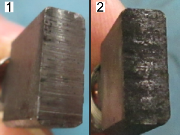
Inspect the brushes.

  1. Normal wear on brush.
  2. Bad wear on brush.

Disconnect the motor from the connector. Measure the resistance from pin to pin. The resistance must be between 5-20 Ohms. Measure the resistance from one of the pins to the motor chassis. The resistance must be greater than 100k Ohms.

If the measurements are low, there is not a good contact between the brushes and the commutator. Vacuum and clean any contamination between the brushes and the commutator. Check for damage or wear. Make sure there are no signs of oil or coolant in the motor. Inspect the area around the DC motor for causes of contamination.

 IMPORTANT: Incorrect installation of the motor brushes can cause malfunction of the motor or noise.

Slip Clutch Arm

Corrective Action:

Inspect the slip clutch arm: Remove and inspect the cam follower assembly [1] for damage and chips. Push the carousel motor housing in the direction of the spindle to get access to the slip clutch arm [2]. Manually turn the slip clutch arm [2] through 180° of movement. It should rotate smoothly, but with heavy resistance. If the arm does not move smoothly, the shuttle motor [3] is faulty.

Spindle Orientation

Corrective Action:

Find the cause of the spindle orientation error.

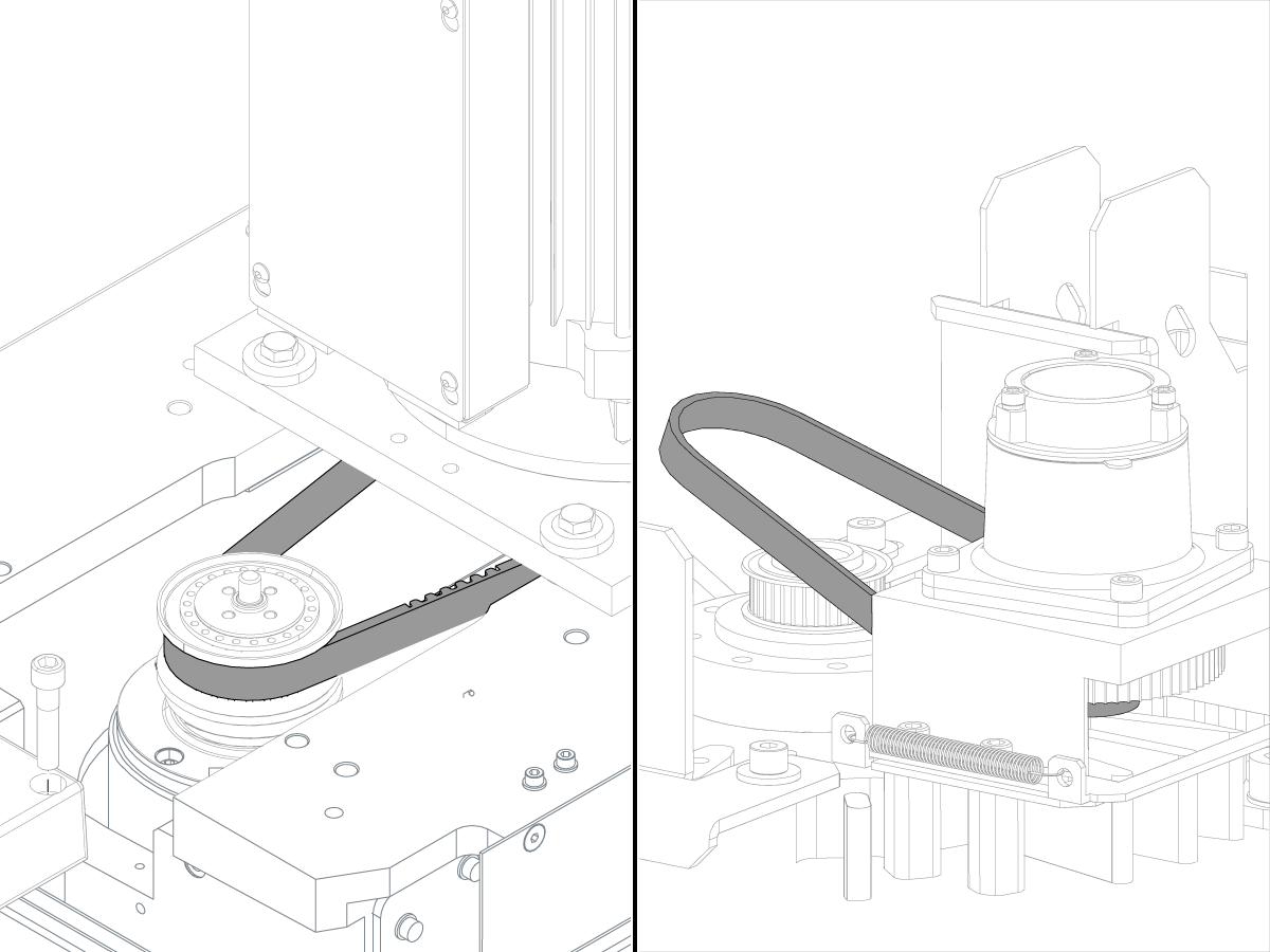
Make sure spindle drive and encoder belts have the correct tension. Make sure the spindle motor pulley and encoder pulley are not worn.

Refer to these procedures

  • CHC - Umbrella Tool Changer - Set Parameter 257 - Spindle Orientation Offset
  • NGC - Umbrella Tool Changer - Spindle Orientation Offset

Tool Changer Relays

Corrective Action:

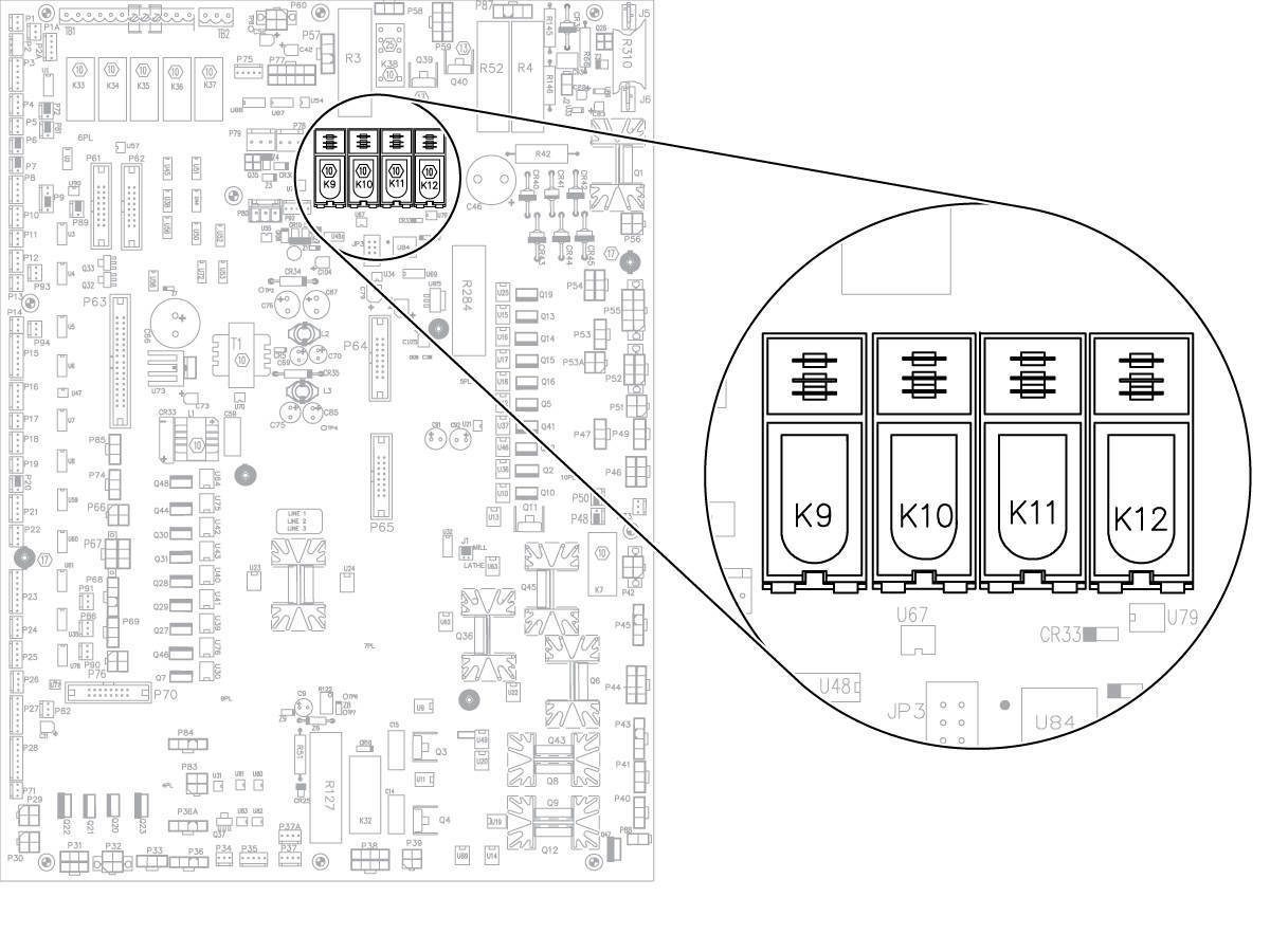
Test the suspected relay: Exchange the relay with another relay. If the alarm changes to a different alarm, the relay is at fault.

For example: If the machine displays Alarm 113, change the K9 relay with the K10 relay. If the alarm changes to Alarm 114, the relay is faulty. If the alarm does not change, proceed to other troubleshooting sections.

Tool Pocket

Corrective Action:

The extractor fingers and spring hold the tool in the tool pocket. Worn or damaged fingers or springs can let the tool fall.

Refer to:

  •  VMC - Umbrella Tool Changer - Pocket - Replacement
  • Video - Umbrella/Carousel Tool Changer Maintenance

Carousel Plate and Tool Release Piston Adjustment

Corrective Action:

If the tool-release piston (TRP) sensors are not adjusted correctly, a tool can get stuck in the spindle taper, or the drawbar might not release a tool. Damage to the umbrella tool changer can occur. Adjust the tool release piston switches correctly. Refer to the TRP - Proximity Sensor - Adjustment procedure.

Go to Umbrella - Tool Changer – Carousel Plate - Replacement for carousel plate replacement instructions.

Carousel Trap Door

Corrective Action:

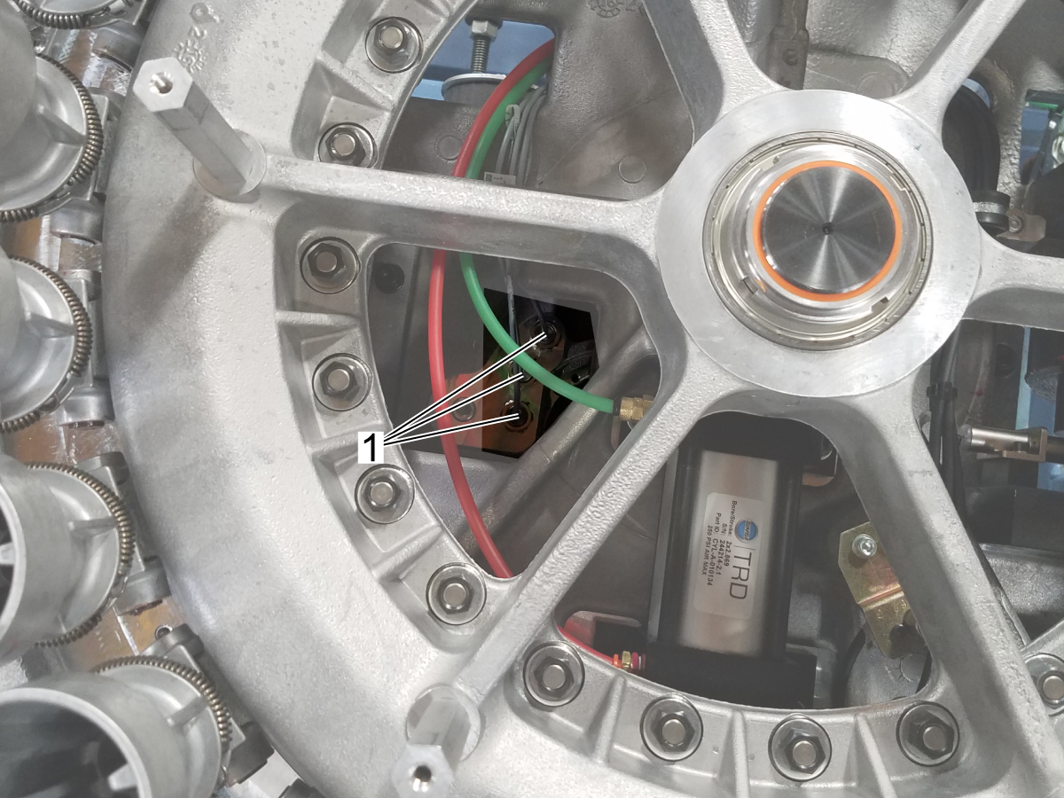
Check for damage to the guide pin [1], trap door [2], and the plastic riders [3].

Refer to the Umbrella Tool Changer - Guide Pin and Trap Door - Replacement procedure.

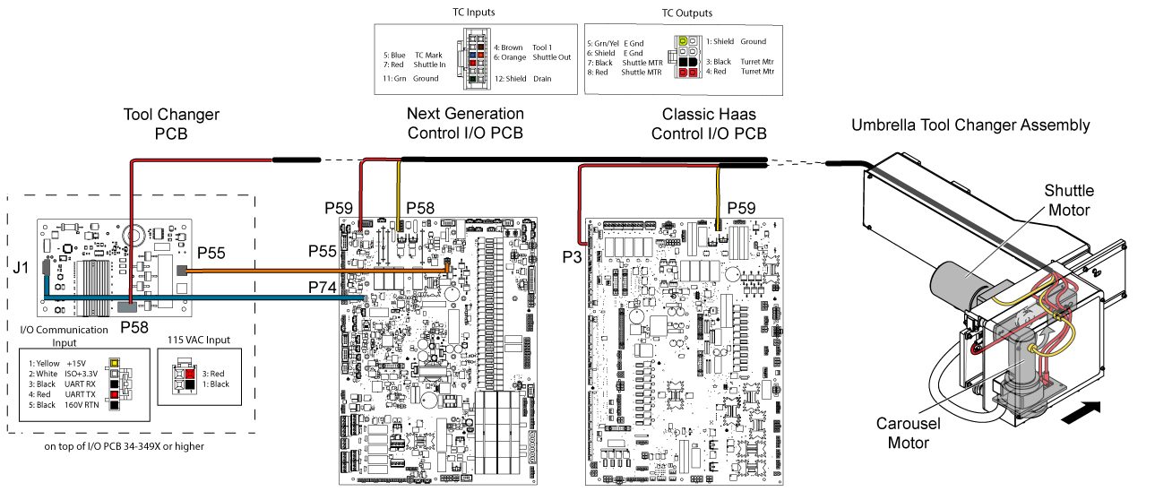
Electrical Diagram

9.2 Side Mount Tool Changer - Double Arm/Cambox - Troubleshooting Guide

Recently Updated

Side Mount Tool Changer (SMTC) - Double Arm/Cambox - Troubleshooting Guide


TG0128

Revision B - 08/2025

Cambox Inspection Report

Download and fillout the Cambox Inspection Report Checklist below before replacing any parts.

Cambox Inspection Report

Introduction

DOUBLE ARM EXPLODED VIEW:

  1. ARM COVER
  2. BHCS 1/4-20 X 1/2 ZINC PLATED
  3. SHCS 3/8-16 X 3/4 ZINC PLATED
  4. DOUBLE ARM HUB
  5. ARM SLIDE
  6. WASHER 5/16 STEEL
  7. PLUNGER
  8. RETURN SPRING
  9. ADJUSTER ROD
  10. SHCS 1/4-20 X 5/8 ZINC PLATED
  11. FHCS 1/4-20 X 5/8 LOCTITE
  12. ARM KEY
  13. DOUBLE ARM
  14. NUT 1/4-20 HEX BLK
  15. SPRING CAP
  16. DOUBLE ARM CLAMP
  17. SHCS 5/16-18 X 2 1/4

CAMBOX EXPLODED VIEW:

  1. OUTPUT SHAFT
  2. HOUSING
  3. HOUSING TOP
  4. SERVO MOTOR
  5. SERVO MOTOR MOUNT
  6.  INPUT WORM SHAFT
  7. WORM GEAR
  8. OIL FILL CAP
  9. STAR GEAR BEARING ASSEMBLY
  10. STAR GEAR
  11. GLOBOIDAL CAM
  12. CHECK VALVE AND MUFFLER
  13. DOUBLE ARM MOUNT

Note: The exploded diagram of the cambox is provided for reference purposes only. The internal components of the cambox are not field-replaceable

  1. Double arm: Moves tools to the carousel and the spindle.
  2. Slide: Pushes against the tool to hold it in place during double arm movement.
  3. Return spring: Pushes the slide against the tool.
  4. Shim washers: Shims adjust the slide for proper clearance. If the slide is adjusted too tightly against the tool, it may not lock during rotation. If adjusted too loosely, tools will rock or fall out during rotation.
  5. Adjuster rod: Locks the slide in place during a tool change.
  6. Jam nut: This nut tightens against the slide to prevent the adjuster rod from rotating loose.
  7. Plunger: Locks the adjuster rod during arm motion. The adjuster rod and slide cannot release the tool when the plunger is in the extended position.

Symptom Table

Symptom Possible Cause Corrective Action

Alarm 11.103 TA-AXIS SERVO ERROR TOO LARGE

Alarm 11.108 TA-AXIS SERVO OVERLOAD

Alarm 11.994 TA (TC ARM) AMPLIFIER OVERLOAD

The cambox is damaged. Test the cambox. Refer to Cambox Test section below on this page. 
Alarm 103 AXIS SERVO ERROR TOO LARGE The cambox drive belt is worn or damaged. Inspect the belt.

Alarm 622 TOOL CHANGER ARM FAULT

Alarm 2066 TOOL CHANGER HOME POSITION FAULT

The tool changer arm is not at the origin position when the machine is powered on, or it was not recovered correctly.

Do a tool change recovery.

Video - Tool Changer Recovery - Side Mount Tool Changer (SMTC)

VMC, HMC - Side-Mount Tool Changer - Manual Recovery

One or more of the proximity sensors or cables on the cambox have a bad connection or is damaged. Rotate the arm in recovery mode and test the sensors.
Pressing [Power-Up/Restart] after updating software generates a 2066 alarm. Do an Option 5 Clean Install.
Alarm 627 ATC ARM MOTION TIMEOUT One or more of the proximity sensors or cables on the cambox have a bad connection or is damaged. Rotate the arm in recovery mode and test the sensors.
The cambox drive belt is worn or damaged. Inspect the belt.

Alarm 628/673 ATC/TA ARM POSITIONING ERROR

Alarm 855 ATC ARM DRIVE-TRAIN FAILURE

The double arm's travel was obstructed.

Check the double arm alignment.

Move the obstructions or set a safe tool change position.

The spindle orientation is incorrect. Find the cause of the spindle orientation error.
The cambox is damaged. Test the cambox. Refer to Cambox Test section below on this page.
The values of Parameters 481 or 487 are incorrect in a machine with a servo-driven side-mount tool changer. Set the correct values for the Parameters 481 and 487 .Parameter 481 is TT Grid Offset. Parameter 487 is TT Tool Change Offset. Set these parameters correctly. Refer to VMC - Servo-Driven Side-Mount Tool Changer - Grid Offset and Tool Changer Offset.
The TRP quick exhaust is not functioning properly If the quick exhaust is not working properly it may cause the tool to drop slightly or be miss positioned during the tool change. Inspect and replace the quick exhaust if needed.
Tools fall out of the spindle side during a tool change. The toolholders or pull studs are incorrect. Check for correct tool specifications.
The tool is too heavy. Check for correct tool weight specifications. Flag large or heavy tools.
The arm or plunger is worn. The double arm cannot correctly engage with the tool. Replace the worn parts in the double arm. 
The spindle orientation is incorrect. Find the cause of the spindle orientation error.
The double arm is bent or damaged.  Find the cause of the double arm bending. Straighten and smooth the double arm or replace it.
The gap between the tool holder and slide is not within specifications. Refer to: Side-Mount Tool Changer - Double Arm - Plunger and Adjuster Assembly - Inspection - Mill
Tools fall out of the arm during rotation. The arm and plunger are worn. The double arm cannot correctly engage with the tool. Replace the worn parts in the double arm.
Tools fall out of carousel tool pockets. The pocket spring or plungers are worn or damaged. Refer to : Side Mount (SMTC) - VF/VM/UMC/EC - Carousel and Pocket - Troubleshooting Guide
The cambox on a DT/DM is unable to rotate by hand . The cambox will not be able to rotate by hand because it will eventually contact the rocker arm and try to unclamp the spindle. DO NOT replace the cambox because you are unable to rotate by hand contact your local Haas Factory Outlet for further assistance. 
EC/VC tool change cycle is very slow. Parameter 223 Tool Changer Air Door Delay Change has a value, this should only have a value if a pnuematic door is present

Update configuration files to the latest, Parameter 223 will be set to zero. This configuration files have been backdated so that all machines will receive this updated value. 

NOTE: Remember to take a back up before loading the latest configuration files.
HSG-N 02-14-2023

Replacement double arm is not the correct length.

The incorrect double arm may have been ordered. Verify the correct part number and supersession has been ordered.

Refer to the Double Arm Replacement Verification Section for futher information on how to verify that the double arm ordered is correct for your machine.
The double arm is the incorrect taper size and type.
The double arm key offset is not correct.
Vertical Cambox's built June 15 2023 and later
Oil is leaking out of the cambox arm shaft.

Note: This does not affect DT/DM/UMC-350 camboxes.
There may be a problem with the exhaust check valve assembly.

Starting in June 2023 a check valve is now included with the cambox exhaust assembly. Verfiy that the check vavle is facing the correct way, reference the Cambox Exhaust Check Valve section below.

HSG-N 07-12-2023

Corrosion inside of cambox. The output shaft seal has gone bad and coolant has gotten into the cambox.
Replace corroded parts inside of cambox. Replace the output shaft seal and check for scoring on the shaft. If there is scoring, replace the output shaft. Refill the cambox with oil. 

SMTC Double Arm Replacement Verification

NOTE: The same verification steps will apply to machined [1] and casted [2] double arm replacements.Some machines may still received machined [1] double arm replacements. Use the image below as reference.

Verify the double arm length

Check that the replacement double arm [2] is the correct length, measure from the center to center of the tool holder flange between the original [1] and replacement double arm [2].

NOTE: The same verification steps will apply to machined [1] and casted [2] double arm replacements.Some machines may still received machined [1] double arm replacements.

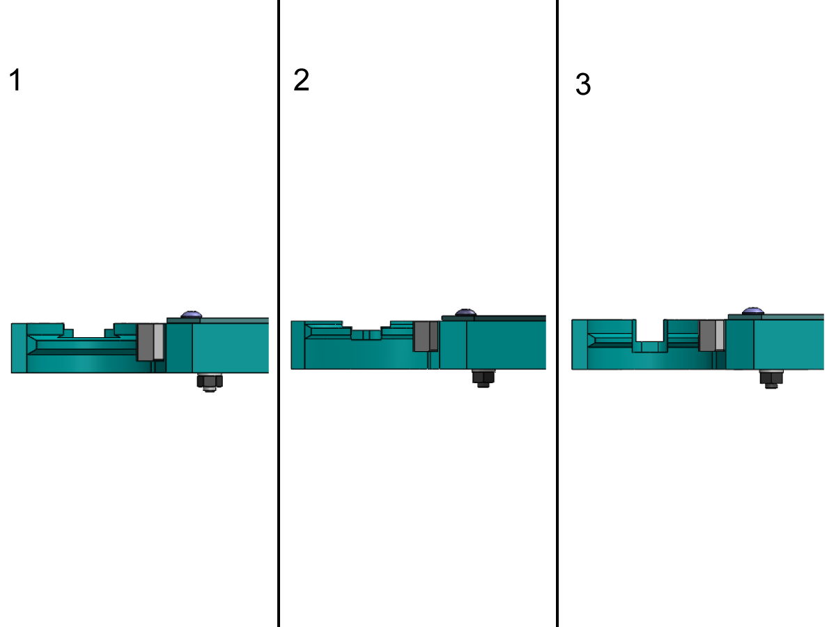
Verify that the double arm is the correct taper size and type

To differentiate between the BT, CT, and HSK verify that the BT V-flange is as shown in image [1] and the CT V-flange is as shown in image [2], and the HSK V-flange is as shown in image [3].

Verify that the double arm has the correct key slot offset

Now the casted double arm will have the key slot machined in a 0 degree angle position [1] or at a 2.5 degree angled position [2], both double arms will use only a straight key instead of an offset key.

HSG - 7/5/2023

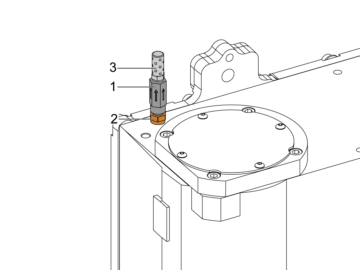
Cambox Exhaust Check Valve

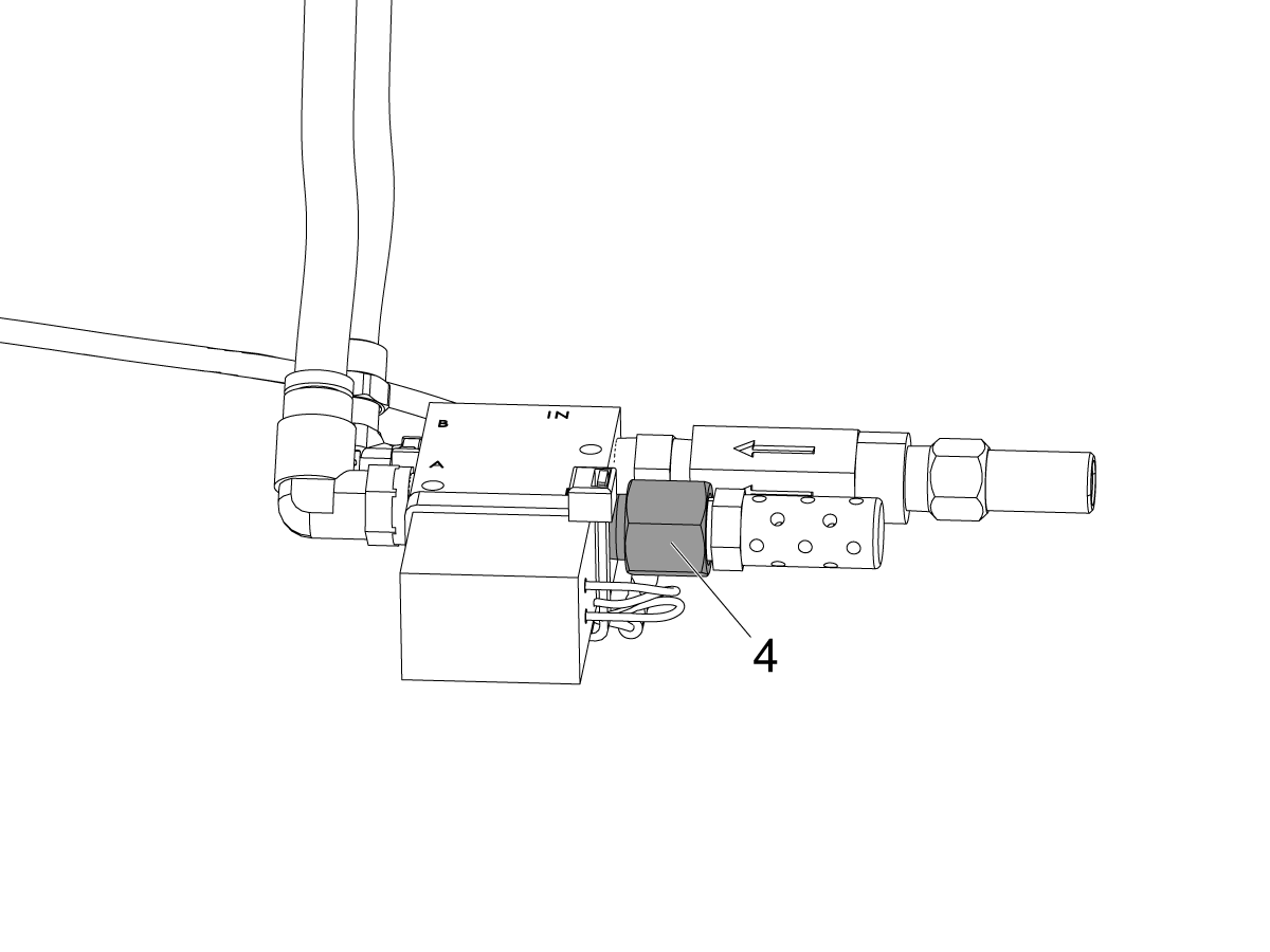
Verify the check valve [1] arrow is facing away from the cambox as shown. 

The check valve (PN 58-2754) [1] should be install between the brass fitting (PN 58-1674) [2] and muffler fitting (PN 58-1865) [3]. 

HSG - 7/12/2023

Cambox Proximity Sensors

Corrective Action:

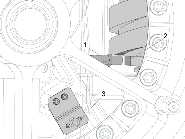
Remove the carousel number plate to get access to the sensors [1]. Go into the manual tool recovery and push ATC FWD to move the arm through a complete cycle. Make sure the LED on the sensor and the diagnostic bit state change at the correct stage of the tool change cycle. See the chart below.

If the sensors fail to change state, refer to the Proximity Sensor - Troubleshooting Guide.

SENSOR Origin Rotation Tool Pick - Up Down / Rotation 180 / Up Tool Exchange Arm Backup (Reverse) Origin
Clamp/unclamp On / 0 On / 0 Off / 1 On /0 Off / 1 On / 0 On / 0
Origin Off / 1 On / 0 On / 0 On / 0 On / 0 On / 0 Off / 1
Motor stop Off / 1 On / 0 Off / 1 Red / 0 On / 1 On / 0 Off / 1

Spindle Orientation

Corrective Action:

Find the cause of the spindle orientation error.

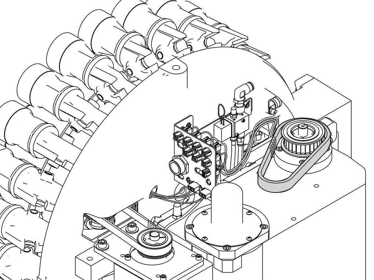
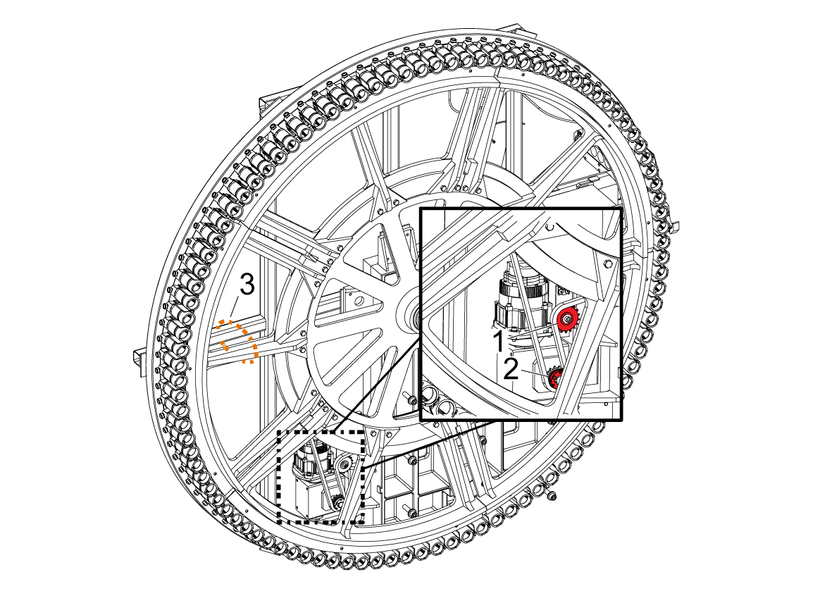
Make sure spindle drive and encoder belts have the correct tension. Make sure the spindle motor pulley [1] and encoder pulley [2] are not worn.

Refer to VMC - Side-Mount Tool Changer - Spindle Orientation Offset - Parameter 257.

Double Arm Alignment

Corrective Action:

Use a straightedge to find out if the arm is bent. If the arm is bent, these are some of the possible causes:


1: The tool release piston (TRP) sensor(s) are not adjusted correctly.

If the TRP sensors are not adjusted correctly, a tool can get stuck in the spindle taper, or the drawbar might not release a tool. Damage to the double arm can occur. Adjust the tool release piston switches correctly. Refer to VMC - 20/30/40-Taper- TRP - Proximity Sensor - Adjustment.

2: The arm crashed into a rotary or a fixture during a tool change.

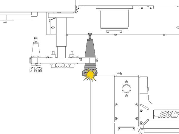
Refer to your operator's manual to set the tool change offset, or alias an M06 command, to move the spindle to a safe height. Move the obstacle on the table to a safe distance away before the tool change. If you install a rotary or trunnion unit, mount it as far to the right as your setup will allow. This gives you more room for safe tool changes.

Go to Episode 21 - How to Command a Safe Tool Change Position to Avoid Fixtures and Rotaries for more information.

3: A failed cambox position cable or sensor may cause the machine to think the arm is at the home position. The Z Axis comes down and bends the arm. Refer to Cambox Proximity Sensors section in this document.

Minor burrs or gouges on the double arm can visually be removed with a small file without needing replacement.

Go to parts.haascnc.com to find the correct double arm for your machine. Follow the replacement instructions that ship with the assembly.

If the double arm is not bent check the double arm alingment. Refer to Side Mount (SMTC) - VMC - Double Arm - Alignment for instructions on how to check the alignment.

Cambox Drive Belt

Corrective Action:

Inspect the belt for damage and replace it if necessary. Refer to VMC - Side-Mount Tool Changer (SMTC) - Carousel Motor - Replacement for how to replace the cambox belt.

Toolholder and Pull Studs

Corrective Action:

Refer to this document for the correct pull stud and tool weight specifications:

  • Toolholder and Pull Stud Information

If you have a very heavy tool, install the Pocket slow down Service Kit (P/N 93-0254). This kit restricts the air exiting the pocket up/down cylinder to slow down the pocket.

Double Arm Plungers

Corrective Action:

Inspect the plunger and adjuster assembly. Refer to Side-Mount Tool Changer - Double Arm - Plunger and Adjuster Assembly - Inspection

Refer to Video - Side Mount Tool Changer (SMTC) Double Arm Maintenance for more information on how to maintain the double arm.

Cambox Test

Cambox Lost Motion Test

Go to Tool changer recovery.

Rotate the double arm to clamp/unclamp position.

  1. Push and pull on the arm. Record the movement.
  2. Pull down and push up on the arm.   Record the movement.

There should be less than 1/4" (6 mm) of lost motion in the rotation or lift of the arm.

Cambox Internal Mechanical Test

Remove the cambox motor and rotate the pulley or coupling [1] to cycle the cambox through a complete tool changer cycle. Listen for any abnormal internal noise when cycling the cambox. Run cambox forward or backwards looking for any particular section of binding. Check oil level while noting the viscosity and coloration of the oil.

Note: Be sure to rotate the cambox to the complete tool changer cycle as some components are only engaged every other tool changer. 

There should not be any binding in the cambox. You should be able to turn the pulley by hand. It will take more effort to turn the pulley when the output shaft is retracting.

Note:  On machine with a servo driven cambox it is necessary to re-set the double arm origin position after reinstalling the servo motor.  Refer to the SMTC - Double Arm - Grid and Tool Change Offset procedure.

Double Arm Tool and Slide Adjustment

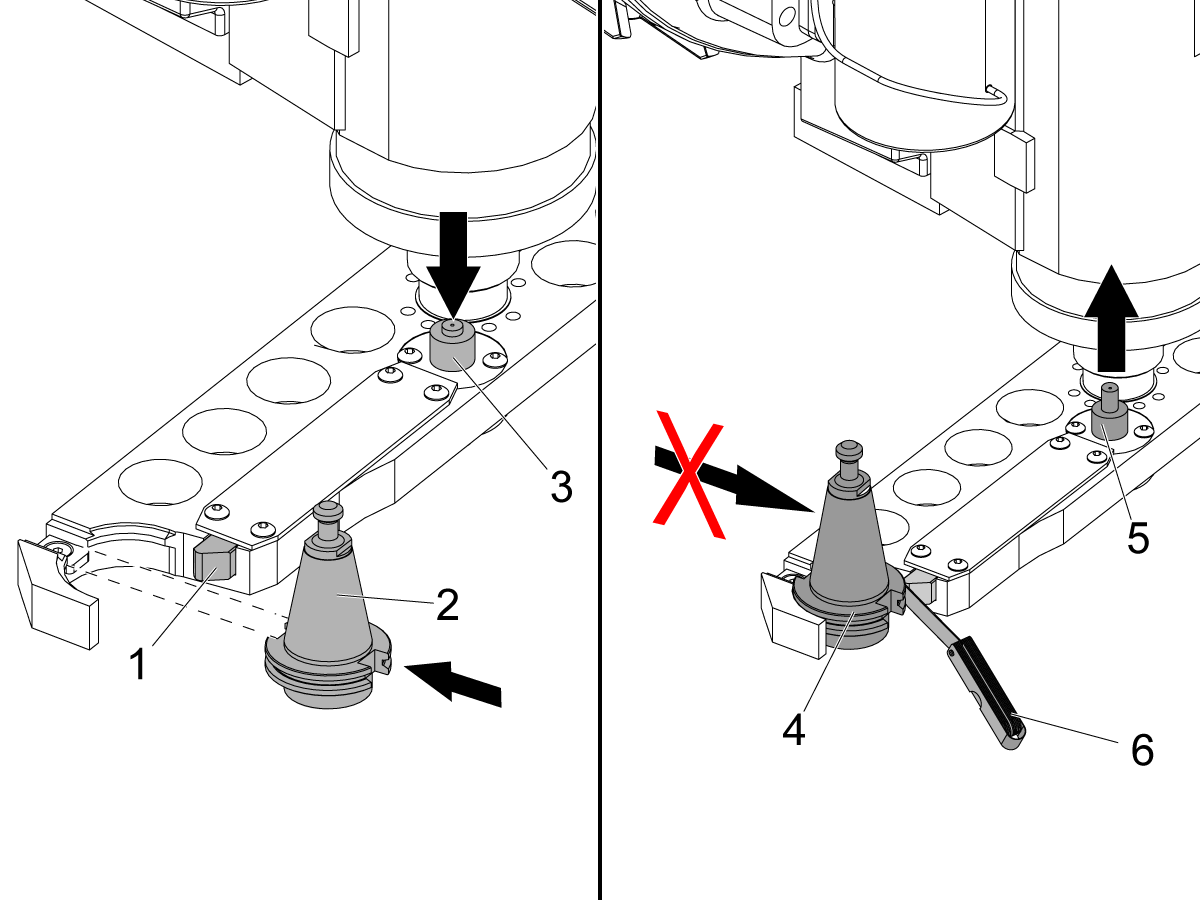
Push down on the plunger [3] and hold it down.

Put a tool holder [2] into the arm. During correct operation, the slide [1] moves in.

Release the plunger [5].

Try to remove the tool holder [4]. During correct operation, the slide does not move in and the tool holder locks in position.

Measure the space between the slide and the tool holder. Use a feeler gauge [6]. The correct space is between 0.014 in (0.36 mm) and 0.020 in (0.51 mm). If the machine is a DM-1 or DT-1, the correct space is between 0.005 in (0.13 mm) and 0.015 in (0.38 mm).

Add or remove 0.01 in (0.25 mm) shim washers, part number 45-0075,  until the space is correct.

Once the gap is set reassemble the slider assembly with the spring and washer installed. Apply a layer of Lithium Tacky Grease to the finger, spring and washer. 

9.3 Side Mount Tool Changer - Carousel and Pocket - Troubleshooting Guide

Recently Updated

Side Mount Tool Changer (SMTC) - Carousel and Pocket - Troubleshooting Guide


TG0127

Revision A - 08/2025

Introduction

EXPLODED VIEW:

  1. FBHCS 1/4-20 X 1/2
  2. CAROUSEL COVER
  3. BEARING LOCKNUT
  4. JAM NUT 5/8-18
  5. CAROUSEL
  6. CAM FOLLOWER
  7. BEARING
  8. POCKET ASSEMBLY
  9. CAROUSEL WASHER
  10. TOOL CHANGER FRAME
  11. CAROUSEL SHAFT
  12. SPACER
  13. CAM BOX
  14. SHCS 1/2-13 X 2
  15. CAROUSEL CAM ASSEMBLY
  16. POCKET STOP
  17. SHCS 1/2-13 X 5
  18. CAROUSEL MOTOR
  19. POCKET TIPPER ASSEMBLY
  20. DOUBLE ARM

Carousel

  1. Tool In Position Proximity Sensor: It lets the control know that the tool pocket is in position.
  2. Carousel Cam: A DC or Servo Motor turns this Cam that rotates the tool carousel.
  3. Tool One Proximity Sensor: It lets the control know that the tool pocket is tool one position.

Pocket

  1. Cam Follower: Keeps the pocket in the up position as the carousel rotates. The cam follower follows a groove on the carousel housing.
  2. Shaft: The axle upon which the pocket pivots up and down.
  3. Spring: Puts tension on the four plungers inside the tool pocket.
  4. Tool Pocket: Holds the tool.
  5. Plungers: The four plungers grip the tool pull stud. They are lubricated with grease.

Symptom Table

Symptom Possible Cause Corrective Action
Alarm 622 TOOL CHANGER ARM FAULT  100 PKT SMTC Carousel stopping in between pockets unable to recover. Drive sprocket moved out of the motor shaft due to failed bushing causing the idle sprocket to fail.  Replace the idle sprocket and bushing, see 100 PKT SMTC sprocket replacement section.
Alarm 625 CAROUSEL POSITIONING ERROR 100 PKT SMTC Carousel stopping in between pockets unable to recover. Drive sprocket moved out of the motor shaft due to failed bushing causing the idle sprocket to fail.  Replace the idle sprocket and bushing, see 100 PKT SMTC sprocket replacement section.
The carousel tool in position, tool one in position, pocket up or down proximity sensor is damaged or contaminated. Rotate the carousel in recovery mode and test the sensors and cabling.
No power to the carousel motor or the carousel motor is damaged. Check that the carousel can be rotated in the manual recovery mode.

VMC, HMC - Side-Mount Tool Changer - Manual Recovery

Tool change was interrupted before completion. Do a Tool Change Recovery.

VMC, HMC - Side-Mount Tool Changer - Manual Recovery

A tool change was attempted before adequate air pressure was present.
A tool change was attempted with the pocket already down.
Carousel rotation was prevented by an obstruction. Clear the carousel path.
Alarm 626 TOOL-POCKET SLIDE ERROR A tool change was attempted with the pocket already down. Do a Tool Change Recovery.

VMC, HMC - Side-Mount Tool Changer - Manual Recovery

The incoming air flow or pressure is incorrect. Correct the incoming air supply.
There is contamination in the slide guides. Clean and lubricate the slide guides.
The air cylinder for the tool pocket does not move freely. Check the air cylinder for the tool pocket.
The pocket up or pocket down proximity sensors are contaminated, damaged or have loose connections. Clean and inspect the proximity sensors.
There is a problem with the pocket up/down system. Troubleshoot the check valve, air cylinder, and solenoid.
Movement is blocked by debris. Clear debris.
The tool pocket, air cylinder, pocket slide, or slide follower is loose or damaged. Diagnose and correct.
Alarm 2066 TOOL CHANGER HOME POSITION FAULT
The pocket up and down proximity switches are in the incorrect state. Clean and inspect the proximity sensors.
The tool pocket is noisy. There is a problem with the tool-pocket stop shock-absorber. Check the tool-pocket stop shock-absorber.
The tool pocket, air cylinder, pocket slide, or slide follower is loose or damaged. Diagnose and correct.
The tool falls from the tool pocket. The toolholders or pull studs are incorrect. Check for correct tool specifications.
The spring or the plungers are worn. Check the spring and the plungers for wear.
The tool pocket moves up and down too fast for heavy tools. Install the Pocket Slow Down Service Kit (P/N 93-0254).
The tool pocket is broken. Carousel rotation was prevented by an obstruction. Clear the carousel path.
The pocket up or pocket down proximity sensors are contaminated, damaged or have loose connections. Clean and inspect the proximity sensors.
The tool pocket, air cylinder, pocket slide, or slide follower is loose or damaged. Diagnose and correct.
The carousel makes unusual noises during operation. The cam followers on the carousel need grease. Check and grease the cam followers.
The cam followers on the carousel are worn.
The tool pocket slider set screw is incorrectly adjusted. Make sure the tool pocket slider set screw is correctly adjusted. See VMC - Side-Mount Tool Changer - Pocket Slider Set Screw Adjustment procedure.
The carousel cam bearhug nuts are loose. A loose cam bearhug nut will cause rotational backlash on the carousel assembly, noise and carousel position alarms. Tighten the carousel cam bearhug nuts with a spanner wrench.
The SMTC Arm Motion Speed Is Too Fast. The tool is not flagged as heavy (H) in the tool pocket table. Tools flagged as heavy [1] in the tool pocket table, will cause the SMTC arm to rotate at 25% the speed (VFSS only).
EC/VC tool change cycle is very slow Parameter 223 Tool Changer Air Door Delay Change has a value, this should only have a value if a pnuematic door is present

Update configuration files to the latest, Parameter 223 will be set to zero. This configuration files have been backdated so that all machines will receive this updated value. 

NOTE: Remember to take a back up before loading the latest configuration files.
HSG-N 02-14-2023

Carousel Proximity Sensors

Corrective Action:

Test the tool in position sensor:

  1. Clear the alarms and go into tool changer manual recovery. Refer to VMC, HMC - Side-Mount Tool Changer - Manual Recovery.
  2. Press the left or right arrow to move the carousel. Monitor the TOOL IN POS bit on a Classic Haas Control (CHC), or SMTC_CAROUSEL_POCKET_MARK on a Next Generation Control (NGC). This bit will be 0 unless the pocket is in position. It will be 1 when the pocket is in position.
  3. If the carousel moves but the bit does not change state, remove the carousel cover. If the carousel does not move, see Section 2.
  4. To make sure the proximity sensor is not tripped, turn the carousel until the flat side of the cam [2] faces the proximity sensor [1].
  5. Touch the end of the proximity sensor with a screwdriver. Watch for the light to change, and monitor the TOOL IN POS or SMTC_CAROUSEL_POCKET_MARK value.
  6. If the light or the bit value does not change state, use the Proximity Sensor - Troubleshooting Guide to troubleshoot the proximity sensors.

Test the tool one position sensor:

  1. Find the proximity sensor [3].
  2. Press the left or right arrow to move the carousel. Monitor the TOOL ONE POS bit on a Classic Haas Control (CHC), or SMTC_CAROUSEL_POCKET_ONE on a Next Generation Control (NGC). This bit should change state once per carousel revolution at pocket one.
  3. Touch the end of the proximity sensor with a screwdriver. Watch for the light to change, and monitor the TOOL ONE POS (CHC) or SMTC_CAROUSEL_POCKET_ONE (NGC) bit value.
  4. If the sensor does not change state, use the Proximity Sensor - Troubleshooting Guide to troubleshoot the proximity sensors.

Carousel Motor

Corrective Action:

  1. With the motor connected, check for voltage at the back of the motor power connector.
  2. Set your meter to DC voltage.
  3. Set the DC voltage range on your meter to at least 200 VDC.
  4. Select the Min/Max mode to capture the voltage.
  5. Reset all the alarms, and go into tool changer manual recovery VMC, HMC - Side-Mount Tool Changer - Manual Recovery.
  6. Press the left or right arrow to move the carousel.
  7. The meter should record voltage between +/- 150 and +/-170 VDC in brief pulses.
  8. If you get the correct voltage and motor does not turn, the motor is damaged. If the voltage is incorrect, refer to:
    • Next Generation Control - I/O PCB - Troubleshooting Guide
    • Classic Haas Control - I/O PCB - Troubleshooting Guide

100 Pocket SMTC Sprocket Replacement

Corrective Action:

To replace the idler Sprockets [1] and the bushing [2], you must first wrap a chain or strap around the carousel and frame, this is to eliminate the carousel from freely spinning. 

WARNING: If the carousel is not tied it can cause serious injury. 

Incoming Air Flow or Pressure

Corrective Action:

  • Make sure that the air hose to the machine is the correct diameter.
  • Make sure that the air compressor supplies the correct air pressure and air flow.
  • Command a tool change on the machine. When the machine has the correct air pressure and flow, the needle on the air pressure gauge should not drop more than 10 PSI (0.70 bar) during a tool change. This test confirms that the air pressure and air flow into the machine is correct.

Refer to the "Compressed Air" requirements for your machine on New Machine Pre-Installation.

Pocket Slide Guides

Corrective Action:

  1. Visually examine the slide guides [1] for the tool pocket. Remove all contamination.
  2. Lubricate the surfaces with red grease.
  3. Go into tool changer manual recovery VMC, HMC - Side-Mount Tool Changer - Manual Recovery.
  4. Press up or down arrow to move the tool pocket. Make sure the pocked moves smoothy into and out of the tool change position.

Pocket Air Cylinder

Corrective Action:

  1. Power off the machine and disconnect the air supply.
  2. Find the tool pocket cylinder.
  3. If equipped, remove the pilot-operated check valve [1] and the hose to the bottom of the cylinder. For machines that do not have a pilot-operated check valve, disconnect the top and bottom hoses on the air cylinder.
  4. Move the cylinder [2] up and down.
  5. Make sure that the piston moves freely. Spray a small quantity of silicon lubricant into the cylinder to lubricate the piston seal.
  6. If the piston does not move freely, the tool pocket air cylinder is damaged.
  7. Make sure the air supply to the machine is clean and dry.

Pocket Up / Down Proximity Sensors

Corrective Action:

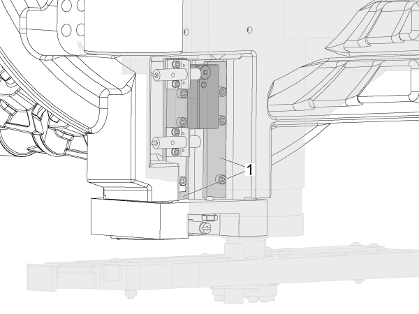
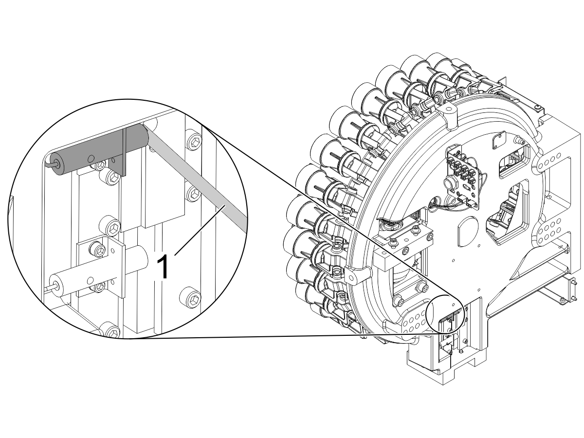
Make sure the pocket up and pocket down proximity sensors [1] are clean. Contamination on the switches may cause the carousel to rotate and break a pocket before it is in the fully up position.

The DIAGNOSTICS page shows the state of the sensors. If the POCKET DOWN or POCKET UP (CHC), or the SMTC_TOOL_POCKET_UP or SMTC_TOOL_POCKET_DOWN (NGC), bits do not change state, the sensors may have chips or contamination on them.

Make sure that the tool pocket is up. Press [PARAMETER/DIAGNOSTIC] and go to the I/O tab.

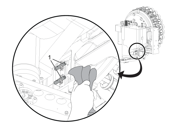
Touch the end of the proximity sensor with a screwdriver [1]. This test can cause Alarm 626. Ignore the alarm. The proximity sensor operates correctly if the Pocket Down (CHC), SMTC_Pocket_Down (NGC), value changes from a 1 to a 0. Continue troubleshooting if the diagnostic value does not change.

To troubleshoot the pocket up sensor, make sure that the tool pocket is down. Touch the end of the proximity sensor with a screwdriver and monitor Pocket Up (CHC), SMTC_Pocket_Up (NGC). The value must change from a 1 to a 0.

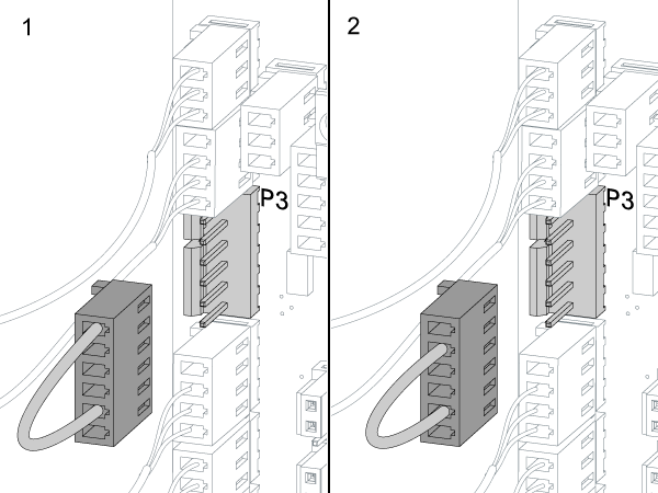
Do these steps on CHC machines only: Find where the 820 cable connects to the I/O PCB at P3. Use an electrical jumper (P/N 33-8521) at P3 [1]. If the Pocket Down value changes from a 1 to a 0, the I/O PCB operates correctly. Replace the SMTC cable assembly. Refer to Proximity Sensor How it Works and Troubleshooting - Video. Use the Proximity Sensor - Troubleshooting Guide to troubleshoot the proximity sensors.

To troubleshoot the pocket up sensor, reconfigure the jumper at P3 as shown [2]. Monitor the Pocket Up value. If the value changes from a 1 to a 0, the I/O PCB operates correctly. Replace the SMTC cable assembly.

If the Pocket Down or Pocket Up value does not change to a 0 when tested, refer to:

  • Next Generation Control - I/O PCB - Troubleshooting Guide
  •  I/O PCB - Troubleshooting Guide (Classic Haas Control)


Pocket Solenoid

Corrective Action:

Be sure to troubleshoot the solenoid correctly. Refer to Solenoid - Troubleshooting Guide to troubleshoot the system. Refer to "4 Port Solenoid Applications."

Tool Contamination

Corrective Action:

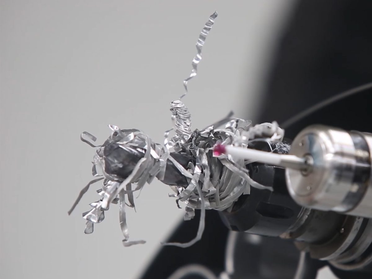
Make sure the tool is not contaminated by debris. Look for and remove any "nests" of chips in the mechanism.

Refer to TOTD Episode 33 - Stringy Chips Wrapped Around Your Tools? Chip Clear Solution to troubleshoot the system.

Pocket Shock Absorber

Symptom: The tool pocket is noisy.

Possible Cause: There is a problem with the tool-pocket stop shock-absorber.

Corrective Action:

  1. Make sure that the tool pocket is in the up position [1].
  2. Push the shock-absorber in with your thumb [3].
  3. Release the shock-absorber [2].

For CALM machines, replace the shock-absorber with the correct orifice (P/N: 58-0093) [4] between the solenoid and the muffler if:

  • There is no resistance when you push the shock-absorber.
  • The shock-absorber does not extend after you push it.

 Note: For all other machines, replace the shock-absorber with a new shock-absorber.

Tool Holders and Pull Studs

Symptom: The tool falls from the tool pocket. The tool cannot be removed from the pocket.

Possible Cause: The toolholder or pull studs are incorrect.

Corrective Action:

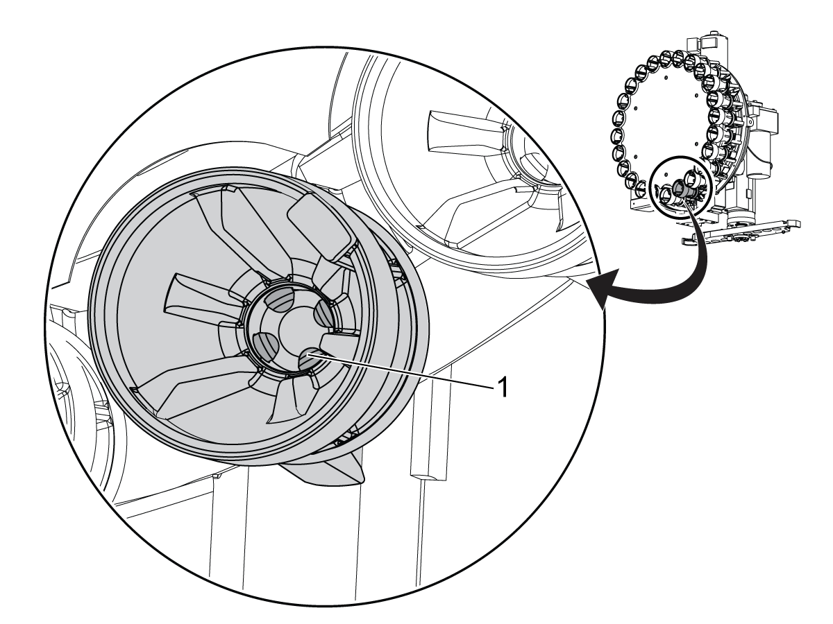
If the tool cannot be removed, remove the garter spring [3]. Wiggle the tool to loosen the plungers [1]. Be careful not to lose any plungers. Remove the tool. Replace spring.

Refer to the Toolholder and Pull Stud Information document for the correct toolholder and pull stud [2] information.

Pocket Spring and Plungers

Corrective Action:

        BT/CT pocket

  1. Make sure that the (4) plungers [1] are intact in each of the pockets.
  2. Inspect the plungers for wear. Replace them if they are worn.
  3. Make sure that the hook on the spring is not on top of any of the plungers.
  4. Clean all of the debris from the tool pockets and lubricate the plungers [1] with grease. Apply grease to the tool pull stud.

Refer to Replace a Tool Pocket on Your Haas Side Mount Tool Changer (SMTC) - Video for more information on how to remove the pocket.

Some pockets use leaf springs. Look for broken leaf springs. They are stacked (2) per corner. Replace any broken leaf springs.

        HSK pocket

  1. Make sure that the collet assembly is intact in each of the pockets.
  2. Inspect the (3) plungers and center cap in the collet assembly for wear. Replace them if they are worn. 
  3. Inspect the rest of pocket for any damage. Replace if it is needed.
  4. Clean all of the debris from pocket and lubricate the collet assembly with grease to ensure smooth operation.

Refer to HSK Pocket and Plunger - Replacement  for more information on replacing the HSK pocket.


Pocket Slow Down Kit

Corrective Action:

Install the Pocket Slow Down Service Kit (P/N 93-0254). This kit restricts the air escaping from the pocket up/down cylinder to slow down the pocket.

Refer to the Toolholder and Pull Stud Information document.

9.4 Track Tool Changer - TSG

Recently Updated

Track Tool Changer - Troubleshooting Guide


TG0147

UNDER CONSTRUCTION Revision A - 08/2025

Recently Viewed Items

You Have No Recently Viewed Items Yet

Feedback
Haas Logo

Haas Delivered Price

This price includes shipping cost, export and import duties, insurance, and any other expenses incurred during shipping to a location in France agreed with you as a buyer. No other mandatory costs can be added to the delivery of a Haas CNC Product.

KEEP UP WITH THE LATEST HAAS TIPS AND TECHNOLOGY...

Sign up now!   

HAAS TOOLING ACCEPTS THE FOLLOWING:

  • Service & Support
  • Owners
  • Request Service
  • Operator Manuals
  • Haas Parts
  • Rotary Repair Request
  • Pre-Install Guides
  • Shopping Tools
  • Build & Price a New Haas
  • Available Inventory
  • The Haas Price List
  • CNCA Financing
  • About Haas
  • Accessibility Statement
  • DNSH Statement
  • Export Compliance
  • Careers
  • Certifications & Safety
  • Contact Us
  • History
  • Terms & Conditions
  • Haas Tooling Terms & Conditions
  • Privacy
  • Warranty
  • Haas Community
  • Haas Certification Program
  • Haas Motorsports
  • Gene Haas Foundation
  • Haas Technical Education Community
  • Events
  • Join the Conversation
  • Facebook
  • X
  • Flickr
  • YouTube
  • LinkedIn
  • Instagram
  • TikTok
© 2026 Haas Automation, Inc – CNC Machine Tools

This site is protected by reCAPTCHA and the Google Privacy Policy and Terms of Service apply.

2800 Sturgis Rd., Oxnard, CA 93030
Toll Free: (888) 817-4446 / Fax: 805-278-8554