My Haas 환영합니다,
!
Haas Tooling MyHaas/HaasConnect 로그인 등록 Haas Tooling MyHaas/HaasConnect 로그아웃 환영합니다, 내 기계 최근 활동 내 견적 내 계정 내 사용자 로그아웃
담당 대리점 찾기
  1. 언어 선택
    1. English
    2. Deutsch
    3. Español - ES
    4. Español - MX
    5. Français
    6. Italiano
    7. Português
    8. Český
    9. Dansk
    10. Nederlands
    11. Magyar
    12. Polski
    13. Svenska
    14. Türkçe
    15. 中文
    16. Suomi
    17. Norsk
    18. الإنجليزية
    19. български
    20. Hrvatski
    21. Ελληνικά
    22. Română
    23. Slovenský
    24. Slovenščina
    25. 한국어
    26. 日本語
    27. Українська
  • 기계 Main Menu
    • 수직 밀
      수직 밀
      수직 밀 View All
      • 수직 밀
      • VF 시리즈
      • 유니버설 기계
      • VR 시리즈
      • VP-5 프리즈매틱
      • 팔레트 교환 VMC
      • 미니밀
      • 몰드 기계
      • 고속 드릴 센터
      • 드릴/탭/밀 시리즈
      • 툴룸 밀
      • Pocket Mill
      • 컴팩트 밀
      • 갠트리 시리즈
      • SR 시트 라우터
      • 초대형 VMC
      • 이중 컬럼 밀
    • 멀티 축 솔루션
      멀티 축 솔루션
      멀티 축 솔루션 View All
      • 멀티 축 솔루션
      • Y축 선반
      • 5축 밀
    • 선반
      선반
      선반 View All
      • 선반
      • ST 시리즈
      • 이중 스핀들
      • 박스 웨이 시리즈
      • 툴룸 선반
      • 척커 선반
      • 포켓 선반
      • Haas 봉재 이송장치
    • 수평 밀
      수평 밀
      수평 밀 View All
      • 수평 밀
      • 50-테이퍼
      • 40-테이퍼
    • 로터리 및 인덱서
      로터리 및 인덱서
      로터리 및 인덱서 View All
      • 로터리 및 인덱서
      • 로터리 테이블
      • 인덱서
      • 5축 로터리
      • 초대형 로터리
    • 자동화 시스템
      자동화 시스템
      자동화 시스템 View All
      • 자동화 시스템
      • 밀 자동화
      • 선반 자동화
      • 자동 공작물 적재장치
      • 자동화 모델
    • 데스크톱 기계
      데스크톱 기계
      데스크톱 기계 View All
      • 데스크톱 기계
      • 데스크톱 밀
      • 데스크톱 선반
      • 제어 시뮬레이터, 표준
      • 제어 시뮬레이터, 고급
    • 공장 장비
      공장 장비
      공장 장비 View All
      • 공장 장비
      • 니형 밀
      • Haas 수동 선반
      • Haas 톱
    • 제작 기계
      제작 기계
      제작 기계 View All
      • 제작 기계
      • 레이저 절삭 기계
      • CNC 프레스 브레이크
    • 빠른 링크 특별 시리즈  특별 시리즈 
      EU 시리즈 EU 시리즈 제작 및 가격 | 가격 목록 제작 및 가격 | 가격 목록 재고품 기계 재고품 기계 신제품 신제품 첫 CNC 첫 CNC
      공구 쇼핑
      • Haas 제품 제작 및 가격
      • 가격 목록
      • 사용 가능한 재고
      • CNCA 파이낸싱
      상담을 받고 싶으신가요?

      Haas Factory Outlet (HFO)은 고객님의 질문에 답변을 드리며 가장 좋은 선택지를 안내해 드립니다.

      CONTACT YOUR DISTRIBUTOR >
  • 옵션 Main Menu
    • The Haas Control 밸류 옵션 패키지
      밸류 옵션 패키지
      밸류 옵션 패키지 View All
      • 밸류 옵션 패키지
    • Product Image 스핀들
      스핀들
      스핀들 View All
      • 스핀들
    • Product Image 공구 교환장치
      공구 교환장치
      공구 교환장치 View All
      • 공구 교환장치
    • Product Image 4 | 5축
      4 | 5축
      4 | 5축 View All
      • 4 | 5축
    • Product Image 터렛 및 라이브 툴링
      터렛 및 라이브 툴링
      터렛 및 라이브 툴링 View All
      • 터렛 및 라이브 툴링
    • Product Image 검사
      검사
      검사 View All
      • 검사
    • Haas 칩 및 절삭유 관리 칩 및 절삭유 관리
      칩 및 절삭유 관리
      칩 및 절삭유 관리 View All
      • 칩 및 절삭유 관리
    • Haas Control Haas Control
      Haas Control
      Haas Control View All
      • Haas Control
    • Product Image 제품 선택 사항
      제품 선택 사항
      제품 선택 사항 View All
      • 제품 선택 사항
    • Product Image 툴링 및 픽스처링
      툴링 및 픽스처링
      툴링 및 픽스처링 View All
      • 툴링 및 픽스처링
    • Product Image 워크홀딩
      워크홀딩
      워크홀딩 View All
      • 워크홀딩
    • Product Image 5축 솔루션
      5축 솔루션
      5축 솔루션 View All
      • 5축 솔루션
      • 5 Easy Steps to 5-Axis
    • Product Image 자동화
      자동화
      자동화 View All
      • 자동화
    • 빠른 링크 특별 시리즈  특별 시리즈 
      EU 시리즈 EU 시리즈 제작 및 가격 | 가격 목록 제작 및 가격 | 가격 목록 재고품 기계 재고품 기계 신제품 신제품 첫 CNC 첫 CNC
      공구 쇼핑
      • Haas 제품 제작 및 가격
      • 가격 목록
      • 사용 가능한 재고
      • CNCA 파이낸싱
      상담을 받고 싶으신가요?

      Haas Factory Outlet (HFO)은 고객님의 질문에 답변을 드리며 가장 좋은 선택지를 안내해 드립니다.

      CONTACT YOUR DISTRIBUTOR >
  • Why Haas Main Menu
      Haas의 차이를 알아보세요
    • Haas여야만 하는 이유
    • MyHaas
    • 교육 커뮤니티
    • Industry 4.0
    • Haas 인증
    • 고객 사용후기
  • 서비스 Main Menu
      Haas Service 에 오신 것을 환영합니다
      서비스 홈 조작자 설명서 방법 절차 문제해결 가이드 예방적 유지관리 Haas 부품 Haas Tooling 동영상
  • 동영상 Main Menu
My Haas 환영합니다,
!
Haas Tooling MyHaas/HaasConnect 로그인 등록 Haas Tooling MyHaas/HaasConnect 로그아웃 환영합니다, 내 기계 최근 활동 내 견적 내 계정 내 사용자 로그아웃
담당 대리점 찾기
  1. 언어 선택
    1. English
    2. Deutsch
    3. Español - ES
    4. Español - MX
    5. Français
    6. Italiano
    7. Português
    8. Český
    9. Dansk
    10. Nederlands
    11. Magyar
    12. Polski
    13. Svenska
    14. Türkçe
    15. 中文
    16. Suomi
    17. Norsk
    18. الإنجليزية
    19. български
    20. Hrvatski
    21. Ελληνικά
    22. Română
    23. Slovenský
    24. Slovenščina
    25. 한국어
    26. 日本語
    27. Українська
×

검색 결과

Web Pages

Images

    • <
    • 1
    • >

5 - HC10 - Installation

Haas Cobot Package - Operator's/Service Manual


  • 0 - Haas 코봇 - 목차
  • 1 - Haas Cobot - Introduction
  • 2 - Haas Cobot - Legal Information
  • 3 - Haas Cobot - Safety
  • 4 - HC5 - Installation
  • 5 - HC10 - Installation
  • 6 - HC15 - Installation
  • 7 - HC30 - Installation
  • 8 - Haas Cobot - Fence/Interlock Installation
  • 9 - Haas Cobot - Area Scanner Installation
  • 10 - Haas Cobot - Light Curtain Installation
  • 11 - Haas Cobot - Operation
  • 12 - Haas Cobot - Maintenance
  • 13 - Haas Cobot - Troubleshooting

Go To :

  • 5.1 VMC 설치
  • 5.2 선반 설치
  • 5.3 DM/DT/MM/DC-1/UMC-350 설치
  • 5.4 UMC-400/500 설치

5.1 VMC 설치

Recently Updated

Haas Cobot 10 (HC10) - VMC - 설치


AD0714

개정판 C - 2025년 9월

Introduction

이 절차는 Haas 10KG 코봇(HC10)을 설치하는 방법을 보여줍니다.

 참고: CNC 기계와 로봇으로 구성된 Haas 설계 작업 셀은 CE 요건을 준수하는 것으로 평가되었습니다. Haas 셀 디자인에 대해 변경 또는 변형하는 경우 해당 표준을 준수하는지 평가해야 하며 이는 사용자/통합 회사의 책임입니다.

Updated

기계 요구 사항:

  • 100.24.000.1001 버전 이상
  • HR5.51H.16.beta.20231213.zip 버전 또는 HR6.4.9.tmp20240919.zip 버전
  • VF-1/2 및 VM-2 제작일:  (각 절차의 기계 요구 사항 참조) 
  • DC-2
  • Haas 자동문 
  • Haas 자동 창
  • 34-349xB I/O 보드 이상
  • 93-1000610 REMOTE JOG HANDLE TOUCH LCD (RJH-XL) REMOTE JOG HANDLE - XL
  • 공구 요구 사항

    • 미니 일자 드라이버

    고정 요구 사항

    •  Haas 10KG 코봇(HC10)은 Haas에서 정의한 공작물 크기 및 중량 제한에 따라 사용할 때 충분히 안정적인 받침대/테이블과 함께 Haas에서 구성 및 판매합니다. 
    중요:  Hans 코봇에 대한 자세한 내용은 Elfin 소프트웨어용 Hans 로봇 작동 설명서를 참조하십시오.

    코봇 옵션을 Haas 기계에 설치할 수 있는 세 가지 시나리오가 있습니다.

    1. 코봇 옵션이 기계와 동시에 주문되었습니다. 코봇과 기계가 모두 함께 설치되고 있습니다.
    2. 코봇 옵션은 이전에 설치된 기계에 설치할 수 있도록 주문됩니다.
    3. 코봇 옵션은 이전에 기계에 설치되었지만 이제 다른 Haas 기계로 이동합니다.

    시나리오 2 및 3에서는 Haas 기계의 일련 번호로 추가 부품을 주문해야 합니다. 다른 시나리오에서 필요한 부품은 아래 표를 참조하십시오.

    시나리오 1 - 코봇과 기계를 함께 주문하고 설치합니다.

    구성품 부품 번호 설명
    코봇과 기계를 함께 주문할 때 추가 부품을 주문할 필요가 없습니다

    시나리오 2 - 기존 Haas 기계에 현장 설치된 코봇

    구성품 부품 번호 설명
    주문하기 전에 HAAS 기계에 이러한 특징 및 파라미터가 이미 있는지 확인하십시오
    로봇 기능 잠금 해제 파라미터 93-1001031 키트는 Haas 기계에서 로봇 기능을 활성화합니다. 이 키트가 필요한지 확인하려면 Haas 제어의 기능 탭으로 이동하여 로봇 옵션이 강조 표시되어 있는지 확인하십시오. 이 키트에는 물리적 부품이 포함되어 있지 않습니다
    부하 유형 안전 파라미터 93-1000997 프론트 자동화 안전 파라미터 - 키트는 코봇이 Haas 기계의 전면 도어를 통해 공작물을 적재할 때 필요합니다. 이 키트에는 물리적 부품이 포함되어 있지 않으므로 자동 도어 옵션을 별도로 구입하여 설치해야 합니다.
    또는  
    93-1000996 사이드 자동화 안전 파라미터 - 키트는 코봇이 Haas 기계의 측면 창을 통해 공작물을 적재할 때 필요합니다. 이 키트에는 물리적 부품이 포함되어 있지 않으며 자동창 옵션은 별도로 구입하여 설치해야 합니다.

    시나리오 3 - 코봇이 한 기계에서 다른 Haas 기계로 이전되고 있습니다

    참조
    구성품 부품 번호 설명
    코봇 통합 키트 통합 키트 호환성 차트코봇과 인터페이스하기 위해 Haas 기계에 부품을 설치하려면 키트가 필요합니다. 여기에는 인터페이스 상자, 도어 스위치 등뿐만 아니라 로봇 잠금 해제 기능 파라미터도 포함됩니다. 이 키트는 일반적으로 코봇을 주문할 때 포함되므로 코봇을 새 Haas 기계로 전송할 때만 구매해야 합니다. 
    부하 유형 안전 파라미터 93-1000997 프론트 자동화 안전 파라미터 - 키트는 코봇이 Haas 기계의 전면 도어를 통해 공작물을 적재할 때 필요합니다. 이 키트에는 물리적 부품이 포함되어 있지 않으므로 자동 도어 옵션을 별도로 구입하여 설치해야 합니다.
    또는  
    93-1000996 사이드 자동화 안전 파라미터 - 키트는 코봇이 Haas 기계의 측면 창을 통해 공작물을 적재할 때 필요합니다. 이 키트에는 물리적 부품이 포함되어 있지 않으며 자동창 옵션은 별도로 구입하여 설치해야 합니다.
    안전 장치 08-1899 다중 측면 라이트 커튼 키트 - 안전 장치가 첫 번째 기계에서 전송되지 않고 두 번째 Haas 기계에 자체 안전 장치가 필요한 경우 키트가 필요합니다. 이 키트는 4면 보호 장벽을 만듭니다.
    또는  
    08-1948 5면 라이트 커튼 키트 - 안전 장치가 첫 번째 기계 기계에서 전송되지 않고 두 번째 Haas 기계에 자체 안전 장치가 필요한 경우 키트가 필요합니다. 이 키트는 5면 보호 장벽을 만듭니다.
    또는  
    08-1987 레이저 영역 스캐너 키트 - 안전 장치를 첫 번째 기계에서 두 번째 Haas 기계로 이전하지 않을 경우, 기계와 두 번째 Haas 기계에 별도의 안전 장치가 필요할 때 이 키트가 필요합니다. 이 영역 스캐너의 감지 거리는 4미터입니다.

    Mill Setup

    1

    도어 양쪽에서 다음을 완료하십시오:

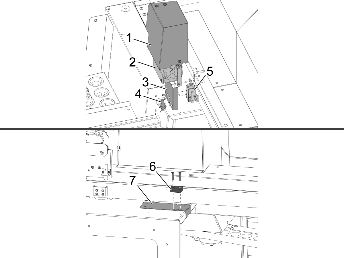
    오토 도어 모터 커버[1]와  오토 도어 모터 어셈블리[2]를 제거합니다.

    새 근접도 스위치 브래킷[3]을 기존 근접도 스위치 블록[5]에 설치합니다.

    항상 도어를 열고 근접도 스위치[4]를 브래킷[3]에 설치합니다.

     중요: VMC 키트에는 2개의 드릴 템플릿이 포함되어 있습니다. VF 템플릿 [8]과 DC-2 기계에 특정한 고유한 템플릿 [9]이 있습니다. DC-2 기계에서는 표준 VF 템플릿 대신 DC-2 템플릿을 사용해야 합니다.

    도어 열림 플래그[6]용 드릴 가이드[7]를 설치하고 도어의 판금을 통해 2x 10-32 구멍을 뚫습니다.

    • 드릴 크기: #21 또는 5/32"
    • 탭 10-32 NF

    템플릿 제거 후 2x 플랫 캡 스크루로 도어 오픈 플래그를 설치합니다. 오토도어 모터 어셈블리, 브래킷 및 덮개를 재설치합니다.

    제공된 쉼을 사용하여 근접도 스위치와 도어 오픈 플래그 사이의 높이를 설정합니다.

    2

    전면 로딩 로봇: 

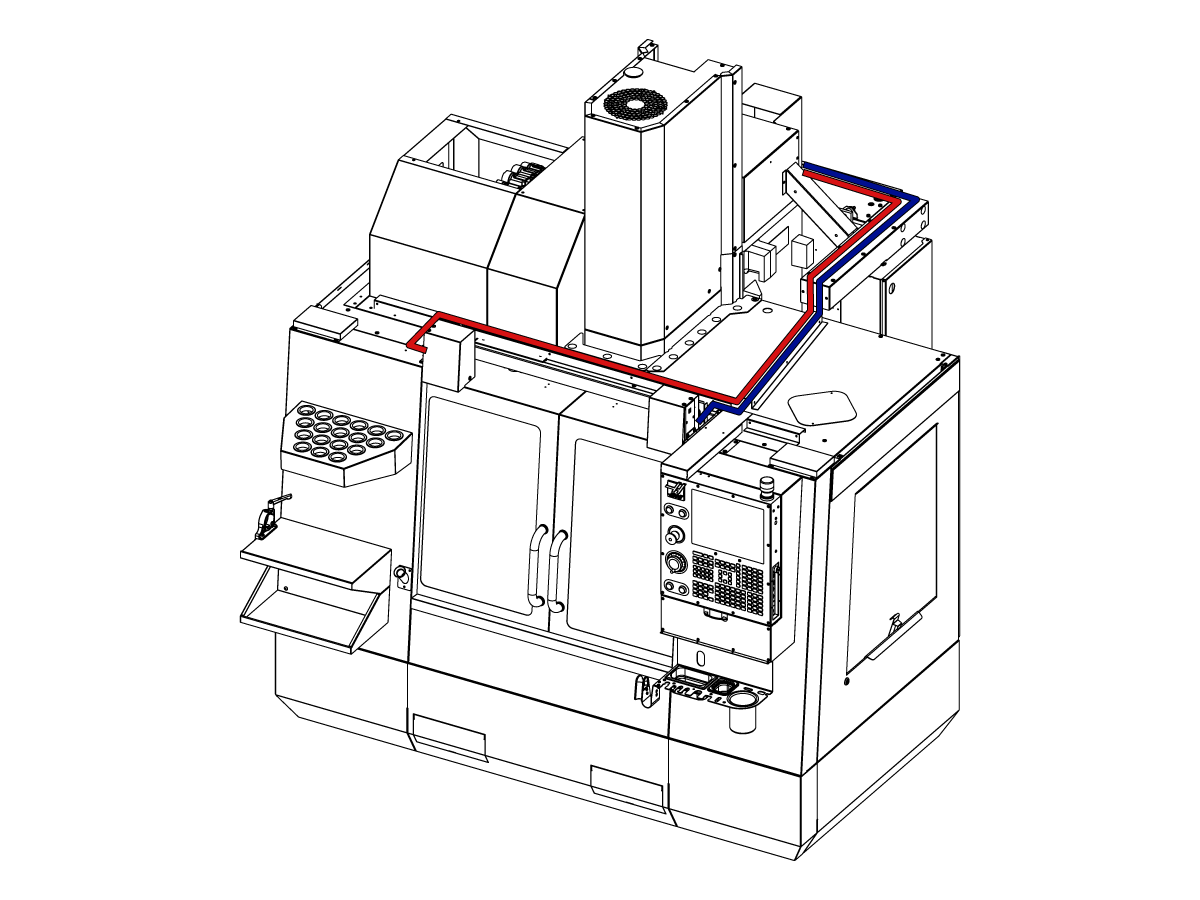
    그림과 같이 도어 완전 개방 케이블을 제어 캐비닛에 배선합니다.

    기계를 끄십시오.

    32-0807 PROX NO LEFT DOOR FULLY OPEN을 SIO PCB P27에 연결합니다.

    32-0856 PROX NO RIGHT DOOR FULLY OPEN을 SIO PCB P72에 연결합니다.

    기계를 켜십시오. 

    3

    측면 로딩 로봇:

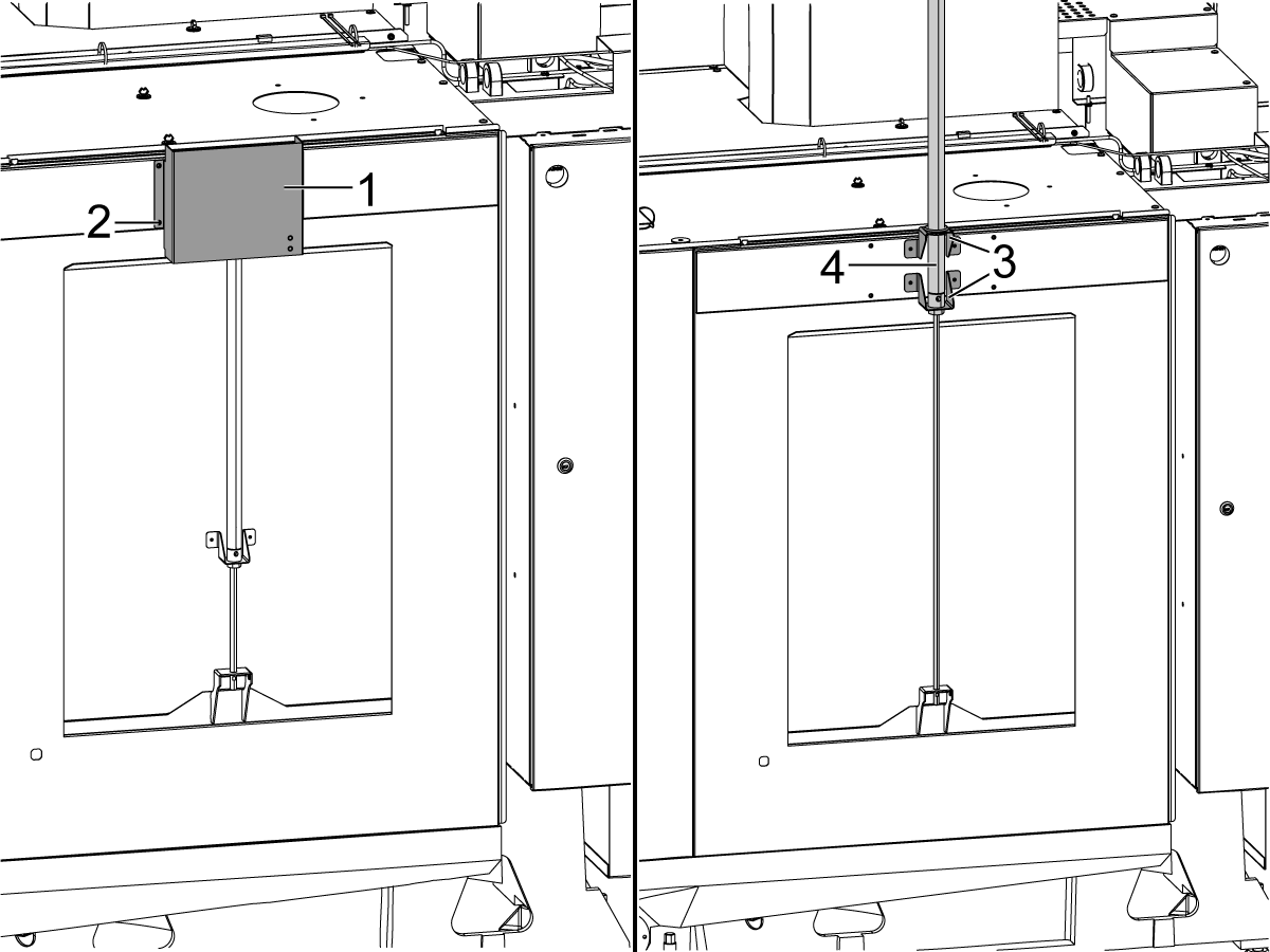
    자동창의 에어 실린더[4]를 노출시키기 위해 커버[1]와 하드웨어[2]를 제거합니다. 그림과 같이 브래킷[3]과 에어 실린더가 부착되도록 에어 실린더[4]를 들어 올립니다.

    회색 및 노란색 에어 라인 튜브는 자동 창 공기 실린더에 연결해야 하며 공기 실린더의 포트에는 각 튜브가 연결되는 위치를 표시하기 위해 회색 및 노란색 지퍼 타이가 있습니다.

    자동 창의 에어 실린더 위에 커버 [2]를 설치합니다.

    4

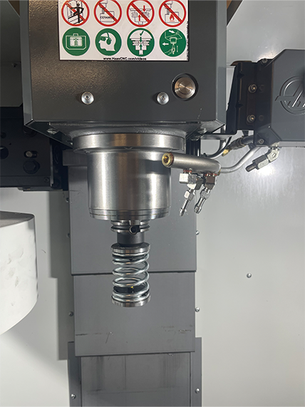
    • APL 스프링 푸셔는 25mm 또는 1인치 툴 홀더에 맞는 자루로 제작
    • 이 공구는 공구 캐로슬에서 공구 홀더를 조여야 합니다.
    • 다음 단계를 모든  프로그램의 시작 부분에 프로그래밍하여 공작물이 바이스에 올바르게 장착되도록 프로그래밍하십시오.
      • 공작물 위에 있는 스프링 푸셔 찾기
      • Z축을 움직여 스프링을 약 0.50인치 또는 12.7mm로 압축
      • 1초의 일시 정지로 바이스 열기
      • 1초의 일시 정지로 바이스 닫기

    참고: 스프링 푸셔의 부품 번호는 다음과 같습니다. 

    • 30-12642 SPRING PUSHER.  25mm 또는 1.0인치 홀더는 별도로 판매됩니다.

    Cobot Installation

    1

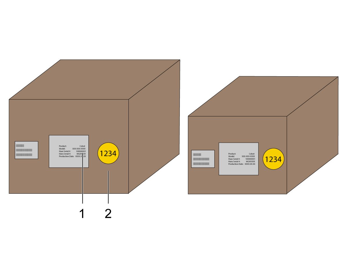
    코봇 과제어 박스가 일치하는 일련 번호와 일치하는 세트에서 왔는지 확인합니다.

    Haas 일련 번호[1]가 있는 흰색 데칼이 있습니다. 두 상자에서 모두 동일한지 확인하십시오.

    식별 번호[2]가 있는 노란색 원 데칼이 있습니다. 두 상자에서 모두 동일한지 확인하십시오.

    2

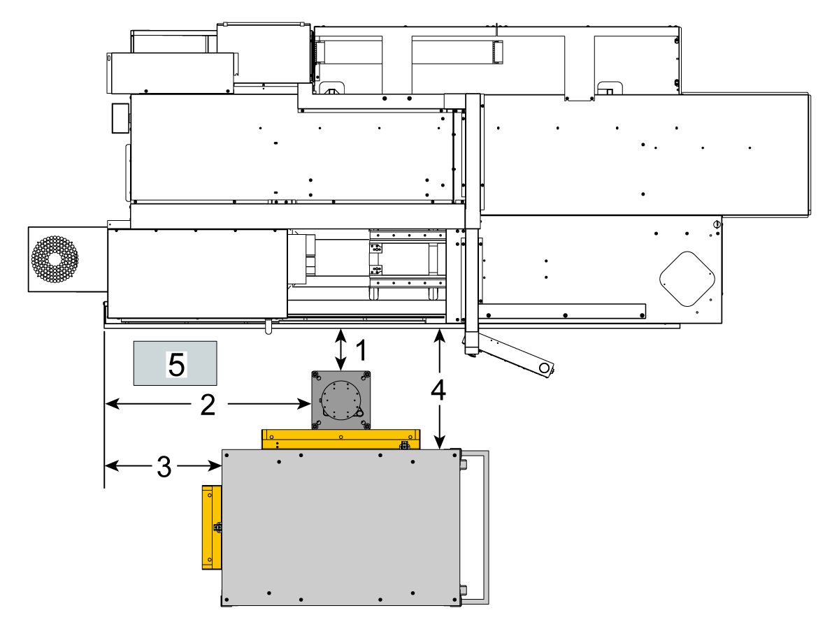
    기계 스커트에서 받침대 측면까지의 거리를 측정합니다.

     참고: 다음 치수는 권장 거리입니다. 위치는 사용자 응용 장치에 따라 다를 수 있습니다.

    다음 단계의 치수를 전면 및 측면 로딩 코봇의 기준으로 사용하십시오. 

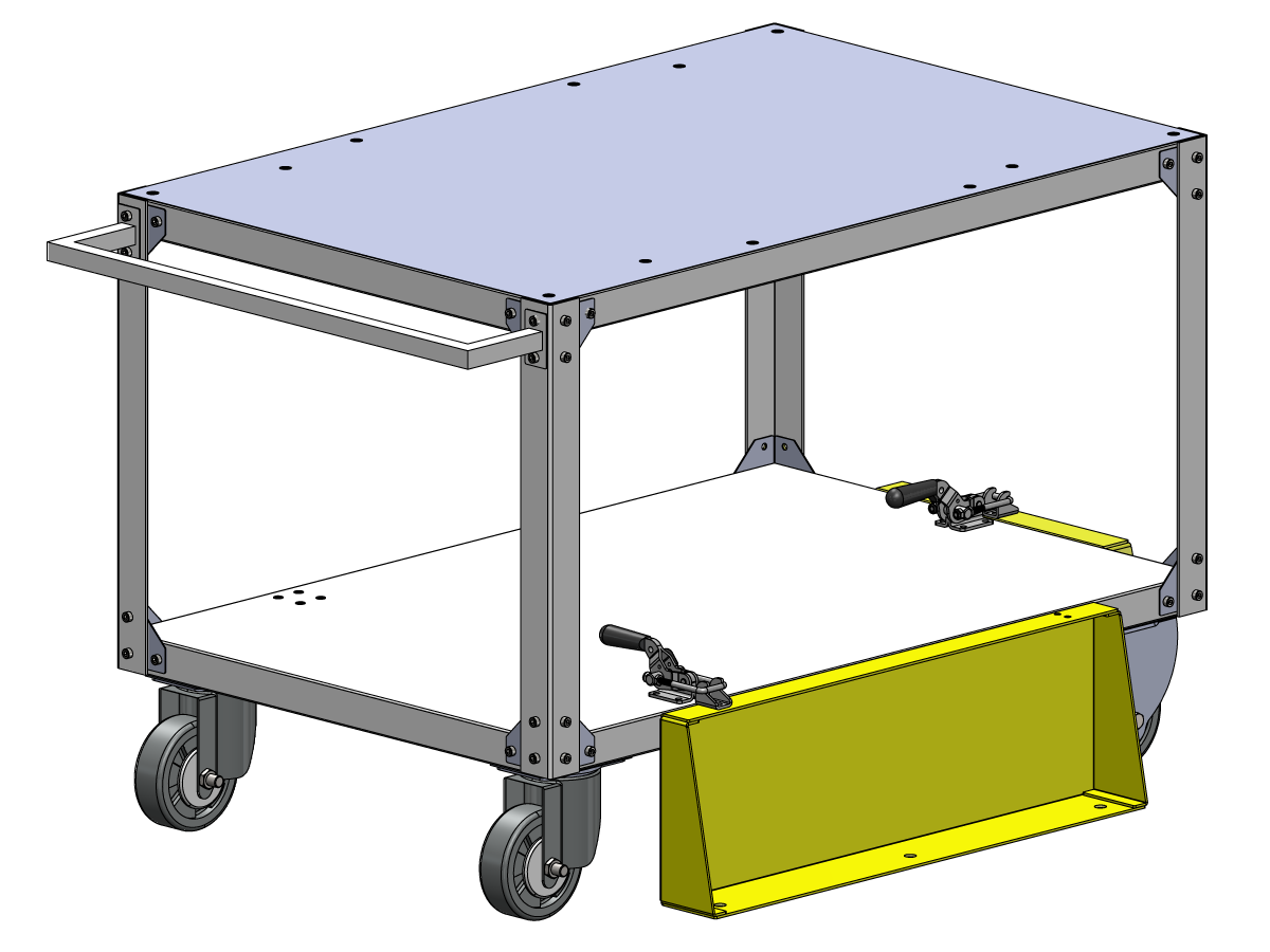
    Haas 코봇 10은 Haas 코봇 받침대와 페어링하는 것이 좋습니다. 이 받침대는 Haas에서 정의한 공작물 크기 및 중량 제한에 따라 사용할 때 충분히 안정되도록 구성되어 있습니다. 

    3

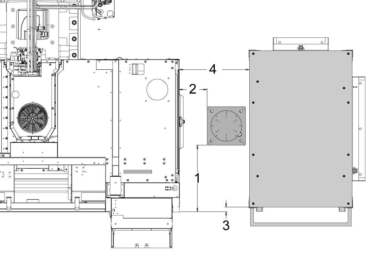
    전면 적재:

    기계를 기준으로 다음 위치에 받침대와 공작물 테이블을 배치합니다.

    치수 야드파운드법(인치) 미터법(cm)
    기계 전면에서 받침대 전면까지 [1] 5.5인치 14cm.
    기계 왼쪽에서 받침대 왼쪽 측면까지 [2] 29.5인치 75cm
    기계 전면에서 공작물 테이블 [4] 22인치 56cm
    기계 왼쪽에서 공작물 테이블[4]의 왼쪽 10인치 25.4cm

    4

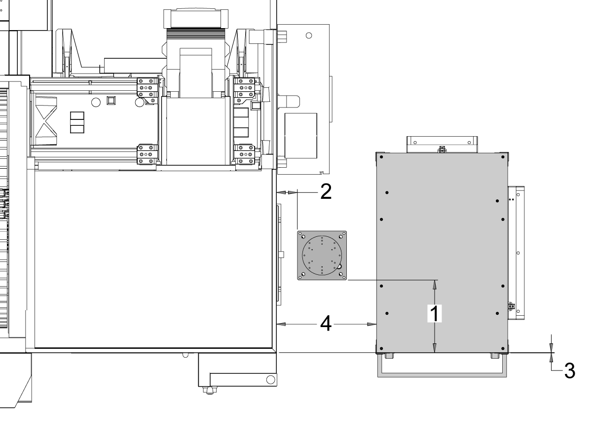
    측면 적재:

    기계를 기준으로 다음 위치에 받침대와 공작물 테이블을 배치합니다.

    치수 야드파운드법(인치) 미터법(cm)
    기계 전면에서 받침대 [1] 왼쪽 측면까지 20.5인치 52cm
    기계 오른쪽에서 받침대 [2] 전면까지 8.5인치 21.6cm
    기계 전면에서 공작물 테이블 [3]의 왼쪽 1.5인치 3.8cm
    기계 오른쪽에서 공작물 테이블 [4]의 전면 21.5인치 54.6cm

    5

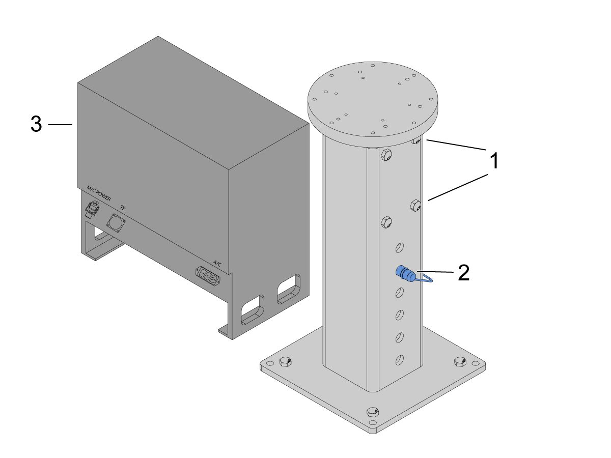
    받침대를 지면에 고정합니다. 버블 레벨을 사용하여 받침대의 수평을 맞춥니다.

    참고: 조정 가능한 받침대의 경우 고정 나사[1]를 푼 다음 클레비스 핀[2]을 조정하여 원하는 높이를 설정합니다. 로봇을 설치하기 전에 세트 스크루[1]를 다시 조입니다. 베이스에 (x4) 육각 볼트를 사용하여 X 및 Y 평면에서 레벨을 설정하는 동안 받침대 상단에 기포 수준기를 놓습니다.

    케이블이 충분히 느슨해지도록 코봇 제어 박스[3]를 받침대 바로 옆에 놓습니다. 

    6

    배송 상자에서 코봇을 제거합니다.

    참고: 필요한 경우 받침대와 로봇 사이에 어댑터 플레이트를 설치합니다.

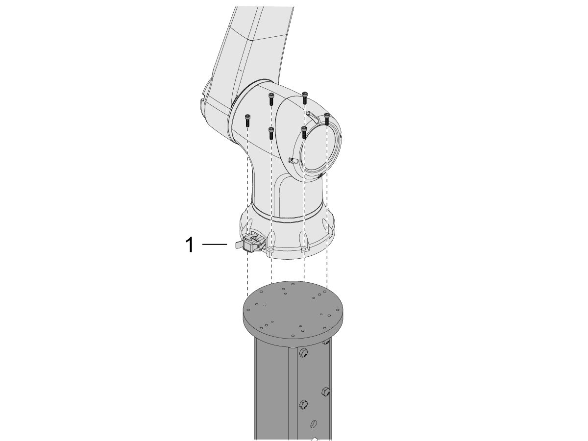
    (x6)개의 나사를 사용하여 받침대 상단에 코봇을 설치합니다.

    참고: 코봇 케이블 커넥터[1]가 기계 전면과 수직인지 확인하십시오. 

    중요: 코봇은 약 40lbs이며 해당 무게를 안전하게 들어 올릴 수 있는 장치로 들어 올려야 합니다.

    7

    코봇 패키징 내부에는 다음과 같은 예비 부품으로 채워진 작은 백[1]이 있습니다. 

    • 퓨즈
    • 나사 (x2)
    • 제어 박스 키

    여분의 M12 커넥터로 채워진 중간 크기의 백[2]이 있습니다. 이 케이블을 사용하여 End I/O 모듈의 입력 및 출력을 구성할 수 있습니다. 

    종이로 채워진 대형 백[3]과 코봇 소프트웨어로 다운로드한 USB 스틱이 있습니다.

    나중에 사용할 수 있도록 이러한 예비 부품을 안전한 곳에 보관하십시오. 

    Robot Electrical & Air - Installation

     DANGER: Working with the electrical services required for CNC machines is extremely hazardous and can result in serious injury or death.

    Before connecting line wires to the CNC:

    • Turn off all power to the machine at the source.
    • Perform a Lockout-Tagout (LOTO) procedure to ensure the power remains off during service.
    • Verify that power has been disconnected by using an AC voltage detector on all incoming lines.

    If you are uncertain about how to safely disconnect power or perform LOTO procedures:

    • Do not proceed.
    • Contact qualified personnel or obtain appropriate assistance before continuing.

    Failure to follow these precautions may result in electrical shock, equipment damage, or fatal injury.

     Danger: Before beginning any work inside the control cabinet, verify that the High Voltage indicator light on the 320V Power Supply / Vector Drive has been off for a minimum of five (5) minutes. This waiting period ensures that residual voltage has dissipated and reduces the risk of electric shock.

    Certain service procedures involve high-risk electrical components and may pose serious injury or fatality hazards. Technicians must not attempt any procedure unless they have a complete understanding of the steps involved and the associated risks.

    If there is any uncertainty regarding a procedure, contact your Haas Factory Outlet (HFO) to arrange for a qualified service technician.

    1

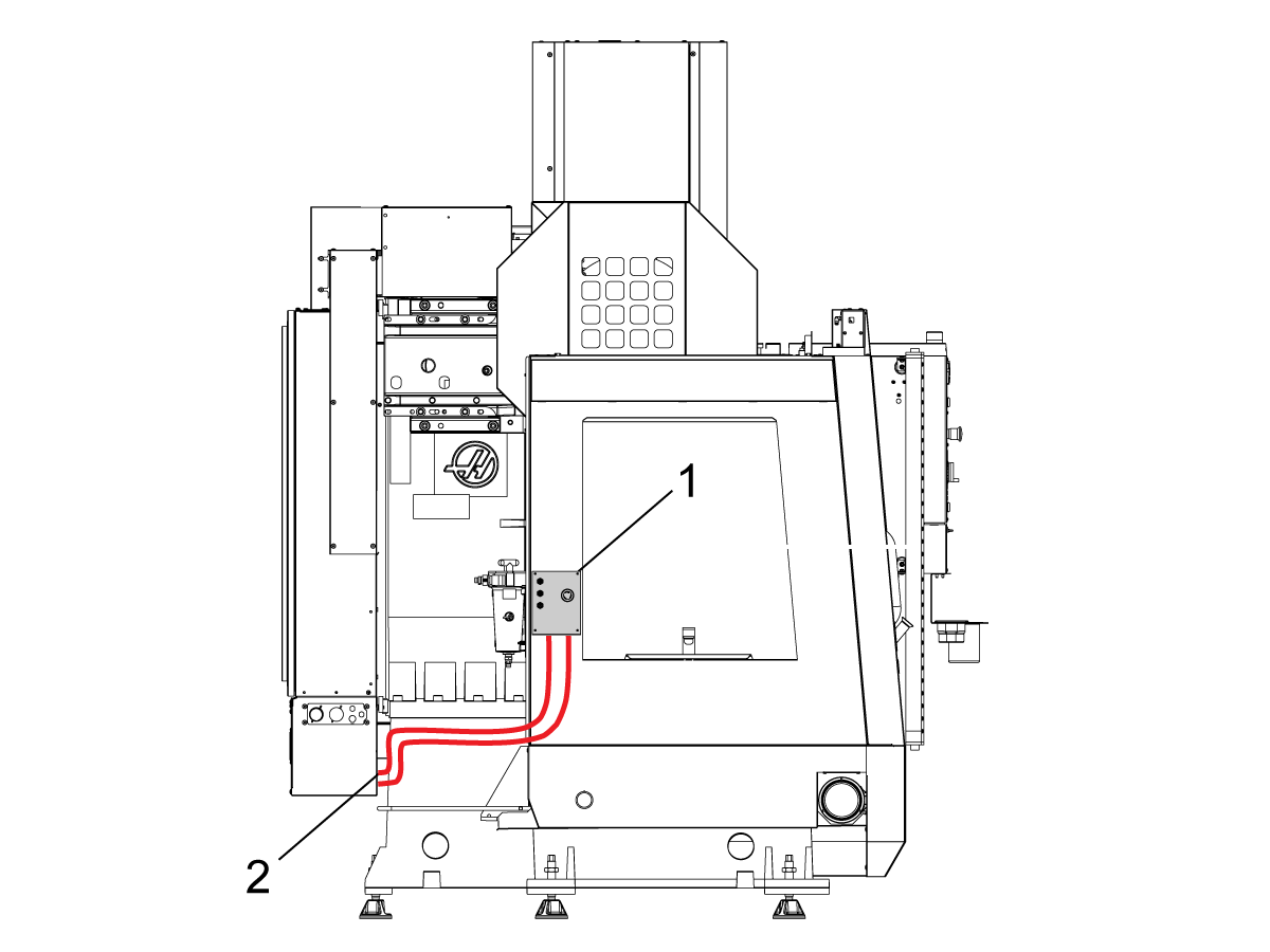
    인터페이스 박스를 Haas 기계에 연결합니다.

    로봇 안전 장치 인터페이스 상자 32-9018 에는 기계 판금에 부착할 수 있는 마그네틱 마운트가 있습니다. 그림과 같이 인터페이스 상자[1]를 장착하십시오.

    마그네틱 마운트와 집타이가 있는 인클로저를 따라 로봇 인터페이스 전기 케이블[2]을 배선합니다. 케이블을 전기 캐비닛 하단으로 배선합니다.

    참고: 인터페이스 상자를 로봇 안전 장치 인터페이스 박스로 업그레이드하는 방법에 대한 자세한 내용은 로봇 안전 장치 인터페이스 박스 - 설치 - AD0703을 참조하십시오. 

    2

    인터페이스 박스를 Haas 제어 캐비닛에 연결합니다.

    케이블 33-8562C 비상 정지 터미널 블록을 TB-1B [1]에 연결하고 설치 모드 터미널 블록을 SIO PCB의 TB-3B [1]에 연결합니다.  

    사용자 릴레이를 K9 및 K10[2]에 끼웁니다.

     점퍼가 JP1의 SIO PCB에 설치되어 있는지 확인하십시오.

     P1 SIO 로 표시된 피그테일 케이블을 P1 [3]에서 SIO PCB에 연결합니다.

    참고:  기계에 Regen 벡터 드라이브가 있는 경우, 케이블 33-0634 FILTER OV TO IOPCB P1을 P1 SIO에서 분리하고 케이블 33-8562C의 커넥터 FILTER OV FAULT에 꽂습니다. 기계에  재생 벡터 드라이브 가 없는 경우, 커넥터FILTER OV FAULT

    에 아무 것도 꽂지 마십시오.

     RJ-45 케이블 [4]을 이더넷 -USB 어댑터 [5] (33-0636) 에 연결하십시오.  USB 커넥터를 Maincon PCB J8  상단 포트에 연결합니다.페라이트 필터[6] 를 USB 어댑터에 추가합니다.

    24VDC 전원공급장치[7]를 제어 캐비닛의 왼쪽에 장착하고 24V PS 케이블에 33-8562C라고 표시된 커넥터에 꽂습니다. 케이블 33-1281 [8] 를 24VDC 전원공급장치[7]에 연결하고 PSUP PCB 

    의 P3 에 연결합니다.

    3

    XMR이 없는 MM/SMM CM/CL 기계의 경우

    P3가 PSUP PCB의 P3 [10]에서 P7 [9]로 연결된 점퍼에 의해 사용 중인 경우 24VDC 전원공급장치 [7]를 PSUP의 120VAC 커넥터에 연결하기 위해 스플리터 케이블이 필요합니다. 스플리터 케이블의 수 커넥터를 P3 [10]에 연결한 다음 해당 케이블의 점퍼를 P7 [9] 및 케이블 33-1281 [8]에 연결합니다.

    참고: 점퍼 케이블이 스플리터 케이블의 빨간색과 일치하는 위치에 연결되어 있는지 확인하십시오.

    4

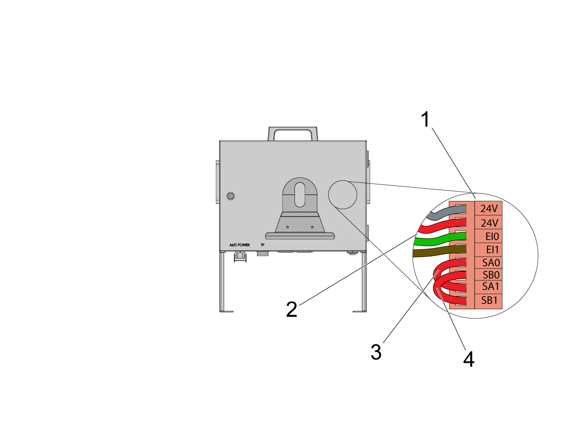
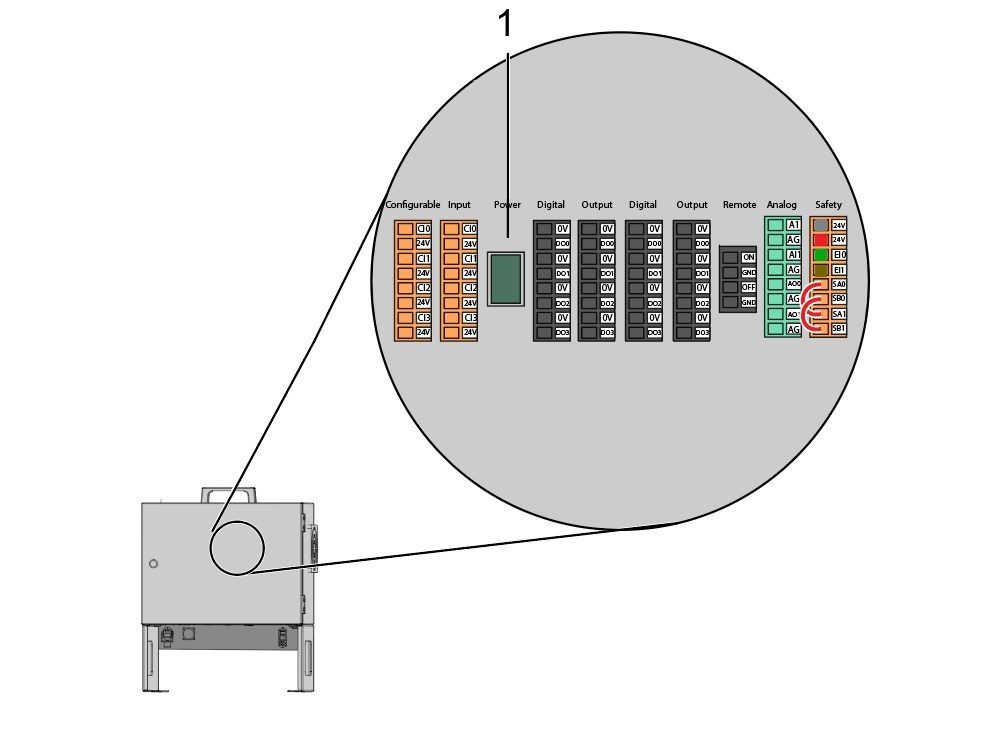
    코봇 제어 박스 내부에 로봇 신호 케이블 (33-1272 또는 33-1351)의 일부를 설치합니다.  이렇게 하려면 코봇 제어 박스에서 안전 커넥터 [1]를 제거하여 다른 색상의 전선을 각각의  위치

    에 설치하십시오. 안전 커넥터로 이어지는

    33-1272 / 33-1351 케이블[2]:

    • 회색 전선부터 상단 24V까지
    • 빨간색 전선부터 하단 24V
    • 까지
    • 녹색 전선부터 EI0까지
    • 갈색 전선부터 EI1까지
    • 점퍼[3]( SA0 ~ SA1
    • )
    • 점퍼 [4]( SB0 ~ SB1
    • )

     참고: 이 케이블의 나머지 전선은 사용되지 않습니다. 각 전선 리드에 전기 테이프를 놓고 사용하지 않은 나머지 와이어를 짚타이로 묶습니다. 

    5

    중요: 로봇 신호 케이블의 모든 케이블을 설치한 후 코봇 제어 상자를 보호하기 위해 퓨즈 [1]가 항상 설치되어 있는지 확인하십시오.

    6

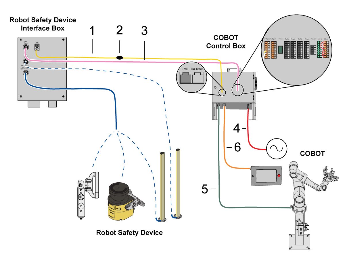
    코봇 을 인터페이스 박스에 연결합니다.

    RJ45 이더넷 케이블 [1]을 코봇 제어 박스에서 인터페이스 박스로 연결합니다. 페라이트 필터[2]를 RJ-45 케이블에 추가합니다.

    로봇 신호 케이블[3]을 코봇 제어 박스에서 인터페이스 박스로 연결합니다. 

    120VAC 코봇 전원 케이블[4]을 외부 전원에 연결하십시오. 

    로봇 전원 케이블 [5]을 제어 박스에서 코봇으로 연결합니다.

    제어 박스의 교육 펜던트 케이블 [6]을 교육 펜던트에 연결합니다. 

    참고: 인터록 펜스, 영역 스캐너 또는 광 커튼 설치에 대한 자세한 내용은 아래 로봇 안전 장치 섹션을 참조하십시오.

    7

    원격 조그 핸들이 기계에 설치되어 있는지 확인하십시오.

    참고: RJH-XL 설치에 대한 자세한 내용은 원격 작업 핸들 - Touch Large(RJH-XL) - 설치 - AD0533을 참조하십시오. 

    8

    7 ~ 10 단계는 공압 그리퍼의 배선 및 호스 배선 지침입니다. 기계적 설치는 이 페이지의 하단에 있는 그리퍼 설치 섹션을 참조하십시오.

    에어 라인이 충분히 느슨해지도록 하면서 듀얼 에어 솔레노이드 어셈블리를 받침대 측면에 설치하십시오. 간섭되지 않는 위치에 있는지 확인하십시오. 그림과 같이 기계 아래의 에어 라인 [1]을 CALM 캐비닛 쪽으로 다시 배선합니다.

    9

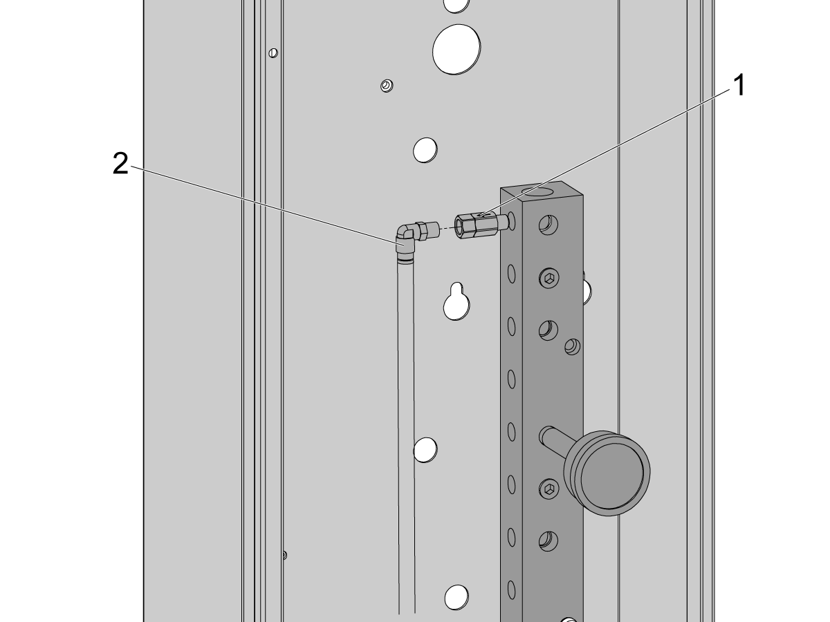
    CALM 캐비닛 내부의 CALM 매니폴드 포트 중 하나에서 플러그를 제거하고 포트의 피팅에 체크 밸브 [1](58-1863)를 설치합니다. 듀얼 에어 솔레노이드 어셈블리(이전 단계에서)에서 CALM 캐비닛으로 입력 에어 라인 [2]을 배선하고 에어 라인을 체크 밸브에 연결합니다.

    기계 공기 공급 장치를 켜십시오.

    10

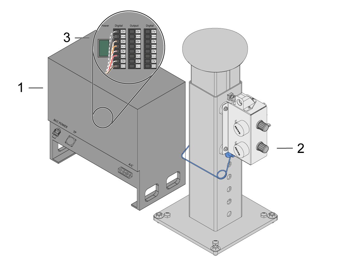
    제어 박스 [1]의 동력을 끄십시오.

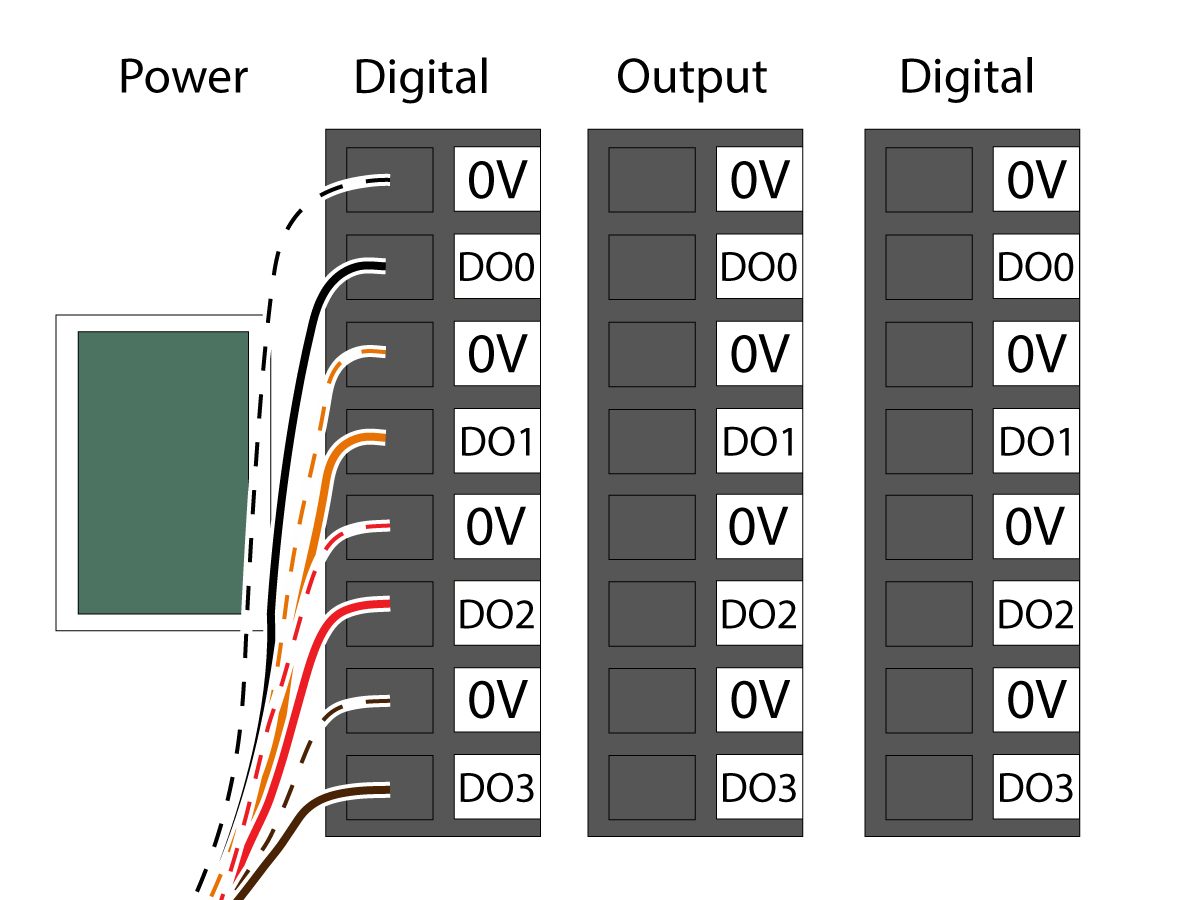
    솔레노이드 케이블을 듀얼 에어 솔레노이드 어셈블리 [2]에서 코봇제어 박스 [1]의 Digital Output(디지털 출력)에 연결합니다. 코봇 제어 박스에서 커넥터를 제거하십시오.

    11

    그리퍼 솔레노이드 전원 케이블 (33-1276 / 33-1341)을  제어 박스 내부의 디지털 출력 단자에 연결합니다. 다른 색상의 전선을 각 위치에 설치합니다.

    • 0V에 검정색/흰색 케이블 연결
    • DO0 에 검정색 케이블 연결
    • 0V에 주황색/흰색 케이블 연결
    • DO1에 주황색 케이블 연결
    • 0V에 빨간색/흰색 케이블 연결
    • DO2에 빨간색 케이블 연결
    • 0V에 갈색/흰색 케이블 연결
    • DO3에 갈색 케이블 연결

    제어 박스의 동력을 켭니다.

    Robot Safety Device

    중요: 안전 장치의 작동을 올바르게 구성하고 테스트할 때까지 로봇을 작동하지 마십시오.

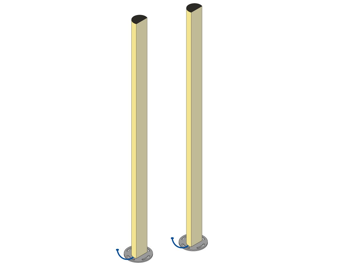
    광 커튼

    코봇 패키지는 광 커튼 송신기 및 리시버와 함께 기본 안전 장치로 제공됩니다. 광 커튼은 아래 절차에 따라 설치하십시오. 

    광 커튼 설치

    참고: 영역 스캐너 또는 HC10 기계 준비 키트를 주문한 경우 1M 광 커튼 수신기 및 송신기도 있습니다. 모든 코봇에 함께 제공됩니다.

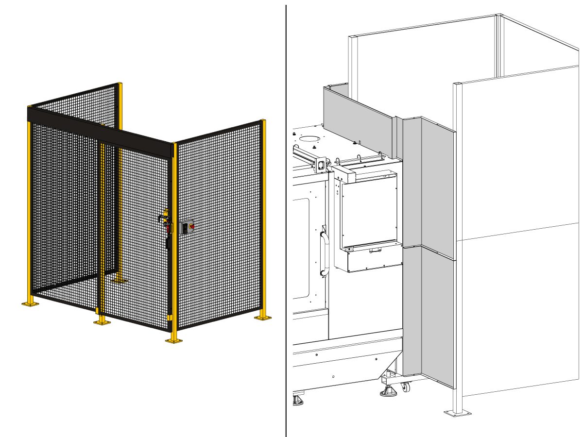
    로봇 펜스:

    기계에 펜스 옵션이 장착된 경우 기계에 로봇 펜스 및 도어 인터록 어셈블리를 설치해야 합니다. 아래 절차에 따라 설치하십시오.

    로봇 펜스 설치

    펜스가 설치되면 기계와 로봇 펜스 사이에 펜스 패널을 설치합니다.

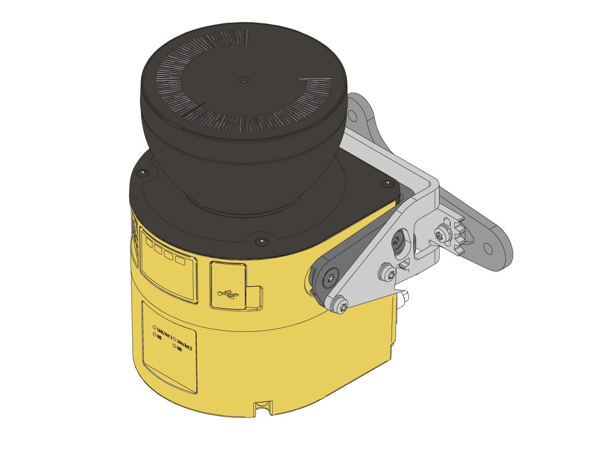
    영역 스캐너

    기계에 영역 스캐너 옵션이 장착된 경우, 영역 스캐너를 공간에 설치하고 구성해야 합니다. 아래 절차에 따라 설치하십시오. 

    영역 스캐너 설치

    First Power-UP

    1

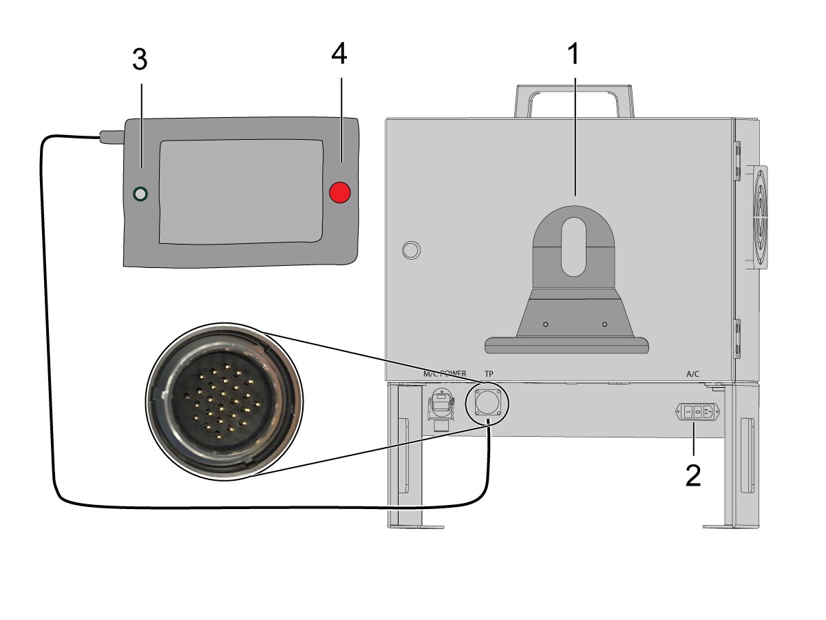
    코봇 제어 박스 전면에 교육 펜던트 홀더[1]를 설치합니다. 

    Haas 기계를 켜십시오. 

    전원 스위치[2]를 뒤집어서 코봇 제어 박스의 전원을 켭니다.

    원 [3]을 눌러 코봇 교육 펜던트의 전원을 켭니다. 

    코봇 교육 펜던트의 비상 정지[4]가 해제되어 있는지 확인합니다. 

    2

    참고: 코봇 교육 펜던트에는 사용자 이름과 암호를 입력하라는 팝업이 표시됩니다. 교육 펜던트에 로그인하려면 다음 자격 증명을 사용하십시오.

    • 사용자 이름 = admin
    • 암호 = admin

    실행 모드로 들어갑니다. 활성화를 누르십시오. 

    조그 모드[1]로 들어갑니다.

    영점 이동 버튼[2]을 사용하여 각 조인트를 영점 위치로 이동합니다. 

    3

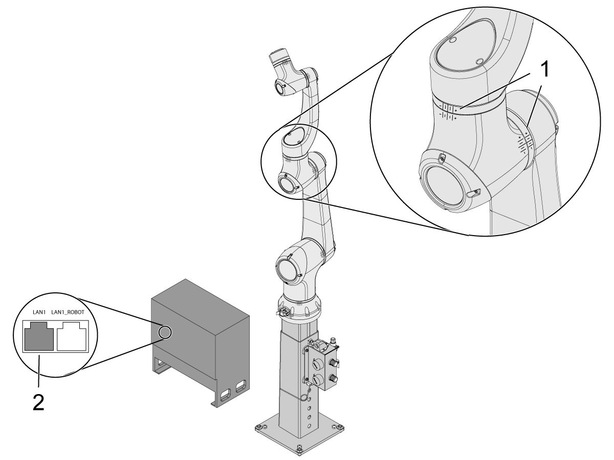
    로봇이 영점 위치에 있으면 해시 라인[1]이 코봇의 각 조인트 양쪽에 정렬되었는지 확인합니다. 

     중요: 조인트 해시 라인[1]이 정렬되지 않으면 모든 해시 라인[1]이 정렬될 때까지 특정 조인트를 적절히 조그합니다. 이 위치는 다음 단계에서 새 코봇 영점 위치로 설정됩니다.  

    이더넷 케이블[2]을 코봇 제어 박스에서 컴퓨터로 연결합니다.

    컴퓨터에서 어댑터 설정을 변경하여 이더넷 포트를 활성화합니다. 

    참고: 어댑터 설정 변경에 대한 도움말은 다음 단계를 참조하십시오.

    4

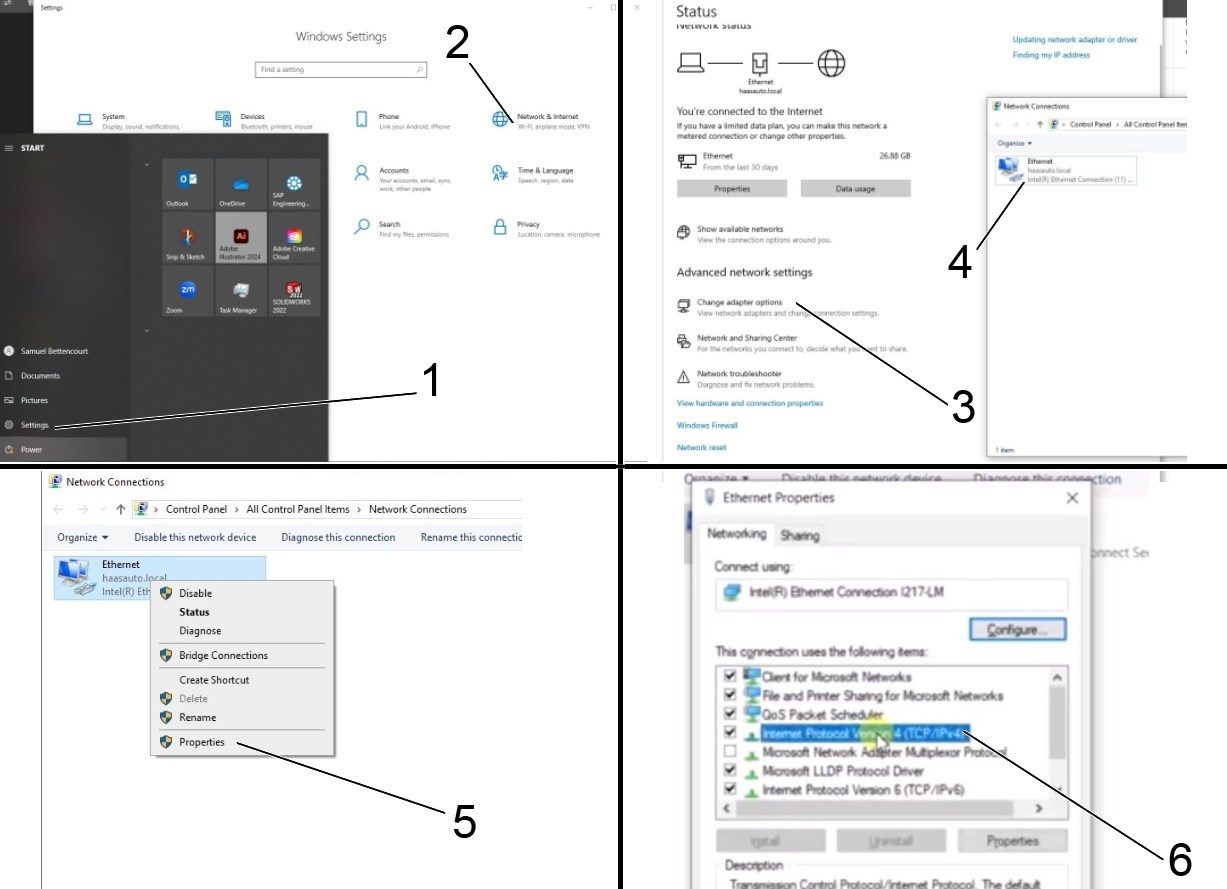
    어댑터 설정을 변경하려면 컴퓨터에서 설정 페이지 [1]를 연 다음 네트워크 및 인터넷 [2]을 클릭하면 네트워크 상태 페이지가 나타납니다.

    어댑터 옵션 변경[3]을 클릭한 다음 이더넷[4]을 마우스 오른쪽 버튼으로 클릭하고 속성 창[5]을 엽니다. 여기서 인터넷 프로토콜 버전 4(TCP/IPv4) [6] 옵션을 선택하고 확인을 클릭합니다. 


    5

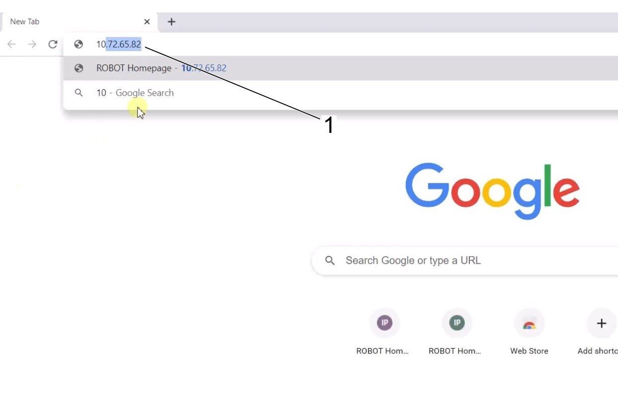
    이제 이더넷 설정이 정확합니다. 웹 브라우저 창을 열고 코봇[1]의 IP 주소를 입력하십시오. 

    참고: 이는 노트북을 HRP-1/2/3에 연결하는 것과 동일한 프로세스입니다. 이더넷을 통한 코봇 연결에 대한 추가 정보는 Haas 로봇 연결 및 조그 섹션에 있는 HRP-문제 해결 페이지의 동영상을 참조하십시오. 

    6

     HBC에서 HRTool을 다운로드합니다. HBC의 서비스 섹션에서 Utilities(유틸리티) > Documents and Software(문서 및 소프트웨어) > 01 Control Software(제어 소프트웨어) > 01 Next(다음) Generation Control(생성 컨트롤) > 10 Cobot Software(10 코봇 소프트웨어) > HRTool.zip으로 이동합니다.

    폴더의 압축을 풀고 HRToolsMaind.exe로 이동합니다.

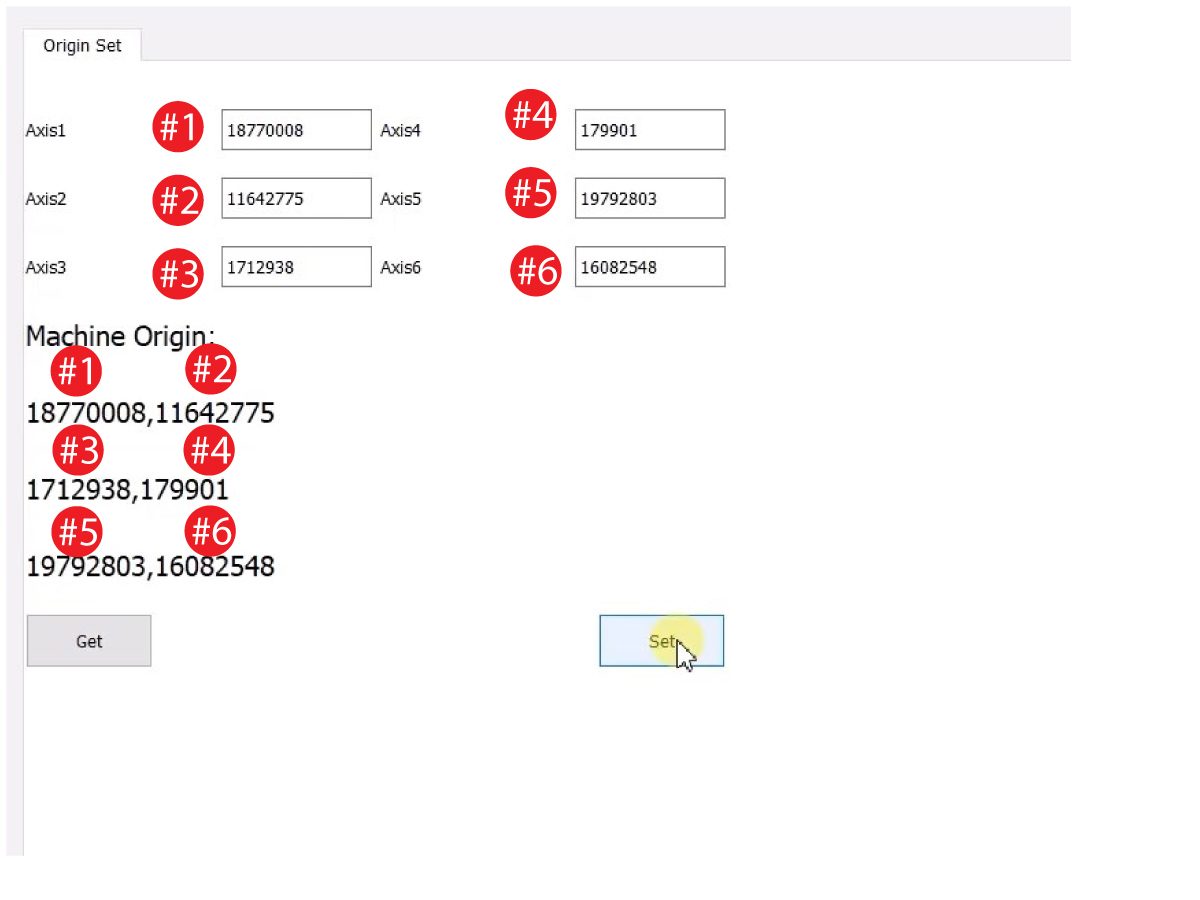
    시스템 탭 아래에 있는 코봇 IP 주소를 입력합니다.  Set(설정)을 클릭합니다. 

    HRTool의 Config(구성) 탭으로 이동합니다.

    실제 인코더 값과 이론적 인코더 값을 보려면 "get"을 클릭하십시오. 

    "set"을 클릭하여 이론적인 인코더 값을 실제 인코더 값으로 설정하십시오. 이 단계는 코봇의 현재 위치를 새 원점 위치로 설정합니다. 

    7

    각 조인트의 실제 인코더 값과 이론적 인코더 값이 일치하는지 확인하십시오. 

    참고: 값이 일치하지 않으면 "Set(설정)"을 다시 누르십시오. 

    8

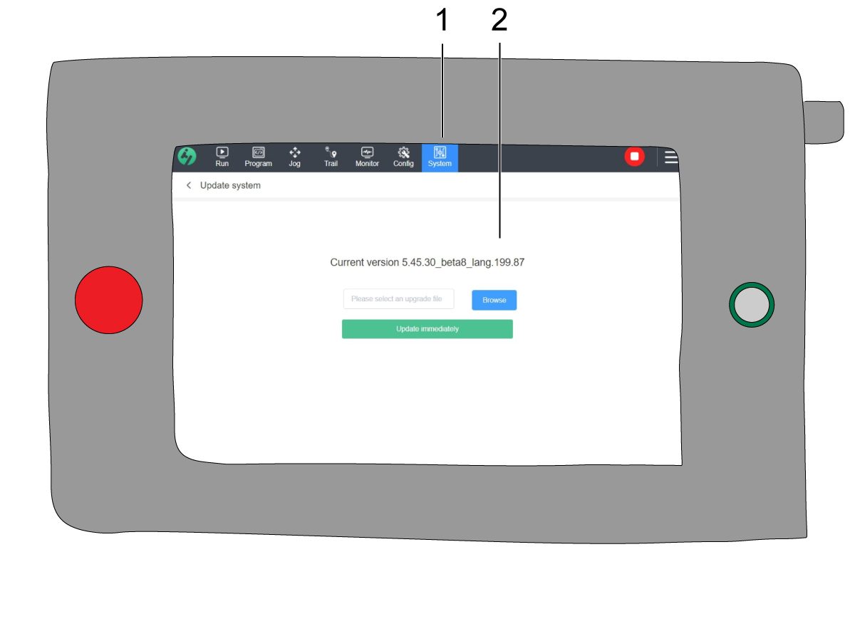
    교육 펜던트에서 시스템[1]으로 이동한 다음 시스템 업데이트로 이동합니다. 

    코봇 펌웨어[2]가 다음 중 하나인지 확인합니다.

    • HR5.51H.16.beta.20231213.zip
    • HR6.4.9.tmp.20240919.zip

    참고: 펌웨어 버전 HR6.4.9.tmp.20240919.zip 은 모든 크기의 코봇과 호환됩니다.

    펌웨어 업데이트 절차는 Haas 코봇 - 유지보수  장을 참조하십시오. 

    9

    Haas 펜던트에서 모든 축을 영점 복귀합니다.

    서비스 USB 키를 삽입하십시오.  서비스 모드로 들어갑니다.

    Parameters> Factory 탭으로 이동합니다.  다음을 변경합니다.

    • 1278 [1278 :] Robot Ready E-Stop Enabled를 TRUE로
    • 2191 [694 :] 광 거튼 유형을 LC_TYPE_1
    • 로
    • 2195 [:] 오른쪽 도어를 완전히 열기 스위치를  TRUE
    • 로 켭니다
    • 2196 [:] 왼쪽 도어를 완전히 열기 스위치 를 TRUE로 켭니다
    • 2192 [:] 광 커튼 트리거 임계치를   0으로

    [SETTING]을 누릅니다.

    설정을 다음과 같이 지정합니다.

    • 372 Parts Loader Type을  3: Robot으로.
    • 376 Light Curtain Enabled를 On
    • 으로

    10

    Haas 펜던트에서 [CURRENT COMMANDS]를 누릅니다.

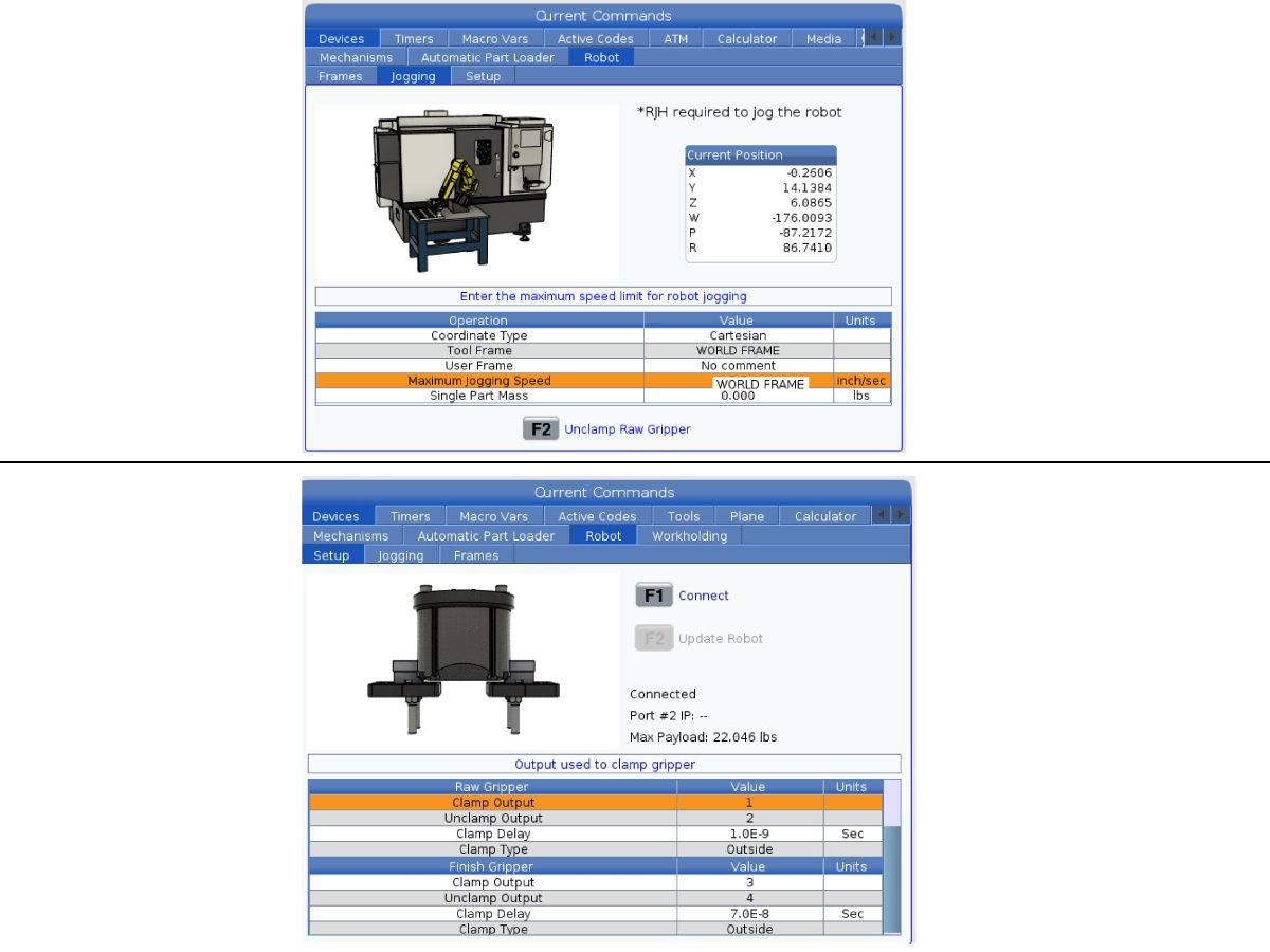
     장치>로봇>조깅  탭으로 이동하여 다음과 같은 사항을 변경합니다.

    • Maximum Jogging Speed를 7.9  inch/sec
    • 로

     참고: RJH의 조깅 증분값은 이 최대 속도 값의 백분율입니다. 각 조그 휠의 로봇 이동 거리를 줄이려면 최대 조깅 속도 를 더 낮은 값으로 변경해야 합니다.

    Setup  탭으로 이동합니다. 다음과 같은 사항을 변경합니다.

    • Max Robot Speed(최대 로봇 속도를 2000mm/sec(118in/sec)로 
    • 설정합니다.
    • 그리퍼의 Net Mass(순 질량)을 입력합니다. 이 설정에 대한 올바른 값을 얻으려면 당사 웹사이트의 레이아웃 도면(단일 그리퍼 레이아웃 도면 또는 듀얼 그리퍼 레이아웃 도면)을 참조하십시오
    경고: 이 값을 잘못 설정하면 로봇 암이 올바르게 움직이지 않을 수 있습니다. 
     
    • Number of Grippers를 그리퍼의 수로
    • Raw Gripper Clamp Output(공작물 그리퍼 클램프 출력)을 1
    • 로
    • 공작물 그리퍼 클램프 해제 출력(Raw Gripper Unclamp Output) 을 2로.
    • 공작물 그리퍼 클램프 지연을 클램프/클램프 해제 지속 시간(초)으로 변경합니다.
    • Raw Gripper Clamp Type 을 OD/ID로
    • 마감 그리퍼 클램프 출력(Finish Gripper Clamp Output) 을 3으로.
    • 마감 그리퍼 클램프 해제 출력(Finish Gripper Unclamp Output) 을 4로.
    • Finish Gripper Clamp Delay 를 클램프/클램프 해제 지속 시간(초)로 
    • Raw Gripper Clamp Type 을  OD/ID로

    교육 펜던트 끄기

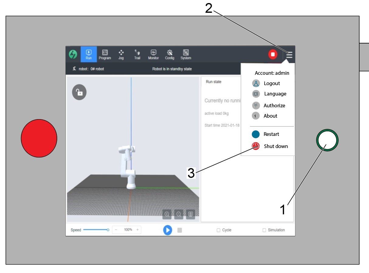
    경고: 교육 펜던트의 전원 버튼[1]을 사용하여 종료하지 마십시오. 이렇게 하면 코봇 제어 박스 내의 시스템 파일이 손실될 수 있습니다.

    교육 펜던트의 전원을 끄려면 오른쪽 상단 모서리[2]에 있는 3개의 라인을 눌러 오른쪽에 있는 옵션 메뉴를 불러옵니다.

    종료 옵션[3]을 선택하여 코봇 제어 박스의 전원 끄기 시퀀스를 시작합니다.

    중요: 교육 펜던트를 잘못 끄면 코봇 제어 박스의 중요한 파일이 손상될 수 있습니다. 이렇게 하면 시스템 파일이 제어 박스에 다시 설치될 때까지 코봇을 사용할 수 없게 될 수 있습니다.


    Security Risk Level

    1

    중요: 적절한 위험 평가를 수행하고 모든 적절한 안전 요구 사항을 충족했는지 확인하십시오. 

    2

    위험 평가를 기반으로 코봇 교육 펜던트에서 적절한 보안 위험 수준을 설정하십시오. Config(구성) > General Restrictions(일반 제한사항)로 이동하고 0~5까지 원하는 보안 위험 수준[1]을 탭하십시오.

    안전 검증에서  "admin

    " 코드를 사용하여 보안 레벨을 변경하십시오.

    참고: 보안 위험 수준이 낮으면 로봇의 최대 속도, 힘 등이 낮아집니다. 보안 위험 수준이 높으면 로봇의 최대 속도, 힘 등이 더 높아집니다. 

    이 보안 위험 수준은 경보 경보 9150.10017

    충돌 정지 오류가 트리거되기 전에 코봇이 견디게 되는 최대 허용 가능 힘, 속도, 동력, 모멘텀, 엘보우 속도 및 엘보우 힘[2]을 계산합니다. 

    중요: 로봇의 프로그래밍된 속도는 보안 위험 수준에서 허용 가능한 속도보다 클 수 없습니다. 

    참고: 경보에 대한 자세한 내용은 Haas 코봇 - 문제 해결 안내서를 참조하십시오. 

    Activation

    1

    Haas Service 포털로 이동하여 구성 파일을 다운로드하십시오.

    안전 자동화 옵션 전면/측면 구성 파일을 다운로드합니다.

    옵션 구성 패치 파일을 제어 장치에 로드하십시오. 차세대제어장치 - 구성 파일 - 다운로드/로드절차를 참조하십시오.

    2

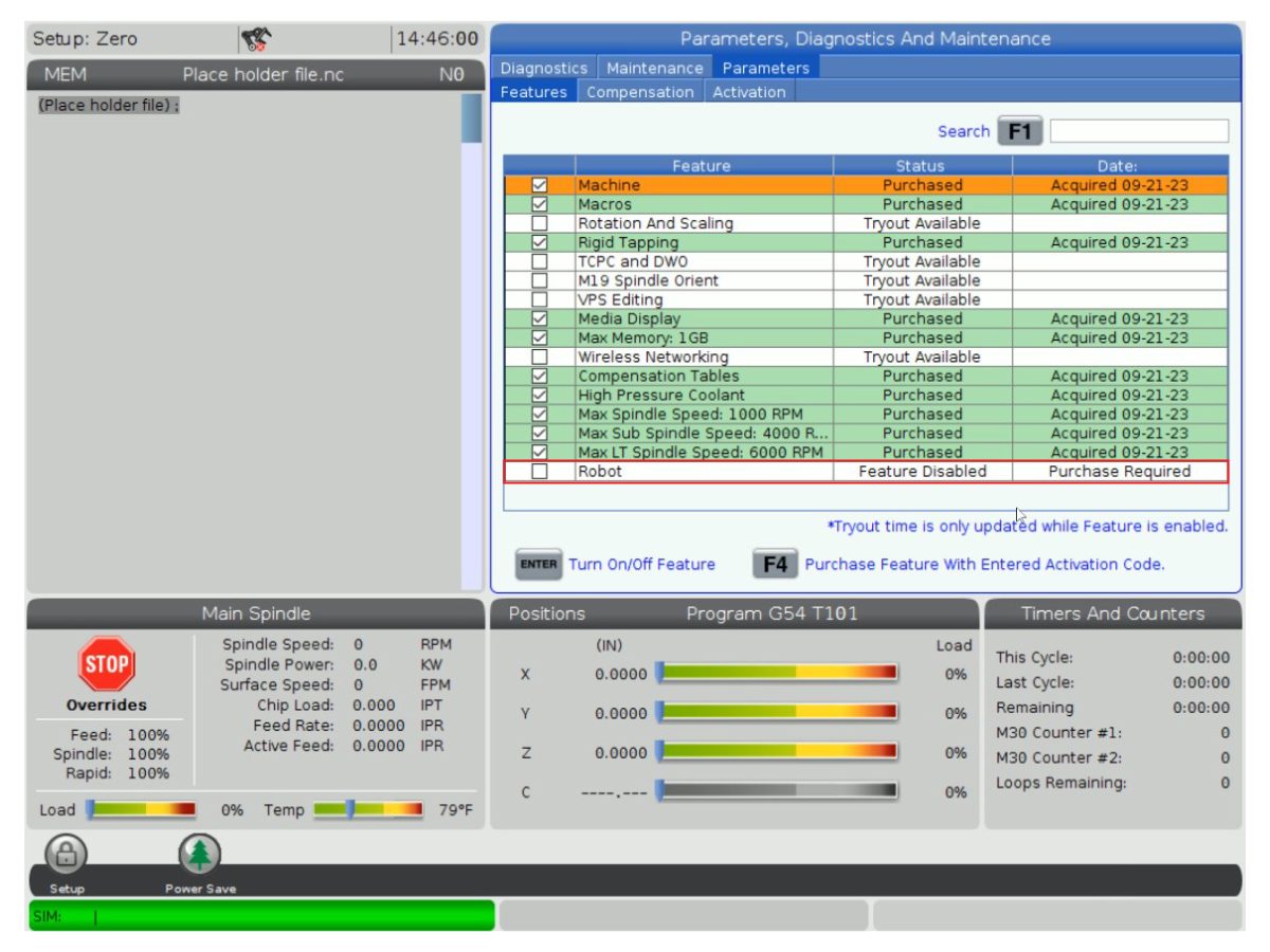
    Parameters(파라미터) > Features(기능) > Robot(로봇) 으로 이동하여 로봇 기능이 하단에 나타나는지 확인합니다.

    3

    [POWER OFF]을 누르십시오.

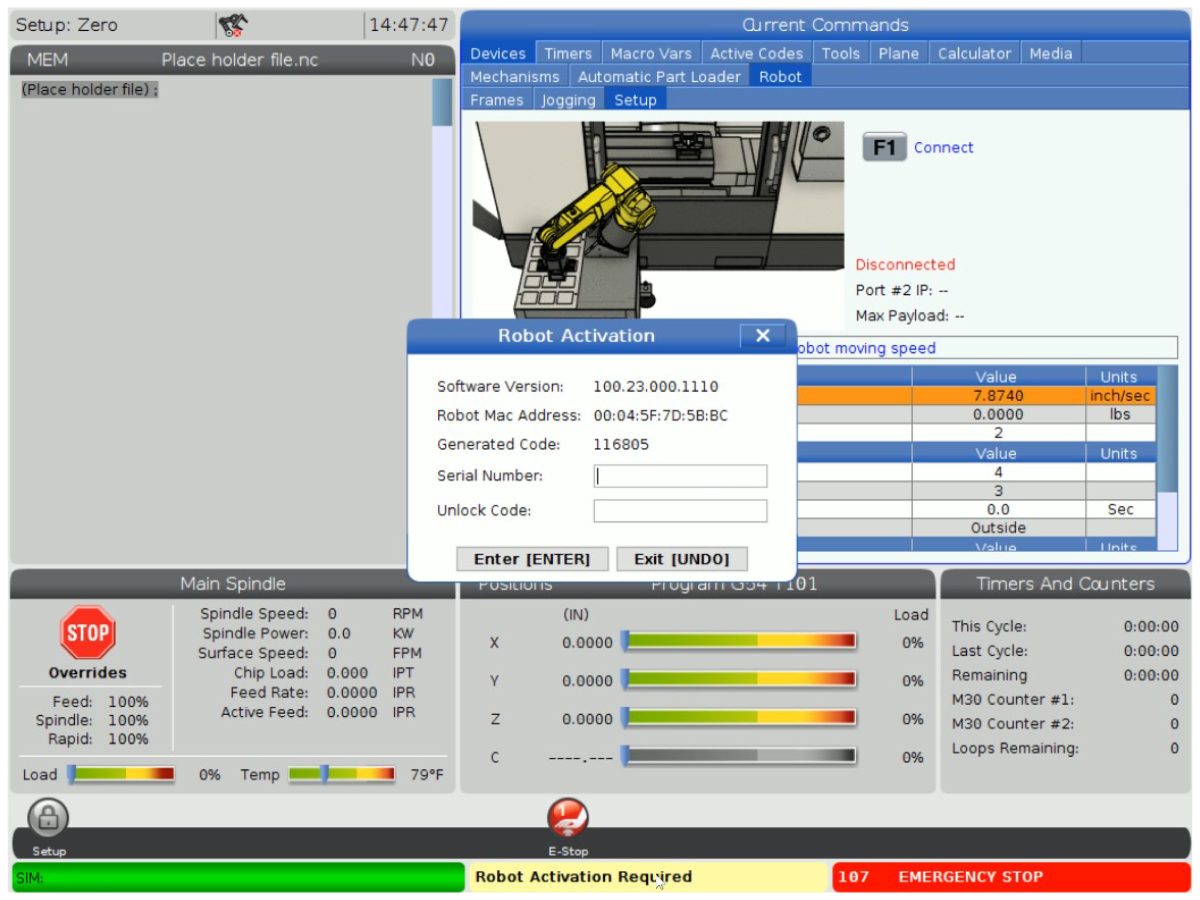
    Devices(장치)>Robot(로봇)>Setup(설정) 탭[1]으로 이동합니다.

    [E-Stop]을(를) 누르십시오.

    [F1]을 눌러 로봇[2]을 연결합니다.

    로봇을 기계에 처음 연결하면 로봇 기능을 잠금 해제해야 합니다. 이 팝업은 기계의 현재 소프트웨어 버전, 로봇 MAC 주소 및 생성된 코드를 보여줍니다. 잠금 해제 코드를 받으려면 이 정보를 HBC에 입력하십시오.

    4

    HBC에서 Service

    탭[1]으로 이동합니다.

    화면 왼쪽에서 Activations(활성화)[2]를 클릭한 다음 Cobot Installation(코봇 설치) [3]를 선택하여 코봇 잠금 해제 코드를 얻는 프로세스를 시작하십시오.

    첫 번째 단계는 HBC의 필드에 기계 일련 번호[4]와 코봇 일련 번호[5]를 입력하는 것입니다.

    올바른 정보를 입력했으면 오른쪽 하단 모서리에 있는 Next

     [6]를 누르고 잠금 해제 코드를 받을 때까지 단계를 계속하십시오.

    참고: Robot Installation(로봇 설치) 탭이 아닌 Cobot Installation(코봇 설치) 탭[3]인지 확인하십시오. 로봇 설치는 Haas 로봇 패키지에만 사용됩니다. Haas 코봇에 로봇 설치를 사용하면 유효하지 않은 잠금 해제 코드가 발생합니다.

    5

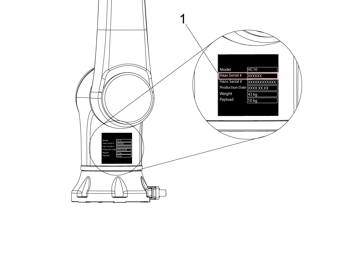
    코봇의 Haas 일련 번호

    [1]와 잠금 해제 코드를 입력하여 로봇을 기계에 연결합니다. 

     참고: 이 단계는 HFO 서비스 기술자만 완료할 수 있습니다.

     참고: 로봇이 활성화되기 전에 기계를 활성화해야 합니다. 기계 활성화/시간 연장 - NGC 절차를 따르십시오.

    로봇이 기계와 연결되면 노란색의 로봇 활성화 성공 메시지가 Haas 화면 하단에 나타납니다.

    6

    [E-STOP] 을 해제하고 RESET 을 눌러 경보를 소거합니다. 

    [HANDLE JOG]버튼을 누르십시오. 

    [CURRENT COMMANDS] 를 누르고 Devices > Robot > Jogging 탭으로 이동합니다.

     참고: 설정 모드의 로봇은 RJH를 누른 상태에서 F2 버튼을 누르고 있는 동안에만 조깅할 수 있습니다. 아래의 설정/실행 모드 섹션을 참조하십시오.

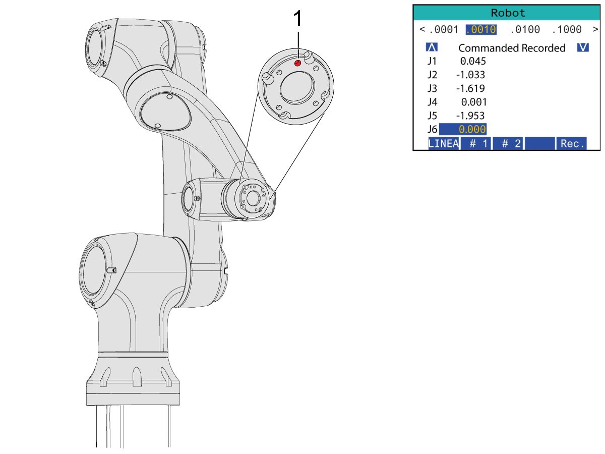
    Remote Handle Jog Touch에서 Joint 버튼을 눌러 Joints Coordinates로 이동합니다.

    그리퍼를 설치하려면 로봇을 적당한 위치로 옮기십시오.

    J6를 0.0000 위치로 조그합니다.

    위치 구멍은 상단 중앙에 있어야 합니다.

    참고 : 로봇에서 작업하기 전에 [Emergency Stop]을 누릅니다.

    Gripper Installation

    1

    공기/윤활 캐비닛에서 밸브를 돌려 기계 공기를 끄고 압력 해제 밸브를 당겨 시스템에 있는 공기를 방출하십시오.

    2

    듀얼 액션 그리퍼의 경우:

    이 섹션에는 두 가지 버전의 듀얼 액션 그리퍼가 있으며 둘 다 설치 프로세스가 동일합니다.

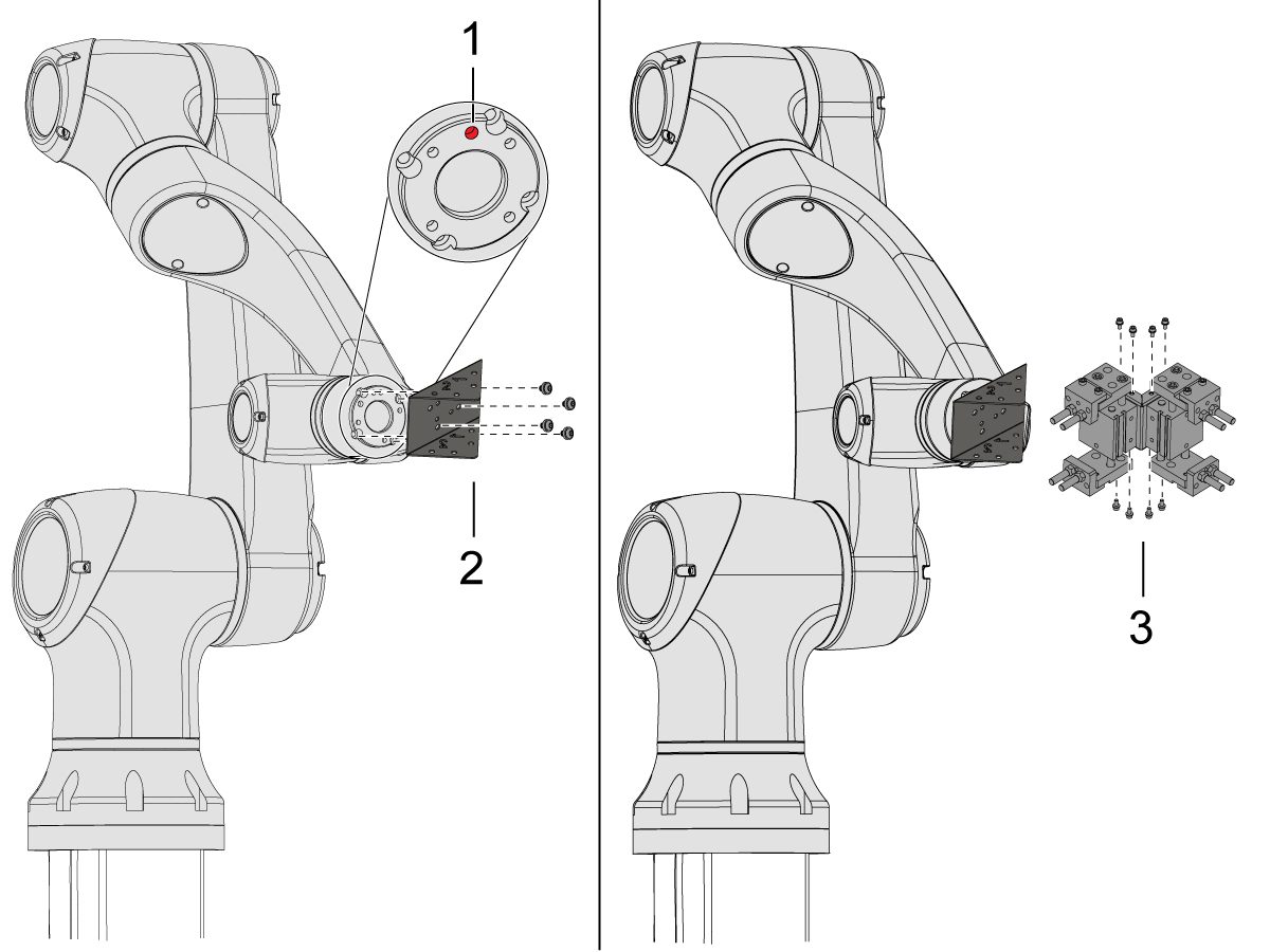
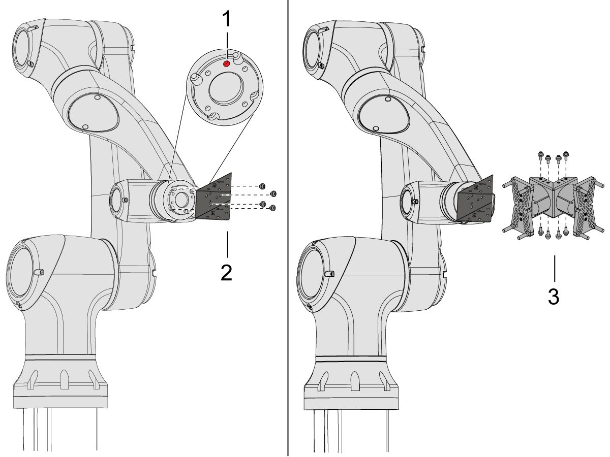
    위치 구멍 [1]이 상단 중앙에 오도록 로봇을 조그합니다.

    어댑터 플레이트 [2]를 로봇 암 끝에 설치합니다.

    듀얼 그리퍼 어셈블리 [3]를 어댑터 플레이트 [2]에 설치합니다.

    참고: 그리퍼 1 어댑터 플레이트 섹션에 그리퍼 1(오렌지색 및 자주색 케이블 타이가 있음)을 설치해야 합니다. 

    3

    앵글형 싱글 액션 그리퍼의 경우:

    위치 구멍 [1]이 상단 중앙에 오도록 로봇을 조그합니다.

    앵글 어댑터 플레이트 [2]를 로봇 암 끝에 설치합니다.

    단일 그리퍼 어셈블리 [3]를 앵글 어댑터 플레이트 [2]에 설치합니다.

    4

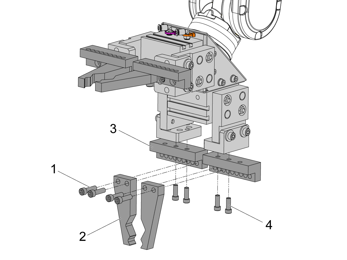
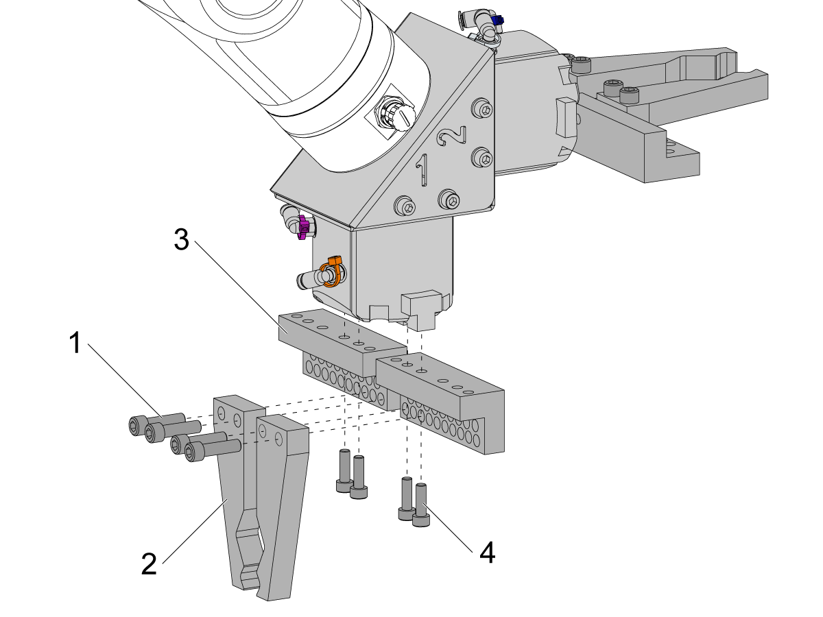
    바 그리퍼 핑거를 설치하려면 그리퍼 본체에서 슬러그 그리퍼 플레이트를 제거하십시오.

    SHCS M6 나사 (x8) [4]로 환봉 그리퍼 볼트 플레이트 [3]를 설치합니다. 10ft-lbs의 토크로 조입니다.

    SHCS 1/4-20 (x8) [1]을 사용하여 환봉 그리퍼 핑거 [2]를 설치합니다. 13 ft-lbs의 토크로 조입니다.

    5

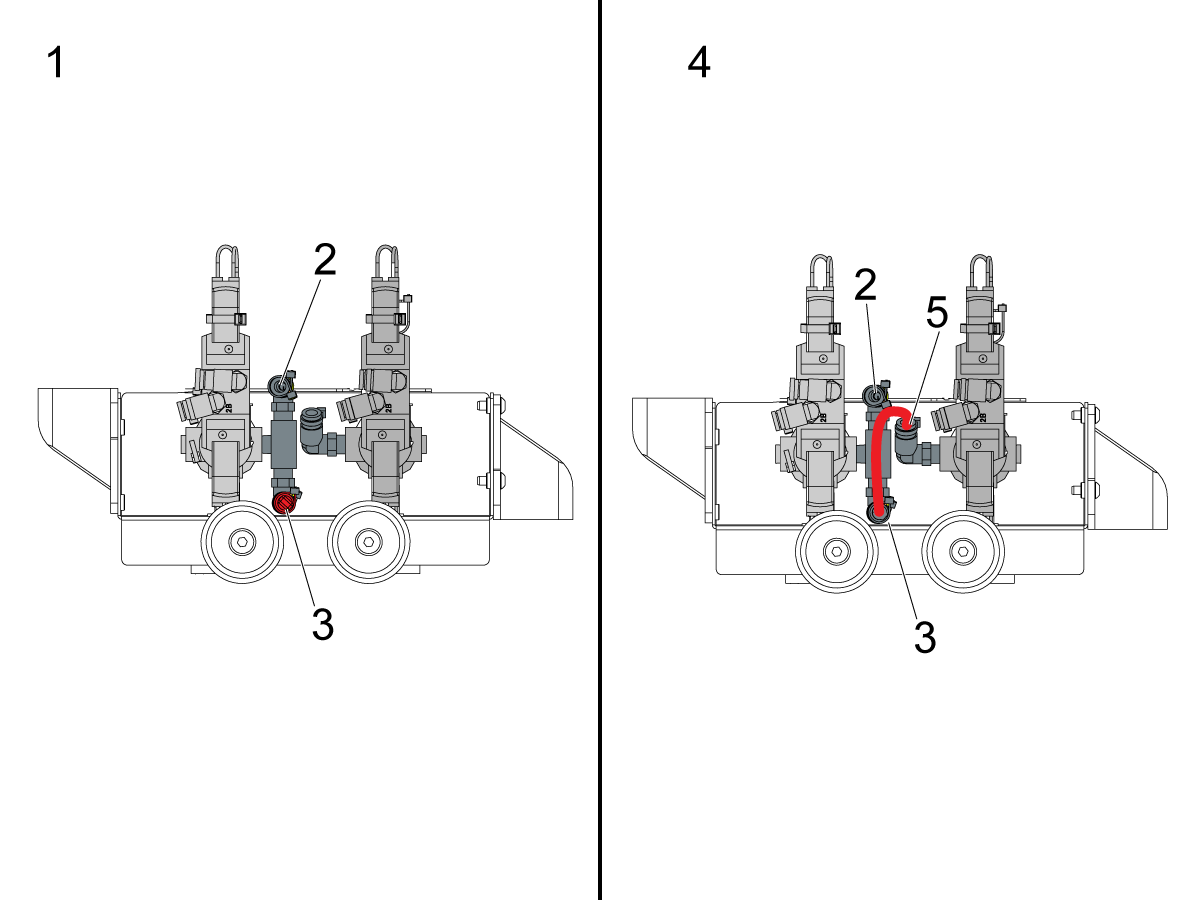
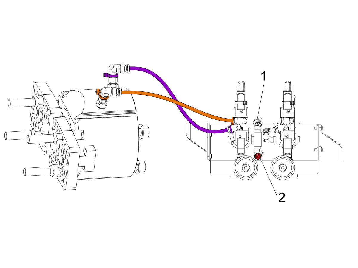
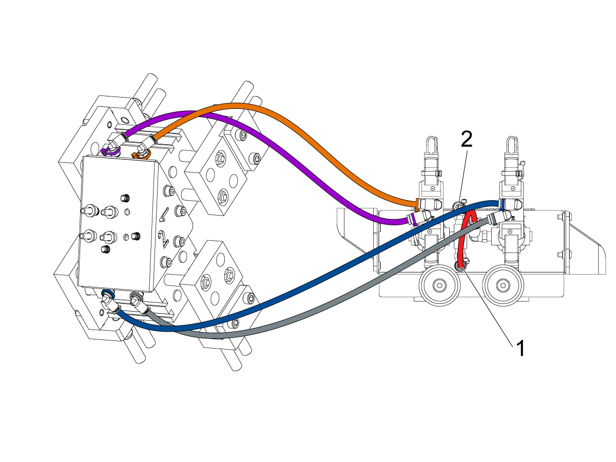
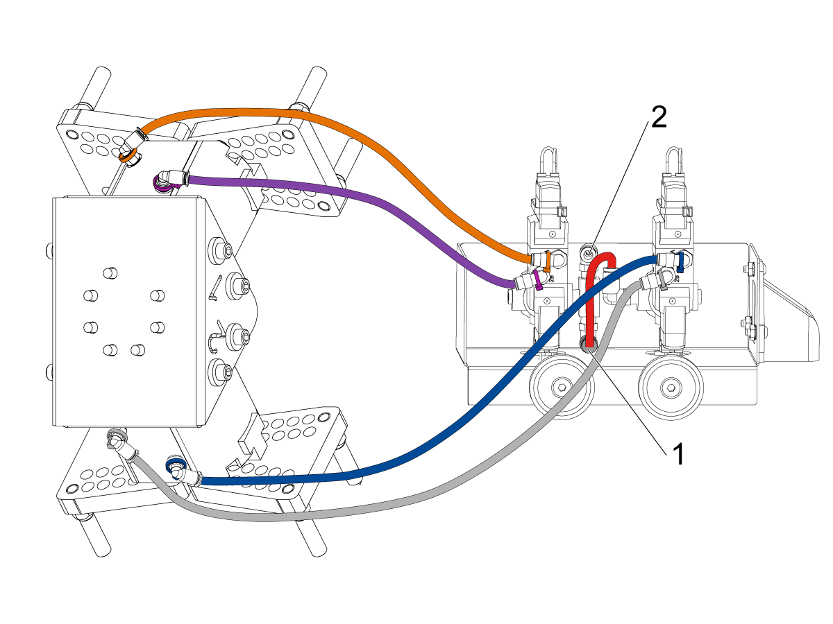
    단일 [1] 또는 듀얼 [2] 그리퍼 구성에 따라 공압 그리퍼에 사용되는 듀얼 에어 솔레노이드 어셈블리를 구성하십시오. 

    단일 그리퍼[1]의 경우, 들어오는 공기를 피팅[2]에 연결하고 그림과 같이 플러그를 피팅[3]의 다른 쪽 끝에 플러그를 꽂습니다.

    듀얼 그리퍼 [4]의 경우 피팅 [3]의 플러그를 제거하고 작은 에어 호스를 두 번째 솔레노이드 [5]에 부착합니다. 그런 다음 두 솔레노이드에 공기가 공급되도록 인입 에어 호스를 피팅 [2]에 연결하십시오.

    6

    단일 그리퍼의 경우:

    그리퍼에서 듀얼 에어 솔레노이드 어셈블리의 동일한 색상 코드 피팅으로 (x2) 에어 라인을 배선합니다. 

    케이블 도관에 에어 라인을 감아 고정합니다. 벨크로 스트랩을 사용하여 케이블 도관을 코봇에 부착합니다. 코봇이 완전히 확장될 때 케이블이 변형되지 않도록 충분히 느슨한지 확인하십시오.

    에어 주입 호스를 사용한 솔레노이드 피팅[1]에 삽입하십시오. 

    플러그가 사용하지 않는 솔레노이드 피팅 [2]에 설치되어 있는지 확인하십시오. 

    7

    듀얼 그리퍼의 경우:

    그리퍼 #1에서 듀얼 에어 솔레노이드 어셈블리의 동일한 색상 코드 피팅으로 (x2) 에어 라인을 배선합니다. 

    그리퍼 #2에서 듀얼 에어 솔레노이드 어셈블리의 동일한 색상 코드 피팅으로 (x2) 에어 라인을 배선합니다. 

    케이블 도관에 에어 라인을 감아 고정합니다. 벨크로 스트랩을 사용하여 케이블 도관을 코봇에 부착합니다. 코봇이 완전히 확장될 때 케이블이 변형되지 않도록 충분히 느슨한지 확인하십시오.

    첫 번째 솔레노이드와 두 번째 솔레노이드를 연결하는 짧은 에어라인 [1]을 삽입합니다. 

    에어 주입 에어 호스를 피팅 [2]에 삽입하십시오. 

    Parts Table Assembly

    공작물 테이블 옵션을 주문한 경우, 조립 지침은 아래 절차를 따르십시오.

    Haas 로봇 - 부품 테이블 어셈블리

    참고: HC10 MACHINE READY KIT를 구입한 경우, 공작물 테이블을 나무 팔레트에 직접 장착 하는 경우 휠을 설치할 필요가 없습니다. 

    Verification

    비상 정지 장치 테스트 :

    • Haas 펜던트, RJH-XL 및 코봇 교육 펜던트에 있는 각 E-STOP(비상 정지) 버튼을 누르십시오. 기계가 107 EMERGENCY STOP 경보를 생성하는지 확인하십시오.  비상 정지 버튼을 눌러도 107 EMERGENCY STOP 알람이 생성되지 않으면 배선을 확인합니다. 최신 구성 파일을 로드하여 RJH-XL을 활성화하십시오.

    로봇 안전 장치를 테스트하십시오.

    로봇 안전 장치가 트리거될 때 Haas 펜던트에 비상 정지 또는 광 커튼 트리거 아이콘이 있는지 확인하십시오. 

    • Fence(펜스)- 인터록에 키를 삽입한 상태에서 인터록 전면에 있는 두 개의 빨간색 LED 표시등이 꺼져 있는지 확인합니다. 인터록에서 키를 제거하고 두 개의 빨간색 LED 표시등이 켜져 있는지 확인하십시오. 
    • Area Scanner(영역 스캐너)- 보호 필드 내부로 이동하여 영역 스캐너의 빨간색 LED가 켜져 있는지 확인합니다. 보호 필드 밖으로 나가 녹색 LED가 켜져 있는지 확인하십시오.
    • Light Curtain(광 커튼)- 광 커튼 빔을 간섭하고 광 커튼 트리거 아이콘이 Haas 펜던트에 나타나는지 확인합니다. [RESET]를 누르십시오. 광 커튼 빔 외부로 이동하여 Haas 펜던트에 아이콘이 표시되지 않는지 확인하십시오. 

    참고: 광 커튼 트리거 아이콘이 표시되지 않으면 배선, 정렬, 공장 설정: 2191 [694:] LIGHT CURTAIN TYPE 이 LC_TYPE_1

    로 설정되어 있는지 확인하십시오.

    그리퍼의 작동을 다음과 같이 테스트합니다.

    • 두 그리퍼가 올바르게 고정되고 고정 해제되는지 확인합니다.
    • [CURRENT COMMANDS]를 누르고 장치 > 로봇 > 조깅 탭으로 이동합니다.
    •  [F2] 를 눌러 마감 그리퍼를 고정/고정 해제합니다.
    • [F3]을 눌러 공작물그리퍼를 클램프/클램프 해제합니다.

    원격 조그 핸들 테스트:

    • 원격 조그 핸들 도킹을 해제합니다.
    • [HANDLE JOG] 버튼을 누르십시오. 
    • [CURRENT COMMANDS]를 누르고 장치 > 로봇 > 조깅 탭으로 이동합니다.
    • Remote Handle Jog에서 Joint 버튼을 눌러 Joints Coordinates로 이동합니다.
    • 로봇을 안전한 위치로 이동시킵니다.

    중요: 로봇을 작업하는 동안 "라이트 커튼 또는 셀 세이프를 활성화하십시오"라는 노란색 경고 메시지가 나타나면 HBC에서 구성 파일을 다시 업로드하여 안전 파라미터가 적용되었는지 확인하십시오. 

    안전/실행 모드 작동을 확인합니다.

    모든 Haas CNC 기계의 조작자 도어에는 제어장치 펜던트의 측면에 설정 모드를 잠그고 잠금 해제하기 위한 키 스위치가 탑재되어 있습니다. 로봇은 선택한 모드에 따라 다음과 같은 동작을 합니다. 

    • Haas 제어가 실행 모드, 모드 1에 있을 때 로봇 안전 장치를 트리거하면 모든 동작이 중지됩니다. 로봇 안전 장치가 더 이상 트리거되지 않을 때까지 이 동작을 시작할 수 없습니다.
    • Haas 제어 장치가 설정 모드, 모드 2에 있을 때 로봇의 동작 경로, 픽업 위치를 프로그래밍하고 로봇의 툴 중심점(오프셋)을 설정하고 스핀들 또는 기계의 공작물 홀더에서 공작물을 로드하고 픽업하기 위해 로봇의 축을 조깅하는 것과 같은 속도 제한 동작을 수행할 수 있습니다. 또한, 프로그래밍된 경로는 로봇의 프로그래밍된 경로를 확인하기 위해 천천히 실행될 수 있습니다. 설정 모드의 로봇은 RJH를 누른 상태에서 F2 버튼을 누르고 있는 동안에만 조깅할 수 있습니다.

    Haas Robot - Quick Start Guide

    로봇을 설치 한 후 아래 절차에 따라 작업을 설정하십시오.

    Haas Robot - 빠른 시작 안내서

    Disable the Robot

    독립 실행형 모드에서 기계를 실행하기 위해 APL을 비활성화하려면 다음과 같이 합니다.  [SETTING]을 누릅니다. 설정을 다음과 같이 변경합니다.

    • 372 Parts Loader Type 을 0: 없음
    • 376 광 커튼 활성화를 꺼짐
    • 으로 설정합니다.

    5.2 선반 설치

    Recently Updated

    Haas Cobot 10 (HC10) - 선반 - 설치


    AD0715

    개정판 G - 2026년 7월

    Introduction

    이 절차는 Haas 10KG 코봇(HC10)을 설치하는 방법을 보여줍니다.

    참고: CNC 기계와 로봇으로 구성된 Haas 설계 작업 셀은 CE 요건을 준수하는 것으로 평가되었습니다. Haas 셀 디자인에 대해 변경 또는 변형하는 경우 해당 표준을 준수하는지 평가해야 하며 이는 사용자/통합 회사의 책임입니다.

    기계 요구 사항:

    • 100.24.000.1001 버전 이상
    • HR5.51H.16.beta.20231213.zip 버전 또는 HR6.4.9.tmp20240919.zip 버전.
    • ST-10/15/20/25/28 & DS-20Y/25Y 판금 재부팅(평평한 면)
    • Haas  자동문
    • 34-349xBI/O 보드 이상
    • 93-1000610 REMOTE JOG HANDLE TOUCH LCD (RJH-XL) REMOTE JOG HANDLE - XL  

     참고: 기계에 공작물 회수 장치 옵션이 설치되어 있는 경우. 회수용 트레이는 로봇을 방해하므로 제거해야 합니다. 개구부를 덮고 밀봉하려면 맞춤형 판금을 만들어야합니다.

    공구 요구 사항

    • 미니 일자 드라이버

    Fixing / Anchoring Requirements

    • The Haas 10KG Cobot (HC10) is configured and sold by Haas with a pedestal/table that is sufficiently stable when used according to Haas defined part size and weight limits. 
    IMPORTANT:  For more information directly on the Hans Cobot, refer to the Hans Robot Operation Manual for Elfin Software.

    There are 3 scenarios in which the cobot option can be installed on a Haas machine:

    1. Cobot option was ordered at the same time as the machine. Both the cobot and the machine are being installed together.
    2. Cobot option is ordered so that it can be installed on a previously installed machine.
    3. Cobot option was previously installed on a machine, but will now be moved to a different Haas machine.

    In scenarios 2 and 3, additional parts will need to be ordered under the Serial Number of the Haas machine. See the tables below for what parts are needed in the different scenarios.

    Scenario 1 - Cobot and Machine are ordered and installed together

    Component Part Number Description
    NO ADDITIONAL PARTS NEED TO BE ORDERED WHEN COBOT AND MACHINE ARE ORDERED TOGETHER

    Scenario 2 - Cobot being field installed on existing Haas Machine

    Component Part Number Description
    CHECK TO SEE IF HAAS MACHINE ALREADY HAS THESE FEATURES & PARAMETERS BEFORE ORDERING
    Robot Feature Unlock Parameter 93-1001031 Kit activates the robot feature on the Haas machine. To check if you need this kit, go to the Features tab on the Haas Control and check if the Robot option is highlighted. This kit does not include any physical parts.
    Load Type Safety Parameters 93-1000997 Front Automation Safety Parameters - Kit is needed when the cobot will be loading parts through the front door of the Haas machine. This kit does not include any physical parts and the autodoor option would need to be purchased and installed separately.
    OR  
    93-1000996 Side Automation Safetly Parameters - Kit is needed when the cobot will be loading parts through the side window of the Haas machine. This kit does not include any physical parts and the autowindow option would need to be purchased and installed separately.

    Scenario 3 - Cobot is being transferred from one machine to a different Haas Machine

    Component Part Number Description
    Cobot Integration Kit See Integration Kit Compatibility Chart Kit is needed to install parts on the Haas machine to interface with the cobot. This includes the interface box, door switches, etc... as well as the Robot Unlock Feature parameter. This kit only needs to be purchased when transferring a cobot to a new Haas machine since these parts are normally included when a cobot is ordered. 
    Load Type Safety Parameters 93-1000997 Front Automation Safety Parameters - Kit is needed when the cobot will be loading parts through the front door of the Haas machine. This kit does not include any physical parts and the autodoor option would need to be purchased and installed separately.
    OR  
    93-1000996 Side Automation Safetly Parameters - Kit is needed when the cobot will be loading parts through the side window of the Haas machine. This kit does not include any physical parts and the autowindow option would need to be purchased and installed separately.
    Safety Device 08-1899 Multi-Sided Light Curtain Kit - Kit is needed if the safety device is NOT going to be transferred from the first machine and the second Haas machine needs it's own safety device. This kit makes a 4-sided protective barrier.
    OR  
    08-1948 5-Sided Light Curtain Kit - Kit is needed when the safety device is NOT going to be transferred from the first machine machine and the second Haas machine needs it's own safety device. This kit makes a 5-sided protective barrier.
    OR  
    08-1987 Laser Area Scanner Kit - Kit is needed when the safety device is NOT going to be transferred from the first machine machine and the second Haas machine needs it's own safety device. This area scanner has a sensing distance of 4meters.

    Lathe Setup

    1

    기계를 끄십시오.

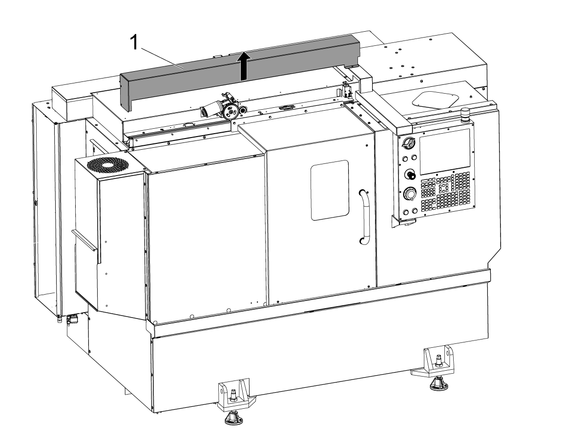
    자동 도어 커버[1]를 제거하십시오.

    2

    ST-20/25 및 DS-20Y/25Y:

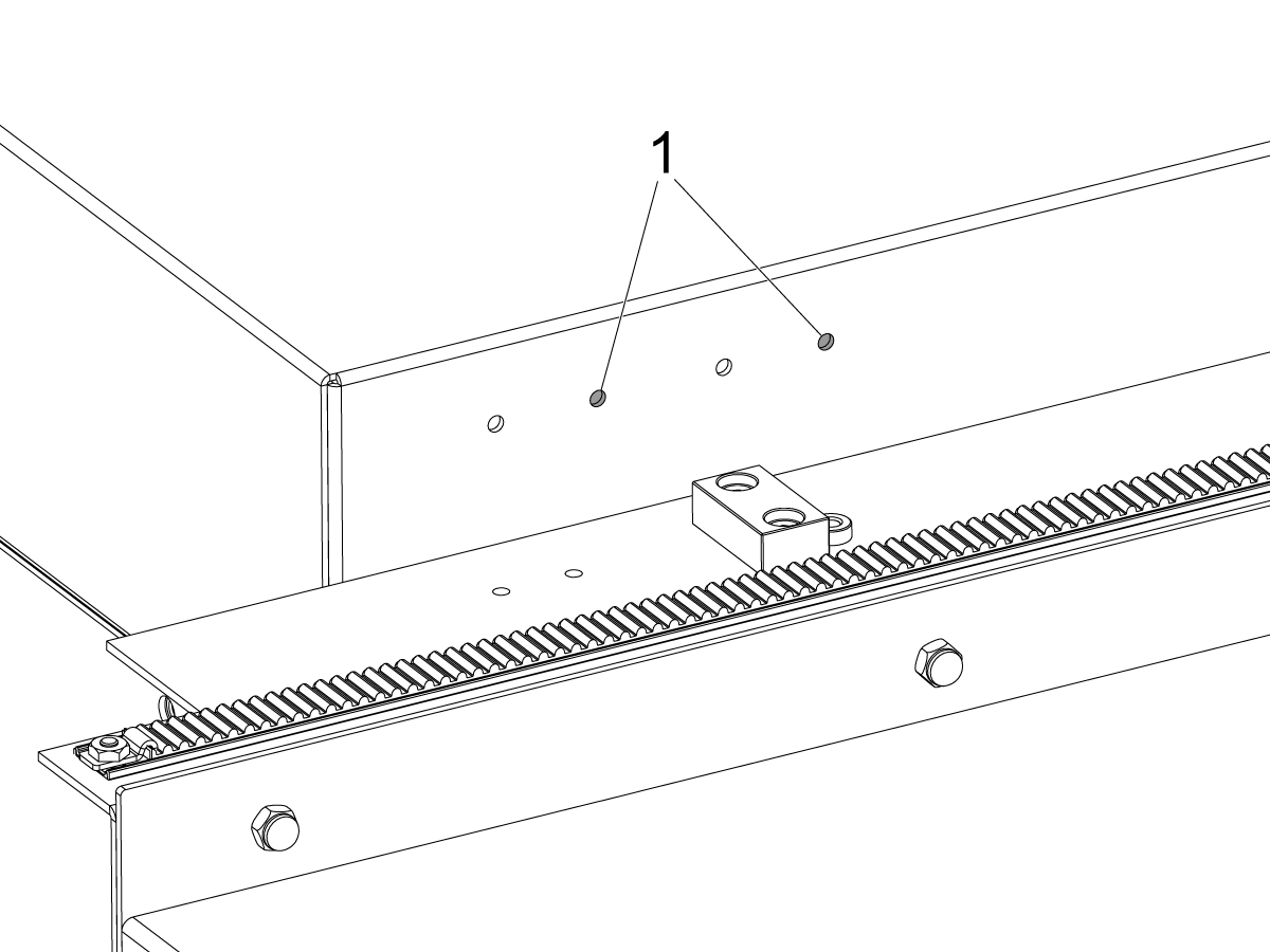
    루프 패널에 스위치 브래킷 구멍이 있는 기계용. ST-20/25용 [1]구멍의 오른쪽 쌍에 스위치 브래킷을 설치합니다.

    3

    루프 패널에 스위치 브래킷 구멍이 없는 기계용.

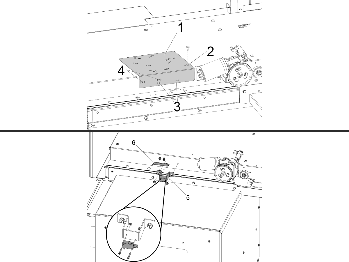
    제공된 드릴 가이드[1]를 사용하여 DOOR FULLY OPEN 상태 스위치용 장착 구멍을 드릴합니다.

    하나의 슬롯[2]으로 표시된 드릴 가이드 상단의 가장 오른쪽 구멍을 자동 도어 모터 왼쪽의 자동 도어 커버 장착 구멍에 맞추고 BHCS로 고정하십시오.

    ST-10/15:

    • 슬롯 하나[3]가 표시된 드릴 가이드 구멍에  Ø 3/16"(4.7mm) 장착 구멍 두 개를 드릴합니다.

    ST-20/25 및 DS-20Y/25Y:

    • 양쪽[4]에 두 개의 슬롯이 표시된 드릴 가이드 구멍에  Ø 3/16"(4.7mm) 장착 구멍 두 개를 드릴합니다.

    제공된 자동 태핑 나사를 사용하여 DOOR FULLY OPEN 스위치 어셈블리[5]와 DOOR FULLY OPEN 트립 플래그[6]를 설치합니다.

    4

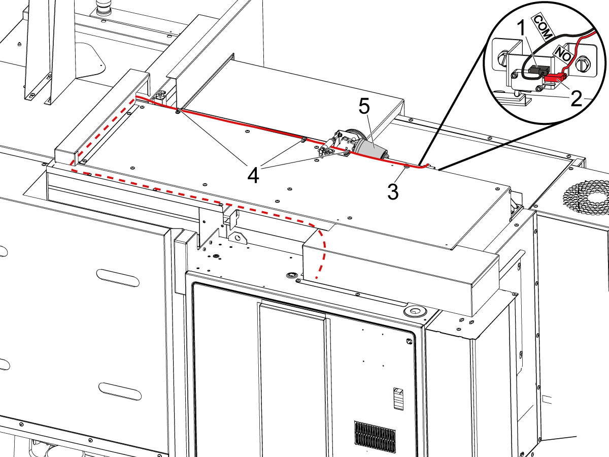
    아래에 명시된 대로 DOOR FULLY OPEN 스위치를 연결하십시오.

    • BLK <COM>을 상단 단자 [1]에.
    • RED <NO>를 중간 단자 [2]에.

    그림과 같이 케이블을 제어 캐비닛에 배선하십시오.

    참고: 움직이는 오토 도어 모터[5]에 케이블이 닿지 않도록 제공된 자동 클립[3]과 케이블 클램프[4]를 설치하십시오.

    5

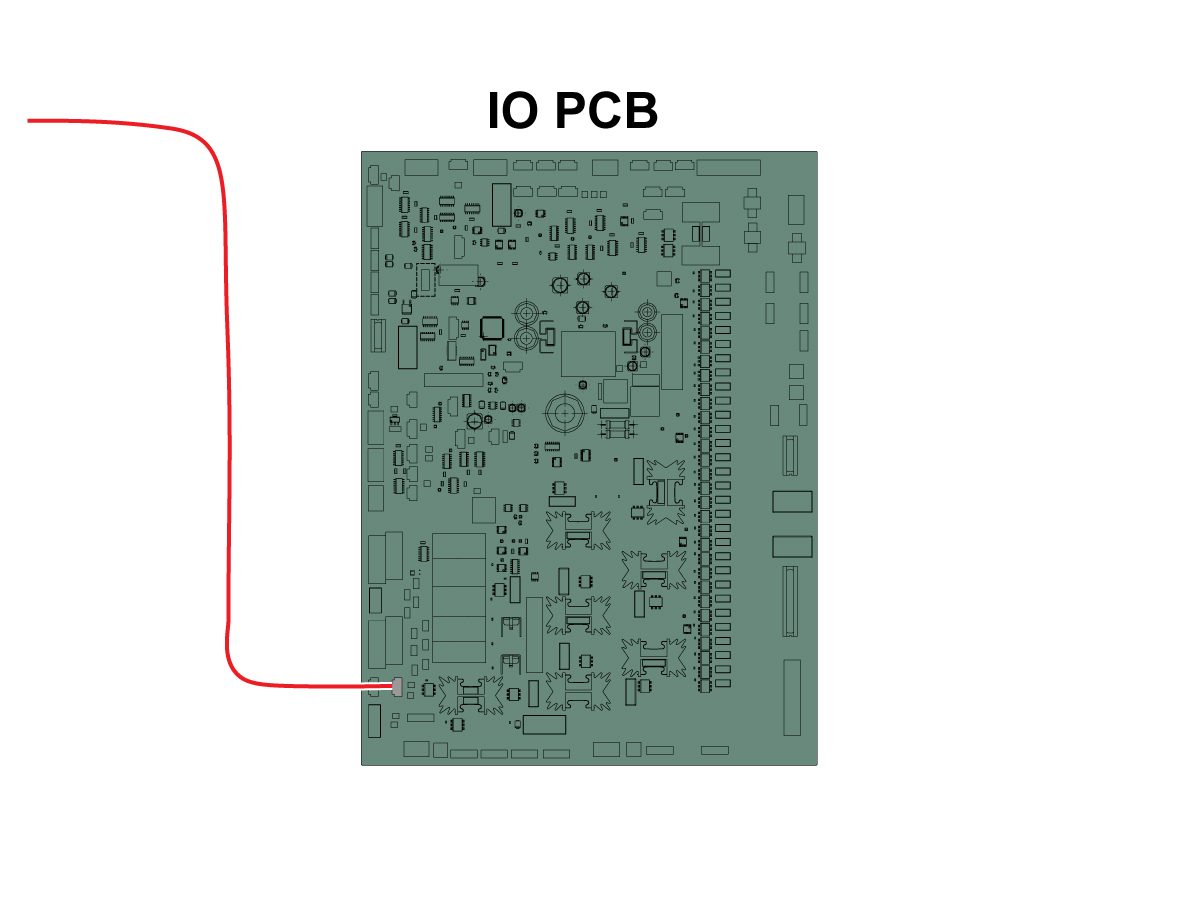
    케이블의 다른 쪽 끝을 SIO PCB P27 RRI Door Open 입력에 연결하십시오. 

    참고: 기계가 꺼져 있는지 확인하십시오.

    자동문 덮개를 설치하십시오.

    6

    • APL 스프링 푸셔는 25mm 또는 1인치 툴 홀더에 맞는 자루로 제작
    • 이 도구는 터렛에서 공구 홀더에 있어야 함
    • 기계가 ST-10/15 인 경우, 그리퍼를 위한 충분한 공간을 확보하기 위해 2개의 빈 공구 홀더 필요
    • 다음 단계를 모든 프로그램의 시작 부분에 프로그래밍하여 부품이 척에 올바르게 장착되도록 프로그래밍하십시오.
      • 부품 앞에서 스프링 푸셔 찾기
      • Z축을 움직여 스프링을 약 0.50인치 또는 12.7mm로 압축
      • 1초의 일시 정지로 척 열기
      • 1초의 일시 정지로 척을 닫기
      • 터렛을 가능한 가장 안전한 위치로 복귀시키기

    참고: 스프링 푸셔의 부품 번호는 다음과 같습니다. 

    • 30-12642 SPRING PUSHER.  25mm 또는 1.0인치 홀더는 별도로 판매됩니다.

    Cobot Installation

    1

    코봇 과제어 박스가 일치하는 일련 번호와 일치하는 세트에서 왔는지 확인합니다.

    Haas 일련 번호[1]가 있는 흰색 데칼이 있습니다. 두 상자에서 모두 동일한지 확인하십시오.

    식별 번호[2]가 있는 노란색 원 데칼이 있습니다. 두 상자에서 모두 동일한지 확인하십시오.

    2

    기계 스커트에서 받침대 측면까지의 거리를 측정합니다.

     참고: 다음 치수는 권장 거리입니다. 위치는 사용자 응용 장치에 따라 다를 수 있습니다. 

    다음 단계의 치수를 전면 및 측면 로딩 코봇의 기준으로 사용하십시오. 

    Haas 코봇 10은 Haas 코봇 받침대와 페어링하는 것이 좋습니다. 이 받침대는 Haas에서 정의한 공작물 크기 및 중량 제한에 따라 사용할 때 충분히 안정되도록 구성되어 있습니다. 

    3

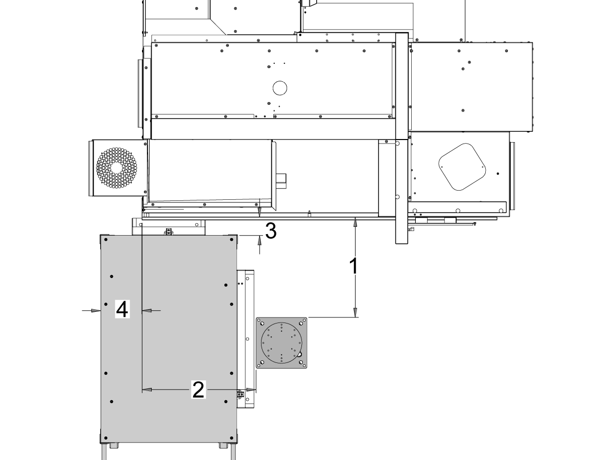
    ST-10 및 ST-15 기계:

    기계를 기준으로 다음 위치에 받침대와 공작물 테이블을 배치합니다.

    치수 야드파운드법(인치) 미터법(cm)
    기계 전면에서 받침대 전면까지 [1] 24.5인치 62.2cm
    기계 왼쪽에서 받침대 왼쪽 측면까지 [2] 26.25인치 66.7cm
    기계 전면에서 공작물 테이블 [4] 5.5인치 14cm
    기계 왼쪽에서 공작물 테이블[4]의 왼쪽 9.75인치 24.7cm

    4

    Updated

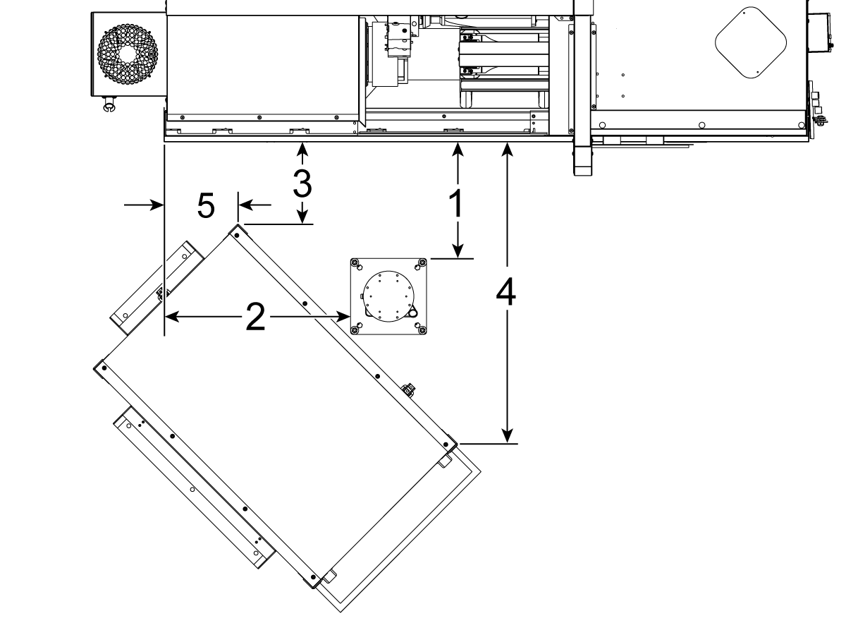
    ST-20 및 ST-25 기계 & DS-20Y/25Y:

    기계를 기준으로 다음 위치에 받침대와 공작물 테이블을 배치합니다.

    치수 야드파운드법(인치) 미터법(cm)
    기계 전면에서 받침대 전면까지 [1] 19.5인치 49.5cm
    기계 왼쪽에서 받침대 왼쪽 측면까지 [2] 28.5인치 72.4cm
    기계 전면에서 공작물 테이블 [3]의 전면 왼쪽 모서리까지 14.5인치 36.8cm
    기계 전면에서 공작물 테이블 [4]의 전면 오른쪽 모서리까지 71인치 180cm
    기계 왼쪽에서 공작물 테이블 [5]의 전면 왼쪽 모서리까지 10.75인치 27.3cm

    5

    ST-30/35 및 DS-30Y 기계:

    기계를 기준으로 다음 위치에 받침대, 공작물 테이블, 코봇 제어 박스[5]를 배치합니다.

    치수 야드파운드법(인치) 미터법(cm)
    기계 전면에서 받침대 전면까지 [1] 8.5인치 21.6cm
    기계 왼쪽에서 받침대 왼쪽 측면까지 [2] 42.0인치 106.7cm
    기계 왼쪽에서 공작물 테이블의 왼쪽까지[3] 23.5인치 59.7cm
    기계 전면에서 공작물 테이블 [4] 24.0인치 61.0cm

    6

    받침대를 지면에 고정합니다. 버블 레벨을 사용하여 받침대의 수평을 맞춥니다. 

     참고: 조정 가능한 받침대의 경우 고정 나사[1]를 푼 다음 클레비스 핀[2]을 조정하여 원하는 높이를 설정합니다. 로봇을 설치하기 전에 세트 스크루[1]를 다시 조입니다. 베이스에 (x4) 육각 볼트를 사용하여 X 및 Y 평면에서 레벨을 설정하는 동안 받침대 상단에 기포 수준기를 놓습니다.

    케이블이 충분히 느슨해지도록 코봇 제어 박스[3]를 받침대 바로 옆에 놓습니다. 

    7

    배송 상자에서 로봇을 제거합니다. 

     참고: 필요한 경우 받침대와 로봇 사이에 어댑터 플레이트를 설치합니다. 

    받침대 위에 코봇 을 설치합니다.

     참고: 코봇 케이블 커넥터[1]가 기계 전면과 직각을 이루는지 확인하십시오. 

    중요: 코봇 은 약 40lbs이며 해당 무게를 안전하게 들어 올릴 수 있는 장치로 들어 올려야 합니다.

    로봇을 설치한 후 로봇 리프팅 하드웨어를 제거하십시오.

    8

    코봇 패키징 내부에는 다음과 같은 예비 부품으로 채워진 작은 백[1]이 있습니다. 

    • 퓨즈
    • 나사 (x2)
    • 제어 박스 키

    여분의 M12 커넥터로 채워진 중간 크기의 백[2]이 있습니다. 이 케이블을 사용하여 End I/O 모듈의 입력 및 출력을 구성할 수 있습니다. 

    종이로 채워진 대형 백[3]과 코봇 소프트웨어로 다운로드한 USB 스틱이 있습니다.

    나중에 사용할 수 있도록 이러한 예비 부품을 안전한 곳에 보관하십시오. 

    Robot Electrical & Air - Installation

     DANGER: Working with the electrical services required for CNC machines is extremely hazardous and can result in serious injury or death.

    Before connecting line wires to the CNC:

    • Turn off all power to the machine at the source.
    • Perform a Lockout-Tagout (LOTO) procedure to ensure the power remains off during service.
    • Verify that power has been disconnected by using an AC voltage detector on all incoming lines.

    If you are uncertain about how to safely disconnect power or perform LOTO procedures:

    • Do not proceed.
    • Contact qualified personnel or obtain appropriate assistance before continuing.

    Failure to follow these precautions may result in electrical shock, equipment damage, or fatal injury.

     Danger: Before beginning any work inside the control cabinet, verify that the High Voltage indicator light on the 320V Power Supply / Vector Drive has been off for a minimum of five (5) minutes. This waiting period ensures that residual voltage has dissipated and reduces the risk of electric shock.

    Certain service procedures involve high-risk electrical components and may pose serious injury or fatality hazards. Technicians must not attempt any procedure unless they have a complete understanding of the steps involved and the associated risks.

    If there is any uncertainty regarding a procedure, contact your Haas Factory Outlet (HFO) to arrange for a qualified service technician.

    1

    Connect Interface Box to Haas Machine:

    The robot safety devices interface box 32-9018 has magnetic mounts to attach to the machine sheet metal. Mount the interface box [1] as shown in the picture.

    Route the interface electrical cables [2] along the enclosure with the magnetic mounts and zipties. Route the cable through the bottom of the electrical cabinet.

    NOTE: For information on upgrading the interface box to the Robot Safety Devices Interface Box, refer to the Robot Safety Devices Interface Box - Installation - AD0703. 

    2

    Connect Interface Box to Haas Control Cabinet:

    Connect cable 33-8562C E-STOP terminal block to TB-1B [1] and connect the Setup mode terminal block to TB-3B [1] on the SIO PCB.  

    Plug the user relay into K9 and K10 [2].

    Verify the jumper is installed on the SIO PCB at JP1.

    Connect the pigtail cable labeled P1 SIO to the SIO PCB at P1 [3]

    NOTE: If the machine has a Regen Vector Drive, unplug cable 33-0634 FILTER OV TO IOPCB P1 from P1 SIO and plug it into the connector FILTER OV FAULT on cable 33-8562C. If the machine does not have a Regen Vector Drive, do not plug anything into the connector FILTER OV FAULT.

    Connect the RJ-45 cable [4] to Ethernet to USB adapter [5] (33-0636).  Connect the USB connector end to the Maincon PCB J8 top port. Add a ferrite filter [6] to the USB adapter.

    Mount the 24VDC Power Supply [7] to the left side of the control cabinet and plug into connector labeled 24V PS on cable 33-8562C. Connect cable 33-1281 [8] to the 24VDC Power Supply [7] and plug into P3 on the PSUP PCB. 

    3

    For MM/SMM CM/CL machines Without XMR

    If P3 is occupied by a jumper connected from P3 [10] to P7 [9] on the PSUP PCB, a splitter cable is needed to allow the 24VDC power supply [7] to be connected to the 120VAC connectors on the PSUP. Connect the male connector of the splitter cable to P3 [10] and then connect the jumper from that cable to P7 [9] and also cable 33-1281 [8].

    Note: Make sure that the jumper cable is connected where the red lines up with the red from the splitter cable.

    4

    Inside the Cobot control box, install part of the robot signals cable (33-1272 or 33-1351).  To do so, remove the safety connector [1] from the Cobot control box in order to install the different colored wires into their respective location

    33-1272 / 33-1351 cables [2] going to safety connector:

    • Gray wire to top 24V
    • Red wire to bottom 24V
    • Green wire to EI0
    • Brown wire to EI1
    • Jumper [3] from SA0 to SA1
    • Jumper  [4] from SB0 to SB1

     NOTE: The rest of the wires from this cable are not used. Put some electrical tape on each wire lead and Ziptie the leftover unused wires. 

    5

    Important: After installing all the cables from the robot signal cable, make sure that the fuse [1] remains installed at all times to protect the Cobot control box.

    6

    Connect Cobot to the Interface Box:

    Connect the RJ45 ethernet cable [1] from the Cobot Control Box to the interface box. Add a ferrite filter [2] to the RJ-45 cable.

    Connect the robot signals cable [3] from the Cobot Control Box to the interface box. 

    Connect the 120 VAC Cobot Power Cable [4] to the external power source. 

    Connect the robot power cable [5] from the control box to the Cobot.

    Connect the teach pendant cable [6] from the control box to the teach pendant. 

    NOTE: For more information regarding interlock fence, area scanner or light curtain installation, refer to the Robot Safety Device section below.

    7

    Make sure the Remote Jog Handle is installed onto the machine.

    NOTE: For more information on the RJH-XL installation, refer to Remote Job Handle - Touch Large (RJH-XL) - Installation - AD0533. 

    8

    Steps 7 thru 10 are wiring and hose routing instructions for the pneumatic grippers. Refer to the grippers installation section lower on this page for the mechanical installation.

    Install the dual air solenoid assembly on to the side of the pedestal while giving the airlines enough slack. Make sure it's in a position where it will not be in the way. Route the airline [1] under the machine back towards the CALM cabinet as shown.

    9

    Inside the CALM cabinet, remove a plug from one of the CALM manifold ports and install the check valve [1] (58-1863) onto the port's fitting. Route the input airline [2] from the dual air solenoid assembly (from previous step) into the CALM cabinet and connect the airline to the check valve.

    Turn the machine air supply ON.

    10

    Make sure to power OFF the control box [1].

    Connect the solenoid cable from the dual air solenoid assembly [2] into the Digital Output on the Cobot control box [1]. Remove the connector from Cobot control box.

    11

    Connect the gripper solenoid power cable (33-1276 / 33-1341) to the Digital Output terminal inside the control box. Install the different colored wires into their respective location:

    • Black/white cable into 0V
    • Black cable into DO0
    • Orange/white cable into 0V
    • Orange cable into DO1
    • Red/white cable into 0V
    • Red cable into DO2
    • Brown/white cable into 0V
    • Brown cable into DO3

    Power ON the control box.

    Robot Safety Device

    중요: 안전 장치의 작동을 올바르게 구성하고 테스트할 때까지 로봇을 작동하지 마십시오.

    광 커튼

    코봇 패키지는 광 커튼 송신기 및 리시버와 함께 기본 안전 장치로 제공됩니다. 광 커튼은 아래 절차에 따라 설치하십시오. 

    광 커튼 설치

    참고: 영역 스캐너 또는 HC10 기계 준비 키트를 주문한 경우 1M 광 커튼 수신기 및 송신기도 있습니다. 모든 코봇에 함께 제공됩니다.

    로봇 펜스:

    기계에 펜스 옵션이 장착된 경우 기계에 로봇 펜스 및 도어 인터록 어셈블리를 설치해야 합니다. 아래 절차에 따라 설치하십시오.

    로봇 펜스 설치

    펜스가 설치되면 기계와 로봇 펜스 사이에 펜스 패널을 설치합니다.

    영역 스캐너

    기계에 영역 스캐너 옵션이 장착된 경우, 영역 스캐너를 공간에 설치하고 구성해야 합니다. 아래 절차에 따라 설치하십시오. 

    영역 스캐너 설치

    First Power-UP

    1

    Power ON the Haas machine. 

    Power ON the Cobot by flipping the power switch [1].

    Power ON the Cobot teach pendant by pressing the circle [2]. 

    Make sure that E-STOP [3] on the Cobot teach pendant is released. 

    In order to change the language, click on the language drop down menu. Choose EN for English. To confirm this setting change, the Cobot teach pendant will have a popup asking to insert the username & password. 

    Enter "admin" for both the username and password. 

    2

    Note: The Cobot teach pendant will have a popup asking to insert the username & password. To sign into the teach pendant use these credentials:

    • Username = admin
    • Password = admin

    Go into Run mode. Press Enable. 

    Go into Jog mode [1].

    Move each joint to it's zero location with the Move Zero buttons [2]. 

    3

    Once the robot is in it's zero location, verify that the hash lines [1] align on either side of each joint on the Cobot. 

     IMPORTANT: If any joint hash lines [1] do not align, jog the specific joint accordingly until all the hash lines [1] do align. This position will be set in the next step as the new Cobot zero position.  

    Connect an ethernet cable [2] from the Cobot control box into a computer.

    On the computer, change the adapter setting to enable the ethernet port. 

    Note: See next steps for help on changing adapter settings.

    4

    To change the adapter settings, open the settings page [1] on the computer, then click on Network & Internet [2] which will bring up the network status page.

    Click on Change adapter options [3] then right click on Ethernet [4] and open up the properties window [5]. From there select the Internet Protocol Version 4 (TCP/IPv4) [6] option and click Ok. 


    5

    The ethernet settings will now be correct. Open a web browser window and type in the IP address of the Cobot[1]. 

    Note: This is the same process as connecting a laptop to an HRP-1/2/3. For more information on connecting to the Cobot via ethernet, refer to the video on the HRP-Troubleshooting page that is in the Connect & Jog Haas Robot section. 

    6

    Download HRTool through HBC. On the Service section of HBC, navigate to Utilities > Documents and Software > 01 Control Software > 01 Next Generation Control > 10 Cobot Software > HRTool.zip.

    Unzip the folder and navigate to HRToolsMaind.exe.

    Insert the Cobot IP address found under the Systems tab.  Click Set. 

    Go to the Config tab on HRTool.

    Click "get" to see the actual vs. theoretical encoder values. 

    Click "set" to set the theoretical to the actual encoder values. This step sets the Cobot's current position as it's new home position. 

    7

    Make sure that each joint's actual and theoretical encoder values match. 

    NOTE: If the valuyes do not match, press "Set" again. 

    8

    On the teach pendant, navigate to System [1] and then Update System. 

    Confirm the Cobot firmware [2] is either:

    • HR5.51H.16.beta.20231213.zip
    • HR6.4.9.tmp.20240919.zip

    NOTE: Firmware version HR6.4.9.tmp.20240919.zip is compatible with all size cobots.

    Refer to the Haas Cobot - Maintenance chapter for the firmware update procedure. 

    9

    Turn on the Haas CNC.

    Zero Return all Axes.

    Insert Service USB key.  Go into Service mode.

    Go to Parameters> Factory tab.  Change the following:

    • 1278 [1278:] Robot Ready E-Stop Enabled to TRUE
    • 2191 [694:] LIGHT CUTAIN TYPE to LC_TYPE_1
    • 2194 [:] Enable Front Door Fully Open Switch to TRUE

    Note: Machines with Software Version 100.20.000.1010 or higher will need to change the following parameter:

    • 2192 [:] Light Curtain Trigger Threshold to 0

    Press [SETTING].

    Set the Settings:

    • 372 Parts Loader Type to 3: Robot.
    • 376 Light Curtain Enabled to On


    10

    On the Haas pendant, press [CURRENT COMMANDS].

    Go to Devices>Robot>Jogging tab. Change the following:

    • Maximum Jogging Speed to 7.9 inch/sec

     Note: The jogging increments on the RJH are a percentage of this max speed value. In order to decrease the distance the robot travels of each jog wheel tick, you need to change your Maximum Jogging Speed to a lower value.

    Go to the Setup tab. Change the following:

    • Max Robot Speed to 118 in/sec (2000 mm/sec). 
    • Enter the Net Mass of the gripper. Refer to the layout drawings on our website (Single Gripper layout drawing OR Dual Gripper layout drawing) to get the correct value for this setting
    WARNING: Setting this value incorrectly can cause the Robot Arm to not move correctly. 
     
    • Number of Grippers to the number of grippers.
    • Raw Gripper Clamp Output to 1.
    • Raw Gripper Unclamp Output to 2.
    • Raw Gripper Clamp Delay to the clamp/unclamp duration in sec.
    • Raw Gripper Clamp Type to OD/ID.
    • Finish Gripper Clamp Output to 3.
    • Finish Gripper Unclamp Output to 4.
    • Finish Gripper Clamp Delay to the clamp/unclamp duration in sec.
    • Raw Gripper Clamp Type to OD/ID.

    Security Risk Level

    1

    IMPORTANT: Make sure to perform an appropriate risk-assessment and met all appropriate safety requirements. 

    2

    Based off the risk assessment, set the appropriate security risk level on the Cobot teach pendant. Navigate to Config > General Restrictions and tap of the desired security risk level [1] from 0 - 5.

    Use the  "admin" code in the safety verification to change the security level.

    NOTE: When the security risk level is lower, the robot will have a lower maximum speed, force, etc. When the security risk level is higher, the robot will have a higher maximum speed, force, etc. 

    This security risk level will calculate the maximum allowable force, speed, power, momentum, elbow speed and elbow force [2] that the Cobot will withstand before Alarm 9150.10017 Collison Stop Error is triggered. 

    IMPORTANT: The robot's programmed speed cannot be greater than the allowable speed from the security risk level. 

    NOTE: For more information regarding alarms, refer to the Haas Cobot - Troubleshooting Guide. 

    Activation

    1

    Download and load the configuration files by logging into the HAAS SERVICE PORTAL.

    Download the safety automation option front/side configuration files.

    Load the option configuration patch file to the control. Refer to the NEXT GENERATION CONTROL - CONFIGURATION FILE - DOWNLOAD/LOAD procedure.

    2

    Go to Parameters > Features > Robot to verify that the robot feature has appeared on the bottom.

    3

    Press [CURRENT COMMANDS].

    Go to Devices>Robot>Setup tab [1].

    Press [E-Stop].

    Press [F1] to connect the robot[2].

    The first time connecting a robot to a machine, the robot feature will need to be unlocked. This popup shows the machine's current software version, robot mac address and a generated code. Enter this information into HBC in order to receive the unlock code.

    4

    On HBC, go to the Service tab [1].

    On the left hand side of the screen, click on Activations [2], and then select Cobot Installation [3] to begin the process to the get the Cobot unlock code.

    The first step is to enter the Machine Serial Number [4] and the Cobot Serial Number [5] in the fields on HBC.

    Once you have entered the correct information, press Next [6] in the bottom right corner and continue through the steps until you receive the unlock code.

    Note: Make sure you are on the Cobot Installation tab [3] and not the Robot Installation tab. The Robot Installation is only used for the Haas Robot Packages. Using the Robot Installation for the Haas Cobots will result in an invalid unlock code.

    5

    Enter the Cobot's Haas Serial Number[1] and the unlock code to connect the robot to the machine. 

     Note: This step can only be completed by a HFO Service Technician.

     Note: The machine needs to be activated before the Cobot is activated. Follow the Machine Activation / Time Extension - NGC procedure.

    When the robot has connected with the machine, a yellow message saying Robot Activation Successful should appear at the bottom of the Haas screen.

    6

    Release the [E-STOP] and press RESET to clear the alarms. 

    Press the [HANDLE JOG] button. 

    Press the [CURRENT COMMANDS]  and go to Devices > Robot > Jogging tab.

     Note: The robot in setup mode can only be handle jogged while the F2 button the RJH is pressed. See Setup/Run mode section below.

    On the Remote Handle Jog Touch press the Joint button to go into the Joints Coordinates.

    Move the robot to an accessible location to install the grippers.

    Jog J6 to 0.0000 position. The location hole should be centered on top.

    Note: Press [E-STOP] before working on the robot.

    Gripper Installation

    1

    Turn off the machine air by turning the valve in the Air/Lube cabinet and pull the pressure relief valve to release the air in the system.

    2

    For the Dual Action Gripper:

    There are two versions of the dual-action grippers for this section, both of which have the same installation process.

    Jog the robot so that the location hole [1] is centered on top.

    Install the adapter plate [2] onto the end of the robot arm.

    Install the dual gripper assembly [3] onto the adapter plate [2].

    NOTE: Make sure to install Gripper 1 (which has the orange and purple zip ties) onto the Gripper 1 adapter plate section. 

    3

    For the Angled Single Action Gripper:

    Jog the robot so that the location hole [1] should be centered on top.

    Install the angle adapter plate [2] to the end of the robot arm.

    Install the single gripper assembly [3] onto the angle adapter plate [2]. 

    4

    To install the bar gripper fingers, remove the slug gripper plates from the gripper bodies.

    Install the Bar Gripper Bolt Plates [3] with (x8) SHCS M6 screws [4]. Torque to 10 ft-lbs.

    Install the Bar Gripper Fingers [2] with (x8) SHCS 1/4-20 [1]. Torque to 13 ft-lbs.

    5

    Configure the dual air solenoid assembly used for pneumatic grippers depending on single [1] or dual [2] gripper configuration. 

    For single grippers [1], connect the incoming air to the to the fitting [2] and keep the plug in the other end of the fitting [3] as shown in the image.

    For dual grippers [4], remove the plug in the fitting [3] and attach a small air hose to the second solenoid [5]. Then connect the incoming air hose to the fitting [2] so that both solenoids are receiving air.

    6

    For the Single Gripper:

    Route the (x2) air lines from the gripper to the same color coded fitting on the dual air solenoid assembly. 

    Secure the air lines by wrapping them in cable conduit. Use the velcro straps to attach the cable conduit to the Cobot. Make sure there is enough slack so that cables aren't strained when Cobot is fully extended.

    Insert the input air hose to the used solenoid's fitting [1]. 

    Make sure the plug is installed onto the unused solenoid's fitting [2]. 

    7

    For the Dual Gripper:

    Route the (x2) air lines from gripper #1 to the same color coded fitting on the dual air solenoid assembly. 

    Route the (x2) air lines from gripper #2 to the same color coded fitting on the dual air solenoid assembly. 

    Secure the air lines by wrapping them in cable conduit. Use the velcro straps to attach the cable conduit to the Cobot. Make sure there is enough slack so that cables aren't strained when Cobot is fully extended.

    Insert the short airline [1] connecting the first solenoid with the second. 

    Insert the input air hose to the fitting [2]. 

    Parts Table Assembly

    If the parts table option was ordered, follow the procedure below for assembly instructions:

    Haas Robot - Parts Table Assembly

    NOTE: If HC10 MACHINE READY KIT was purchased, there is no need to install the wheels if mounting the parts table directly into the wooden pallet. 

    Verification

    Test the E-stop:

    • Press each E-STOP button located on the Haas Pendant, RJH-XL, and Cobot Teach Pendant. Make sure the machine generates 107 EMERGENCY STOP alarm.  If the E-STOP button does not generate a 107 EMERGENCY STOP alarm verify the wiring. Load the latest configuration files to enable the RJH-XL.

    Test the Robot Safety Device:

    Make sure that there is an E-STOP or light curtain triggered icon on the Haas pendant when the robot safety device is triggered. 

    • Fence - Insert the key into the interlock, verify that the two red LED lights in the front of the interlock are OFF. Remove the key from the interlock, verify that the two red LED lights are ON. 
    • Area Scanner - Step inside the protective field, verify that the red LED lights up on the area scanner. Step outside the protective field, verify that the green LED lights up.
    • Light Curtain - Interfere the light curtain beams, verify that the light curtain triggered icon appears on the Haas pendant. Press [RESET]. Step outside of the light curtain beams, verify no icon appears on the Haas pendant. 

    NOTE: If the light curtain triggered icon does not show, verify wiring, alignment and factory setting: 2191 [694:] LIGHT CURTAIN TYPE is set to LC_TYPE_1.

    Test the Operation of the Grippers:

    • Verify that both grippers clamp and unclamp correctly.
    • Press the [CURRENT COMMANDS]  and go to Devices > Robot > Jogging tab.
    • Press [F2] to clamp/unclamp the Finish Gripper.
    • Press [F3] to clamp/unclamp the Raw Gripper.

    Test the Remote Jog Handle:

    • Undock the Remote Jog Handle
    • Press the [HANDLE JOG] button. 
    • Press the [CURRENT COMMANDS]  and go to Devices > Robot > Jogging tab.
    • On the Remote Handle Jog press the Joint button to go into the Joints Coordinates.
    • Move the robot to a safe location.

    IMPORTANT: If a yellow warning message appears saying "Please activate Light Curtain or Cell Safe" while trying to job the robot, verify the safety parameter was applied by re-uploading the configuration files from HBC. 

    Verify Safe / Run Mode Operation

    All Haas CNC machines are equipped with a key switch on the side of the control pendant to lock and unlock setup mode. The robot will have the following behaviors depending on what mode is selected. 

    • When the Haas control is in Run mode, mode 1, triggering the robot safety device stops all motion. This motion can not be started until the robot safety device is no longer triggered.
    • When the Haas control is in Set up mode, mode 2, speed limited motion such as jogging an axis of the robot can be performed in order to program a robot's path of motion, pick up position, set a robot's tool center point, (an offset), load and pick up parts from the spindle or part holder in the machine, etc. The programmed path will also be able to be run slowly to prove out the programmed path of the robot. The robot in setup mode can only be handle jogged while the F2 button the RJH is pressed.

    Haas Robot - Quick Start Guide

    로봇을 설치 한 후 아래 절차에 따라 작업을 설정하십시오.

    Haas Robot - 빠른 시작 안내서

    Disable the Robot

    독립 실행형 모드에서 기계를 실행하기 위해 APL을 비활성화하려면 다음과 같이 합니다. [SETTING]을 누릅니다. 설정을 다음과 같이 변경합니다.

    • 372 Parts Loader Type을 0: 없음
    • 376 Light Curtain Enabled을 Off


    5.3 DM/DT/MM/DC-1/UMC-350 설치

    Recently Updated

    Haas Cobot 10(HC10) - DM/DT/MM/DC-1/UMC-350 - 설치


    AD0716

    개정판 D - 2025년 11월

    Introduction

    Updated

    이 절차는 Haas 10KG 코봇(HC10)을 설치하는 방법을 보여줍니다.

    참고: CNC 기계와 로봇으로 구성된 Haas 설계 작업 셀은 CE 요건을 준수하는 것으로 평가되었습니다. Haas 셀 디자인에 대해 변경 또는 변형하는 경우 해당 표준을 준수하는지 평가해야 하며 이는 사용자/통합 회사의 책임입니다.

    기계 요구 사항:

    • 100.24.000.1001 버전 이상
    • HR5.51H.16.beta.20231213.zip 버전 또는 HR6.4.9.tmp20240919.zip 버전.
    • DT/DM/MM/SMM/DC-1/UMC-350 제작일: (각 절차의 기계 요구 사항 참조) 
      • Haas 자동문 
      • Haas 자동 창
         참고: MM/SMM, DM-3, DT-3 및 DC-1은 측면 로딩 옵션(93-1001053)에서만 사용할 수 있습니다.
      • 참고: 변압기가 없는 MM/SMM 기계에는 현장 설치된 코봇을 위해 주문해야 하는 스플리터 케이블이 필요합니다. 스플리터 케이블은 93-5067로 주문할 수 있습니다.
    • 34-349xB I/O 보드 이상
    • 93-1000610 원격 조그 핸들 TOUCH LCD(RJH-XL) 원격 조그 핸들 - XL  

    공구 요구 사항

    • 미니 일자 드라이버

    Fixing / Anchoring Requirements

    • The Haas 10KG Cobot (HC10) is configured and sold by Haas with a pedestal/table that is sufficiently stable when used according to Haas defined part size and weight limits. 
    IMPORTANT:  For more information directly on the Hans Cobot, refer to the Hans Robot Operation Manual for Elfin Software.

    There are 3 scenarios in which the cobot option can be installed on a Haas machine:

    1. Cobot option was ordered at the same time as the machine. Both the cobot and the machine are being installed together.
    2. Cobot option is ordered so that it can be installed on a previously installed machine.
    3. Cobot option was previously installed on a machine, but will now be moved to a different Haas machine.

    In scenarios 2 and 3, additional parts will need to be ordered under the Serial Number of the Haas machine. See the tables below for what parts are needed in the different scenarios.

    Scenario 1 - Cobot and Machine are ordered and installed together

    Component Part Number Description
    NO ADDITIONAL PARTS NEED TO BE ORDERED WHEN COBOT AND MACHINE ARE ORDERED TOGETHER

    Scenario 2 - Cobot being field installed on existing Haas Machine

    Component Part Number Description
    CHECK TO SEE IF HAAS MACHINE ALREADY HAS THESE FEATURES & PARAMETERS BEFORE ORDERING
    Robot Feature Unlock Parameter 93-1001031 Kit activates the robot feature on the Haas machine. To check if you need this kit, go to the Features tab on the Haas Control and check if the Robot option is highlighted. This kit does not include any physical parts.
    Load Type Safety Parameters 93-1000997 Front Automation Safety Parameters - Kit is needed when the cobot will be loading parts through the front door of the Haas machine. This kit does not include any physical parts and the autodoor option would need to be purchased and installed separately.
    OR  
    93-1000996 Side Automation Safetly Parameters - Kit is needed when the cobot will be loading parts through the side window of the Haas machine. This kit does not include any physical parts and the autowindow option would need to be purchased and installed separately.

    Scenario 3 - Cobot is being transferred from one machine to a different Haas Machine

    Component Part Number Description
    Cobot Integration Kit See Integration Kit Compatibility Chart Kit is needed to install parts on the Haas machine to interface with the cobot. This includes the interface box, door switches, etc... as well as the Robot Unlock Feature parameter. This kit only needs to be purchased when transferring a cobot to a new Haas machine since these parts are normally included when a cobot is ordered. 
    Load Type Safety Parameters 93-1000997 Front Automation Safety Parameters - Kit is needed when the cobot will be loading parts through the front door of the Haas machine. This kit does not include any physical parts and the autodoor option would need to be purchased and installed separately.
    OR  
    93-1000996 Side Automation Safetly Parameters - Kit is needed when the cobot will be loading parts through the side window of the Haas machine. This kit does not include any physical parts and the autowindow option would need to be purchased and installed separately.
    Safety Device 08-1899 Multi-Sided Light Curtain Kit - Kit is needed if the safety device is NOT going to be transferred from the first machine and the second Haas machine needs it's own safety device. This kit makes a 4-sided protective barrier.
    OR  
    08-1948 5-Sided Light Curtain Kit - Kit is needed when the safety device is NOT going to be transferred from the first machine machine and the second Haas machine needs it's own safety device. This kit makes a 5-sided protective barrier.
    OR  
    08-1987 Laser Area Scanner Kit - Kit is needed when the safety device is NOT going to be transferred from the first machine machine and the second Haas machine needs it's own safety device. This area scanner has a sensing distance of 4meters.

    Machine Setup

    1

    전면 로딩 로봇:

    근접 센서[2]용 드릴 가이드[1]를 엔클로저 상단에 볼트로 고정합니다.

    엔클로저 측면을 통해 2x 10-32 구멍을 뚫고 두드립니다.

    • 드릴 크기: #21 또는 5/32"
    • 탭 10-32 NF

    드릴 가이드 [1]를 제거합니다. 

    도어 오픈 근접 스위치 [2]를 엔클로저 측면의 이 구멍에 설치합니다.

    근접 센서에 전원을 공급하여 도어에서 원하는 트립 플래그[3] 위치를 찾으십시오. 트립 플래그[3]가 근접 센서를 트리거하기에 적절한 위치에 있으면 구멍 위치를 표시합니다. 

    셀프 태핑 나사로 도어 측면에 트립 플래그 [3]를 설치합니다. 

    그림과 같이 도어 완전 개방 케이블을 제어 캐비닛에 배선합니다.

    근접 스위치 케이블을 SIO PCB P27 

    에 연결합니다.

    2

    측면 로딩 로봇:

    자동창의 에어 실린더[4]를 노출시키기 위해 커버[1]와 하드웨어[2]를 제거합니다. 그림과 같이 브래킷[3]과 에어 실린더가 부착되도록 에어 실린더[4]를 들어 올립니다.

    회색 및 노란색 에어 라인 튜브는 자동 창 공기 실린더에 연결해야 하며 공기 실린더의 포트에는 각 튜브가 연결되는 위치를 표시하기 위해 회색 및 노란색 지퍼 타이가 있습니다.

    자동 창의 에어 실린더 위에 커버 [2]를 설치합니다.

    3

    • APL 스프링 푸셔는 25mm 또는 1인치 툴 홀더에 맞는 자루로 제작
    • 이 공구는 공구 캐로슬에서 공구 홀더를 조여야 합니다.
    • 다음 단계를 모든  프로그램의 시작 부분에 프로그래밍하여 공작물이 바이스에 올바르게 장착되도록 프로그래밍하십시오.
      • 공작물 위에 있는 스프링 푸셔 찾기
      • Z축을 움직여 스프링을 약 0.50인치 또는 12.7mm로 압축
      • 1초의 일시 정지로 바이스 열기
      • 1초의 일시 정지로 바이스 닫기

    참고: 스프링 푸셔의 부품 번호는 다음과 같습니다. 

    • 30-12642 SPRING PUSHER.  25mm 또는 1.0인치 홀더는 별도로 판매됩니다.

    Cobot Installation

    1

    코봇 과제어 박스가 일치하는 일련 번호와 일치하는 세트에서 왔는지 확인합니다.

    Haas 일련 번호[1]가 있는 흰색 데칼이 있습니다. 두 상자에서 모두 동일한지 확인하십시오.

    식별 번호[2]가 있는 노란색 원 데칼이 있습니다. 두 상자에서 모두 동일한지 확인하십시오.

    2

    기계 스커트에서 받침대 측면까지의 거리를 측정합니다.

     참고: 다음 치수는 권장 거리입니다. 위치는 사용자 응용 장치에 따라 다를 수 있습니다. 전면 로딩 또는 측면 로딩 코봇에 대한 코봇 및 공작물 테이블의 위치 설정은 다음 단계를 참조하십시오.

    Haas 코봇 10은 Haas 코봇 받침대와 페어링하는 것이 좋습니다. 이 받침대는 Haas에서 정의한 공작물 크기 및 중량 제한에 따라 사용할 때 충분히 안정되도록 구성되어 있습니다. 

    3

    전면 적재:

    기계를 기준으로 다음 위치에 받침대와 공작물 테이블을 배치합니다.

    치수 야드파운드법(인치) 미터법(cm)
    기계 전면에서 받침대 전면까지 [1] 13인치 33cm
    기계 왼쪽에서 받침대 왼쪽 측면까지 [2] 24인치 61cm
    기계 전면에서 공작물 테이블 [3]의 전면 왼쪽 모서리까지 8인치 20.3cm
    기계 전면에서 공작물 테이블 [4]의 전면 오른쪽 모서리까지 42.25인치 107cm
    기계 왼쪽에서 공작물 테이블 [5]의 전면 왼쪽 모서리까지 6.25인치 15.9cm

    4

    측면 적재:

    기계를 기준으로 다음 위치에 받침대와 공작물 테이블을 배치합니다.

    치수 야드파운드법(인치) 미터법(cm)
    기계 전면에서 받침대 [1] 왼쪽 측면까지 21인치 53.4cm
    기계 오른쪽에서 받침대[2] 전면까지 13인치 33cm
    기계 전면에서 공작물 테이블 [3]의 왼쪽 3인치 7.6cm
    기계 오른쪽에서 공작물 테이블[4]의 전면 27인치 68.6cm

    5

    받침대를 지면에 고정합니다. 버블 레벨을 사용하여 받침대의 수평을 맞춥니다. 

    고정 나사 [1]를 풀고 클레비스 핀 [2]을 조정하여 원하는 높이를 설정합니다. 로봇을 설치하기 전에 세트 스크루[1]를 다시 조입니다. 베이스에 (x4) 육각 볼트를 사용하여 X 및 Y 평면에서 레벨을 설정하는 동안 받침대 상단에 기포 수준기를 놓습니다.

    케이블이 충분히 느슨해지도록 코봇 제어 박스[3]를 받침대 바로 옆에 놓습니다. 

    참고: 이전 단계의 레이아웃은 받침대 높이가 24인치(61cm)입니다.

    6

    배송 상자에서 로봇을 제거합니다. 

     참고: 필요한 경우 받침대와 로봇 사이에 어댑터 플레이트를 설치합니다. 

    받침대 위에 코봇 을 설치합니다.

     참고: 코봇 케이블 커넥터[1]가 기계 전면과 직각을 이루는지 확인하십시오. 

    중요: 코봇 은 약 40lbs이며 해당 무게를 안전하게 들어 올릴 수 있는 장치로 들어 올려야 합니다.

    로봇을 설치한 후 로봇 리프팅 하드웨어를 제거하십시오.

    7

    코봇 패키징 내부에는 다음과 같은 예비 부품으로 채워진 작은 백[1]이 있습니다. 

    • 퓨즈
    • 나사 (x2)
    • 제어 박스 키

    여분의 M12 커넥터로 채워진 중간 크기의 백[2]이 있습니다. 이 케이블을 사용하여 End I/O 모듈의 입력 및 출력을 구성할 수 있습니다. 

    종이로 채워진 대형 백[3]과 코봇 소프트웨어로 다운로드한 USB 스틱이 있습니다.

    나중에 사용할 수 있도록 이러한 예비 부품을 안전한 곳에 보관하십시오. 

    Robot Electrical & Air - Installation

    1

    Connect Interface Box to Haas Machine:

    The robot safety devices interface box 32-9018 has magnetic mounts to attach to the machine sheet metal. Mount the interface box [1] as shown in the picture.

    Route the interface electrical cables [2] along the enclosure with the magnetic mounts and zipties. Route the cable through the bottom of the electrical cabinet.

    NOTE: For information on upgrading the interface box to the Robot Safety Devices Interface Box, refer to the Robot Safety Devices Interface Box - Installation - AD0703. 

    2

    Connect Interface Box to Haas Control Cabinet:

    Connect cable 33-8562C E-STOP terminal block to TB-1B [1] and connect the Setup mode terminal block to TB-3B [1] on the SIO PCB.  

    Plug the user relay into K9 and K10 [2].

    Verify the jumper is installed on the SIO PCB at JP1.

    Connect the pigtail cable labeled P1 SIO to the SIO PCB at P1 [3]

    NOTE: If the machine has a Regen Vector Drive, unplug cable 33-0634 FILTER OV TO IOPCB P1 from P1 SIO and plug it into the connector FILTER OV FAULT on cable 33-8562C. If the machine does not have a Regen Vector Drive, do not plug anything into the connector FILTER OV FAULT.

    Connect the RJ-45 cable [4] to Ethernet to USB adapter [5] (33-0636).  Connect the USB connector end to the Maincon PCB J8 top port. Add a ferrite filter [6] to the USB adapter.

    Mount the 24VDC Power Supply [7] to the left side of the control cabinet and plug into connector labeled 24V PS on cable 33-8562C. Connect cable 33-1281 [8] to the 24VDC Power Supply [7] and plug into P3 on the PSUP PCB. 

    3

    For MM/SMM CM/CL machines Without XMR

    If P3 is occupied by a jumper connected from P3 [10] to P7 [9] on the PSUP PCB, a splitter cable is needed to allow the 24VDC power supply [7] to be connected to the 120VAC connectors on the PSUP. Connect the male connector of the splitter cable to P3 [10] and then connect the jumper from that cable to P7 [9] and also cable 33-1281 [8].

    Note: Make sure that the jumper cable is connected where the red lines up with the red from the splitter cable.

    4

    Inside the Cobot control box, install part of the robot signals cable (33-1272 or 33-1351).  To do so, remove the safety connector [1] from the Cobot control box in order to install the different colored wires into their respective location

    33-1272 / 33-1351 cables [2] going to safety connector:

    • Gray wire to top 24V
    • Red wire to bottom 24V
    • Green wire to EI0
    • Brown wire to EI1
    • Jumper [3] from SA0 to SA1
    • Jumper  [4] from SB0 to SB1

     NOTE: The rest of the wires from this cable are not used. Put some electrical tape on each wire lead and Ziptie the leftover unused wires. 

    5

    Important: After installing all the cables from the robot signal cable, make sure that the fuse [1] remains installed at all times to protect the Cobot control box.

    6

    Connect Cobot to the Interface Box:

    Connect the RJ45 ethernet cable [1] from the Cobot Control Box to the interface box. Add a ferrite filter [2] to the RJ-45 cable.

    Connect the robot signals cable [3] from the Cobot Control Box to the interface box. 

    Connect the 120 VAC Cobot Power Cable [4] to the external power source. 

    Connect the robot power cable [5] from the control box to the Cobot.

    Connect the teach pendant cable [6] from the control box to the teach pendant. 

    NOTE: For more information regarding interlock fence, area scanner or light curtain installation, refer to the Robot Safety Device section below.

    7

    Make sure the Remote Jog Handle is installed onto the machine.

    NOTE: For more information on the RJH-XL installation, refer to Remote Job Handle - Touch Large (RJH-XL) - Installation - AD0533. 

    8

    Steps 7 thru 10 are wiring and hose routing instructions for the pneumatic grippers. Refer to the grippers installation section lower on this page for the mechanical installation.

    Install the dual air solenoid assembly on to the side of the pedestal while giving the airlines enough slack. Make sure it's in a position where it will not be in the way. Route the airline [1] under the machine back towards the CALM cabinet as shown.

    9

    Inside the CALM cabinet, remove a plug from one of the CALM manifold ports and install the check valve [1] (58-1863) onto the port's fitting. Route the input airline [2] from the dual air solenoid assembly (from previous step) into the CALM cabinet and connect the airline to the check valve.

    Turn the machine air supply ON.

    10

    Make sure to power OFF the control box [1].

    Connect the solenoid cable from the dual air solenoid assembly [2] into the Digital Output on the Cobot control box [1]. Remove the connector from Cobot control box.

    11

    Connect the gripper solenoid power cable (33-1276 / 33-1341) to the Digital Output terminal inside the control box. Install the different colored wires into their respective location:

    • Black/white cable into 0V
    • Black cable into DO0
    • Orange/white cable into 0V
    • Orange cable into DO1
    • Red/white cable into 0V
    • Red cable into DO2
    • Brown/white cable into 0V
    • Brown cable into DO3

    Power ON the control box.

    Robot Safety Device

    중요: 안전 장치의 작동을 올바르게 구성하고 테스트할 때까지 로봇을 작동하지 마십시오.

    광 커튼

    코봇 패키지는 광 커튼 송신기 및 리시버와 함께 기본 안전 장치로 제공됩니다. 광 커튼은 아래 절차에 따라 설치하십시오. 

    광 커튼 설치

    참고: 영역 스캐너 또는 HC10 기계 준비 키트를 주문한 경우 1M 광 커튼 수신기 및 송신기도 있습니다. 모든 코봇에 함께 제공됩니다.

    로봇 펜스:

    기계에 펜스 옵션이 장착된 경우 기계에 로봇 펜스 및 도어 인터록 어셈블리를 설치해야 합니다. 아래 절차에 따라 설치하십시오.

    로봇 펜스 설치

    펜스가 설치되면 기계 상단에 먼저 부착된 패널부터 시작하여 기계와 로봇 펜스 사이에 펜스 패널을 설치합니다.

    참고: 펜스를 기계 엔클로저에 연결하는 판금 벽 패널은 제공된 셀프 태핑 나사를 사용하여 설치해야 하며 구멍과 정렬되지 않습니다.

    영역 스캐너 

    기계에 영역 스캐너 옵션이 장착된 경우, 영역 스캐너를 공간에 설치하고 구성해야 합니다. 아래 절차에 따라 설치하십시오. 

    영역 스캐너 설치

    First Power-UP

    1

    Haas 기계를 켜십시오. 

    전원 스위치 [1]를 뒤집어 코봇 의 전원을 켭니다.

    원 [2]을 눌러 코봇 교육 펜던트의 전원을 켭니다. 

    코봇 교육 펜던트의 [비상 정지][3]가 해제되어 있는지 확인합니다. 

    언어를 변경하려면 언어 드롭다운 메뉴를 클릭하십시오. 영어는 EN을 선택하십시오. 이 설정 변경을 확인하기 위해, 코봇 교육 펜던트에 사용자 이름과 암호를 입력하라는 팝업이 표시됩니다. 

    사용자 이름과 비밀번호 모두에 "admin"을 입력합니다. 

    2

    참고: 코봇 교육 펜던트에는 사용자 이름과 암호를 입력하라는 팝업이 표시됩니다. 교육 펜던트에 로그인하려면 다음 자격 증명을 사용하십시오.

    • 사용자 이름 = admin
    • 암호 = admin

    실행 모드로 들어갑니다. 활성화를 누르십시오. 

    조그 모드[1]로 들어갑니다.

    영점 이동 버튼[2]을 사용하여 각 조인트를 영점 위치로 이동합니다. 

    3

    로봇이 영점 위치에 있으면 해시 라인[1]이 코봇의 각 조인트 양쪽에 정렬되었는지 확인합니다. 

     중요: 조인트 해시 라인[1]이 정렬되지 않으면 모든 해시 라인[1]이 정렬될 때까지 특정 조인트를 적절히 조그합니다. 이 위치는 다음 단계에서 새 코봇 영점 위치로 설정됩니다.  

    이더넷 케이블[2]을 코봇 제어 박스에서 컴퓨터로 연결합니다.

    컴퓨터에서 어댑터 설정을 변경하여 이더넷 포트를 활성화합니다. 

    참고: 어댑터 설정 변경에 대한 도움말은 다음 단계를 참조하십시오.

    4

    어댑터 설정을 변경하려면 컴퓨터에서 설정 페이지 [1]를 연 다음 네트워크 및 인터넷 [2]을 클릭하면 네트워크 상태 페이지가 나타납니다.

    어댑터 옵션 변경[3]을 클릭한 다음 이더넷[4]을 마우스 오른쪽 버튼으로 클릭하고 속성 창[5]을 엽니다. 여기서 인터넷 프로토콜 버전 4(TCP/IPv4) [6] 옵션을 선택하고 확인을 클릭합니다. 


    5

    이제 이더넷 설정이 정확합니다. 웹 브라우저 창을 열고 코봇[1]의 IP 주소를 입력하십시오. 

    참고: 이는 노트북을 HRP-1/2/3에 연결하는 것과 동일한 프로세스입니다. 이더넷을 통한 코봇 연결에 대한 추가 정보는 Haas 로봇 연결 및 조그 섹션에 있는 HRP-문제 해결 페이지의 동영상을 참조하십시오. 

    6

     HBC에서 HRTool을 다운로드합니다. HBC의 서비스 섹션에서 Utilities(유틸리티) > Documents and Software(문서 및 소프트웨어) > 01 Control Software(제어 소프트웨어) > 01 Next(다음) Generation Control(생성 컨트롤) > 10 Cobot Software(10 코봇 소프트웨어) > HRTool.zip으로 이동합니다.

    폴더의 압축을 풀고 HRToolsMaind.exe로 이동합니다.

    시스템 탭 아래에 있는 코봇 IP 주소를 입력합니다.  Set(설정)을 클릭합니다. 

    HRTool의 Config(구성) 탭으로 이동합니다.

    실제 인코더 값과 이론적 인코더 값을 보려면 "get"을 클릭하십시오. 

    "set"을 클릭하여 이론적인 인코더 값을 실제 인코더 값으로 설정하십시오. 이 단계는 코봇의 현재 위치를 새 원점 위치로 설정합니다. 

    7

    각 조인트의 실제 인코더 값과 이론적 인코더 값이 일치하는지 확인하십시오. 

    참고: 값이 일치하지 않으면 "설정"을 다시 누르십시오. 

    8

    교육 펜던트에서 시스템[1]으로 이동한 다음 시스템 업데이트로 이동합니다. 

    코봇 펌웨어[2]가 다음 중 하나인지 확인합니다.

    • HR5.51H.16.beta.20231213.zip
    • HR6.4.9.tmp.20240919.zip

    참고: 펌웨어 버전 HR6.4.9.tmp.20240919.zip 은 모든 크기의 코봇과 호환됩니다.

    펌웨어 업데이트 절차는 Haas 코봇 - 유지보수  장을 참조하십시오. 

    9

    Haas CNC를 켜십시오.

    모든 축을 영점 복귀 합니다.

    서비스 USB 키를 삽입하십시오.  서비스 모드로 들어갑니다.

    Parameters> Factory 탭으로 이동합니다.  다음을 변경합니다.

    • 1278 [1278 :] Robot Ready E-Stop Enabled를 TRUE로
    • 2191 [694 :] 광 거튼 유형을 LC_TYPE_1
    • 로
    • 2194 [:] Enable Front Door Fully Open 스위치를 TRUE
    • 로 활성화하십시오

    참고: 소프트웨어 버전이  100.20.000.1010 이상인 기계는 아래 매개 변수를 변경해야 합니다.

    • 2192 [:] 광 커튼 트리거 임계치를   0으로

    [SETTING]을 누릅니다.

    설정을 다음과 같이 지정합니다.

    • 372 Parts Loader Type을  3: Robot으로.
    • 376 Light Curtain Enabled를 On
    • 으로


    10

    Haas 펜던트에서 [CURRENT COMMANDS]를 누릅니다.

     장치>로봇>조깅  탭으로 이동하여 다음과 같은 사항을 변경합니다.

    • Maximum Jogging Speed를 7.9  inch/sec
    • 로

     참고: RJH의 조깅 증분값은 이 최대 속도 값의 백분율입니다. 각 조그 휠의 로봇 이동 거리를 줄이려면 최대 조깅 속도 를 더 낮은 값으로 변경해야 합니다.

    Setup  탭으로 이동합니다. 다음과 같은 사항을 변경합니다.

    • Max Robot Speed(최대 로봇 속도를 2000mm/sec(118in/sec)로 
    • 설정합니다.
    • 그리퍼의 Net Mass(순 질량)을 입력합니다. 이 설정에 대한 올바른 값을 얻으려면 당사 웹사이트의 레이아웃 도면(단일 그리퍼 레이아웃 도면 또는 듀얼 그리퍼 레이아웃 도면)을 참조하십시오
    경고: 이 값을 잘못 설정하면 로봇 암이 올바르게 움직이지 않을 수 있습니다. 
     
    • Number of Grippers를 그리퍼의 수로
    • Raw Gripper Clamp Output을 1로
    • 공작물 그리퍼 클램프 해제 출력(Raw Gripper Unclamp Output) 을 2로.
    • 공작물 그리퍼 클램프 지연을 클램프/클램프 해제 지속 시간(초)으로 변경합니다.
    • Raw Gripper Clamp Type 을 OD/ID로
    • 마감 그리퍼 클램프 출력(Finish Gripper Clamp Output) 을 3으로.
    • 마감 그리퍼 클램프 해제 출력(Finish Gripper Unclamp Output) 을 4로.
    • Finish Gripper Clamp Delay 를 클램프/클램프 해제 지속 시간(초)로 
    • Raw Gripper Clamp Type 을  OD/ID로

    Security Risk Level

    1

    IMPORTANT: Make sure to perform an appropriate risk-assessment and met all appropriate safety requirements. 

    2

    Based off the risk assessment, set the appropriate security risk level on the Cobot teach pendant. Navigate to Config > General Restrictions and tap of the desired security risk level [1] from 0 - 5.

    Use the  "admin" code in the safety verification to change the security level.

    NOTE: When the security risk level is lower, the robot will have a lower maximum speed, force, etc. When the security risk level is higher, the robot will have a higher maximum speed, force, etc. 

    This security risk level will calculate the maximum allowable force, speed, power, momentum, elbow speed and elbow force [2] that the Cobot will withstand before Alarm 9150.10017 Collison Stop Error is triggered. 

    IMPORTANT: The robot's programmed speed cannot be greater than the allowable speed from the security risk level. 

    NOTE: For more information regarding alarms, refer to the Haas Cobot - Troubleshooting Guide. 

    Activation

    1

    Download and load the configuration files by logging into the HAAS SERVICE PORTAL.

    Download the safety automation option front/side configuration files.

    Load the option configuration patch file to the control. Refer to the NEXT GENERATION CONTROL - CONFIGURATION FILE - DOWNLOAD/LOAD procedure.

    2

    Go to Parameters > Features > Robot to verify that the robot feature has appeared on the bottom.

    3

    Press [CURRENT COMMANDS].

    Go to Devices>Robot>Setup tab [1].

    Press [E-Stop].

    Press [F1] to connect the robot[2].

    The first time connecting a robot to a machine, the robot feature will need to be unlocked. This popup shows the machine's current software version, robot mac address and a generated code. Enter this information into HBC in order to receive the unlock code.

    4

    On HBC, go to the Service tab [1].

    On the left hand side of the screen, click on Activations [2], and then select Cobot Installation [3] to begin the process to the get the Cobot unlock code.

    The first step is to enter the Machine Serial Number [4] and the Cobot Serial Number [5] in the fields on HBC.

    Once you have entered the correct information, press Next [6] in the bottom right corner and continue through the steps until you receive the unlock code.

    Note: Make sure you are on the Cobot Installation tab [3] and not the Robot Installation tab. The Robot Installation is only used for the Haas Robot Packages. Using the Robot Installation for the Haas Cobots will result in an invalid unlock code.

    5

    Enter the Cobot's Haas Serial Number[1] and the unlock code to connect the robot to the machine. 

     Note: This step can only be completed by a HFO Service Technician.

     Note: The machine needs to be activated before the Cobot is activated. Follow the Machine Activation / Time Extension - NGC procedure.

    When the robot has connected with the machine, a yellow message saying Robot Activation Successful should appear at the bottom of the Haas screen.

    6

    Release the [E-STOP] and press RESET to clear the alarms. 

    Press the [HANDLE JOG] button. 

    Press the [CURRENT COMMANDS]  and go to Devices > Robot > Jogging tab.

     Note: The robot in setup mode can only be handle jogged while the F2 button the RJH is pressed. See Setup/Run mode section below.

    On the Remote Handle Jog Touch press the Joint button to go into the Joints Coordinates.

    Move the robot to an accessible location to install the grippers.

    Jog J6 to 0.0000 position. The location hole should be centered on top.

    Note: Press [E-STOP] before working on the robot.

    Gripper Installation

    1

    Turn off the machine air by turning the valve in the Air/Lube cabinet and pull the pressure relief valve to release the air in the system.

    2

    For the Dual Action Gripper:

    There are two versions of the dual-action grippers for this section, both of which have the same installation process.

    Jog the robot so that the location hole [1] is centered on top.

    Install the adapter plate [2] onto the end of the robot arm.

    Install the dual gripper assembly [3] onto the adapter plate [2].

    NOTE: Make sure to install Gripper 1 (which has the orange and purple zip ties) onto the Gripper 1 adapter plate section. 

    3

    For the Angled Single Action Gripper:

    Jog the robot so that the location hole [1] should be centered on top.

    Install the angle adapter plate [2] to the end of the robot arm.

    Install the single gripper assembly [3] onto the angle adapter plate [2]. 

    4

    To install the bar gripper fingers, remove the slug gripper plates from the gripper bodies.

    Install the Bar Gripper Bolt Plates [3] with (x8) SHCS M6 screws [4]. Torque to 10 ft-lbs.

    Install the Bar Gripper Fingers [2] with (x8) SHCS 1/4-20 [1]. Torque to 13 ft-lbs.

    5

    Configure the dual air solenoid assembly used for pneumatic grippers depending on single [1] or dual [2] gripper configuration. 

    For single grippers [1], connect the incoming air to the to the fitting [2] and keep the plug in the other end of the fitting [3] as shown in the image.

    For dual grippers [4], remove the plug in the fitting [3] and attach a small air hose to the second solenoid [5]. Then connect the incoming air hose to the fitting [2] so that both solenoids are receiving air.

    6

    For the Single Gripper:

    Route the (x2) air lines from the gripper to the same color coded fitting on the dual air solenoid assembly. 

    Secure the air lines by wrapping them in cable conduit. Use the velcro straps to attach the cable conduit to the Cobot. Make sure there is enough slack so that cables aren't strained when Cobot is fully extended.

    Insert the input air hose to the used solenoid's fitting [1]. 

    Make sure the plug is installed onto the unused solenoid's fitting [2]. 

    7

    For the Dual Gripper:

    Route the (x2) air lines from gripper #1 to the same color coded fitting on the dual air solenoid assembly. 

    Route the (x2) air lines from gripper #2 to the same color coded fitting on the dual air solenoid assembly. 

    Secure the air lines by wrapping them in cable conduit. Use the velcro straps to attach the cable conduit to the Cobot. Make sure there is enough slack so that cables aren't strained when Cobot is fully extended.

    Insert the short airline [1] connecting the first solenoid with the second. 

    Insert the input air hose to the fitting [2]. 

    Parts Table Assembly

    If the parts table option was ordered, follow the procedure below for assembly instructions:

    Haas Robot - Parts Table Assembly

    NOTE: If HC10 MACHINE READY KIT was purchased, there is no need to install the wheels if mounting the parts table directly into the wooden pallet. 

    Verification

    Test the E-stop:

    • Press each E-STOP button located on the Haas Pendant, RJH-XL, and Cobot Teach Pendant. Make sure the machine generates 107 EMERGENCY STOP alarm.  If the E-STOP button does not generate a 107 EMERGENCY STOP alarm verify the wiring. Load the latest configuration files to enable the RJH-XL.

    Test the Robot Safety Device:

    Make sure that there is an E-STOP or light curtain triggered icon on the Haas pendant when the robot safety device is triggered. 

    • Fence - Insert the key into the interlock, verify that the two red LED lights in the front of the interlock are OFF. Remove the key from the interlock, verify that the two red LED lights are ON. 
    • Area Scanner - Step inside the protective field, verify that the red LED lights up on the area scanner. Step outside the protective field, verify that the green LED lights up.
    • Light Curtain - Interfere the light curtain beams, verify that the light curtain triggered icon appears on the Haas pendant. Press [RESET]. Step outside of the light curtain beams, verify no icon appears on the Haas pendant. 

    NOTE: If the light curtain triggered icon does not show, verify wiring, alignment and factory setting: 2191 [694:] LIGHT CURTAIN TYPE is set to LC_TYPE_1.

    Test the Operation of the Grippers:

    • Verify that both grippers clamp and unclamp correctly.
    • Press the [CURRENT COMMANDS]  and go to Devices > Robot > Jogging tab.
    • Press [F2] to clamp/unclamp the Finish Gripper.
    • Press [F3] to clamp/unclamp the Raw Gripper.

    Test the Remote Jog Handle:

    • Undock the Remote Jog Handle
    • Press the [HANDLE JOG] button. 
    • Press the [CURRENT COMMANDS]  and go to Devices > Robot > Jogging tab.
    • On the Remote Handle Jog press the Joint button to go into the Joints Coordinates.
    • Move the robot to a safe location.

    IMPORTANT: If a yellow warning message appears saying "Please activate Light Curtain or Cell Safe" while trying to job the robot, verify the safety parameter was applied by re-uploading the configuration files from HBC. 

    Verify Safe / Run Mode Operation

    All Haas CNC machines are equipped with a key switch on the side of the control pendant to lock and unlock setup mode. The robot will have the following behaviors depending on what mode is selected. 

    • When the Haas control is in Run mode, mode 1, triggering the robot safety device stops all motion. This motion can not be started until the robot safety device is no longer triggered.
    • When the Haas control is in Set up mode, mode 2, speed limited motion such as jogging an axis of the robot can be performed in order to program a robot's path of motion, pick up position, set a robot's tool center point, (an offset), load and pick up parts from the spindle or part holder in the machine, etc. The programmed path will also be able to be run slowly to prove out the programmed path of the robot. The robot in setup mode can only be handle jogged while the F2 button the RJH is pressed.

    Haas Robot - Quick Start Guide

    로봇을 설치 한 후 아래 절차에 따라 작업을 설정하십시오.

    Haas Robot - 빠른 시작 안내서

    Disable the Robot

    독립 실행형 모드에서 기계를 실행하기 위해 APL을 비활성화하려면 다음과 같이 합니다.  [SETTING]을 누릅니다. 설정을 다음과 같이 변경합니다.

    • 372 Parts Loader Type 을 0: 없음
    • 376 광 커튼 활성화를 꺼짐
    • 으로 설정합니다.

    5.4 UMC-400/500 설치

    Recently Updated

    Haas 코봇 10 (HC10) - UMC–400/500 - 설치


    AD0717

    개정판 D - 2025년 11월

    Introduction

    UMC에  Haas 10KG 코봇(HC10)을 설치하는 절차입니다.

    참고: CNC 기계와 로봇으로 구성된 Haas 설계 작업 셀은 CE 요건을 준수하는 것으로 평가되었습니다. Haas 셀 디자인에 대해 변경 또는 변형하는 경우 해당 표준을 준수하는지 평가해야 하며 이는 사용자/통합 회사의 책임입니다.

    Updated

    기계 요구 사항:

    • UMC-500/SS 제작일: 2022년 3월 18일 90도 제어 캐비닛 및 Haas 공작물 고정 준비 포함
    • UMC-400/SS (90도 제어 캐비닛 장착, Haas 공작물 고정 대응 – 측면 적재 전용)
    • Haas 자동 도어 또는 자동 창
    • 100.24.000.1001 버전 이상
    • HR5.51H.16.beta.20231213.zip 버전 또는 HR6.4.9.tmp20240919.zip 버전.
    • 34-349xB I/O 보드 이상
    • 93-1000610 REMOTE JOG HANDLE TOUCH LCD (RJH-XL) REMOTE JOG HANDLE - XL

    공구 요구 사항

    • 미니 일자 드라이버

    Fixing / Anchoring Requirements

    • The Haas 10KG Cobot (HC10) is configured and sold by Haas with a pedestal/table that is sufficiently stable when used according to Haas defined part size and weight limits. 
    IMPORTANT:  For more information directly on the Hans Cobot, refer to the Hans Robot Operation Manual for Elfin Software.

    There are 3 scenarios in which the cobot option can be installed on a Haas machine:

    1. Cobot option was ordered at the same time as the machine. Both the cobot and the machine are being installed together.
    2. Cobot option is ordered so that it can be installed on a previously installed machine.
    3. Cobot option was previously installed on a machine, but will now be moved to a different Haas machine.

    In scenarios 2 and 3, additional parts will need to be ordered under the Serial Number of the Haas machine. See the tables below for what parts are needed in the different scenarios.

    Scenario 1 - Cobot and Machine are ordered and installed together

    Component Part Number Description
    NO ADDITIONAL PARTS NEED TO BE ORDERED WHEN COBOT AND MACHINE ARE ORDERED TOGETHER

    Scenario 2 - Cobot being field installed on existing Haas Machine

    Component Part Number Description
    CHECK TO SEE IF HAAS MACHINE ALREADY HAS THESE FEATURES & PARAMETERS BEFORE ORDERING
    Robot Feature Unlock Parameter 93-1001031 Kit activates the robot feature on the Haas machine. To check if you need this kit, go to the Features tab on the Haas Control and check if the Robot option is highlighted. This kit does not include any physical parts.
    Load Type Safety Parameters 93-1000997 Front Automation Safety Parameters - Kit is needed when the cobot will be loading parts through the front door of the Haas machine. This kit does not include any physical parts and the autodoor option would need to be purchased and installed separately.
    OR  
    93-1000996 Side Automation Safetly Parameters - Kit is needed when the cobot will be loading parts through the side window of the Haas machine. This kit does not include any physical parts and the autowindow option would need to be purchased and installed separately.

    Scenario 3 - Cobot is being transferred from one machine to a different Haas Machine

    Component Part Number Description
    Cobot Integration Kit See Integration Kit Compatibility Chart Kit is needed to install parts on the Haas machine to interface with the cobot. This includes the interface box, door switches, etc... as well as the Robot Unlock Feature parameter. This kit only needs to be purchased when transferring a cobot to a new Haas machine since these parts are normally included when a cobot is ordered. 
    Load Type Safety Parameters 93-1000997 Front Automation Safety Parameters - Kit is needed when the cobot will be loading parts through the front door of the Haas machine. This kit does not include any physical parts and the autodoor option would need to be purchased and installed separately.
    OR  
    93-1000996 Side Automation Safetly Parameters - Kit is needed when the cobot will be loading parts through the side window of the Haas machine. This kit does not include any physical parts and the autowindow option would need to be purchased and installed separately.
    Safety Device 08-1899 Multi-Sided Light Curtain Kit - Kit is needed if the safety device is NOT going to be transferred from the first machine and the second Haas machine needs it's own safety device. This kit makes a 4-sided protective barrier.
    OR  
    08-1948 5-Sided Light Curtain Kit - Kit is needed when the safety device is NOT going to be transferred from the first machine machine and the second Haas machine needs it's own safety device. This kit makes a 5-sided protective barrier.
    OR  
    08-1987 Laser Area Scanner Kit - Kit is needed when the safety device is NOT going to be transferred from the first machine machine and the second Haas machine needs it's own safety device. This area scanner has a sensing distance of 4meters.

    Machine Setup

    1

    전면 로딩 로봇: 

    자동 도어 모터 커버를 제거합니다. 

    모터 바로 아래의 기계에 새 근접 스위치 브래킷 [1]을 설치합니다.

    근접 스위치 브래킷 [1] 위에 근접 스위치 동작 플래그 [2]를 설치합니다. 

    근접 스위치 브래킷 [1] 위에 근접 스위치 마운트 [3]를 설치합니다. 

    근접 스위치 마운트 [3]에 도어를 정상적으로 열린(NO) 근접 스위치 [4]를 설치합니다.

    자동 도어 모터 커버를 설치합니다. 

    그림과 같이 도어 상시 개방(NO) 케이블을 제어 캐비닛에 배선합니다.

    근접 스위치 케이블을 SIO PCB P27 

    에 연결합니다.

    2

    • APL 스프링 푸셔는 25mm 또는 1인치 툴 홀더에 맞는 자루로 제작
    • 이 공구는 공구 캐로슬에서 공구 홀더를 조여야 합니다.
    • 다음 단계를 모든  프로그램의 시작 부분에 프로그래밍하여 공작물이 바이스에 올바르게 장착되도록 프로그래밍하십시오.
      • 공작물 위에 있는 스프링 푸셔 찾기
      • Z축을 움직여 스프링을 약 0.50인치 또는 12.7mm로 압축
      • 1초의 일시 정지로 바이스 열기
      • 1초의 일시 정지로 바이스 닫기

    참고: 스프링 푸셔의 부품 번호는 다음과 같습니다. 

    • 30-12642 SPRING PUSHER.  25mm 또는 1.0인치 홀더는 별도로 판매됩니다.

    Cobot Installation

    1

    코봇 과제어 박스가 일치하는 일련 번호와 일치하는 세트에서 왔는지 확인합니다.

    Haas 일련 번호[1]가 있는 흰색 데칼이 있습니다. 두 상자에서 모두 동일한지 확인하십시오.

    식별 번호[2]가 있는 노란색 원 데칼이 있습니다. 두 상자에서 모두 동일한지 확인하십시오.

    2

    기계 스커트에서 받침대 측면까지의 거리를 측정합니다.

     참고: 다음 치수는 권장 거리입니다. 위치는 사용자 응용 장치에 따라 다를 수 있습니다. 전면 로딩 또는 측면 로딩 코봇에 대한 코봇 및 공작물 테이블의 위치 설정은 다음 단계를 참조하십시오.

    Haas 코봇 10은 Haas 코봇 받침대와 페어링하는 것이 좋습니다. 이 받침대는 Haas에서 정의한 공작물 크기 및 중량 제한에 따라 사용할 때 충분히 안정되도록 구성되어 있습니다. 

    3

    전면 적재:

    기계를 기준으로 다음 위치에 받침대와 공작물 테이블을 배치합니다.

    치수 야드파운드법(인치) 미터법(cm)
    기계 전면에서 받침대 전면까지 [1] 9.5인치 24cm
    기계 왼쪽에서 받침대 왼쪽 측면까지 [2] 38인치 96.5cm
    기계 전면에서 공작물 테이블 [3]의 전면 왼쪽 모서리까지 4.5인치 11.5cm
    기계 전면에서 공작물 테이블 [4]의 왼쪽 후면 모서리까지 27인치 68.5cm
    기계 왼쪽에서 공작물 테이블 [5]의 전면 왼쪽 모서리까지 21인치 53cm

    4

    측면 적재:

    기계를 기준으로 다음 위치에 받침대와 공작물 테이블을 배치합니다.

    치수 UMC-400 UMC-500
    기계 전면에서 받침대 [1] 왼쪽 측면까지 36.8cm(14.5인치) 44.5cm(17.5인치)
    기계 오른쪽에서 받침대[2] 전면까지 11.4cm(4.5인치) 12.5cm(5인치)
    기계 전면에서 공작물 테이블 [3]의 왼쪽 7.62cm(3인치) 0cm(0인치)
    기계 오른쪽에서 공작물 테이블[4]의 전면 59.7cm(23.5인치) 61cm(24인치)

    5

    받침대를 지면에 고정합니다. 버블 레벨을 사용하여 받침대의 수평을 맞춥니다. 

     참고: 조정 가능한 받침대의 경우 고정 나사[1]를 푼 다음 클레비스 핀[2]을 조정하여 원하는 높이를 설정합니다. 로봇을 설치하기 전에 세트 스크루[1]를 다시 조입니다. 베이스에 (x4) 육각 볼트를 사용하여 X 및 Y 평면에서 레벨을 설정하는 동안 받침대 상단에 기포 수준기를 놓습니다.

    케이블이 충분히 느슨해지도록 코봇 제어 박스[3]를 받침대 바로 옆에 놓습니다. 

    6

    배송 상자에서 로봇을 제거합니다. 

     참고: 필요한 경우 받침대와 로봇 사이에 어댑터 플레이트를 설치합니다. 

    받침대 위에 코봇 을 설치합니다.

     참고: 코봇 케이블 커넥터[1]가 기계 전면과 직각을 이루는지 확인하십시오. 

    중요: 코봇 은 약 40lbs이며 해당 무게를 안전하게 들어 올릴 수 있는 장치로 들어 올려야 합니다.

    로봇을 설치한 후 로봇 리프팅 하드웨어를 제거하십시오.

    7

    코봇 패키징 내부에는 다음과 같은 예비 부품으로 채워진 작은 백[1]이 있습니다. 

    • 퓨즈
    • 나사 (x2)
    • 제어 박스 키

    여분의 M12 커넥터로 채워진 중간 크기의 백[2]이 있습니다. 이 케이블을 사용하여 End I/O 모듈의 입력 및 출력을 구성할 수 있습니다. 

    종이로 채워진 대형 백[3]과 코봇 소프트웨어로 다운로드한 USB 스틱이 있습니다.

    나중에 사용할 수 있도록 이러한 예비 부품을 안전한 곳에 보관하십시오. 

    Robot Electrical & Air - Installation

    1

    Connect Interface Box to Haas Machine:

    The robot safety devices interface box 32-9018 has magnetic mounts to attach to the machine sheet metal. Mount the interface box [1] as shown in the picture.

    Route the interface electrical cables [2] along the enclosure with the magnetic mounts and zipties. Route the cable through the bottom of the electrical cabinet.

    NOTE: For information on upgrading the interface box to the Robot Safety Devices Interface Box, refer to the Robot Safety Devices Interface Box - Installation - AD0703. 

    2

    Connect Interface Box to Haas Control Cabinet:

    Connect cable 33-8562C E-STOP terminal block to TB-1B [1] and connect the Setup mode terminal block to TB-3B [1] on the SIO PCB.  

    Plug the user relay into K9 and K10 [2].

    Verify the jumper is installed on the SIO PCB at JP1.

    Connect the pigtail cable labeled P1 SIO to the SIO PCB at P1 [3]

    NOTE: If the machine has a Regen Vector Drive, unplug cable 33-0634 FILTER OV TO IOPCB P1 from P1 SIO and plug it into the connector FILTER OV FAULT on cable 33-8562C. If the machine does not have a Regen Vector Drive, do not plug anything into the connector FILTER OV FAULT.

    Connect the RJ-45 cable [4] to Ethernet to USB adapter [5] (33-0636).  Connect the USB connector end to the Maincon PCB J8 top port. Add a ferrite filter [6] to the USB adapter.

    Mount the 24VDC Power Supply [7] to the left side of the control cabinet and plug into connector labeled 24V PS on cable 33-8562C. Connect cable 33-1281 [8] to the 24VDC Power Supply [7] and plug into P3 on the PSUP PCB. 

    3

    For MM/SMM CM/CL machines Without XMR

    If P3 is occupied by a jumper connected from P3 [10] to P7 [9] on the PSUP PCB, a splitter cable is needed to allow the 24VDC power supply [7] to be connected to the 120VAC connectors on the PSUP. Connect the male connector of the splitter cable to P3 [10] and then connect the jumper from that cable to P7 [9] and also cable 33-1281 [8].

    Note: Make sure that the jumper cable is connected where the red lines up with the red from the splitter cable.

    4

    Inside the Cobot control box, install part of the robot signals cable (33-1272 or 33-1351).  To do so, remove the safety connector [1] from the Cobot control box in order to install the different colored wires into their respective location

    33-1272 / 33-1351 cables [2] going to safety connector:

    • Gray wire to top 24V
    • Red wire to bottom 24V
    • Green wire to EI0
    • Brown wire to EI1
    • Jumper [3] from SA0 to SA1
    • Jumper  [4] from SB0 to SB1

     NOTE: The rest of the wires from this cable are not used. Put some electrical tape on each wire lead and Ziptie the leftover unused wires. 

    5

    Important: After installing all the cables from the robot signal cable, make sure that the fuse [1] remains installed at all times to protect the Cobot control box.

    6

    Connect Cobot to the Interface Box:

    Connect the RJ45 ethernet cable [1] from the Cobot Control Box to the interface box. Add a ferrite filter [2] to the RJ-45 cable.

    Connect the robot signals cable [3] from the Cobot Control Box to the interface box. 

    Connect the 120 VAC Cobot Power Cable [4] to the external power source. 

    Connect the robot power cable [5] from the control box to the Cobot.

    Connect the teach pendant cable [6] from the control box to the teach pendant. 

    NOTE: For more information regarding interlock fence, area scanner or light curtain installation, refer to the Robot Safety Device section below.

    7

    Make sure the Remote Jog Handle is installed onto the machine.

    NOTE: For more information on the RJH-XL installation, refer to Remote Job Handle - Touch Large (RJH-XL) - Installation - AD0533. 

    8

    Steps 7 thru 10 are wiring and hose routing instructions for the pneumatic grippers. Refer to the grippers installation section lower on this page for the mechanical installation.

    Install the dual air solenoid assembly on to the side of the pedestal while giving the airlines enough slack. Make sure it's in a position where it will not be in the way. Route the airline [1] under the machine back towards the CALM cabinet as shown.

    9

    Inside the CALM cabinet, remove a plug from one of the CALM manifold ports and install the check valve [1] (58-1863) onto the port's fitting. Route the input airline [2] from the dual air solenoid assembly (from previous step) into the CALM cabinet and connect the airline to the check valve.

    Turn the machine air supply ON.

    10

    Make sure to power OFF the control box [1].

    Connect the solenoid cable from the dual air solenoid assembly [2] into the Digital Output on the Cobot control box [1]. Remove the connector from Cobot control box.

    11

    Connect the gripper solenoid power cable (33-1276 / 33-1341) to the Digital Output terminal inside the control box. Install the different colored wires into their respective location:

    • Black/white cable into 0V
    • Black cable into DO0
    • Orange/white cable into 0V
    • Orange cable into DO1
    • Red/white cable into 0V
    • Red cable into DO2
    • Brown/white cable into 0V
    • Brown cable into DO3

    Power ON the control box.

    Robot Safety Device

    IMPORTANT: DO NOT OPERATE THE ROBOT UNTIL YOU HAVE PROPERLY CONFIGURED AND TESTED THE OPERATION OF THE SAFETY DEVICE.

    Light Curtain:

    Cobot packages come with the light curtain emitter and receiver as the default safety device. Follow the procedure below for light curtain installation: 

    Light Curtain Installation

    NOTE: If the area scanner or HC10 Machine Ready kit was ordered, there will also be a 1M light curtain receiver and emitter. These come with all Cobots. 

    Robot Fence:

    If the machine came equipped with the fence option, the robot fence and door interlock assembly need to be installed to machine. Follow the procedure below for installation:

    Robot Fence Installation

    Once the fence is installed, next install the fence panel in between the machine and robot fence starting with the panel that gets attached to the top of the machine first.

    Note: The sheet metal wall panels that connect the fence to the machine enclosure will need to be installed using the provided self-tapping screws and will not line up with any holes.

    Area Scanner: 

    If the machine came equipped with the area scanner option, the area scanner needs to be installed and configured to the space. Follow the procedure below for installation: 

    Area Scanner Installation

    First Power-UP

    1

    Power ON the Haas machine. 

    Power ON the Cobot by flipping the power switch [1].

    Power ON the Cobot teach pendant by pressing the circle [2]. 

    Make sure that E-STOP [3] on the Cobot teach pendant is released. 

    In order to change the language, click on the language drop down menu. Choose EN for English. To confirm this setting change, the Cobot teach pendant will have a popup asking to insert the username & password. 

    Enter "admin" for both the username and password. 

    2

    Note: The Cobot teach pendant will have a popup asking to insert the username & password. To sign into the teach pendant use these credentials:

    • Username = admin
    • Password = admin

    Go into Run mode. Press Enable. 

    Go into Jog mode [1].

    Move each joint to it's zero location with the Move Zero buttons [2]. 

    3

    Once the robot is in it's zero location, verify that the hash lines [1] align on either side of each joint on the Cobot. 

     IMPORTANT: If any joint hash lines [1] do not align, jog the specific joint accordingly until all the hash lines [1] do align. This position will be set in the next step as the new Cobot zero position.  

    Connect an ethernet cable [2] from the Cobot control box into a computer.

    On the computer, change the adapter setting to enable the ethernet port. 

    Note: See next steps for help on changing adapter settings.

    4

    To change the adapter settings, open the settings page [1] on the computer, then click on Network & Internet [2] which will bring up the network status page.

    Click on Change adapter options [3] then right click on Ethernet [4] and open up the properties window [5]. From there select the Internet Protocol Version 4 (TCP/IPv4) [6] option and click Ok. 


    5

    The ethernet settings will now be correct. Open a web browser window and type in the IP address of the Cobot[1]. 

    Note: This is the same process as connecting a laptop to an HRP-1/2/3. For more information on connecting to the Cobot via ethernet, refer to the video on the HRP-Troubleshooting page that is in the Connect & Jog Haas Robot section. 

    6

    Download HRTool through HBC. On the Service section of HBC, navigate to Utilities > Documents and Software > 01 Control Software > 01 Next Generation Control > 10 Cobot Software > HRTool.zip.

    Unzip the folder and navigate to HRToolsMaind.exe.

    Insert the Cobot IP address found under the Systems tab.  Click Set. 

    Go to the Config tab on HRTool.

    Click "get" to see the actual vs. theoretical encoder values. 

    Click "set" to set the theoretical to the actual encoder values. This step sets the Cobot's current position as it's new home position. 

    7

    Make sure that each joint's actual and theoretical encoder values match. 

    NOTE: If the valuyes do not match, press "Set" again. 

    8

    On the teach pendant, navigate to System [1] and then Update System. 

    Confirm the Cobot firmware [2] is either:

    • HR5.51H.16.beta.20231213.zip
    • HR6.4.9.tmp.20240919.zip

    NOTE: Firmware version HR6.4.9.tmp.20240919.zip is compatible with all size cobots.

    Refer to the Haas Cobot - Maintenance chapter for the firmware update procedure. 

    9

    Turn on the Haas CNC.

    Zero Return all Axes.

    Insert Service USB key.  Go into Service mode.

    Go to Parameters> Factory tab.  Change the following:

    • 1278 [1278:] Robot Ready E-Stop Enabled to TRUE
    • 2191 [694:] LIGHT CUTAIN TYPE to LC_TYPE_1
    • 2194 [:] Enable Front Door Fully Open Switch to TRUE

    Note: Machines with Software Version 100.20.000.1010 or higher will need to change the following parameter:

    • 2192 [:] Light Curtain Trigger Threshold to 0

    Press [SETTING].

    Set the Settings:

    • 372 Parts Loader Type to 3: Robot.
    • 376 Light Curtain Enabled to On


    10

    On the Haas pendant, press [CURRENT COMMANDS].

    Go to Devices>Robot>Jogging tab. Change the following:

    • Maximum Jogging Speed to 7.9 inch/sec

     Note: The jogging increments on the RJH are a percentage of this max speed value. In order to decrease the distance the robot travels of each jog wheel tick, you need to change your Maximum Jogging Speed to a lower value.

    Go to the Setup tab. Change the following:

    • Max Robot Speed to 118 in/sec (2000 mm/sec). 
    • Enter the Net Mass of the gripper. Refer to the layout drawings on our website (Single Gripper layout drawing OR Dual Gripper layout drawing) to get the correct value for this setting
    WARNING: Setting this value incorrectly can cause the Robot Arm to not move correctly. 
     
    • Number of Grippers to the number of grippers.
    • Raw Gripper Clamp Output to 1.
    • Raw Gripper Unclamp Output to 2.
    • Raw Gripper Clamp Delay to the clamp/unclamp duration in sec.
    • Raw Gripper Clamp Type to OD/ID.
    • Finish Gripper Clamp Output to 3.
    • Finish Gripper Unclamp Output to 4.
    • Finish Gripper Clamp Delay to the clamp/unclamp duration in sec.
    • Raw Gripper Clamp Type to OD/ID.

    Security Risk Level

    1

    IMPORTANT: Make sure to perform an appropriate risk-assessment and met all appropriate safety requirements. 

    2

    Based off the risk assessment, set the appropriate security risk level on the Cobot teach pendant. Navigate to Config > General Restrictions and tap of the desired security risk level [1] from 0 - 5.

    Use the  "admin" code in the safety verification to change the security level.

    NOTE: When the security risk level is lower, the robot will have a lower maximum speed, force, etc. When the security risk level is higher, the robot will have a higher maximum speed, force, etc. 

    This security risk level will calculate the maximum allowable force, speed, power, momentum, elbow speed and elbow force [2] that the Cobot will withstand before Alarm 9150.10017 Collison Stop Error is triggered. 

    IMPORTANT: The robot's programmed speed cannot be greater than the allowable speed from the security risk level. 

    NOTE: For more information regarding alarms, refer to the Haas Cobot - Troubleshooting Guide. 

    Activation

    1

    Download and load the configuration files by logging into the HAAS SERVICE PORTAL.

    Download the safety automation option front/side configuration files.

    Load the option configuration patch file to the control. Refer to the NEXT GENERATION CONTROL - CONFIGURATION FILE - DOWNLOAD/LOAD procedure.

    2

    Go to Parameters > Features > Robot to verify that the robot feature has appeared on the bottom.

    3

    Press [CURRENT COMMANDS].

    Go to Devices>Robot>Setup tab [1].

    Press [E-Stop].

    Press [F1] to connect the robot[2].

    The first time connecting a robot to a machine, the robot feature will need to be unlocked. This popup shows the machine's current software version, robot mac address and a generated code. Enter this information into HBC in order to receive the unlock code.

    4

    On HBC, go to the Service tab [1].

    On the left hand side of the screen, click on Activations [2], and then select Cobot Installation [3] to begin the process to the get the Cobot unlock code.

    The first step is to enter the Machine Serial Number [4] and the Cobot Serial Number [5] in the fields on HBC.

    Once you have entered the correct information, press Next [6] in the bottom right corner and continue through the steps until you receive the unlock code.

    Note: Make sure you are on the Cobot Installation tab [3] and not the Robot Installation tab. The Robot Installation is only used for the Haas Robot Packages. Using the Robot Installation for the Haas Cobots will result in an invalid unlock code.

    5

    Enter the Cobot's Haas Serial Number[1] and the unlock code to connect the robot to the machine. 

     Note: This step can only be completed by a HFO Service Technician.

     Note: The machine needs to be activated before the Cobot is activated. Follow the Machine Activation / Time Extension - NGC procedure.

    When the robot has connected with the machine, a yellow message saying Robot Activation Successful should appear at the bottom of the Haas screen.

    6

    Release the [E-STOP] and press RESET to clear the alarms. 

    Press the [HANDLE JOG] button. 

    Press the [CURRENT COMMANDS]  and go to Devices > Robot > Jogging tab.

     Note: The robot in setup mode can only be handle jogged while the F2 button the RJH is pressed. See Setup/Run mode section below.

    On the Remote Handle Jog Touch press the Joint button to go into the Joints Coordinates.

    Move the robot to an accessible location to install the grippers.

    Jog J6 to 0.0000 position. The location hole should be centered on top.

    Note: Press [E-STOP] before working on the robot.

    Gripper Installation

    1

    Turn off the machine air by turning the valve in the Air/Lube cabinet and pull the pressure relief valve to release the air in the system.

    2

    For the Dual Action Gripper:

    There are two versions of the dual-action grippers for this section, both of which have the same installation process.

    Jog the robot so that the location hole [1] is centered on top.

    Install the adapter plate [2] onto the end of the robot arm.

    Install the dual gripper assembly [3] onto the adapter plate [2].

    NOTE: Make sure to install Gripper 1 (which has the orange and purple zip ties) onto the Gripper 1 adapter plate section. 

    3

    For the Angled Single Action Gripper:

    Jog the robot so that the location hole [1] should be centered on top.

    Install the angle adapter plate [2] to the end of the robot arm.

    Install the single gripper assembly [3] onto the angle adapter plate [2]. 

    4

    To install the bar gripper fingers, remove the slug gripper plates from the gripper bodies.

    Install the Bar Gripper Bolt Plates [3] with (x8) SHCS M6 screws [4]. Torque to 10 ft-lbs.

    Install the Bar Gripper Fingers [2] with (x8) SHCS 1/4-20 [1]. Torque to 13 ft-lbs.

    5

    Configure the dual air solenoid assembly used for pneumatic grippers depending on single [1] or dual [2] gripper configuration. 

    For single grippers [1], connect the incoming air to the to the fitting [2] and keep the plug in the other end of the fitting [3] as shown in the image.

    For dual grippers [4], remove the plug in the fitting [3] and attach a small air hose to the second solenoid [5]. Then connect the incoming air hose to the fitting [2] so that both solenoids are receiving air.

    6

    For the Single Gripper:

    Route the (x2) air lines from the gripper to the same color coded fitting on the dual air solenoid assembly. 

    Secure the air lines by wrapping them in cable conduit. Use the velcro straps to attach the cable conduit to the Cobot. Make sure there is enough slack so that cables aren't strained when Cobot is fully extended.

    Insert the input air hose to the used solenoid's fitting [1]. 

    Make sure the plug is installed onto the unused solenoid's fitting [2]. 

    7

    For the Dual Gripper:

    Route the (x2) air lines from gripper #1 to the same color coded fitting on the dual air solenoid assembly. 

    Route the (x2) air lines from gripper #2 to the same color coded fitting on the dual air solenoid assembly. 

    Secure the air lines by wrapping them in cable conduit. Use the velcro straps to attach the cable conduit to the Cobot. Make sure there is enough slack so that cables aren't strained when Cobot is fully extended.

    Insert the short airline [1] connecting the first solenoid with the second. 

    Insert the input air hose to the fitting [2]. 

    Parts Table Assembly

    If the parts table option was ordered, follow the procedure below for assembly instructions:

    Haas Robot - Parts Table Assembly

    NOTE: If HC10 MACHINE READY KIT was purchased, there is no need to install the wheels if mounting the parts table directly into the wooden pallet. 

    Verification

    Test the E-stop:

    • Press each E-STOP button located on the Haas Pendant, RJH-XL, and Cobot Teach Pendant. Make sure the machine generates 107 EMERGENCY STOP alarm.  If the E-STOP button does not generate a 107 EMERGENCY STOP alarm verify the wiring. Load the latest configuration files to enable the RJH-XL.

    Test the Robot Safety Device:

    Make sure that there is an E-STOP or light curtain triggered icon on the Haas pendant when the robot safety device is triggered. 

    • Fence - Insert the key into the interlock, verify that the two red LED lights in the front of the interlock are OFF. Remove the key from the interlock, verify that the two red LED lights are ON. 
    • Area Scanner - Step inside the protective field, verify that the red LED lights up on the area scanner. Step outside the protective field, verify that the green LED lights up.
    • Light Curtain - Interfere the light curtain beams, verify that the light curtain triggered icon appears on the Haas pendant. Press [RESET]. Step outside of the light curtain beams, verify no icon appears on the Haas pendant. 

    NOTE: If the light curtain triggered icon does not show, verify wiring, alignment and factory setting: 2191 [694:] LIGHT CURTAIN TYPE is set to LC_TYPE_1.

    Test the Operation of the Grippers:

    • Verify that both grippers clamp and unclamp correctly.
    • Press the [CURRENT COMMANDS]  and go to Devices > Robot > Jogging tab.
    • Press [F2] to clamp/unclamp the Finish Gripper.
    • Press [F3] to clamp/unclamp the Raw Gripper.

    Test the Remote Jog Handle:

    • Undock the Remote Jog Handle
    • Press the [HANDLE JOG] button. 
    • Press the [CURRENT COMMANDS]  and go to Devices > Robot > Jogging tab.
    • On the Remote Handle Jog press the Joint button to go into the Joints Coordinates.
    • Move the robot to a safe location.

    IMPORTANT: If a yellow warning message appears saying "Please activate Light Curtain or Cell Safe" while trying to job the robot, verify the safety parameter was applied by re-uploading the configuration files from HBC. 

    Verify Safe / Run Mode Operation

    All Haas CNC machines are equipped with a key switch on the side of the control pendant to lock and unlock setup mode. The robot will have the following behaviors depending on what mode is selected. 

    • When the Haas control is in Run mode, mode 1, triggering the robot safety device stops all motion. This motion can not be started until the robot safety device is no longer triggered.
    • When the Haas control is in Set up mode, mode 2, speed limited motion such as jogging an axis of the robot can be performed in order to program a robot's path of motion, pick up position, set a robot's tool center point, (an offset), load and pick up parts from the spindle or part holder in the machine, etc. The programmed path will also be able to be run slowly to prove out the programmed path of the robot. The robot in setup mode can only be handle jogged while the F2 button the RJH is pressed.

    Haas Robot - Quick Start Guide

    로봇을 설치 한 후 아래 절차에 따라 작업을 설정하십시오.

    Haas Robot - 빠른 시작 안내서

    Disable the Robot

    독립 실행형 모드에서 기계를 실행하기 위해 APL을 비활성화하려면 다음과 같이 합니다.  [SETTING]을 누릅니다. 설정을 다음과 같이 변경합니다.

    • 372 Parts Loader Type 을 0: 없음
    • 376 광 커튼 활성화를 꺼짐
    • 으로 설정합니다.
    피드백

    Recently Viewed Items

    You Have No Recently Viewed Items Yet

    피드백
    Haas Logo

    Haas 납품 가격

    이 가격에는 구매자인 귀사와 합의된 프랑스 국내 지역으로 배송 중에 발생하는 배송 비용, 수출 및 수입 관세, 보험료 및 그 외 모든 비용이 포함됩니다. Haas CNC 제품의 납품에는 그 외 의무 비용이 추가되지 않습니다.

    최신 HAAS 팁 및 기술을 확인해 보세요…

    지금 가입하기!   

    HAAS TOOLING은 다음을 수용합니다.

    • 서비스 및 지원
    • 소유자
    • 서비스 요청
    • 조작자 설명서
    • Haas 부품
    • 로터리 수리 요청
    • 사전 설치 가이드
    • 공구 쇼핑
    • Haas 신규 제품 제작 및 가격
    • 사용 가능한 재고
    • Haas 가격 목록
    • CNCA 파이낸싱
    • Haas 소개
    • 접근성 선언문
    • DNSH 문
    • 수출 규제 준수
    • 채용
    • 인증 및 안전
    • 연락처
    • 이력
    • 이용약관
    • Haas Tooling 이용 약관
    • 개인정보 보호
    • 보증
    • Haas 커뮤니티
    • Haas 인증 프로그램
    • Haas Motorsports
    • Gene Haas 재단
    • Haas 기술 교육 커뮤니티
    • 이벤트
    • SNS 참여
    • Facebook
    • X
    • Flickr
    • YouTube
    • LinkedIn
    • Instagram
    • TikTok
    © 2026 Haas Automation Inc. - CNC 공작 기계

    This site is protected by reCAPTCHA and the Google Privacy Policy and Terms of Service apply.

    2800 Sturgis Rd., Oxnard, CA 93030 / Toll Free: 800-331-6746
    Phone: 805-278-1800 / Fax: 805-278-2255