| アラーム/症状 |
考え得る原因 |
是正措置 |
- 9156.004 SRVO-004 フェンスオープン
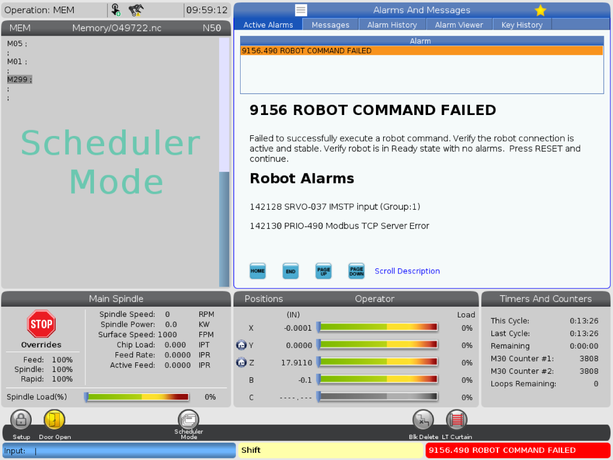
- 9156.037 SRVO-037 IMSTP入力(グループ:1)
- 9156.406 SRVO-406 DCS SSO SVOFF input 1,1
|
TB1-BおよびTB3-Bコネクタが間違った場所に差し込まれているか、差し込まれていません。 |
接続子を正しい位置に差し込みます。以下のSRVO-004フェンスオープンセクションを参照してください。 |
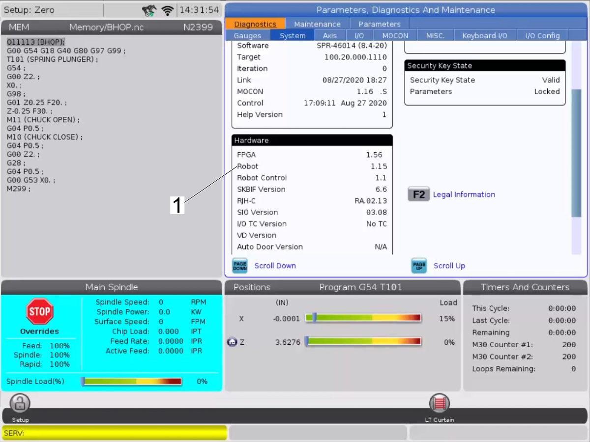
| 9156.035 ロボットコマンド障害SYST-035メインでのバッテリー電源が低またはゼロ |
原因:PSUボードのバッテリー残量が少なくなっています。 |
解決:古いバッテリーを同じ種類の新しいバッテリーに交換します。
詳細については、HRP制御バッテリーの交換手順を参照してください。
バッテリーの電圧が低下すると、低電圧バッテリーアラームのSYST-035が制御装置に表示されます。このアラームが表示されたら、できるだけ早くバッテリーを交換します。一般的に、バッテリーは1〜2週間で交換できますが、これはシステム構成によって異なります。バッテリー電圧が低下すると、SRAMの内容をバックアップすることができなくなります。緊急時には、重要なデータを事前にメモリカードまたはその他の外部デバイスに保存する必要があります。
|
| 9156.050 ロボットコマンド故障SRVO-050衝突検出アラーム |
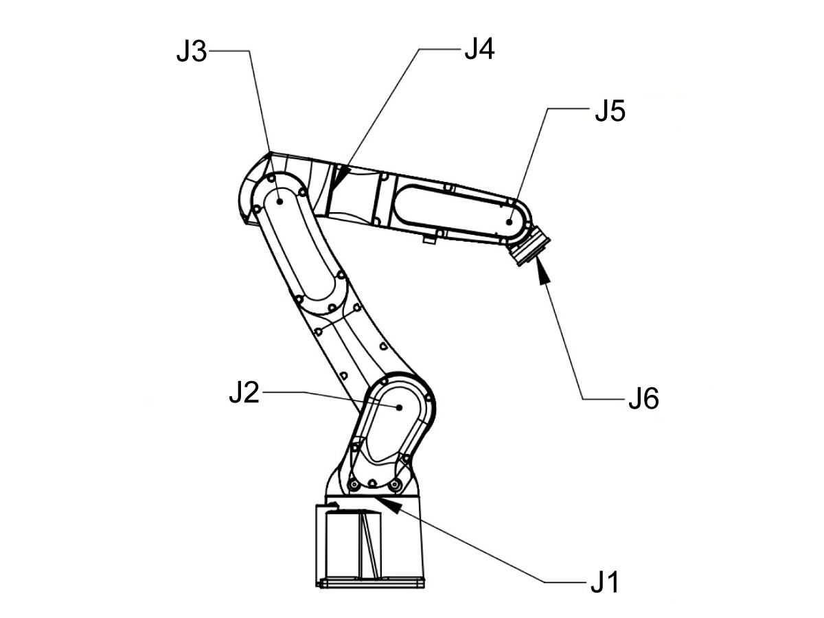
セットアップモードでロボットをジョグすると、J6の回転中心はJ4の回転中心と一致します。次に、WまたはPを回転させると、J4軸が非常に速い速度で回転しようとします。この特異点は手首の特異点と呼ばれます。 |
RESET(リセット)を押してアラームを消します。この特異点を介してロボットをジョグしないでください。 |
| ロボットモーションファイルには、滑らかでない動きを生じるような点があまりありません。 |
モーションファイルに点を追加して、ロボットの滑らかな動きを弱くします。 |
| 9156.406 SRVO-406 DCS SSO SVOFF input 1,1 |
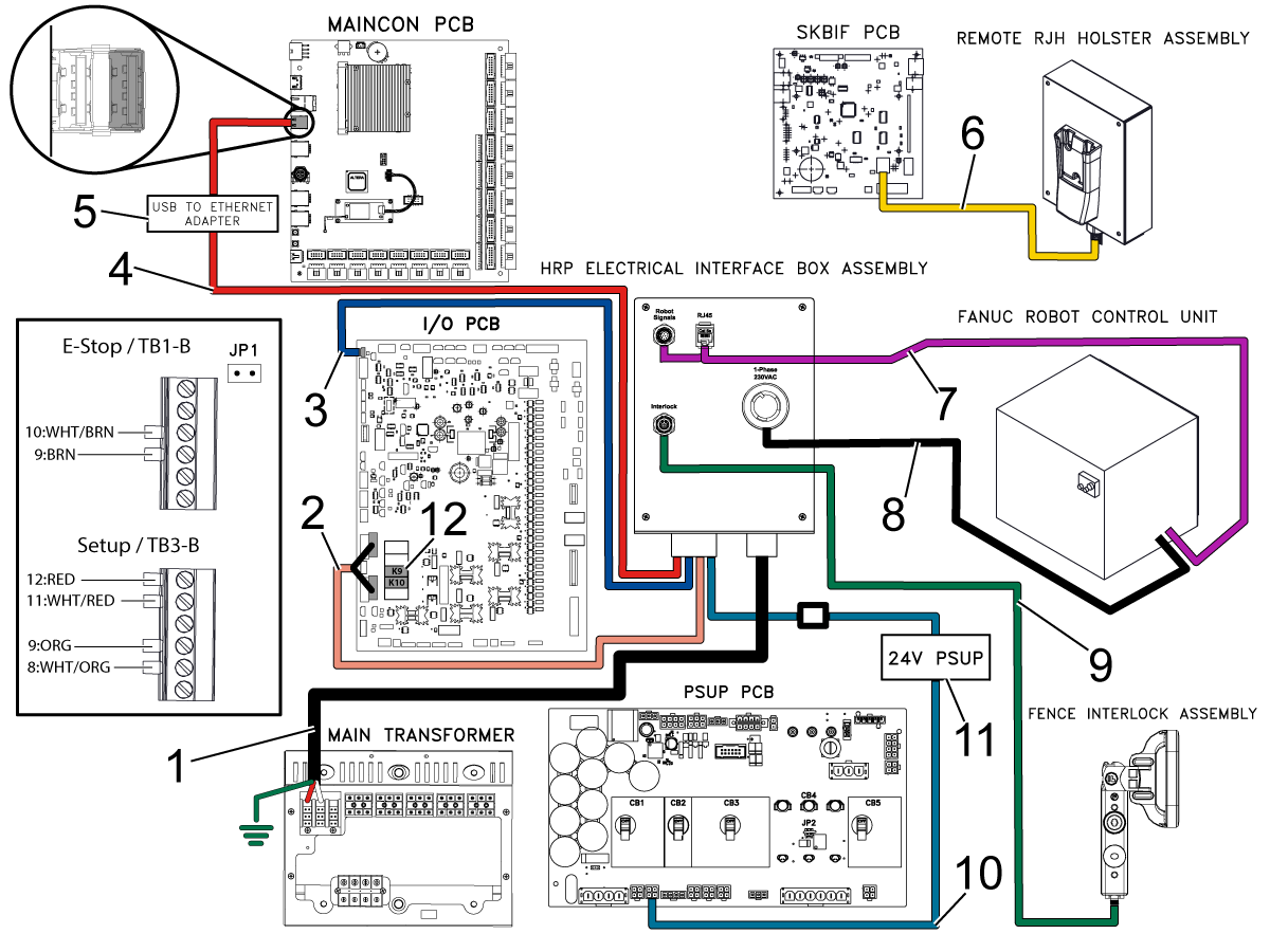
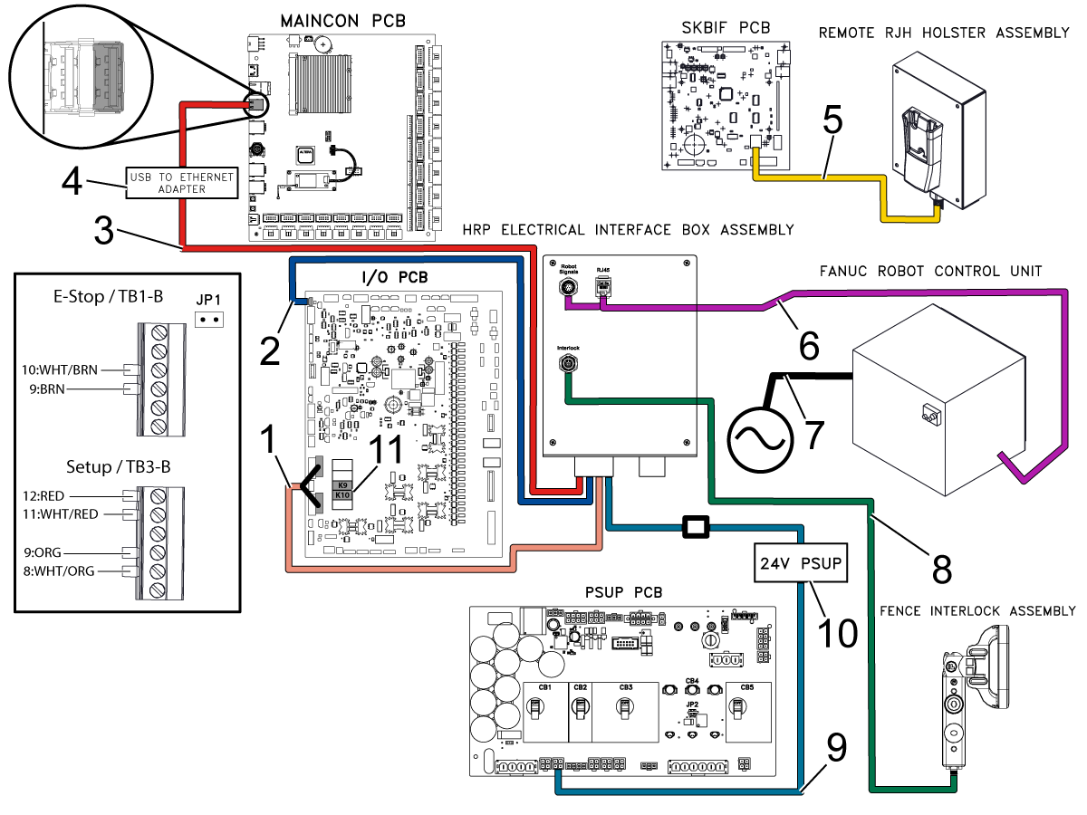
I/O PCB上のK9およびK10リレーが取り付けられていません。 |
K9およびK10リレーがI/O PCBに取り付けられていることを確認してください。「ロボット設置手順、電気」のセクションを参照してください。 |
| フェンスが実行モードで開いています。 |
インターロックが機能していて、その機械がインターロック入力信号を受信していることを確認してください。 |
| TB3-Bの配線が破損しているか、配線が間違っています。 |
TB3-Bコネクタの配線を確認してください。コネクタの配線を配線図と比較してください。 |
| DCSデカルト位置チェックゾーンがセットアップされていません。 |
DCSデカルト位置チェックゾーン手順に従ってください。 |
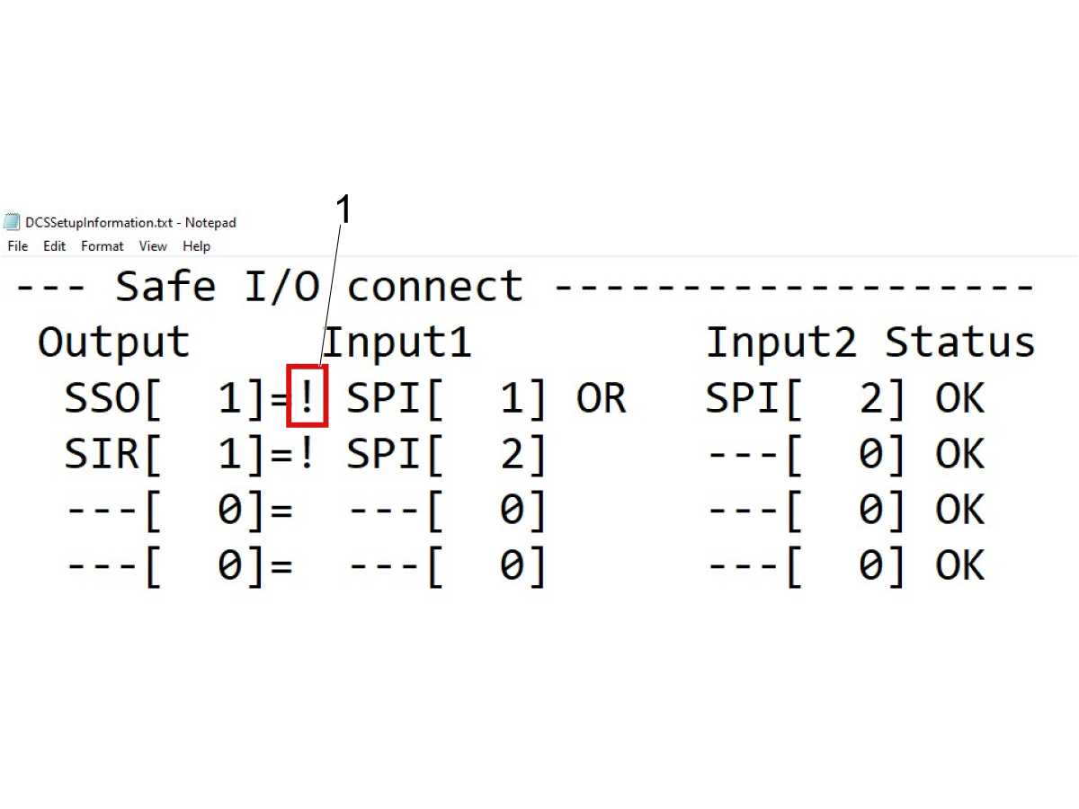
| 入力1の安全I/Oが正しく設定されていません。 |
以下の安全I/O入力1の手順に従ってください。 |
| 9156.037 SRVO-037 IMSTP入力(グループ:1) |
TB3-Bの配線が破損しているか、配線が間違っています。 |
TB-3Bコネクタの配線を確認してください。コネクタの配線を配線図と比較してください。 |
| 9156.062 ROBOT COMMAND FAILED SRVO-062 BZALアラーム |
ロボットアームの電池が切れました。 |
HRP - バッテリーの交換手順に従い、電池を交換し、HRP - クイックマスタリング 手順に従い、ロボットをリマスターします。 |
| 9156.115 SRVO-115制限エラー(動作グループ番号、軸番号) |
線形経路は軸の範囲外を通過します。 |
軸を移動制限の中央位置で記録するため、プログラムポイントを再び指示するか、ジョイント位置を使用してください。 |
9156.378 FANUC ROBOT ALARM (FANUC ロボットアラーム)- SFDI12 ステータス異常
または
9156.378 FANUC ROBOT ALARM (FANUC ロボットアラーム)- SFDI22 ステータス異常
|
I/O PCB上のK9およびK10リレーが取り付けられていません。 |
K9およびK10リレーがI/O PCBに取り付けられていることを確認してください。「ロボット設置手順、電気」のセクションを参照してください。 |
| SFDI信号でチェーン アラームが検出されました。 |
チェーンエラーが検出された場合は、アラームの原因を修正してから、以下のチェーンエラーのリセットセクションを参照してください。 |
9156.230 FANUC ROBOT ALARM - チェーン1の異常 a,b
または
9156.231 FANUC ROBOT ALARM - チェーン2異常 a,b
|
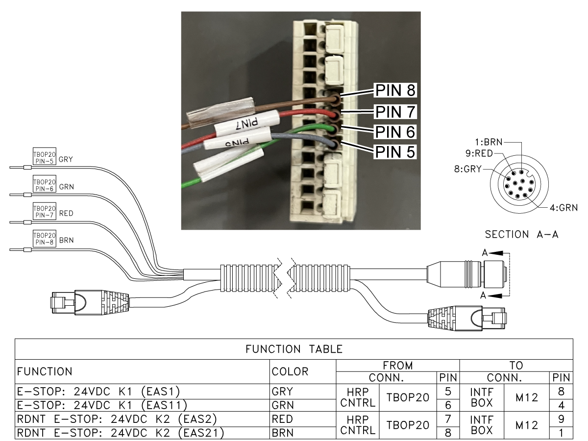
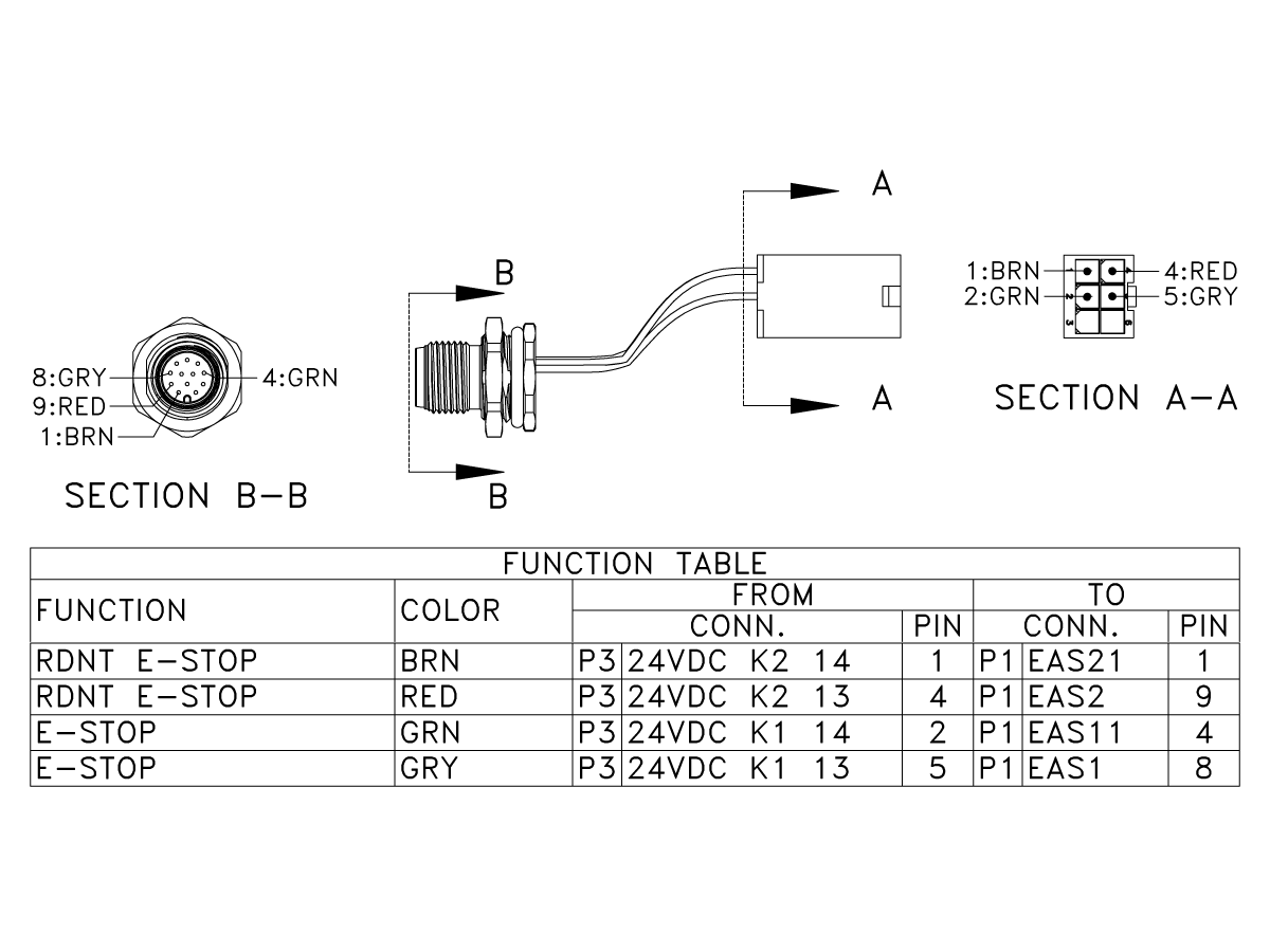
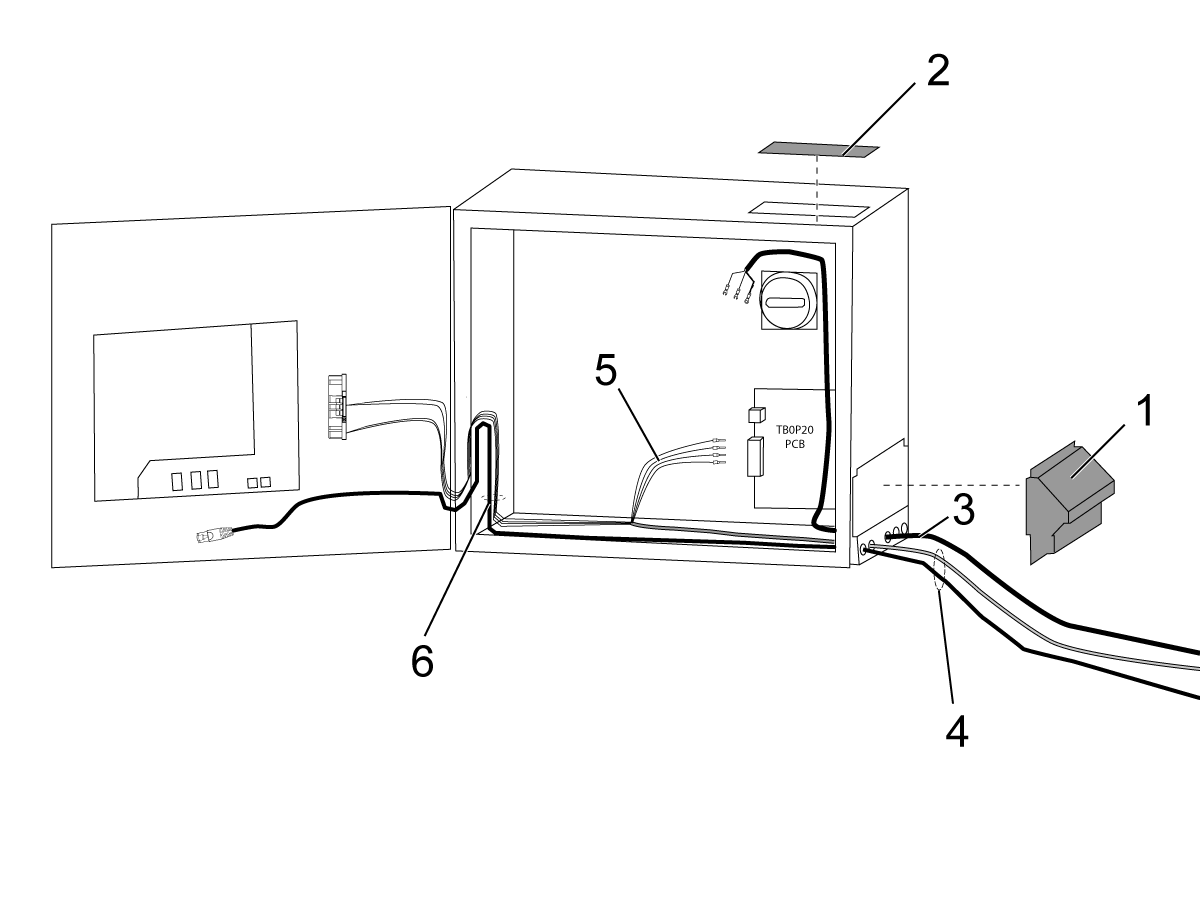
TBOP20ワイヤーまたはコネクタの損傷または配線ミス。
二重の安全信号間で不一致が発生しました。SRVO-230は、チェーン1側(EAS1とEAS11間)の接点が閉じており、チェーン2側(EAS2とEAS21間)の接点が開いているというような不一致が起こった場合に発生します。SRVO-231は、チェーン1側の接点が開いていて、チェーン2側の接点が閉じているという不一致が発生した場合に発行されます。
|
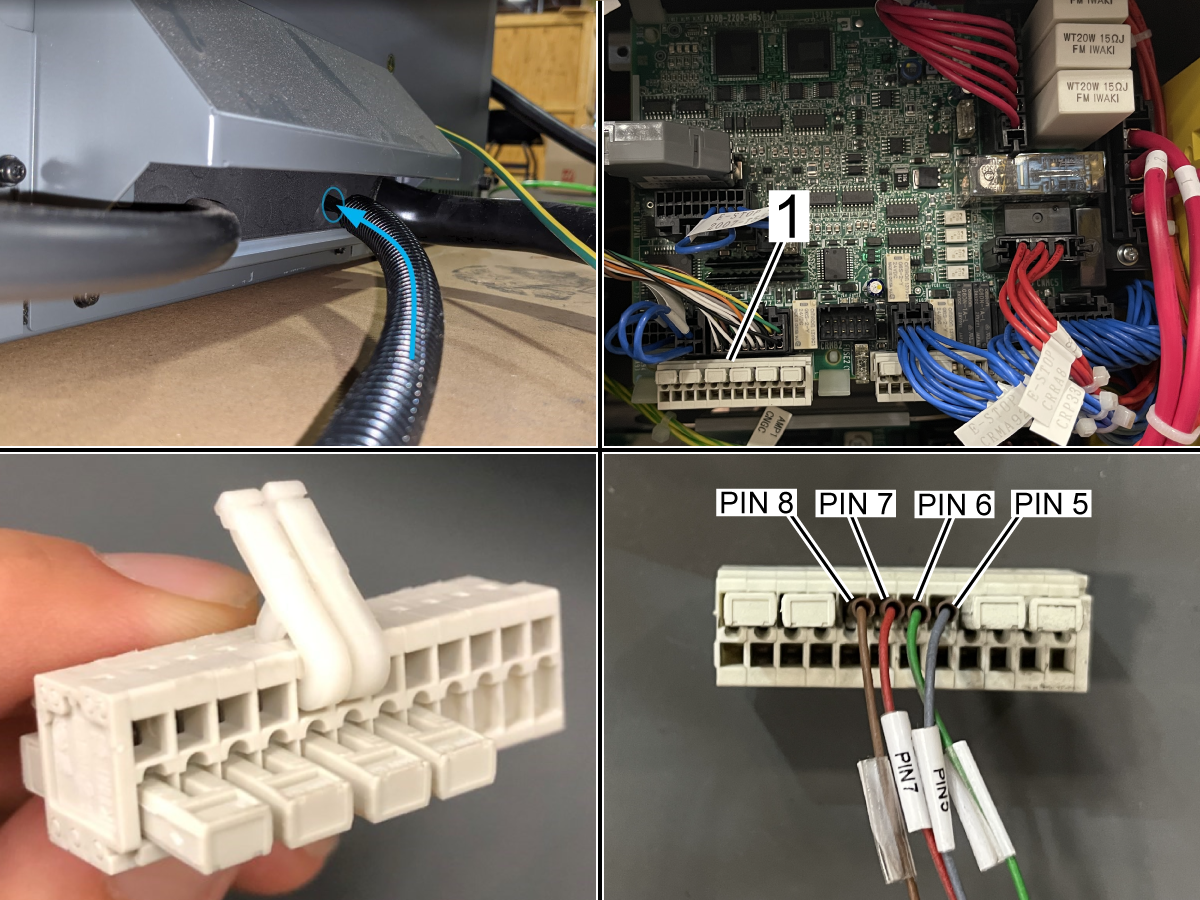
フェンス用の信号ケーブルに損傷や誤配線がないか確認してください。Fanuc制御ボックスまたはインターフェースボックスM12コネクタのロボット信号におけるTBOP20コネクタとケーブル。以下のSRVO-230/231/266/267 フェンス1/2ステータスの異常セクションを参照してください。
アラームの原因を修正してから、以下のリセットチェーンのエラーセクションを参照してください。
|
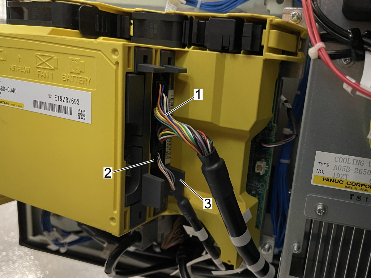
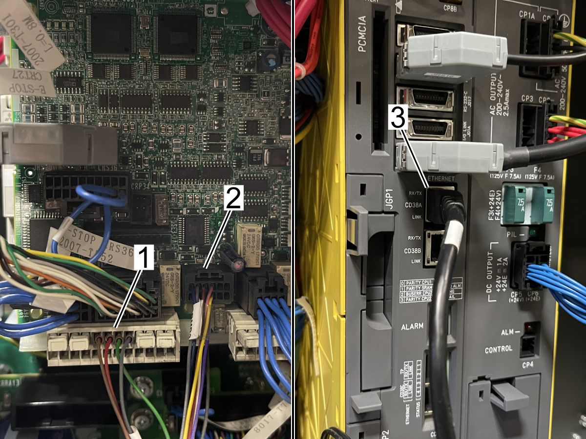
9156.217 SRVO-217 非常停止ボードが見つかりません
または
- 9156.037 SRVO-037 IMSTP入力(グループ:1)
- 9156.406 SRVO-406 DCS SSO SVOFF input 1,1
- 9156.217 SRVO-217 非常停止ボードが見つかりません
|
このアラームは、非常停止PCBまたは安全I/O PCBのいずれかが安全バスにない場合に生成されます。 |
HRP-1:
安全I/O PCBが完全に取り付けられていることを確認します。ケーブルが非常停止PCBと安全I/OPCBに接続されていることを確認します。
HRP-2/3:
ケーブルJRS20が非常停止PCBとメインボードに完全に固定されていることを確認してください。
ヒューズ1が完全に固定され装着され、故障していないことを確認します。ヒューズ1 A60L-0001-0290/LM10Cは、93-3378にあります。
ケーブルCRP33が非常停止PCBに完全に固定されていることを確認します。
|
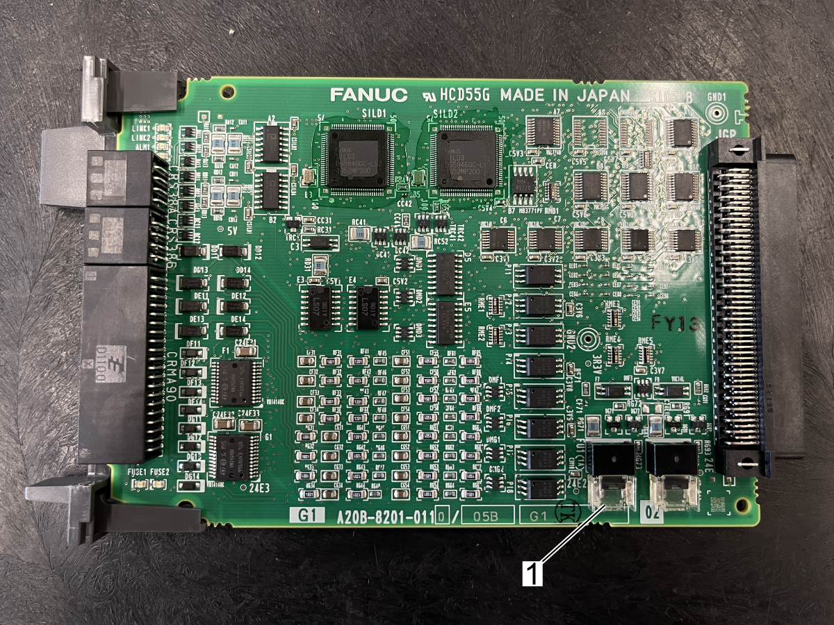
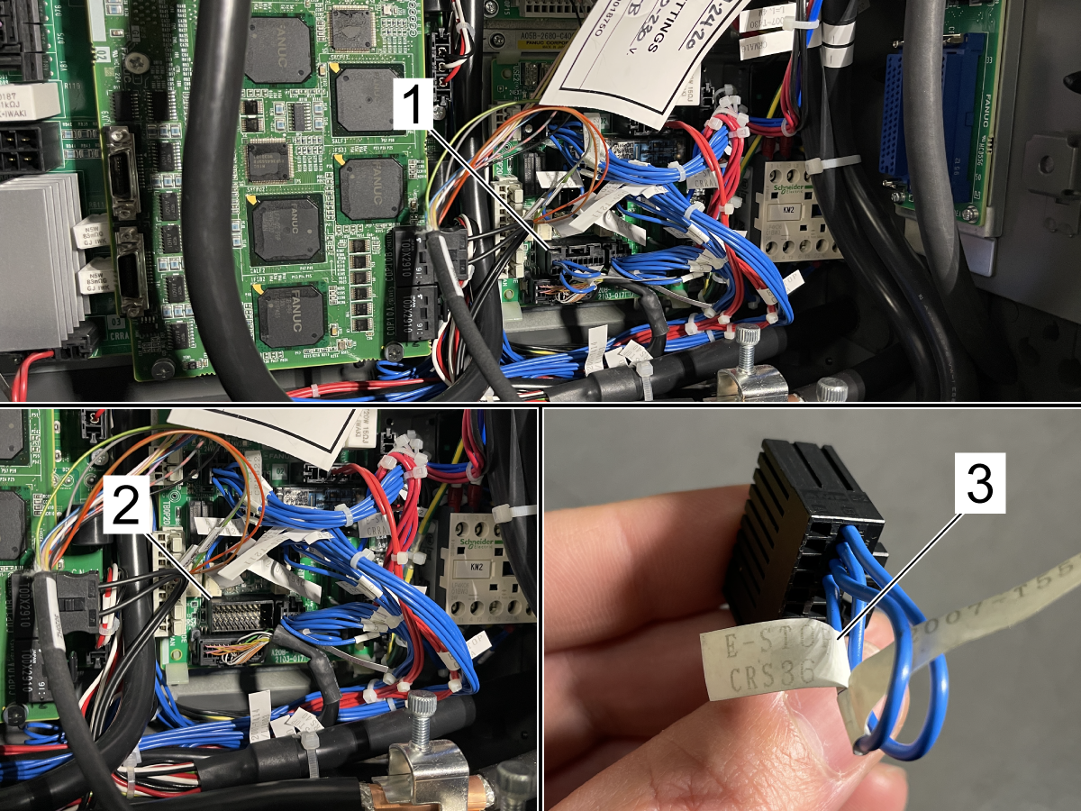
| 9156.219 SRVO-219安全I/Oボードヒューズ%d切れ%s |
ロボットコマンドを正常に実行できませんでした。追加の安全I/Oボードのヒューズが飛んでいます。TB1-BまたはTB3-B配線が損傷しているか、配線が間違っているか、間違った場所に差し込まれています。 |
アラームが発生した安全I/O装置番号は、メッセージの最後に表示されます(例:(1)など)。安全I/O装置番号は、DCS安全I/O装置のメニューに表示されます。配線の問題を修正してください。増設安全I/Oボードまたは増設安全I/Oボードのヒューズを交換してください。以下のヒューズ交換セクションを参照してください。 |
| 9156.266 SRVO-266 FENCE1ステータス異常 |
TBOP20ワイヤーまたはコネクタの損傷または配線ミス。
二重の安全信号間で不一致が発生しました。SRVO-266は、チェーン1側(EAS1とEAS11間)の接点が閉じており、チェーン2側(EAS2とEAS21間)の接点が開いているというような不一致が発生した場合に発行されます。SRVO-266は、チェーン1側の接点が開いていて、チェーン2側の接点が閉じているというような不一致が発生した場合に発行されます。
|
フェンス用の信号ケーブルに損傷や誤配線がないか確認してください。Fanuc制御ボックスまたはインターフェースボックスM12コネクタのロボット信号におけるTBOP20コネクタとケーブル。以下のSRVO-230/231/266/267 フェンス1/2ステータスの異常セクションを参照してください。
アラームの原因を修正してから、以下のリセットチェーンのエラーセクションを参照してください。
|
| 9156.267 SRVO-267 FENCE2ステータス異常 |
TBOP20ワイヤーまたはコネクタの損傷または配線ミス。
二重の安全信号間で不一致が発生しました。SRVO-266は、チェーン1側(EAS1とEAS11間)の接点が閉じており、チェーン2側(EAS2とEAS21間)の接点が開いているというような不一致が発生した場合に発行されます。SRVO-266は、チェーン1側の接点が開いていて、チェーン2側の接点が閉じているというような不一致が発生した場合に発行されます。
|
フェンス用の信号ケーブルに損傷や誤配線がないか確認してください。Fanuc制御ボックスまたはインターフェースボックスM12コネクタのロボット信号におけるTBOP20コネクタとケーブル。以下のSRVO-230/231/266/267 フェンス1/2ステータスの異常セクションを参照してください。
アラームの原因を修正してから、以下のリセットチェーンのエラーセクションを参照してください。
|
| 9156.289 SRVO-289 スムーズな停止 |
DCSゾーンが正しくセットアップされていません。デカルト速度チェック、ジョイント位置チェック、またはジョイント速度チェックを無効にすると有効になります。 |
無効にする手順については、以下のDCS速度チェックを無効にするセクションを参照してください。 |
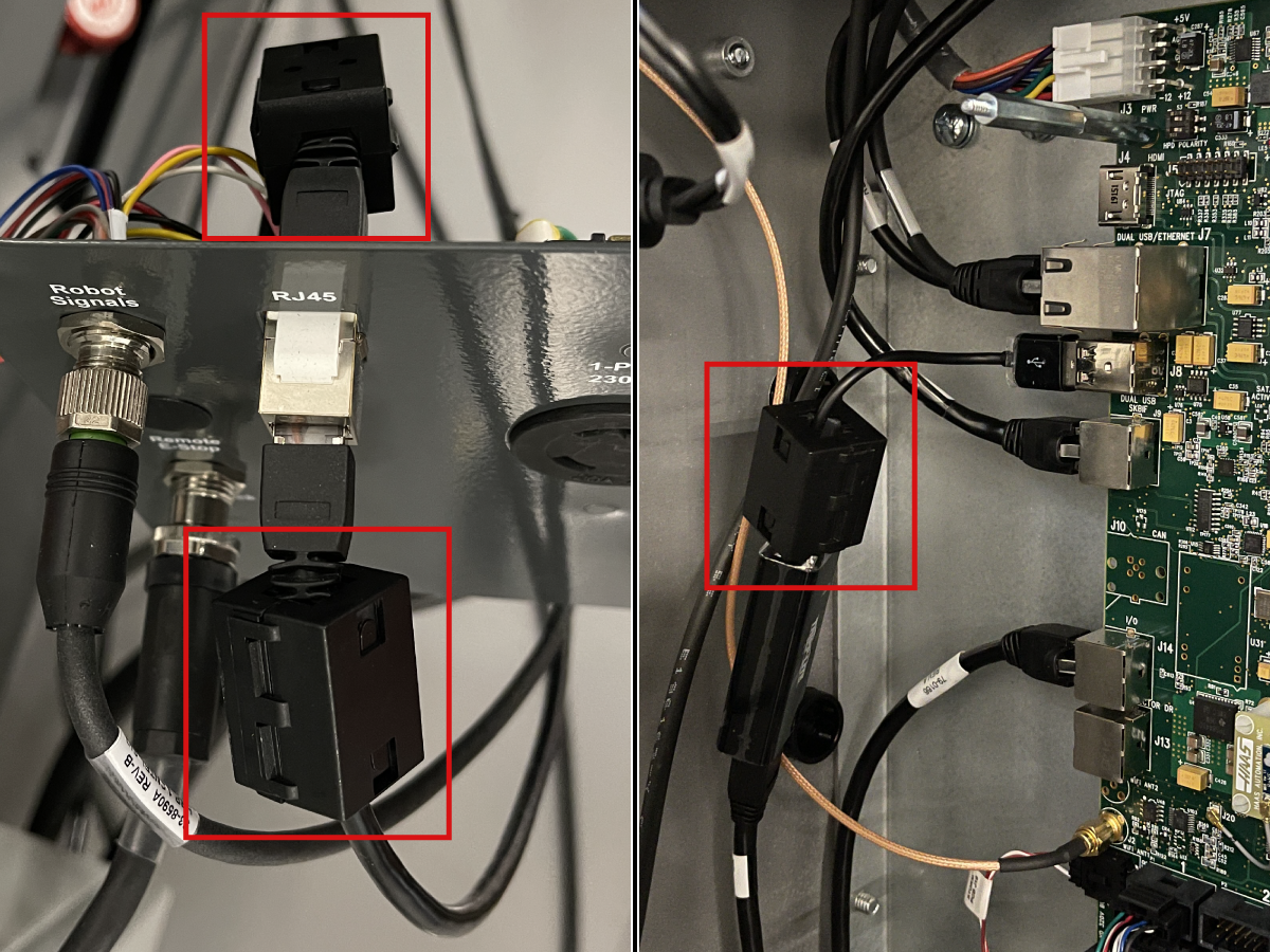
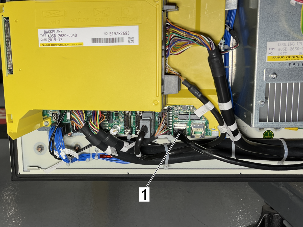
| 9156.490 PRIO-490 Modbus TCPサーバーエラー |
干渉またはRJ-45イーサネットケーブルの障害。 |
ロボットの組立日によっては、ケーブルにはフェライトフィルターが取り付けられた状態で組立てられていません。フェライトフィルターPN: 64-1252 を電気インターフェースボックスのRJ-45通信ケーブルとメインプロセッサPCBのUSB-イーサネットアダプタの両方に取り付けます。以下の「フェライトフィルター」セクションを参照してください。アラームが続く場合は、ケーブルをテストしてください。 ネットワークケーブルテスターツール 手順を参照してください。
ケーブルがネットワークケーブルテストに合格した場合は、以下のHRP不一致アラームセクションを参照して、Modbus TCPタイムアウトを増やし、DHCPを無効化してください。
|
| 9156.043 ロボットコマンドが失敗しました |
Fanucコントローラーのオペレーターパネルのモードスイッチは、ティーチペンダントが接続されていないときに、誤ってティーチングモードに設定されています。
|
モードスイッチを自動モードに切り替えます。 |


.png)
.png)