My Haas Welcome,
!
Haas Tooling MyHaas/HaasConnect Sign In Register Haas Tooling MyHaas/HaasConnect Sign Out Welcome, My Machines Latest Activity My Quotes My Account My Users Sign Out
Find Your Distributor
  1. Select Language
    1. English
    2. Deutsch
    3. Español - ES
    4. Español - MX
    5. Français
    6. Italiano
    7. Português
    8. Český
    9. Dansk
    10. Nederlands
    11. Magyar
    12. Polski
    13. Svenska
    14. Türkçe
    15. 中文
    16. Suomi
    17. Norsk
    18. الإنجليزية
    19. български
    20. Hrvatski
    21. Ελληνικά
    22. Română
    23. Slovenský
    24. Slovenščina
    25. 한국어
    26. 日本語
    27. Українська
  • machines Main Menu
    • Vertical Mills
      Vertical Mills
      Vertical Mills View All
      • Vertical Mills
      • VF Series
      • Universal Machines
      • VR Series
      • VP-5 Prismatic
      • Pallet-Changing VMCs
      • Mini Mills
      • Mold Machines
      • High-Speed Drill Centers
      • Drill/Tap/ Mill Series
      • Toolroom Mills
      • Pocket Mill
      • Compact Mills
      • Gantry Series
      • SR Sheet Routers
      • Extra-Large VMC
      • Double-Column Mills
      • 3+2 Positioning Machines
    • Multi-Axis Solutions
      Multi-Axis Solutions
      Multi-Axis Solutions View All
      • Multi-Axis Solutions
      • Y-Axis Lathes
      • 5-Axis Mills
    • Lathes
      Lathes
      Lathes View All
      • Lathes
      • ST Series
      • Dual-Spindle
      • Box Way Series
      • Toolroom Lathes
      • Chucker Lathe
      • Pocket Lathe
      • Haas Bar Feeders
    • Horizontal Mills
      Horizontal Mills
      Horizontal Mills View All
      • Horizontal Mills
      • 50-Taper
      • 40-Taper
    • Rotaries & Indexers
      Rotaries & Indexers
      Rotaries & Indexers View All
      • Rotaries & Indexers
      • Rotary Tables
      • Indexers
      • 5-Axis Rotaries
      • Extra-Large Rotaries
    • Special Series
      Special Series
      Special Series View All
      • Special Series
      • EU_Series_Redirect
    • Automation Systems
      Automation Systems
      Automation Systems View All
      • Automation Systems
      • Mill Automation
      • Lathe Automation
      • Automatic Parts Loaders
      • Automation Models
    • Desktop Machines
      Desktop Machines
      Desktop Machines View All
      • Desktop Machines
      • Desktop Mill
      • Desktop Lathe
      • Control Simulator, Standard
      • Control Simulator, Premium
    • Shop Equipment
      Shop Equipment
      Shop Equipment View All
      • Shop Equipment
      • Knee Mill
      • Haas Manual Lathes
      • Haas Saws
    • Fabrication Machines
      Fabrication Machines
      Fabrication Machines View All
      • Fabrication Machines
      • Laser Cutting Machines
      • CNC Press Brakes
    • QUICK LINKS Special Series  Special Series 
      EU SERIES EU SERIES BUILD & PRICE | PRICE LIST BUILD & PRICE | PRICE LIST In-Stock Machines In-Stock Machines WHAT’S NEW WHAT’S NEW YOUR FIRST CNC YOUR FIRST CNC
      SHOPPING TOOLS
      • Build & Price a Haas
      • Price List
      • Available Inventory
      • CNCA Financing
      WANT TO TALK TO SOMEONE?

      A Haas Factory Outlet (HFO) can answer your questions, and walk you through your best options.

      CONTACT YOUR DISTRIBUTOR >
  • Options Main Menu
    • The Haas Control Value Option Packages
      Value Option Packages
      Value Option Packages View All
      • Value Option Packages
    • Product Image Spindles
      Spindles
      Spindles View All
      • Spindles
    • Product Image Tool Changers
      Tool Changers
      Tool Changers View All
      • Tool Changers
    • Product Image 4th- | 5th-Axis
      4th- | 5th-Axis
      4th- | 5th-Axis View All
      • 4th- | 5th-Axis
    • Product Image Turrets & Live Tooling
      Turrets & Live Tooling
      Turrets & Live Tooling View All
      • Turrets & Live Tooling
    • Product Image Probing
      Probing
      Probing View All
      • Probing
    • Haas Chip & Coolant Management Chip & Coolant Management
      Chip & Coolant Management
      Chip & Coolant Management View All
      • Chip & Coolant Management
    • The Haas Control The Haas Control
      The Haas Control
      The Haas Control View All
      • The Haas Control
    • Product Image Product Options
      Product Options
      Product Options View All
      • Product Options
    • Product Image Tooling & Fixturing
      Tooling & Fixturing
      Tooling & Fixturing View All
      • Tooling & Fixturing
    • Product Image Workholding
      Workholding
      Workholding View All
      • Workholding
    • Product Image 5-Axis Solutions
      5-Axis Solutions
      5-Axis Solutions View All
      • 5-Axis Solutions
      • 5 Easy Steps to 5-Axis
    • QUICK LINKS Special Series  Special Series 
      EU SERIES EU SERIES BUILD & PRICE | PRICE LIST BUILD & PRICE | PRICE LIST In-Stock Machines In-Stock Machines WHAT’S NEW WHAT’S NEW YOUR FIRST CNC YOUR FIRST CNC
      SHOPPING TOOLS
      • Build & Price a Haas
      • Price List
      • Available Inventory
      • CNCA Financing
      WANT TO TALK TO SOMEONE?

      A Haas Factory Outlet (HFO) can answer your questions, and walk you through your best options.

      CONTACT YOUR DISTRIBUTOR >
  • Why Haas Main Menu
      Discover the Haas Difference
    • Why Haas
    • MyHaas
    • Education Community
    • Industry 4.0
    • Haas Certification
    • Customer Testimonials
  • Service Main Menu
      Welcome to Haas Service
      SERVICE HOME Operator’s Manuals How-To Procedures Troubleshooting Guides Preventive Maintenance Haas Parts Haas Tooling Videos
  • Videos Main Menu
  • Main Menu
    • View All
    • View All
    • View All
    • View All
      • HTEC Curriculum Support
      • Haas Value Option Packages (VOP) Journey
    • View All
      • Haas 10 kg Cobot Package
      • Cobot Kits
      • DC-1 Drill Center
      • CNC Sales News
      • Do More With Your Haas
    • View All
    • View All
      • contact-us-test
      • 4 - AUTOMATION SYSTEMS
      • Carousel-V2
      • expert test
      • Demo_Day_Trident-test
      • Link Test
      • image-sale-tag-test
      • article-list-test
      • Haas 25 kg Robot Package
      • test-algolia-page
    • View All
    • View All
    • View All
    • View All
      • calc-test
    • View All
    • QUICK LINKS Special Series  Special Series 
      EU SERIES EU SERIES BUILD & PRICE | PRICE LIST BUILD & PRICE | PRICE LIST In-Stock Machines In-Stock Machines WHAT’S NEW WHAT’S NEW YOUR FIRST CNC YOUR FIRST CNC
      SHOPPING TOOLS
      • Build & Price a Haas
      • Price List
      • Available Inventory
      • CNCA Financing
      WANT TO TALK TO SOMEONE?

      A Haas Factory Outlet (HFO) can answer your questions, and walk you through your best options.

      CONTACT YOUR DISTRIBUTOR >
  • Haas Tooling Main Menu
  • Haas Service Parts Main Menu

My Haas Welcome,
!
Haas Tooling MyHaas/HaasConnect Sign In Register Haas Tooling MyHaas/HaasConnect Sign Out Welcome, My Machines Latest Activity My Quotes My Account My Users Sign Out
Find Your Distributor
  1. Select Language
    1. English
    2. Deutsch
    3. Español - ES
    4. Español - MX
    5. Français
    6. Italiano
    7. Português
    8. Český
    9. Dansk
    10. Nederlands
    11. Magyar
    12. Polski
    13. Svenska
    14. Türkçe
    15. 中文
    16. Suomi
    17. Norsk
    18. الإنجليزية
    19. български
    20. Hrvatski
    21. Ελληνικά
    22. Română
    23. Slovenský
    24. Slovenščina
    25. 한국어
    26. 日本語
    27. Українська
×

Search Results

Web Pages

Images

    • <
    • 1
    • >

UMC-750 - Spindle Motor - Removal and Installation

Service Home How To Procedures UMC-750 - Spindle Motor - Removal and Installation
Recently Updated Last updated: 06/07/2022

UMC-750 - Spindle Motor - Removal and Installation


UMC-750 - Spindle Motor - Removal and Installation

- Jump to Section - 1. Introduction (1 step) 2. UMC-750 - Spindle Drive Removal Tool - Assembly (2 steps) 3. UMC-750 - Spindle Motor - Removal (13 steps) 4. UMC-750 - Spindle Motor - Installation (10 steps) 5. Conclusion Back to Top

Introduction

1

This procedure tells you how to remove and install the spindle motor in a UMC-750.

Tools Required:

  • UMC Spindle Removal Tool (P/N T-2191)
  • Magnetic-Spindle-Encoder Jumper (P/N T-2200)

UMC-750 - Spindle Drive Removal Tool - Assembly

1

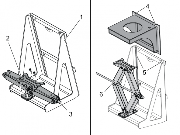
Put the lower frame [1] on the floor.

Attach the jack [2] to the lower frame with (4) screws. Align the jack so that the operation screw [3] faces to the right. Do not tighten the screws at this time.

Turn the jack operation screw [3]. Fully extend the jack [6].

Apply grease to both sides [4] of the upper frame.

Put the upper frame into the slots [5] on the lower frame. Move the upper frame down until it touches the top of the jack.

2

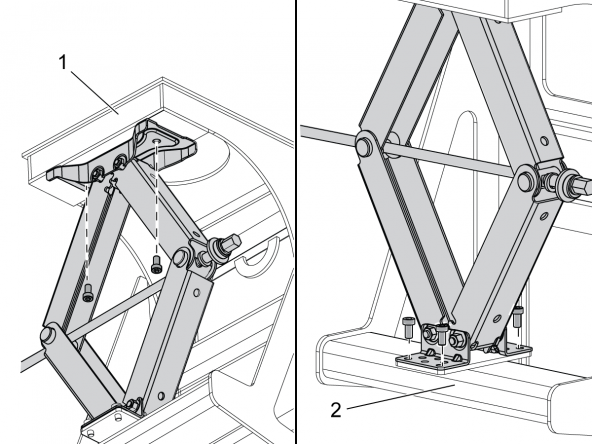
Attach the upper plate of the jack to the upper frame [1] with (2) screws. Do not tighten the screws at this time.

Visually align the front edge of the jack lower plate with the front edge of the lower frame [2]. Tighten the (4) lower screws. Visually align the jack with the front edge of the upper frame. Tighten the (2) upper screws.

UMC-750 - Spindle Motor - Removal

1

Zero return all axes.

Press E-STOP.

Remove the spindle head covers.

Caution: To remove the spindle head covers, you must jog the Z Axis several times. Make sure to push EMERGENCY STOP before you go into the machine.

Disconnect and remove these components:

  • Top casting support and the spindle fan
  • P-COOL assembly
  • Remote-tool-release cable
  • TSC supply hose
  • Vacuum generator hose
  • Hard coolant-tubing and nozzle assemblies
  • Spindle oil hose

Remove the bottom spindle enclosure panel.

2

Power off and then Lockout/Tagout the main circuit breaker.

 Danger: If the vector drive voltage indicator light is on, do not touch the electrical components. The high voltage in the control cabinet can kill you. Wait for the voltage indicator LED on the vector drive to go off completely.

 Caution: Use an electrostatic discharge strap when you handle electronic components.

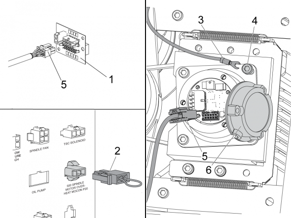
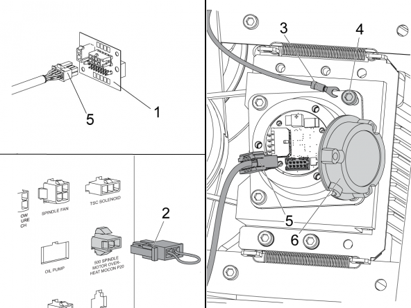
Connect a jumper (P/N 33-0819A) [2] to the connector with the label 500 SPINDLE MOTOR OVERHEAT MOCON P20 on the spindle connector-panel.

Remove the encoder cover [6].

Disconnect the encoder cable [5] from the terminal. Disconnect the ground cable [3].

Pull the encoder cable out of the spindle shroud and casting.

Connect the encoder cable [5] to the T-2200 [1]

Lightly tighten the ground cable screw [4].

Replace the encoder cover [6].

3

Disconnect the hoses connected to the bearingless union [2]. Remove the bearingless union [2].

Remove the (4) motor-shroud screws [1] from the motor lift brackets. Do not remove the brackets.

4

Release the EMERGENCY STOP.

Jog the X Axis to the center of travel.

Jog the Y Axis to the operator-end of travel.

Press EMERGENCY STOP.

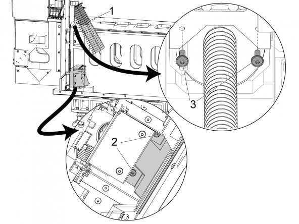
Remove the (2) bottom screws [2] from the front of the Y-Axis top cover. This releases the bottom of the Z-Axis bellows.

Tilt the Z-Axis bellows [1] towards the rear of the machine.

Remove the (2) screws [2] from the top cover for the Z-Axis bellows.

5

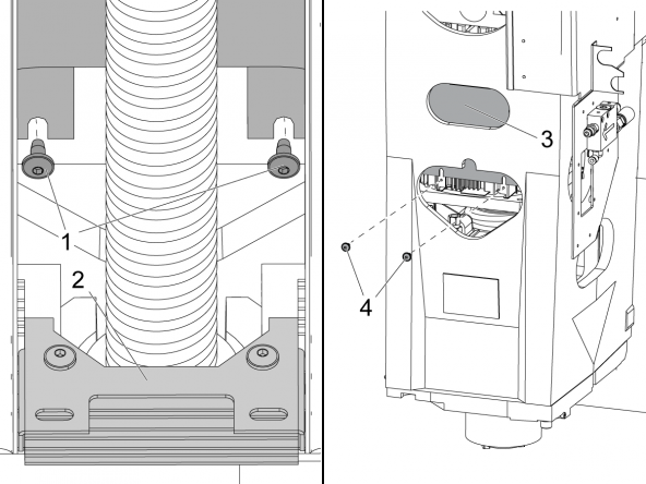
Push the Z-Axis bellows [2] down until you can reach the screws [1] for the motor shroud. Remove the screws.

Push POWER OFF.

Set the main circuit breaker to the OFF position.

Lock the main circuit breaker. Use an approved lock with an approved safety tag.

Remove the (2) lower screws [4] from the spindle junction box.

Slide the junction box cover [3] up to expose the (2) front motor shroud screws.

6

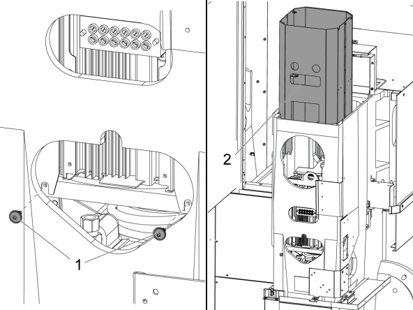
Remove the (2) front of the motor shroud screws [1].

Remove the motor shroud [2].

Remove the (2) motor lift-brackets.

7

Unlock the main circuit breaker. Press POWER ON.

Release the EMERGENCY STOP.

Jog the C Axis to 90 degrees.

Press EMERGENCY STOP.

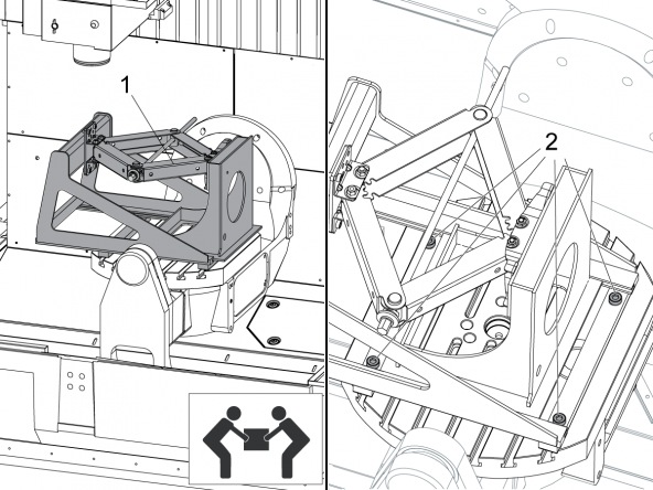
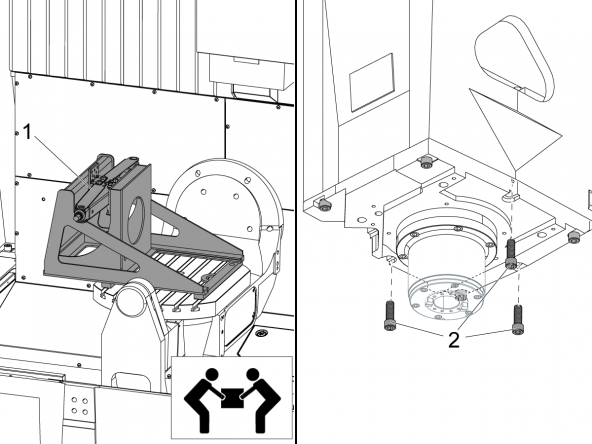
Put the spindle removal tool (SRT) [1] onto the platter.

Align the SRT parallel with the table slots, to make the jack screw face you.

 Caution: The SRT is heavy. Do not lift it into the UMC without the aid of another person.

Attach the SRT to the table with (4) T-slot screws [4].

Tighten the screws.

Turn each screw 1/4 turn in the counter-clockwise direction.

8

Release the EMERGENCY STOP.

Slowly jog the B Axis to -90 degrees.

 Caution: Make sure that the bottom edge of the SRT has sufficient clearance between the probe assembly and the floor sheet metal. Jog the C Axis a small distance to give sufficient clearance.

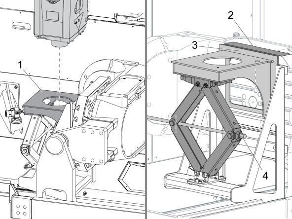
Jog the spindle until it is centered over the SRT [1].

Press EMERGENCY STOP.

Tighten the (4) T-slot screws.

Turn the jack actuating screw [4] to raise the top SRT frame.

Align the top edge of the frame [3] with the edge of the platter [2].

9

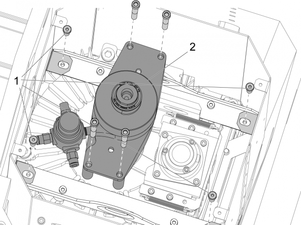
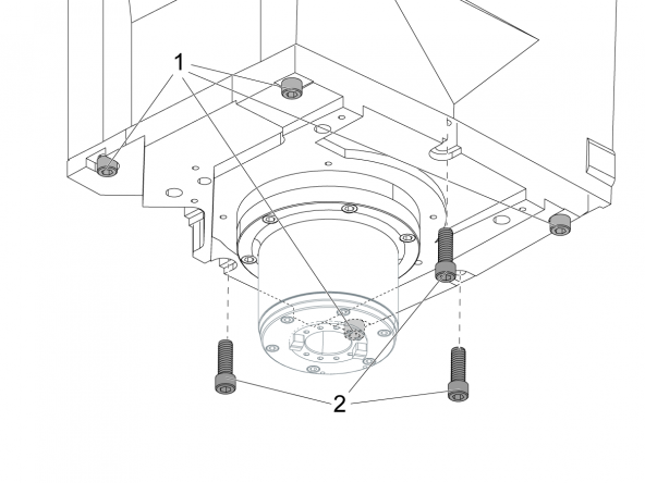
Remove the (3) center screws [2] for the spindle motor assembly.

Loosen the (4) remaining spindle motor assembly screws [1].

Caution: Do not remove the (4) screws [1].

10

Release the EMERGENCY STOP.

Slowly jog Z Axis in the negative (-) direction until the spindle touches the SRT frame.

Press EMERGENCY STOP.

Record the X, Y, and Z Axis positions. Use these during the installation procedure.

Put the anchor screw [1] through the bottom of the top SRT frame. Attach it to the bottom of the head casting.

11

Push POWER OFF.

Set the main circuit breaker to the OFF position.

Lock the main circuit breaker. Use an approved lock with an approved safety tag.

Danger: After turning off the machine, wait at least 5 minutes to allow power to dissipate before disconnecting the spindle-motor cables. Wait for the voltage indicator LED on the vector drive to go off completely.

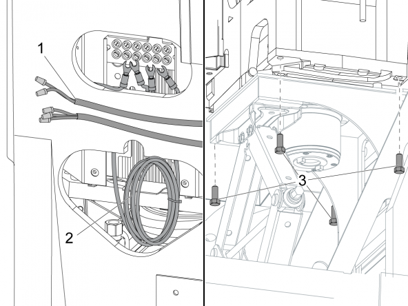
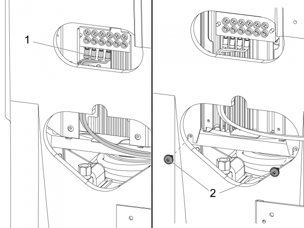
Disconnect the spindle-motor cables from the terminal block.

Pull the motor wires [1] out of the casting.

Wrap the smaller wires [2] into a coil below the junction box.

Put wire nuts on the motor wires.

Remove the (4) remaining screws [3] for the spindle motor assembly.

12

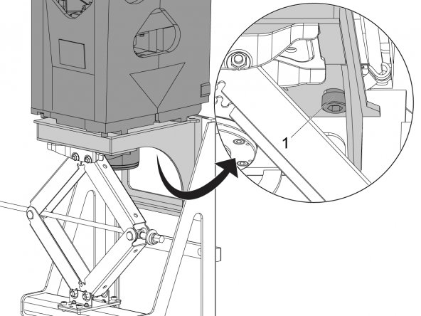
Slowly turn the jack screw [1] to lower the spindle motor assembly out of the head casting.

Turn the actuating screw until the jack is at the bottom of its travel.

Caution: Stop immediately if the jack screw becomes difficult to turn. Make sure to clear the obstacles that block the spindle motor assembly.

Set the main circuit breaker to the ON position.

Push POWER ON.

Release the EMERGENCY STOP.

Jog the Y and Z Axes to return the spindle [2] to the Home position.

Jog the X Axis to the end of travel, adjacent to the tool changer.

Press EMERGENCY STOP.

13

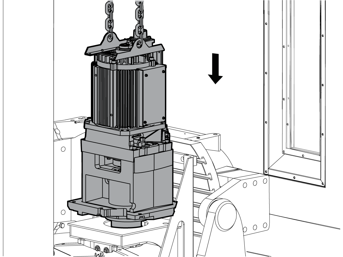
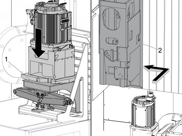
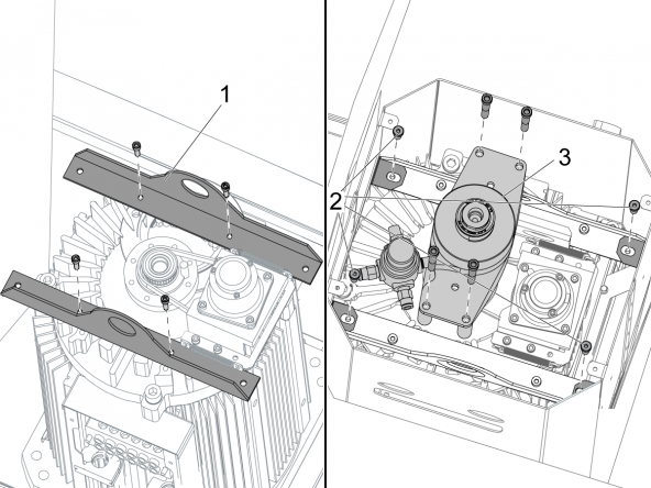
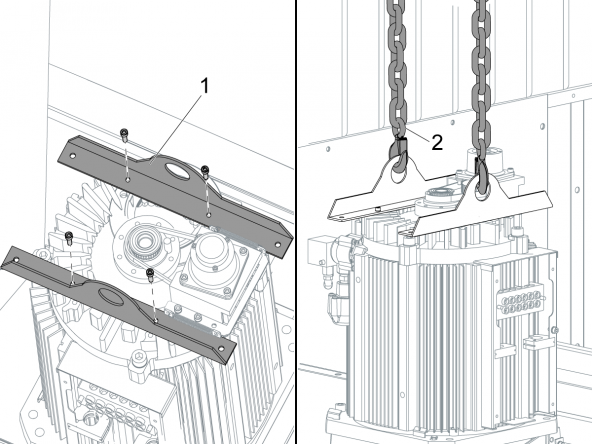
Attach the lift plates [1] to the top of the spindle motor.

Attach the chains [2] from a hoist to the lift plates.

Caution: The spindle motor assembly weighs a minimum of 112 lb (55 kg). Make sure to use a hoist that is sufficient for the weight of the spindle motor assembly.

Remove the SRT anchor-screw from the spindle motor through the SRT frame.

Lift the spindle motor assembly from the machine.

UMC-750 - Spindle Motor - Installation

1

  • Press EMERGENCY STOP.
  • Turn the jack actuating screw to raise the top SRT frame until it is even with the top of the table (See Step 8 of the "Removal" section above).
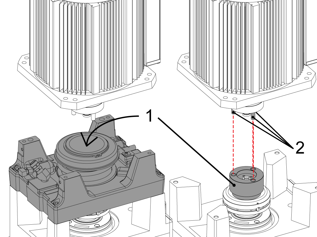
  • Use a hoist to position the spindle motor assembly centered over the TRP.
  •  Caution: The spindle motor assembly weighs more than 112 lb (55 kg). Use a hoist that is sufficient for the weight of the spindle motor assembly. Do not attempt to install the motor by hand.
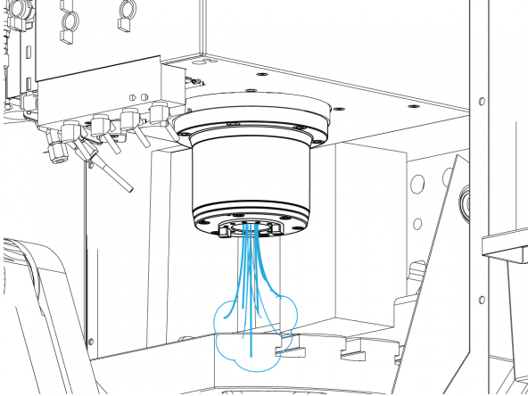
  • When lowering the motor onto the rest of the spindle assembly, be sure to align the 3 pins of the male side of the coupler [2] to the respective holes of the female side of the coupler [1] that can be seen below the TRP sub assembly. Rotate the male side by hand to adjust alignment. 
  •  Warning: Damage will occur if the coupler is not aligned properly.
  • Do not remove or adjust the TRP.

2

Fully clean the mating surfaces for the spindle motor assembly and the head casting. Use a fine stone to make sure the mating surfaces are smooth.

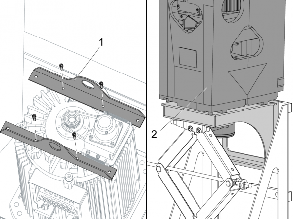
Remove the lift plates [1] from the top of the spindle motor.

Release the EMERGENCY STOP.

Jog the X, Y, and Z Axes to the positions recorded at Step 11 of the "UMC-750 - Spindle Motor - Removal" procedure.

Press EMERGENCY STOP.

Turn the jack actuating screw to raise the top SRT frame until it is even with the top of the table. The spindle motor assembly goes into the head casting [2].

Release the EMERGENCY STOP.

Slowly jog the Z Axis down until the head casting is a small distance from the spindle motor assembly plate.

Press EMERGENCY STOP.

3

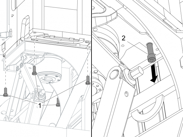
Insert the (4) corner screws [1] for the spindle motor assembly.

Do not tighten the screws.

Release the EMERGENCY STOP.

Jog the Z Axis down until the head casting aligns with the spindle motor assembly plate.

Press EMERGENCY STOP.

Tighten the (4) screws.

Remove the anchor screw [2] from under the SRT top frame

4

Turn the jack screw to lower the top SRT frame to the bottom of its travel.

Release the EMERGENCY STOP.

Jog the B Axis to -90 degrees.

Turn the B Axis 90 degrees in the negative (-) direction.

Remove the SRT.

Caution: Prevent damage to the machine. Make sure that the bottom edge of the SRT has sufficient clearance between the probe assembly and the floor sheet metal. Jog the C Axis a small distance to give sufficient clearance.

 Caution: The SRT is heavy. Do not lift it out of the UMC without the aid of another person.

Press EMERGENCY STOP.

Install the (3) remaining screws [3] for the spindle motor assembly.

Release the EMERGENCY STOP.

Jog the Z Axis to the Home position.

Press EMERGENCY STOP.

Torque the (7) spindle-motor screws. Refer to Haas Fastener Torque Specifications. Use the value for iron.

5

Release the EMERGENCY STOP.

Jog the Y Axis to the end of travel at the front of the machine.

Jog the X Axis to the center of travel.

Jog the Z Axis to the bottom end of travel.

Press EMERGENCY STOP.

Install the (2) lifting brackets [1].

Insert the motor shroud into the head casting.

Attach the (4) motor shroud screws [2].

Install the bearingless coolant-union [3] to the top of the spindle motor assembly

6

Power off and then Lockout/Tagout the main circuit breaker.

Danger: If the vector drive voltage indicator light is on, do not touch the electrical components. The high voltage in the control cabinet can kill you. Wait for the voltage indicator LED on the vector drive to go off completely.

Caution: Use an electrostatic discharge strap when you handle electronic components.

Disconnect the spindle encoder cable [5] from the T-2200 [1].

Remove the jumper [2] from the connector on the spindle connector panel that has the label 500 SPINDLE MOTOR OVERHEAT MOCON P20. Connect the overheat cable for the spindle motor.

Connect the encoder cable [5].

Connect the ground wire [3] to the screw for the ground wire [4].

7

Connect the spindle motor cables [1] to the terminal block in the junction box. The cable connections have labels.

Attach the (2) front motor shroud screws [2].

Move the junction-box cover down.

Tighten the junction-box cover with (2) screws.

8

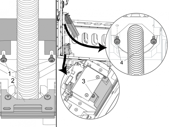
Attach the (2) rear motor cover shroud screws [1].

Lift the Z-Axis bellows [2] to the top of the column.

Attach the top (2) screws [3] for the Z-Axis bellows.

Slide the Y-Axis inside way cover all the way forward. Reach inside the rear of the column to install the (2) screws [4] that hold it in position.

9

Install these components:

  • Bottom spindle enclosure panel
  • Top casting support and the spindle fan
  • P-COOL assembly
  • Remote-tool-release cable
  • TSC supply hose
  • Vacuum generator hose
  • Hard coolant-tubing and nozzle assemblies
  • Spindle oil hose

10

Unlock the main circuit breaker and press POWER ON.

Press AUX CLNT to test the TSC system.

Make sure there are no coolant leaks at the spindle head.

Conclusion

After replacing the spindle motor you must perform the following procedures.

Set Spindle Orientation Offset
Set Parameter 64 Z-axis tool change offset
Set x and y axes tool change offsets
wireless intuitive probing system (wips) calibration

Recently Viewed Items

You Have No Recently Viewed Items Yet

Feedback
Haas Logo

Haas Delivered Price

This price includes shipping cost, export and import duties, insurance, and any other expenses incurred during shipping to a location in France agreed with you as a buyer. No other mandatory costs can be added to the delivery of a Haas CNC Product.

KEEP UP WITH THE LATEST HAAS TIPS AND TECHNOLOGY...

Sign up now!   

HAAS TOOLING ACCEPTS THE FOLLOWING:

  • Service & Support
  • Owners
  • Request Service
  • Operator Manuals
  • Haas Parts
  • Rotary Repair Request
  • Pre-Install Guides
  • Shopping Tools
  • Build & Price a New Haas
  • Available Inventory
  • The Haas Price List
  • CNCA Financing
  • About Haas
  • Accessibility Statement
  • DNSH Statement
  • Export Compliance
  • Careers
  • Certifications & Safety
  • Contact Us
  • History
  • Terms & Conditions
  • Haas Tooling Terms & Conditions
  • Privacy
  • Warranty
  • Haas Community
  • Haas Certification Program
  • Haas Motorsports
  • Gene Haas Foundation
  • Haas Technical Education Community
  • Events
  • Join the Conversation
  • Facebook
  • X
  • Flickr
  • YouTube
  • LinkedIn
  • Instagram
  • TikTok
© 2026 Haas Automation, Inc – CNC Machine Tools
This site is protected by reCAPTCHA and the Google Privacy Policy and Terms of Service apply.

2800 Sturgis Rd., Oxnard, CA 93030
Toll Free: (888) 817-4446 / Fax: 805-278-8554