My Haas Welcome,
!
Haas Tooling MyHaas/HaasConnect Sign In Register Haas Tooling MyHaas/HaasConnect Sign Out Welcome, My Machines Latest Activity My Quotes My Account My Users Sign Out
Find Your Distributor
  1. Select Language
    1. English
  • machines Main Menu
    • Vertical Mills
      Vertical Mills
      Vertical Mills View All
      • Vertical Mills
      • VF Series
      • Universal Machines
      • VR Series
      • VP-5 Prismatic
      • Pallet-Changing VMCs
      • Mini Mills
      • Mold Machines
      • High-Speed Drill Centers
      • Drill/Tap/ Mill Series
      • Toolroom Mills
      • Pocket Mill
      • Compact Mills
      • Gantry Series
      • SR Sheet Routers
      • Extra-Large VMC
      • Double-Column Mills
      • 3+2 Positioning Machines
    • Multi-Axis Solutions
      Multi-Axis Solutions
      Multi-Axis Solutions View All
      • Multi-Axis Solutions
      • Y-Axis Lathes
      • 5-Axis Mills
    • Lathes
      Lathes
      Lathes View All
      • Lathes
      • ST Series
      • Dual-Spindle
      • Box Way Series
      • Toolroom Lathes
      • Chucker Lathe
      • Pocket Lathe
      • Haas Bar Feeders
    • Horizontal Mills
      Horizontal Mills
      Horizontal Mills View All
      • Horizontal Mills
      • 50-Taper
      • 40-Taper
    • Rotaries & Indexers
      Rotaries & Indexers
      Rotaries & Indexers View All
      • Rotaries & Indexers
      • Rotary Tables
      • Indexers
      • 5-Axis Rotaries
      • Extra-Large Rotaries
    • Special Series
      Special Series
      Special Series View All
      • Special Series
      • EU_Series_Redirect
    • Automation Systems
      Automation Systems
      Automation Systems View All
      • Automation Systems
      • Mill Automation
      • Lathe Automation
      • Automatic Parts Loaders
      • Automation Models
    • Desktop Machines
      Desktop Machines
      Desktop Machines View All
      • Desktop Machines
      • Desktop Mill
      • Desktop Lathe
      • Control Simulator, Standard
      • Control Simulator, Premium
    • Shop Equipment
      Shop Equipment
      Shop Equipment View All
      • Shop Equipment
      • Knee Mill
      • Haas Manual Lathes
      • Haas Saws
    • Fabrication Machines
      Fabrication Machines
      Fabrication Machines View All
      • Fabrication Machines
      • Laser Cutting Machines
      • CNC Press Brakes
    • QUICK LINKS Special Series  Special Series 
      EU SERIES EU SERIES BUILD & PRICE | PRICE LIST BUILD & PRICE | PRICE LIST In-Stock Machines In-Stock Machines WHAT’S NEW WHAT’S NEW YOUR FIRST CNC YOUR FIRST CNC
      SHOPPING TOOLS
      • Build & Price a Haas
      • Price List
      • Available Inventory
      • CNCA Financing
      WANT TO TALK TO SOMEONE?

      A Haas Factory Outlet (HFO) can answer your questions, and walk you through your best options.

      CONTACT YOUR DISTRIBUTOR >
  • Options Main Menu
    • The Haas Control Value Option Packages
      Value Option Packages
      Value Option Packages View All
      • Value Option Packages
    • Product Image Spindles
      Spindles
      Spindles View All
      • Spindles
    • Product Image Tool Changers
      Tool Changers
      Tool Changers View All
      • Tool Changers
    • Product Image 4th- | 5th-Axis
      4th- | 5th-Axis
      4th- | 5th-Axis View All
      • 4th- | 5th-Axis
    • Product Image Turrets & Live Tooling
      Turrets & Live Tooling
      Turrets & Live Tooling View All
      • Turrets & Live Tooling
    • Product Image Probing
      Probing
      Probing View All
      • Probing
    • Haas Chip & Coolant Management Chip & Coolant Management
      Chip & Coolant Management
      Chip & Coolant Management View All
      • Chip & Coolant Management
    • The Haas Control The Haas Control
      The Haas Control
      The Haas Control View All
      • The Haas Control
    • Product Image Product Options
      Product Options
      Product Options View All
      • Product Options
    • Product Image Tooling & Fixturing
      Tooling & Fixturing
      Tooling & Fixturing View All
      • Tooling & Fixturing
    • Product Image Workholding
      Workholding
      Workholding View All
      • Workholding
    • Product Image 5-Axis Solutions
      5-Axis Solutions
      5-Axis Solutions View All
      • 5-Axis Solutions
      • 5 Easy Steps to 5-Axis
    • QUICK LINKS Special Series  Special Series 
      EU SERIES EU SERIES BUILD & PRICE | PRICE LIST BUILD & PRICE | PRICE LIST In-Stock Machines In-Stock Machines WHAT’S NEW WHAT’S NEW YOUR FIRST CNC YOUR FIRST CNC
      SHOPPING TOOLS
      • Build & Price a Haas
      • Price List
      • Available Inventory
      • CNCA Financing
      WANT TO TALK TO SOMEONE?

      A Haas Factory Outlet (HFO) can answer your questions, and walk you through your best options.

      CONTACT YOUR DISTRIBUTOR >
  • Why Haas Main Menu
      Discover the Haas Difference
    • Why Haas
    • MyHaas
    • Education Community
    • Industry 4.0
    • Haas Certification
    • Customer Testimonials
  • Service Main Menu
      Welcome to Haas Service
      SERVICE HOME Operator’s Manuals How-To Procedures Troubleshooting Guides Preventive Maintenance Haas Parts Haas Tooling Videos
  • Videos Main Menu
  • Main Menu
    • View All
    • View All
    • View All
    • View All
      • HTEC Curriculum Support
      • Haas Value Option Packages (VOP) Journey
    • View All
      • Haas 10 kg Cobot Package
      • Cobot Kits
      • DC-1 Drill Center
      • CNC Sales News
      • Do More With Your Haas
    • View All
    • View All
      • contact-us-test
      • 4 - AUTOMATION SYSTEMS
      • Carousel-V2
      • expert test
      • Demo_Day_Trident-test
      • Link Test
      • image-sale-tag-test
      • article-list-test
      • Haas 25 kg Robot Package
      • test-algolia-page
    • View All
    • View All
    • View All
    • View All
      • calc-test
    • View All
    • QUICK LINKS Special Series  Special Series 
      EU SERIES EU SERIES BUILD & PRICE | PRICE LIST BUILD & PRICE | PRICE LIST In-Stock Machines In-Stock Machines WHAT’S NEW WHAT’S NEW YOUR FIRST CNC YOUR FIRST CNC
      SHOPPING TOOLS
      • Build & Price a Haas
      • Price List
      • Available Inventory
      • CNCA Financing
      WANT TO TALK TO SOMEONE?

      A Haas Factory Outlet (HFO) can answer your questions, and walk you through your best options.

      CONTACT YOUR DISTRIBUTOR >
  • Haas Tooling Main Menu
  • Haas Service Parts Main Menu

My Haas Welcome,
!
Haas Tooling MyHaas/HaasConnect Sign In Register Haas Tooling MyHaas/HaasConnect Sign Out Welcome, My Machines Latest Activity My Quotes My Account My Users Sign Out
Find Your Distributor
  1. Select Language
    1. English
×

Search Results

Web Pages

Images

    • <
    • 1
    • >

4. DC-Series - Installation

Recently Viewed Items

You Have No Recently Viewed Items Yet

DC-Series Operator's/Service Manual


  • 0. DC-Series - Table of Contents
  • 1. DC-Series - Introduction
  • 2. DC-Series - Legal Information
  • 3. DC-Series - Safety
  • 4. DC-Series - Installation
  • 5. DC-Series - Operation / Tool Changer
  • 6. DC-Series - Control Icons
  • 7. DC-Series - Programming
  • 8. DC-Series - G-Codes
  • 10. DC-Series - M-Codes
  • 10. DC-Series - Settings
  • 11. DC-Series - Maintenance
  • 13. DC-Series - Spindle Chiller
  • 13. DC-Series - Spindle
  • 14. DC-Series - Spindle Motor

Go To :

  • 4.1 DC-1 - Installation
  • 4.2 DC-2 - Installation
  • 4.3 DC-3 - Installation
  • 4.4 DC-4 - Installation
  • 4.5 DC-Series - Anchoring

4.1 DC-1 - Installation

Recently Updated

DC-1 Installation


Revision A - 05/2025

Introduction

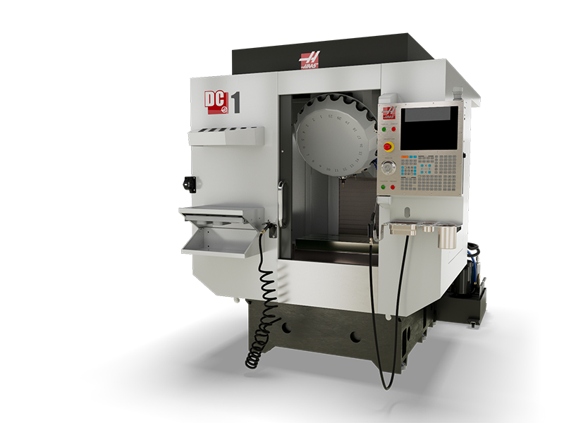
This procedure will guide you through the installation of the DC-1 30-taper and 40-taper machines.

Tools required:

  • Precision Machinist Level, 0.0005" Division
  • 23mm socket and ratchet
  • 40mm wrench
  • 20 mm socket
  • Tape Measure
  • 0.0005" or 1 micron indicator 

The DC-1 can be lifted by forklift, or by using the lifting points on the base and column castings. For details on how to lift the DC-1 refer to the Pre-Installation Guide, or the machine lifting placard located on the machine.

Remove Rust Inhibitor

To safely and effectively remove rust inhibitor from way covers and other non-painted surfaces:

Initial Scraping

  • Use a plastic scraper to remove the bulk of the rust inhibitor.
  • Avoid using metal tools to prevent scratching or damaging the surface.

 Important: Do not use scotch-brite or metal scrapers, these will scratch the way covers.

Chemical Cleaning

  • Spray the affected areas with a heavy-duty citrus cleaner or Simple Green.
  • Ensure full coverage of all non-painted surfaces coated with rust inhibitor.

 Note: If there is rust inhibitor left over that is difficult to remove with simple green, use brake cleaner.

Air Connection

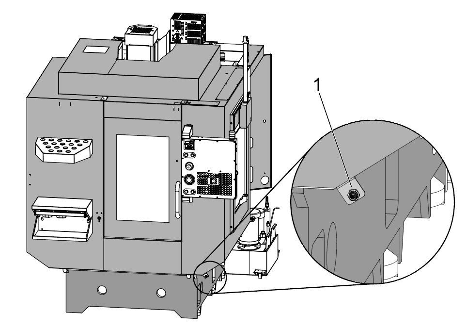
1

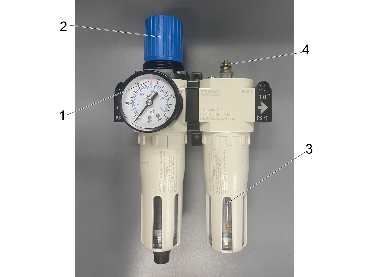
Connect the Air Supply at the lube panel shown in the image as Input Air Supply.

Note: For air specifications refer to the decal located on the front of the lube cabinet door.

The required air pressure for the DC-1 machine is 85psi.

Connect the air supply and verify the pressure gauge [1] on the regulator shows the correct pressure.

If the pressure needs to be adjusted, pull the regulator cap [2] up, and then twist it to set the outgoing air to 85 psi.

Once the gauge reads 85 psi, push the regulator cap down to lock it in place.

Electrical Installation

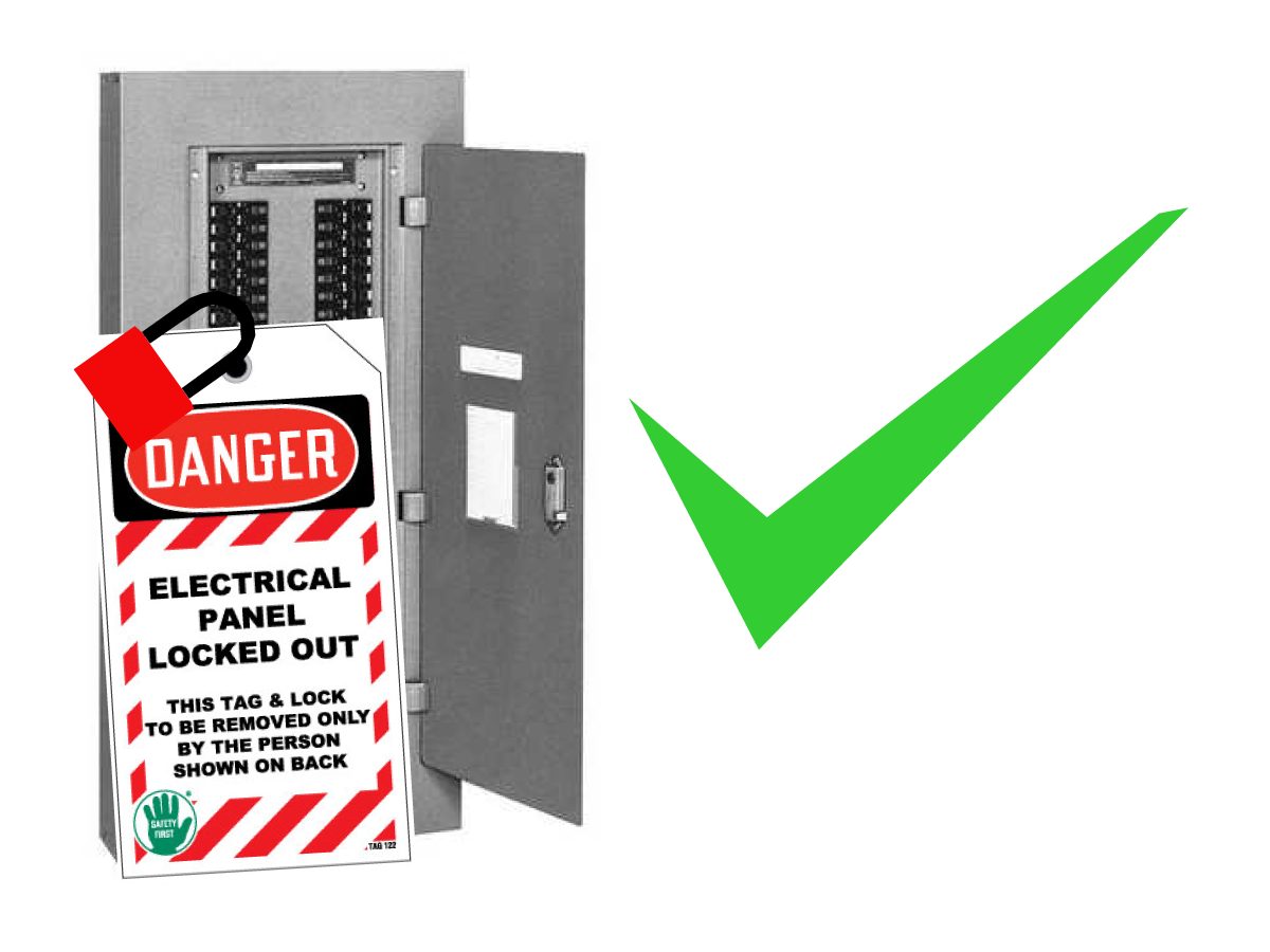
 DANGER: Working with the electrical services required for CNC machines is extremely hazardous and can result in serious injury or death.

Before connecting line wires to the CNC:

  • Turn off all power to the machine at the source.
  • Perform a Lockout-Tagout (LOTO) procedure to ensure the power remains off during service.
  • Verify that power has been disconnected by using an AC voltage detector on all incoming lines.

If you are uncertain about how to safely disconnect power or perform LOTO procedures:

  • Do not proceed.
  • Contact qualified personnel or obtain appropriate assistance before continuing.

Failure to follow these precautions may result in electrical shock, equipment damage, or fatal injury.

1

Initial Control Inspection

Danger: At this point, there should be no electrical connection to the machine. Electrical panel must be closed and secured. When main switch is on, there is HIGH VOLTAGE throughout the electrical panel (including the circuit boards and logic circuits) and some components operate at high temperatures. Therefore, exercise extreme caution when working in the panel.

  • Set the main breaker switch at the upper right of the electrical panel on the back of the machine to OFF.
  • Using a screwdriver, unlock the two latches on the panel door, unlock the cabinet with the key and open the door.
  • Take sufficient time to check all the components and connectors associated with the circuit boards. Look for any cables that have become disconnected, look for any signs damage and loose parts in the bottom of the panel box. If there are any signs that the machine was mishandled, call the factory before proceeding.

2

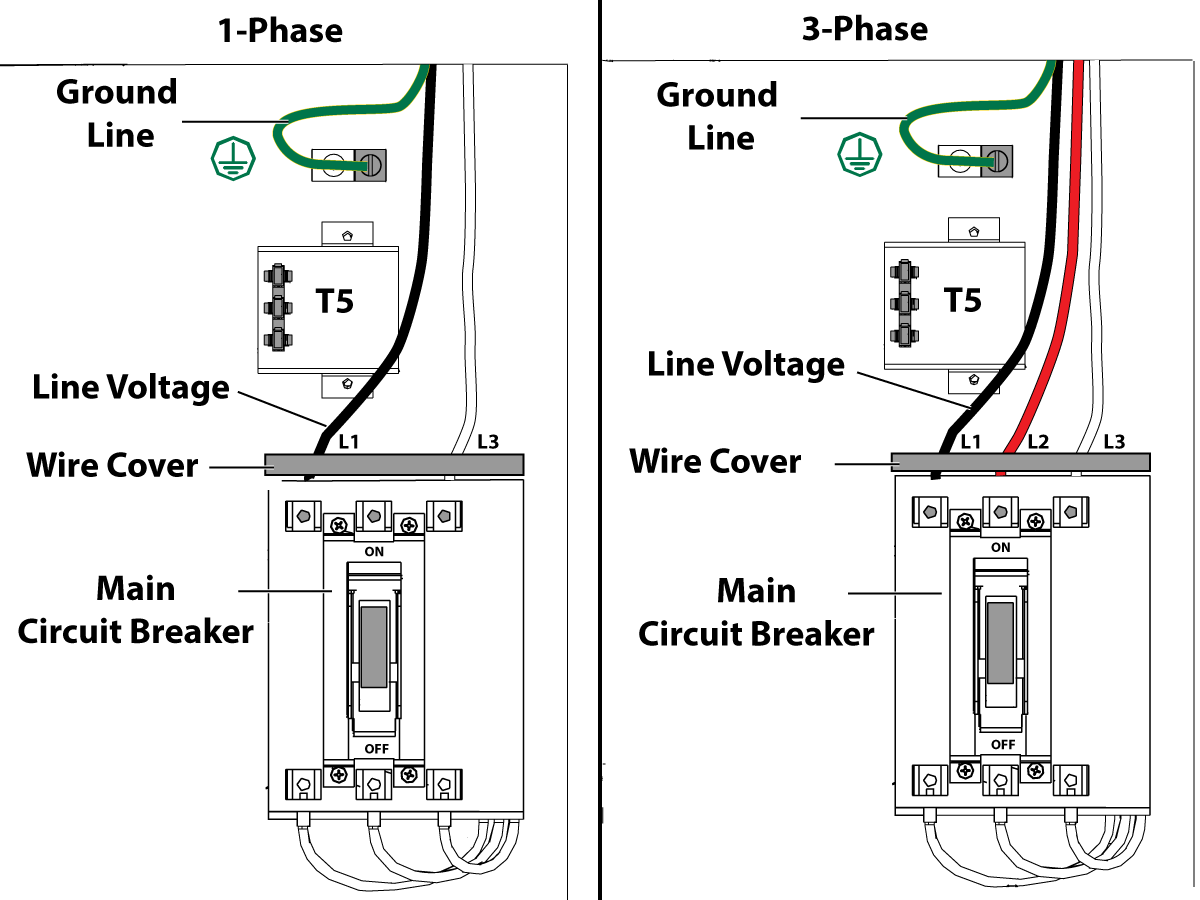
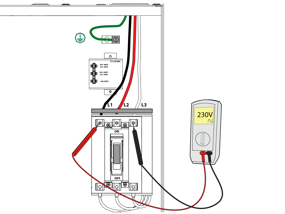
1-Phase Machines: Insert each power lead into the wire cover.  Connect the two power leads to L1 and L3 terminals on top of the main circuit breaker.

3-Phase Machines: Insert each power lead into the wire cover.  Connect the three power leads to L1, L2 and L3 terminals on top of the main circuit breaker.

Connect the separate ground line to the ground bus to the left of the terminals.

For 3-phase machines, check to see what type of power configuration is supplying the machine. Take voltage measurements of each power lead to ground line. Then refer to RD0084 - Input Power Configurations to determine which power lead should be connected to the L1 terminal based of the voltage readings and power configuration.

Refer to Haas Main Circuit Breaker - Torque Specifications for what value to torque the circuit breaker power leads.

 Note: Make sure that the leads actually go into the terminal-block clamps . (A poor connection will cause the machine to run intermittently or have other problems, such as servo overloads.) To check, simply pull on the wires after the screws are tightened.

3

After the line voltage is connected to the machine, make sure that main circuit breaker (at top-right of rear cabinet) is OFF . Remove the Lockout / Tagout and Turn ON the power at the source. Using a digital voltmeter and appropriate safety procedures: 

1-Phase Machines: Measure the AC voltage across L1 & L3 at the main circuit breaker.  The AC voltage must be between 220 - 250 volts .
Note: Lower or higher than this voltage can generate low/high voltage alarms.

3-Phase Machines : Measure the AC voltage between all three pair phases at the main circuit breaker. 

The AC voltage must be between 195 and 260 volts (360 and 480 volts for high voltage option).

SMinimill - Reboot: The AC voltage must be between 198 and 242 volts for machines without a high voltage transformer.  Refer to the Minimill/SMinimill - Identification document.

 Note: Wide voltage fluctuations are common in many industrial areas; minimum and maximum voltage supplied to a machine while it is in operation must be known. U.S. National Electrical Code specifies that machines should operate with a variation of +5% to -5% around an average supply voltage. If problems with line voltage occur, or low line voltage is suspected, an external transformer may be used. If you suspect voltage problems, voltage should be checked every hour or two during a typical day to be sure it does not fluctuate more than +5% or -5% from an average.

4

Important: With the main circuit breaker turned OFF.

Check the transformer taps at the bottom-right corner of the rear cabinet.

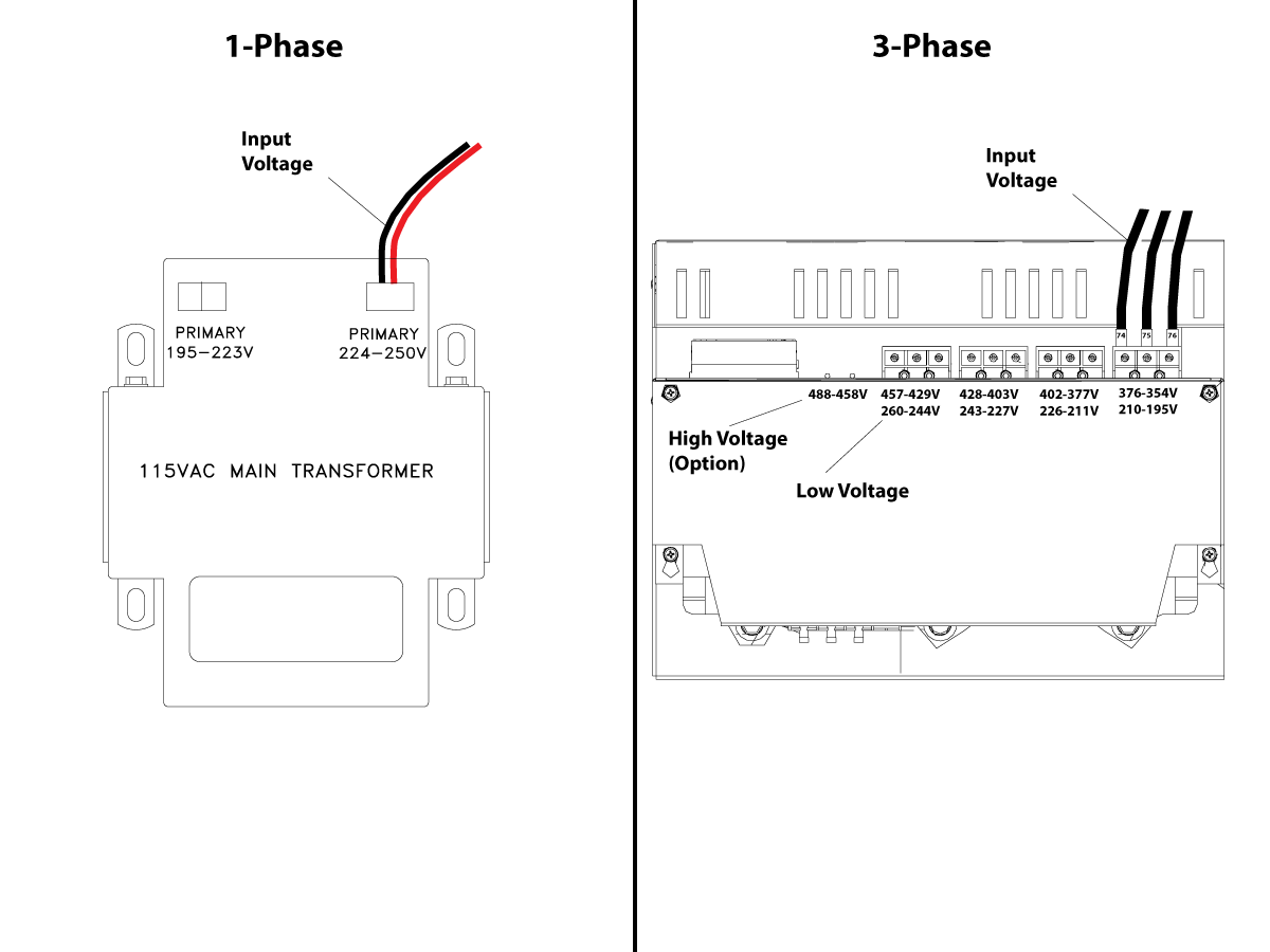
1-Phase Machines: The input voltage cable must be moved to the connector which corresponds to the average voltage measured in the above step.

3-Phase Machines:  The input voltage cables labeled 74, 75, and 76 must be moved to the terminal block triple which corresponds to the average voltage measured in the above step.

5

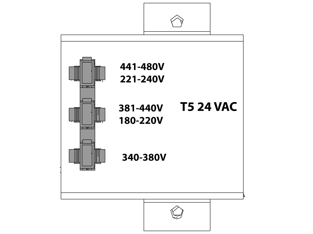
Transformer T5 supplies 24VAC used to power the main contactor. There are two versions of this transformer for use on a 240 and 400V machines. The 240V transformer has two input connectors located about two inches from the transformer, which allow it to be connected to either 180-220V or 221-240V.

Users that have 220V-240V RMS input power should use the connector labeled 221-240V, while users with 190-220V input power should use the connector labeled 180-220V. Failure to use the correct input connector will result in either overheating of the main contactor or failure to reliably engage the main contactor.

The 480V (option) T5 transformer has three input connectors, labeled 340-380V, 381-440V and 441-480V.

Users with 340-380V 50/60Hz power should use the 340-380V connector while users with 380V-440V 50/60Hz power should use the 381-440V connector.

Important: Set the main circuit breaker to ON. Check for evidence of problems, such as the smell of overheating components or smoke. If such problems are indicated, immediately set the main circuit breaker to OFF and call the factory before proceeding.

After the power is on, measure the voltage across the bottom terminals on the main circuit breaker. It should be the same as the measurements where the input power connects to the main breaker. If there are any problems, check the wiring.

6

Apply power to the control by pressing the Power-On switch on the front panel.

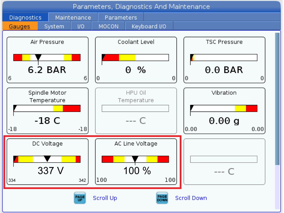
Check the DC Voltage and AC Line Voltage gauges in Diagnostics. The DC Voltage gauge must read between 310 - 360V. The AC Line Voltage must be between 90 and 105 percent. If the voltage is outside these limits, turn off the power and recheck steps 2 and 3. If the voltage is still outside these limits, call the factory.

7

Electrical power must be phased properly to avoid damage to your equipment. The Power Supply Assembly PC board incorporates a "Phase Detect" circuit with neon indicators. When the orange neon is lit (NE5), the phasing is incorrect. If the green neon is lit (NE6), the phasing is correct. If both neon indicators are lit, you have a loose wire; check the connections. Adjust phasing by setting the source power to off and then swapping L1 and L2 of the incoming power lines at the main circuit breaker.

Danger: ALL POWER TO CNC MUST BE TURNED OFF LOCKOUT-TAGOUT AT THE SOURCE PRIOR TO ADJUSTING PHASING. ALWAYS DOUBLE CHECK THE INCOMING LINES WITH AN AC VOLTAGE DETECTOR.

Turn off the power and set the main circuit breaker to OFF. Close the door, lock the latches, and turn the power back on.

Remove the key from the control cabinet and give it to the shop manager.

8

Activation

When the machine is properly placed and connected to both air and electrical power, it is ready for final installation (removing shipping blocks, leveling, spindle sweep, etc.) and software activation. The HFO service technician does this. Contact the local HFO to schedule the work.

IMPORTANT:  Machines equipped with motion sensors must be rough‑leveled before attempting to arm the motion sensor.  For detailed instructions, refer to Service Notification - SA0007.  Access to this document is restricted to Haas Factory Outlet personnel.

Pendant Installation - DC-Series

1

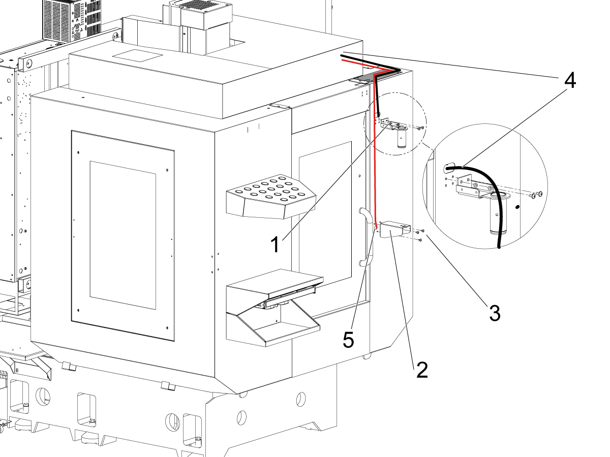
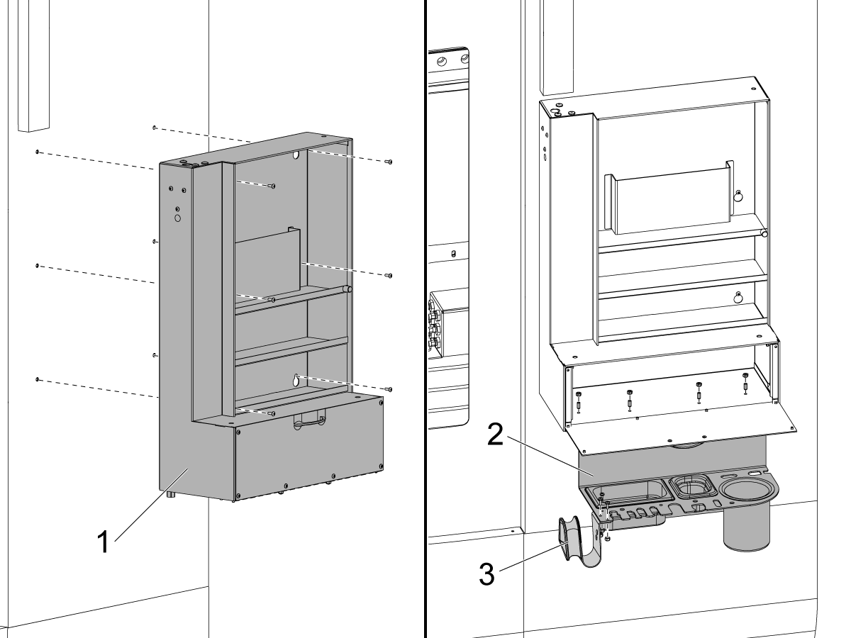
Fasten the top bracket [1] and the bottom bracket [2] that secure the pendant to the enclosure panel [3].

Use 2 BHCS to secure the top bracket, and 3 BHCS to secure the bottom bracket. 

Feed the cables [4] coming from the top of the enclosure through the top bracket so that they can be connected to the pendant.

Note: Make sure the hose for the operator blow gun [5] is fed through the bottom bracket [3]. See next step for connecting blow gun fittings to the bracket

Note: Do not damage the cables when fastening the top bracket. Feed the cables through before fastening the bracket if needed.

2

Install the top bracket cover [1] using the 4 BHCS [2] to fasten the cover to the top bracket that is attached to the pendant.

Secure the bottom of the pendant to the mounting bracket by fastening it with a SHCS [3] from underneath the bracket.

Make sure the rubber spacer [4] is in between the pendant and the mounting bracket. Place the one washer on each side of the rubber spacer.

Note: Make sure the top bracket cover doesn't pinch any of the cables that go to the SKBIF PCB.

3

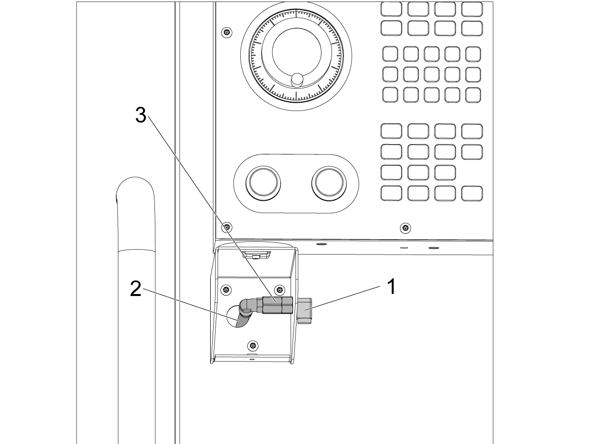
Install the fittings at the bottom mounting bracket for the operator blow gun.

Attach the air hose [2] coming from inside the enclosure (routed in step 1) to the check valve [3].

Fasten the elbow fitting [1] to the check valve with the mounting bracket in between to secure the fittings in place.

Install the cover to the lower bracket to protect the fittings.

Attach the operator blow gun to the elbow fitting [1].

4

Remove the rear panel of the pendant to gain access to the SKBIF PCB.

Make sure to connect all the cables that were routed through the top pendant mounting bracket that was installed in the previous step.

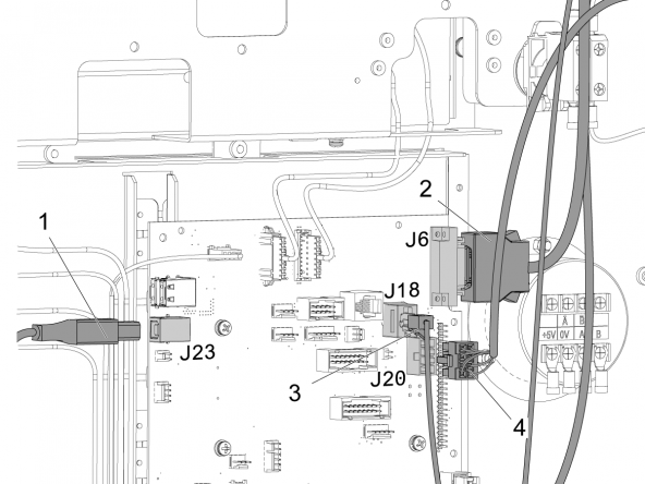
  • Connect 33-4521 to the connector of 33-1300 which is connected to J20 [1] on the SKBIF PCB.
  • Connect the USB cable to J9 [2] of the SKBIF PCB.
  • Connect the ethernet cable to J28 [3] on the SKBIF PCB.
  • Connect the USB from the touchscreen assembly to J11 [4] on the SKBIF PCB. 
  • Connect the ground wire to the cable clamp fastener [5] as shown in the image.

Note: Make sure that the ferrite filters [6] are installed onto the USB cables to protect them from electrical noise.

Once the wiring has been verified, reinstall the rear panel of the pendant.

Auto Window Installation

1

For machines with the auto window feature, the auto window needs to be assembled and installed on the right side window of the machine. 

Important: The machine will be in an alarm state until the auto window cable 33-1169 is connected to P13 on the IO board and the clamp sensors are properly installed. Continue with these steps and AD0652 for instructions on installing the auto window.

The auto window kit is contained in the 30-14126 package that is shipped with the machine.

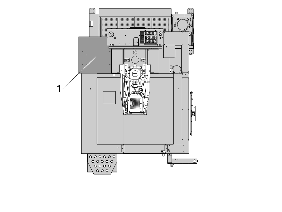
Remove the right window enclosure panel [1] from the DC-1 by unfastening the 4 BHCS [2]. 

2

Remove the jumper wire (33-1388) [1] from the window close connector of the (33-1169) cable [2]. The 33-1169 cable is connected to P13 of the IO PCB. 

This jumper wire [1] gets replaced by the connector to the window closed sensor [3]. This sensor is on the bottom of the cylinder behind the enclosure cover.

Note: The purpose of this jumper is to prevent alarms related to the window being open prior to the auto window being installed.

Once this jumper is removed, the haas control will throw an alarm saying that the side window is not closed.

To clear this alarm, the clamp sensor [3] must be installed onto the auto window lift cylinder.

Refer to AD0652 for instructions on how to install the cylinder and sensors.

3

Slide the two window guides [1] onto the side window enclosure panel [2].

To secure the window guides in place, bend the tabs [3] extending from the top of the enclosure panel over the window guides to lock them in position.

Slide the window [4] from the top into the guides [1] and test that the window slides through the guides easily and can be aligned with the window lift bracket [5]. 

Important: Do not fix the lift bracket [5] to the window at this time. AD0652 provides details on how to complete the auto window installation.

4

Take the auto window mounting panels [1] and fasten them to the DC-1 enclosure [3] as shown in the left image.

Fasten the window panel [4] to the mounting panels [1] using the 6 FBHCS [5] fasteners included in the kit.

Note: The right image shows the window panel mounting from the viewpoint of inside the machine. Make sure the mounting panels [1] are facing the proper direction.

5

The lift cylinder assembly for the DC-1 auto window is the same as other auto windows for other machines. 

6

Note: Refer to AD0652 - Auto Window Installation for details on installing the window, clamp sensors, and cylinder alignment. AD0652 contains instructions on how to complete the auto window installation and testing for the DC-1 machine. 

Shipping Brackets Removal

1

Remove the bolt keeping the door fastened to the enclosure [2].


2

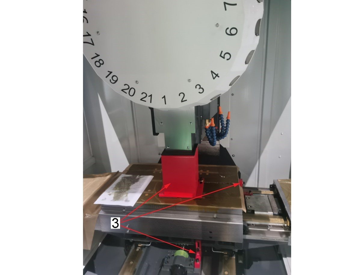
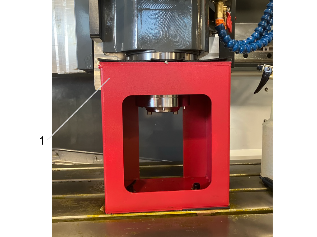
Remove the X-axis and Y-axis shipping brackets. Power on the machine and jog the Z-axis up so that you can remove the spindle head bracket [3] from the table.

Note: If the Z-axis cannot be jogged up far enough, the Z-axis zero position isn't set correctly. Refer to Chapter 5 - Operation / Tool Changer for details on how to reset the Z-axis zero position. 

3

Once the X-axis and Y-axis shipping brackets have been removed, the waycovers need to be fastened in position.

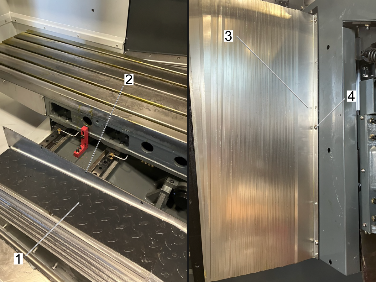
Remove the front table cover [1] and make sure that all waycover fasteners [2] are removed from the front cover and back side of the table.

Note: Before jogging along any axis of the machine, make sure the fasteners for the waycovers are removed. 

Once the front cover is removed, use the fasteners removed and the bag of fasteners ziptied to the Y-axis waycover [3].

4

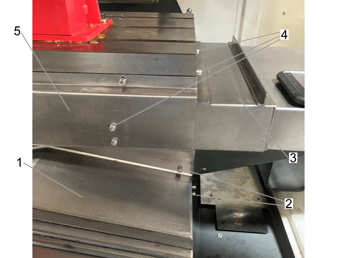
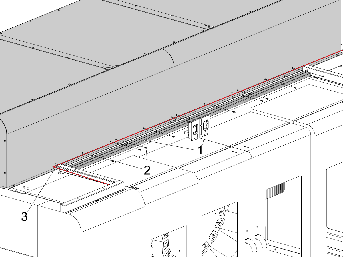
Slide the waycovers into position as shown in the image.

Install the Y-axis waycover [1] to the saddle using the fasteners [2]

Fasten the X-axis waycovers [3] in position using the fasteners [4].

Note: Some of the X-axis waycover fasteners cannot be installed until after the front cover [5] is installed

Apply RTV sealant to the seams where the waycovers join the table to prevent coolant intrusion under the waycovers.

Install the table front cover [5] that was removed in the previous step.

Note: Make sure that the the fasteners on the back side of the table are 

Machine Leveling

1

Zero return each axis one at a time or press [POWER UP]. Go through the leveling process.
Repeat these steps to achieve correct machine level.

2

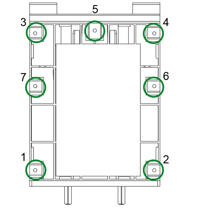
Set the machine height using the four corner leveling bolts [1 ,2, 3, 4] to 3" +/- .5" (75 mm +/- 10 mm) above the floor. Turn each screw so they have equal tension.

Jog the X-axis and Y-axis to the middle of their travel, centering the table.

Note: For more information, refer to this link for a more detailed process on how to level a VMC machine.

VMC Leveling

3

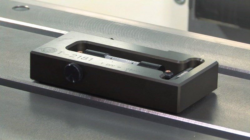
Clean the table surface and leveling tool (T-2181) and check the calibration of the leveling tool before proceeding.

Position the level at the center of the table, parallel to the X-axis. Use a t-slot for alignment.

Note the position of the bubble.

Reposition the level by turning it 180 degrees. The bubble should display the same reading as previously.

If the readings are different by more than one division, return the level to Haas for adjustment and do not use it to level the machine.

4

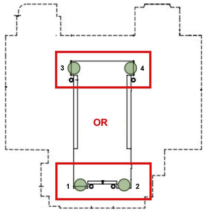
Adjust corner leveling bolts [1, 2] or [3, 4] until the bubble parallel with the Y-axis is centered.

This levels the machine front to back.

Always raise the lower side of the machine to maintain clearance for the coolant tank (if equipped) and adjust the two leveling bolts on that side an equal amount.

5

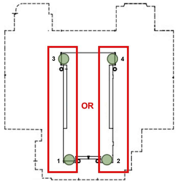
Adjust corner leveling bolts [1, 3] or [2, 4] until the bubble parallel to the X-axis is centered.

This levels the machine left to right.

Again, raise the lower side of the machine and adjust the two leveling bolts on that side an equal amount.

6

Keep the level in the same position and jog the Y-axis to bring the table to the front of the machine.

Note the position of the bubble.

Jog the Y-axis across its full travel, stopping at the column. Look to see which rear corner of the machine is lowest, as shown by the leveling tool.

Raise the lowest rear corner by adjusting corner leveling bolt [3] or [4] until the bubble is centered on the level.

7

Jog the Y-axis back across its full travel, bringing the table to the front of the machine. Look to see which front corner is lowest, as shown by the level.

Raise the lowest front corner by adjusting corner leveling bolt [1] or [2] until the bubble is centered on the level.

Repeat steps 6 and 7, moving the table back and forth across the full travel of the Y-axis, raising the lowest corner each time.

Continue this process until the level reads zero at both ends of the Y-axis travel.

8

Once the machine has been leveled along both the X and Y axes, raise up the non-corner leveling bolts [5, 6, and 7] so that they are making contact with the base to provide support.

Spindle Sweep Check

1

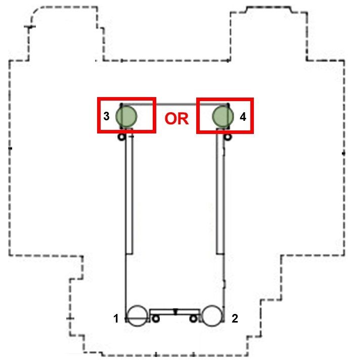
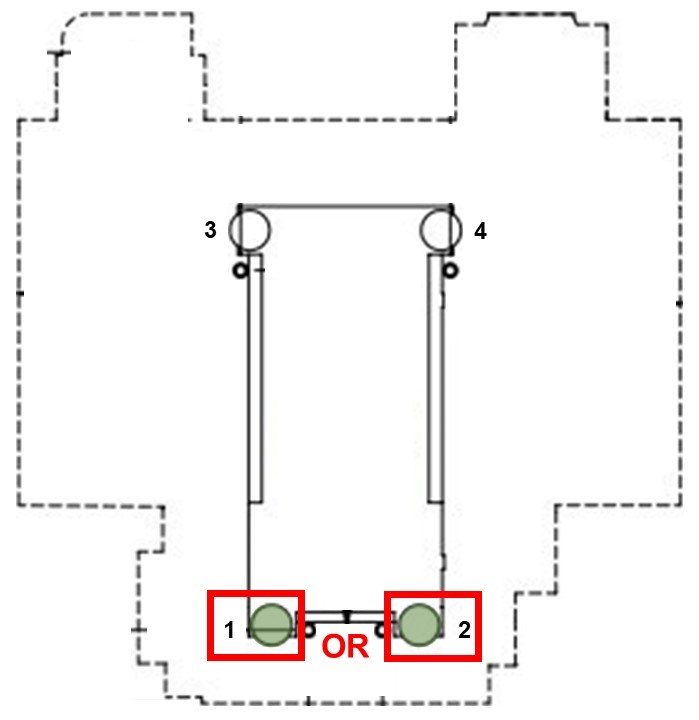
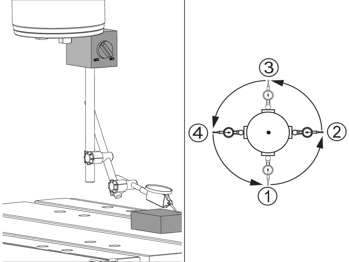
Attach an indicator to spindle head. Position the table and indicator to sweep a circle 10" in diameter.
 
Place a gauge block on the table.
 
Jog the spindle down and zero the indicator at Position 1. 
 
Using a gauge block every 90 degrees, check that the difference in these measurements don't exceed 0.0005". If it does, check the machine level.
 

Lock the leveling bolts in place by tightening the locking nut while holding the leveling bolt. Ensure that the leveling bolts do not move during this process.

For a more in-depth guide on how to perform this procedure, please see:

Spindle Sweep

Spindle Chiller Installation

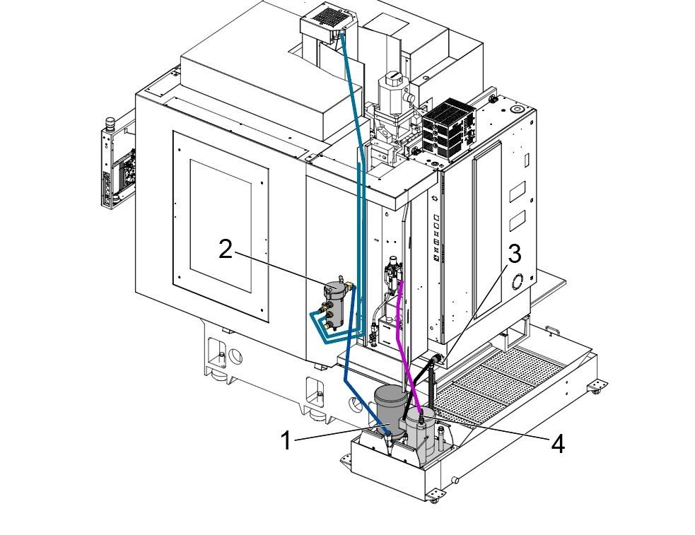
1

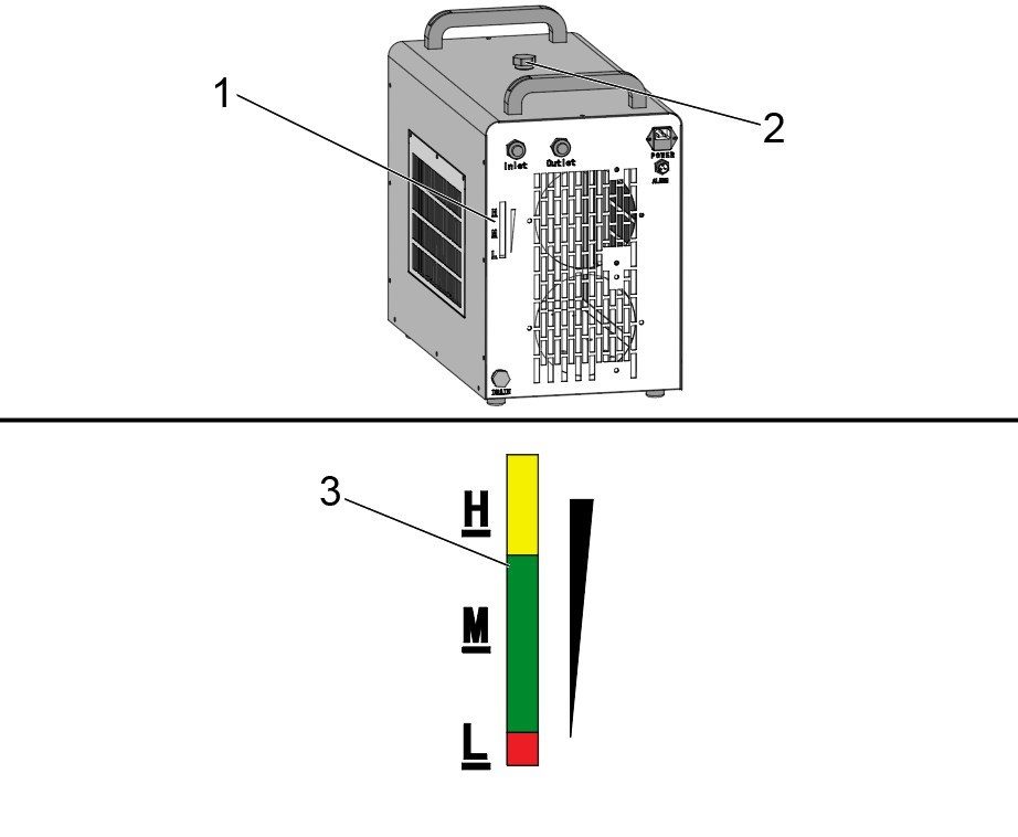
Make sure the spindle chiller is in position on the platform[1] located to the rear of the machine.

There is a power cable, a flow alarm cable, and a ground cable that are installed to the control cabinet at the factory.

Note: Refer to the DC-1 - Spindle Chiller chapter of this manual for more information.

2

Verify that the fluid tank is full by inspecting the fluid level gauge [1] on the back of the spindle chiller unit.

Add fluid if needed through the inlet port at the top of the unit. The fluid gauge should show the level is near the top of the M range [2]. 

Note: Use a mixture of 30% ethylene glycol and 70% dionized water to fill the spindle chiller.

Important: Never run the Spindle Chiller without fluid in the tank. This can cause serious damage to the pump.

3

Make sure that the switch located on the front of the chiller unit is on. The settings and parameters for the chiller are set in the factory and should not be altered.

Note: The display of the spindle chiller will be blank. The chiller powers itself on when the spindle is running or during tool changes. 

Air Lubrication Flow Rate Verification

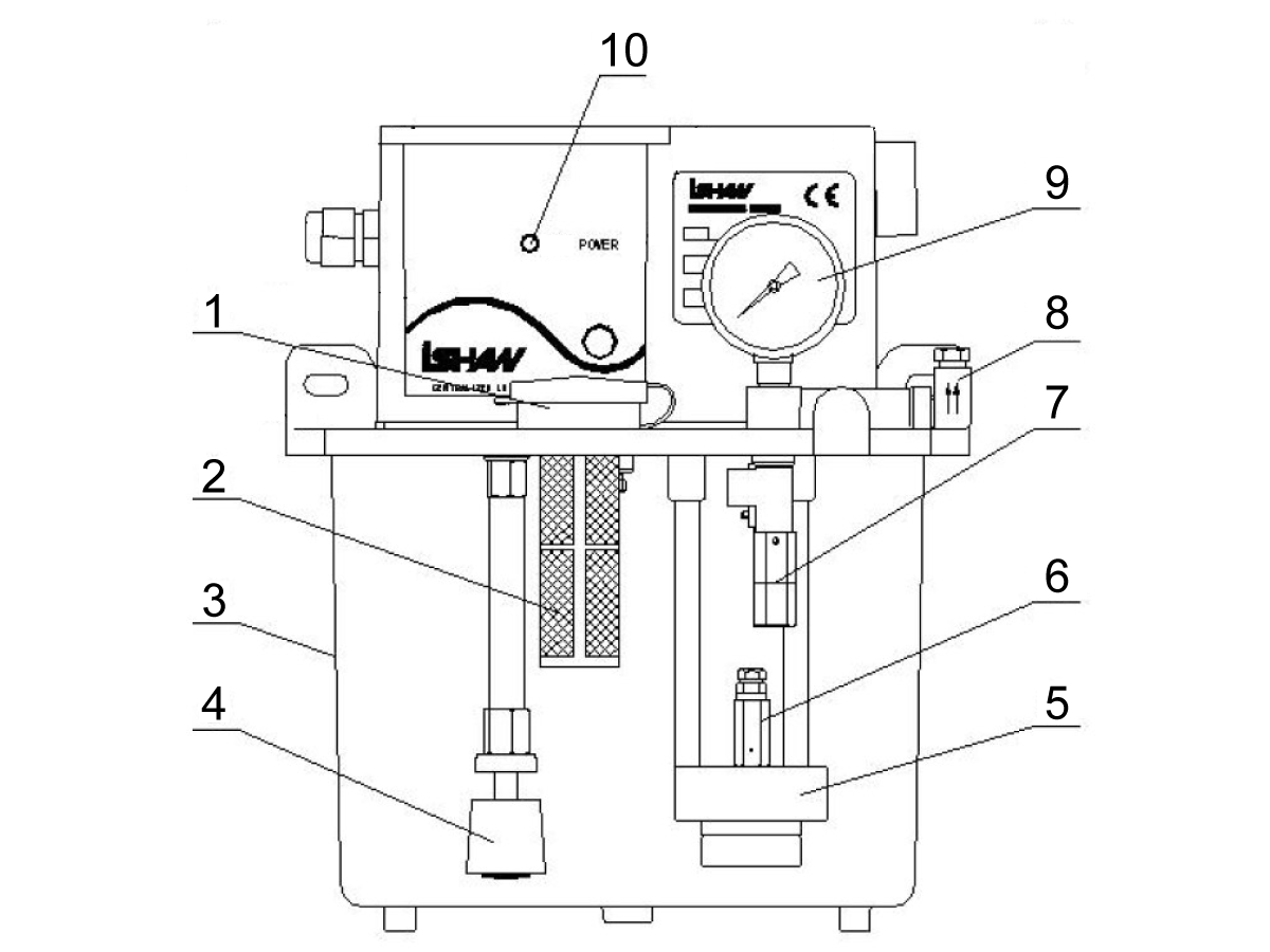
Verify that the oil reservoir [3] is filled with Mobil DTE 24 Ultra (93-2546).

The flow rate of the oil into the air system also needs to be set correctly. Adjust the set screw [4] so that the flow rate is 1 drop every 3 to 10 minutes. The oil drip will be visible through the sight glass below the set screw [4].

The flow rate of oil into the airlines can only be set when the spindle is running. Run the following MDI program when trying to set the flow rate:

  • S50 M99; 

Loosening the set screw will increase the flow rate of oil, and tightening will decrease the flow rate.

Note: Having a flow rate higher than this range could flood the air supply which could damage the machine.


Axis Lubrication Verification

1

Run the spindle run-in program.

Examine the sight glass, make sure the correct number of drops fall through the sight glass. 

Examine the fittings [1,2] on top of the oil pump tank.

The oil collects on top of the oil pump tank [3] either behind or in front of the sight glass bracket, underneath the leaking fitting.

Tighten any leaking fittings.

2

Go to the Maintenance tab.

Press [F2] to cycle an axis lubrication test.

Inspect the gauge on the grease lubrication system. Make sure it holds pressure.

Single/Dual Programmable Air Option

1

Machines with Single/Dual Prog Air Option Only: 

Route the Foot Pedal cable (32-1390) from the control along the enclosure panels to the foot pedal cable mounting bracket[1].

For more details, refer to the Programmable Air Installation procedure.

Coolant Tank Installation

1

Power off the machine.

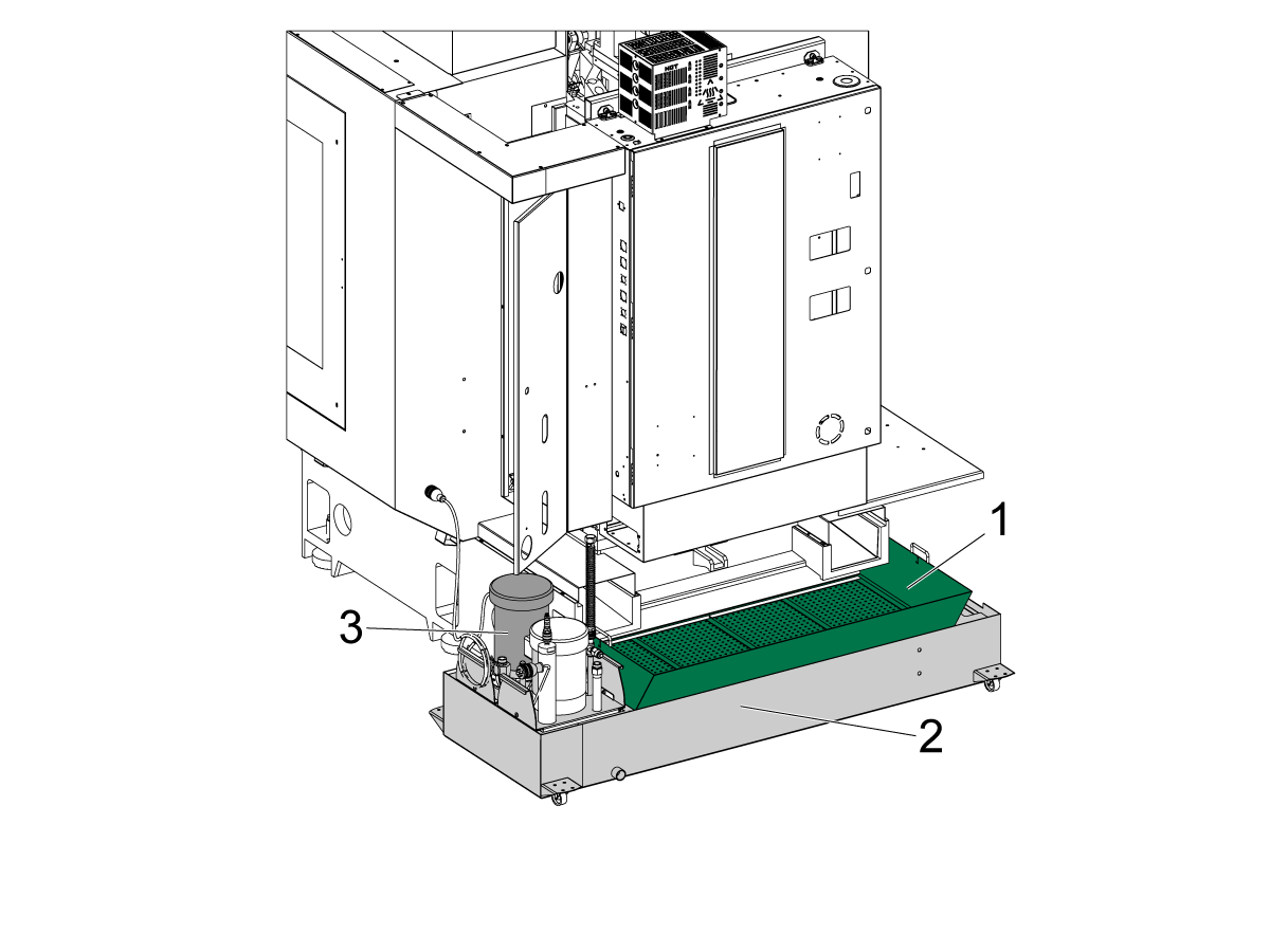
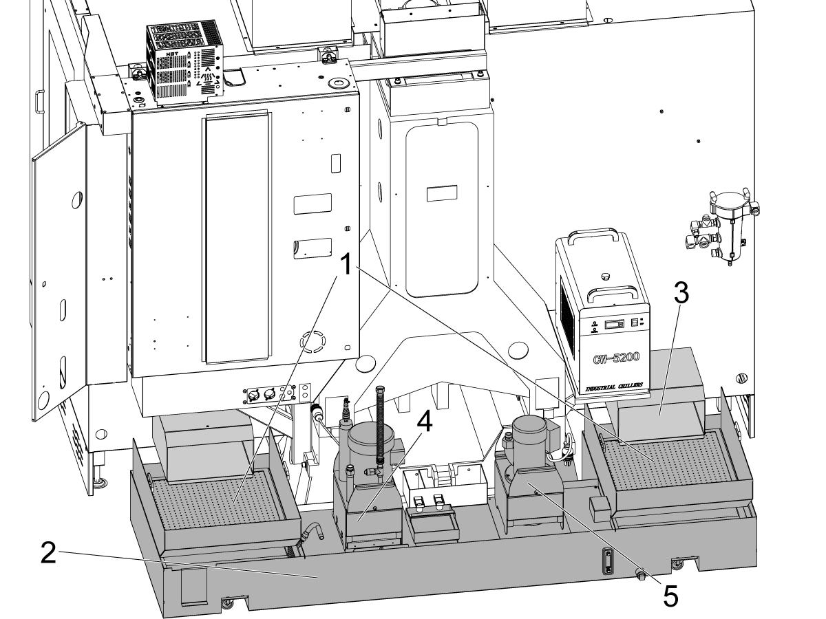
Place the strainer basket [1] into the coolant tank [2].

Move the coolant tank assembly [2] under the drain slots at the base of the mill, under the front-left corner of the trough.

 NOTE: Make sure that the strainer basket [1] is directly under the drain slots to ensure coolant flows into the tank. 

Insert the coolant pump assembly [3] into the back left corner of the coolant tank when facing the spindle. 

2

Connect the hose to the coolant pump [1] into the coolant filter [2].

Connect the coolant pump power cable into the plug located beneath the control cabinet[3]. 

If included as a machine option, route the TSC pump[4] to the lube panel and fill the coolant tank with the necessary gallons of coolant.

Install the coolant float sensor into the coolant tank. Refer to Coolant Float Sensor - NGC - Installation or Coolant Float Sensor - CHC - Installation for more information. 

Option Installation Guides

Verify and test that all the machine options have been properly installed.

Remote Jog Handle XL (RJH-XL) - Installation
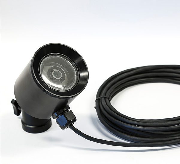
Wi-Fi Camera Installation
Convenience Package
Auxilary Coolant Filter
CABCOOL installation
HPFC Installation
Haas Cobot 10 Installation
Haas Oil Skimmer Installation
Table work light
Tool Air Blast
WIPS Installation
AutoWindow Install
Dual Programmable Air
Programmable Air

Final Testing

1

Spindle Operation 

Run the Spindle Run-In program O09221. 

In the case of an unusual spindle noise, run a vibration test. For a guide on how to perform a spindle vibration test please see: 

Vibration Analysis - Ethernet Interface
Vibration Analysis - RS-232 Interface

2

Coolant and Air Blast-DC Operation

Fill the coolant tank with the necessary gallons of coolant in order to fill the tank.

Connect the coolant pump.

Run coolant by pressing  [COOLANT] on control pendant.

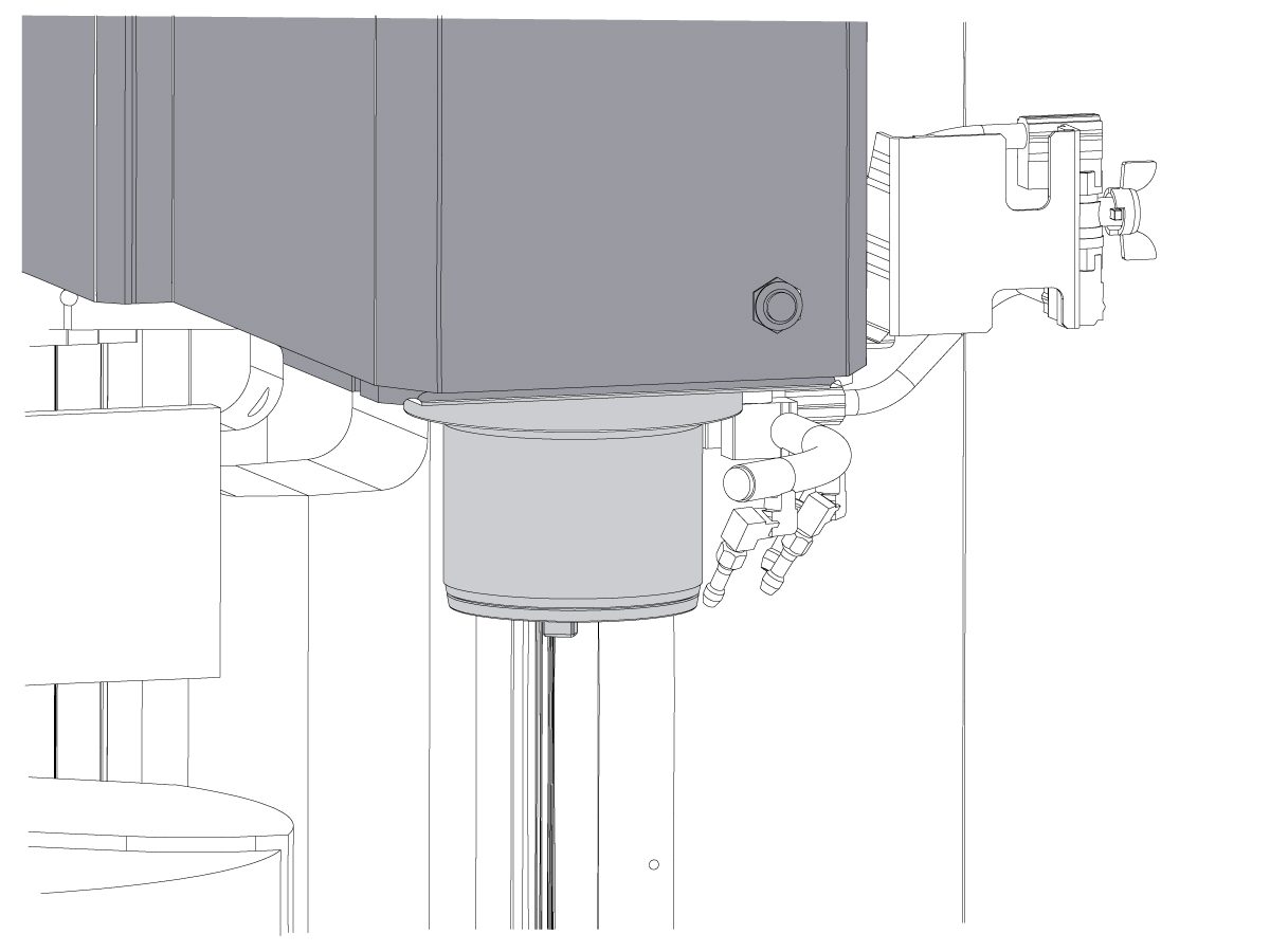
Verify that there is coolant coming out of the nozzles around the machine.

There are two nozzles for coolant located by the spindle head. Make sure coolant comes out of the two nozzles on the left.

Note: The third nozzle by the spindle head is for the Air Blast-DC option. Refer to the decal [1] for which nozzles are for coolant.

To verify that the Air Blast option is operational, run the following command in MDI mode and make sure air comes out of the nozzle labeled AIR BLAST:

  1. M83 - starts the air blast
  2. M84 - stops the air blast

3

Through Spindle Coolant (TSC) 

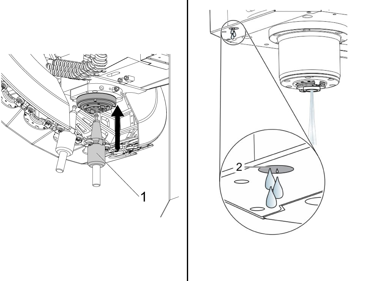
If machine comes equipped with TSC, insert a TSC toolholder into the tool carousel side pocket.

Then load the toolholder into the spindle by calling T[pocket_number] on the control and pressing ATC FWD.

Important: Tools cannot be loaded directly into the spindle on a DC machine. For more details on how to load tools into the spindle for the DC machine, refer to the Operation Chapter.

Press [AUX CLNT] to start the TSC.

Correct operation is as follows:

  1. Coolant flows correctly from the TSC tool holder.
  2. A few drops flow from the vacuum-generator hose [2].

Press [RESET].

4

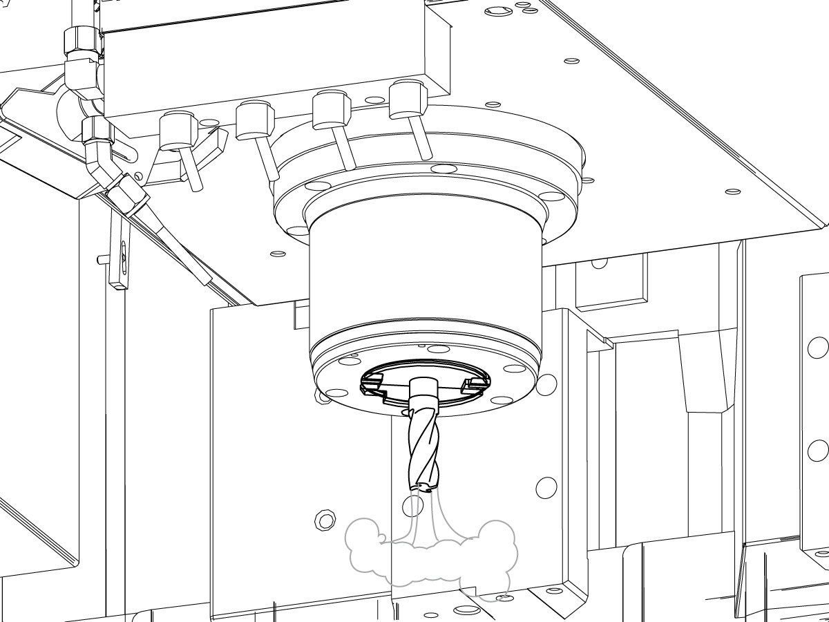
Through-Tool Air Blast (TAB)

If machine comes equipped with TAB, operate this code in MDI mode:

M73;

G04 P5.;

M74;

G04 P3.;

M99;

M73 starts the TAB. M74 stops the TAB.

Manually operate the TAB:

Press [AUX CLNT]. Press the [RIGHT] cursor arrow.

The tool air blast starts.

Press [AUX CLNT].

The tool air blast stops.

5

Door Interlock

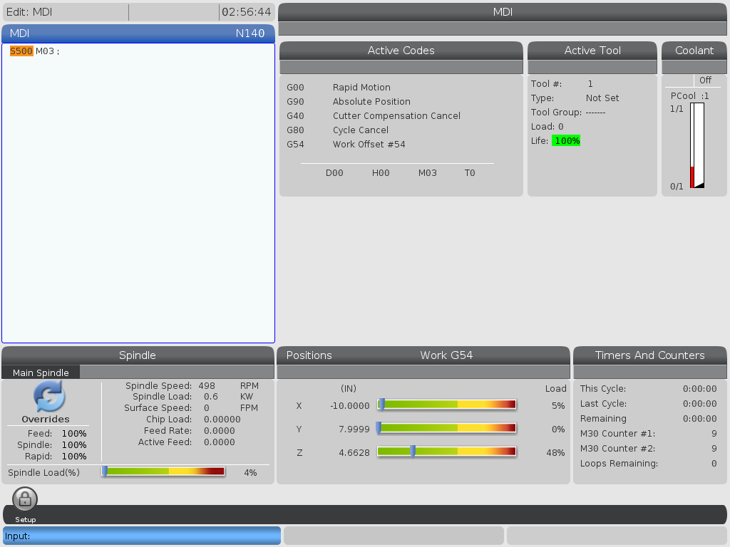
Press [MDI]. Type in S500 M3; Press [ENTER].

Make sure the machine IS NOT in SETUP MODE by checking the KEY SWITCH on the side of the pendant

With the door open, press [CYCLE START]. The machine should say to close the door and press [CYCLE START].

With the door closed, press [CYCLE START]. The interlock pin should extend and the spindle starts rotating.

 IMPORTANT: With the spindle rotating, test the door locks by trying to open the door. The spindle should not stop rotating. 

6

Test Key Switches

Insert the Setup/Run Lock Key (#2007) to the lower key slot and turn to the unlocked position.

Verify that the key can only be removed from the locked position.

Insert the Memory Lock Key (#2341) to the upper key slot and turn to the locked position.

Verify that the key can be removed from either position.

With the Memory Lock Key in the locked position, verify that changes cannot be made to the settings or programs.

7

Auto Window Installation

If machine has the auto window option, refer to Auto Window Installation - AD0652 for information on how to install the auto window on the DC-1.

Assemble the window enclosure.

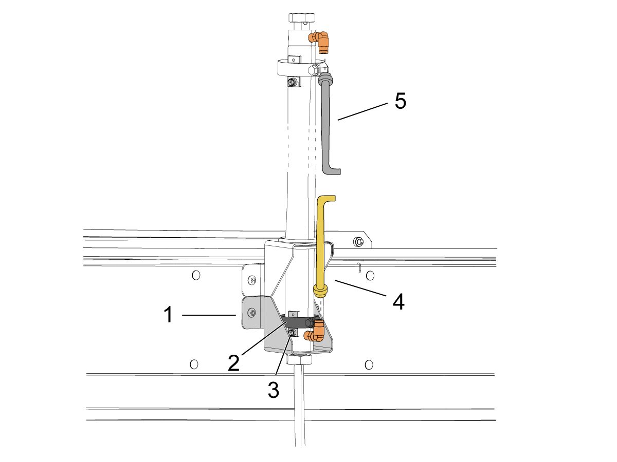
Bolt the bottom bracket [1] to the enclosure above the window. 

Loosen the sensor clamp [2] on the bottom of the air cylinder.  Insert sensor [3] in between clamp and piston rod. Before tightening the sensor clamp, refer to the Auto Window - Troubleshooting Guide for sensor location. 

Remove the fitting plugs on the top and bottom of the air cylinder.  Connect the yellow airline [4] to the bottom hose fitting and the grey airline [5] to the top hose fitting. 

Reinstall enclosure cover. 

To test the auto window, operate this code in MDI mode:

M59 P151;

G04 P5.;

M69 P151;

G04 P5.;

M99;

8

Rotary Installation

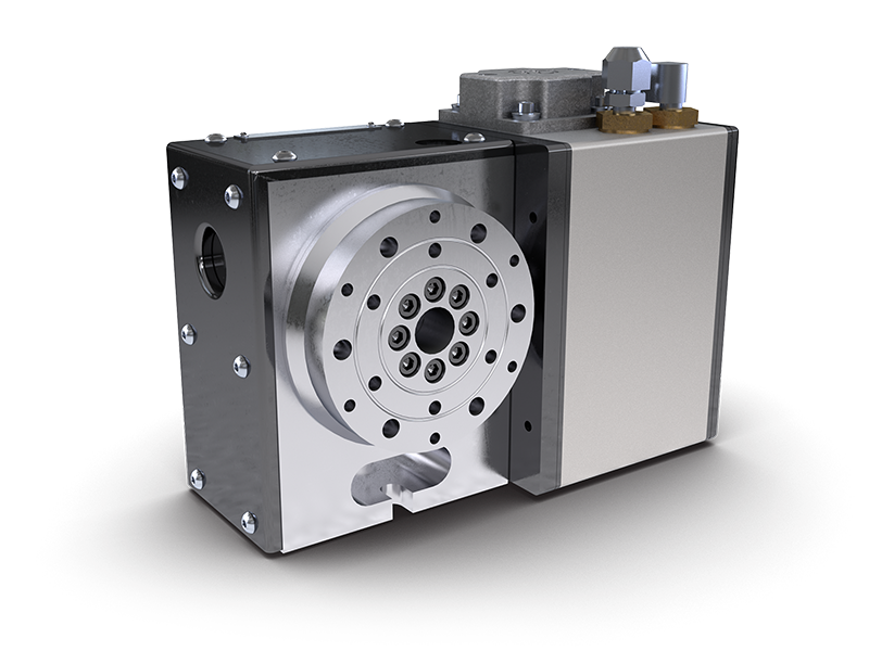
If your machine came with a HRT or TRT rotary table please see the following link for installation instructions:

Rotary Installation

9

WIPS Calibration 

If your machine includes the WIPS option, please see the following link for instructions on the calibration procedure:

WIPS Calibration NGC

10

Wifi Camera Operation 

If the machine came with the Wifi Camera option, please see the following link for installation instructions:

Wi-fi Camera Installation

DC-1 Maintenance Schedule

Keep your Haas machines running at peak performance while avoiding unplanned downtime. A maintenance program allows you to manage your schedule rather than getting caught with untimely surprises. Please see the link below for recommended maintenance intervals for this machine.


DC-1 MAINTENANCE

4.2 DC-2 - Installation

Recently Updated

DC-2 Installation


Revision A - 05/2025

Introduction

This procedure will guide you through the installation of the DC-2 30-taper and 40-taper machines.

Tools required:

  • Precision Machinist Level, 0.0005" Division
  • 23mm socket and ratchet
  • 40mm wrench
  • 20 mm socket
  • Tape Measure
  • 0.0005" or 1 micron indicator 

The DC-2 can be lifted by forklift, or by using the lifting points on the base and column castings. For details on how to lift the DC-2 refer to the Pre-Installation Guide, or the machine lifting placard [1] located on the machine.

The DC-2 machine weighs 8860 lbs (4020 kg). Check the specification of the lifting equipment before trying to lift.

 Important: The DC-2 machine is required to be anchored. See section 4.5 Anchoring for the anchoring kit part number and instructions.

Remove Rust Inhibitor

To safely and effectively remove rust inhibitor from way covers and other non-painted surfaces:

Initial Scraping

  • Use a plastic scraper to remove the bulk of the rust inhibitor.
  • Avoid using metal tools to prevent scratching or damaging the surface.

 Important: Do not use scotch-brite or metal scrapers, these will scratch the way covers.

Chemical Cleaning

  • Spray the affected areas with a heavy-duty citrus cleaner or Simple Green.
  • Ensure full coverage of all non-painted surfaces coated with rust inhibitor.

 Note: If there is rust inhibitor left over that is difficult to remove with simple green, use brake cleaner.

Air Connection

1

Connect the Air Supply at the lube panel shown in the image as Input Air Supply.

Note: For air specifications refer to the decal located on the front of the lube cabinet door.

The required air pressure for the DC-2 machine is 85psi.

Connect the air supply and verify the pressure gauge [1] on the regulator shows the correct pressure.

If the pressure needs to be adjusted, pull the regulator cap [2] up, and then twist it to set the outgoing air to 85 psi.

Once the gauge reads 85 psi, push the regulator cap down to lock it in place.

Electrical Installation

 DANGER: Working with the electrical services required for CNC machines is extremely hazardous and can result in serious injury or death.

Before connecting line wires to the CNC:

  • Turn off all power to the machine at the source.
  • Perform a Lockout-Tagout (LOTO) procedure to ensure the power remains off during service.
  • Verify that power has been disconnected by using an AC voltage detector on all incoming lines.

If you are uncertain about how to safely disconnect power or perform LOTO procedures:

  • Do not proceed.
  • Contact qualified personnel or obtain appropriate assistance before continuing.

Failure to follow these precautions may result in electrical shock, equipment damage, or fatal injury.

1

Initial Control Inspection

Danger: At this point, there should be no electrical connection to the machine. Electrical panel must be closed and secured. When main switch is on, there is HIGH VOLTAGE throughout the electrical panel (including the circuit boards and logic circuits) and some components operate at high temperatures. Therefore, exercise extreme caution when working in the panel.

  • Set the main breaker switch at the upper right of the electrical panel on the back of the machine to OFF.
  • Using a screwdriver, unlock the two latches on the panel door, unlock the cabinet with the key and open the door.
  • Take sufficient time to check all the components and connectors associated with the circuit boards. Look for any cables that have become disconnected, look for any signs damage and loose parts in the bottom of the panel box. If there are any signs that the machine was mishandled, call the factory before proceeding.

2

1-Phase Machines: Insert each power lead into the wire cover.  Connect the two power leads to L1 and L3 terminals on top of the main circuit breaker.

3-Phase Machines: Insert each power lead into the wire cover.  Connect the three power leads to L1, L2 and L3 terminals on top of the main circuit breaker.

Connect the separate ground line to the ground bus to the left of the terminals.

For 3-phase machines, check to see what type of power configuration is supplying the machine. Take voltage measurements of each power lead to ground line. Then refer to RD0084 - Input Power Configurations to determine which power lead should be connected to the L1 terminal based of the voltage readings and power configuration.

Refer to Haas Main Circuit Breaker - Torque Specifications for what value to torque the circuit breaker power leads.

 Note: Make sure that the leads actually go into the terminal-block clamps . (A poor connection will cause the machine to run intermittently or have other problems, such as servo overloads.) To check, simply pull on the wires after the screws are tightened.

3

After the line voltage is connected to the machine, make sure that main circuit breaker (at top-right of rear cabinet) is OFF . Remove the Lockout / Tagout and Turn ON the power at the source. Using a digital voltmeter and appropriate safety procedures: 

1-Phase Machines: Measure the AC voltage across L1 & L3 at the main circuit breaker.  The AC voltage must be between 220 - 250 volts .
Note: Lower or higher than this voltage can generate low/high voltage alarms.

3-Phase Machines : Measure the AC voltage between all three pair phases at the main circuit breaker. 

The AC voltage must be between 195 and 260 volts (360 and 480 volts for high voltage option).

SMinimill - Reboot: The AC voltage must be between 198 and 242 volts for machines without a high voltage transformer.  Refer to the Minimill/SMinimill - Identification document.

 Note: Wide voltage fluctuations are common in many industrial areas; minimum and maximum voltage supplied to a machine while it is in operation must be known. U.S. National Electrical Code specifies that machines should operate with a variation of +5% to -5% around an average supply voltage. If problems with line voltage occur, or low line voltage is suspected, an external transformer may be used. If you suspect voltage problems, voltage should be checked every hour or two during a typical day to be sure it does not fluctuate more than +5% or -5% from an average.

4

Important: With the main circuit breaker turned OFF.

Check the transformer taps at the bottom-right corner of the rear cabinet.

1-Phase Machines: The input voltage cable must be moved to the connector which corresponds to the average voltage measured in the above step.

3-Phase Machines:  The input voltage cables labeled 74, 75, and 76 must be moved to the terminal block triple which corresponds to the average voltage measured in the above step.

5

Transformer T5 supplies 24VAC used to power the main contactor. There are two versions of this transformer for use on a 240 and 400V machines. The 240V transformer has two input connectors located about two inches from the transformer, which allow it to be connected to either 180-220V or 221-240V.

Users that have 220V-240V RMS input power should use the connector labeled 221-240V, while users with 190-220V input power should use the connector labeled 180-220V. Failure to use the correct input connector will result in either overheating of the main contactor or failure to reliably engage the main contactor.

The 480V (option) T5 transformer has three input connectors, labeled 340-380V, 381-440V and 441-480V.

Users with 340-380V 50/60Hz power should use the 340-380V connector while users with 380V-440V 50/60Hz power should use the 381-440V connector.

Important: Set the main circuit breaker to ON. Check for evidence of problems, such as the smell of overheating components or smoke. If such problems are indicated, immediately set the main circuit breaker to OFF and call the factory before proceeding.

After the power is on, measure the voltage across the bottom terminals on the main circuit breaker. It should be the same as the measurements where the input power connects to the main breaker. If there are any problems, check the wiring.

6

Apply power to the control by pressing the Power-On switch on the front panel.

Check the DC Voltage and AC Line Voltage gauges in Diagnostics. The DC Voltage gauge must read between 310 - 360V. The AC Line Voltage must be between 90 and 105 percent. If the voltage is outside these limits, turn off the power and recheck steps 2 and 3. If the voltage is still outside these limits, call the factory.

7

Electrical power must be phased properly to avoid damage to your equipment. The Power Supply Assembly PC board incorporates a "Phase Detect" circuit with neon indicators. When the orange neon is lit (NE5), the phasing is incorrect. If the green neon is lit (NE6), the phasing is correct. If both neon indicators are lit, you have a loose wire; check the connections. Adjust phasing by setting the source power to off and then swapping L1 and L2 of the incoming power lines at the main circuit breaker.

Danger: ALL POWER TO CNC MUST BE TURNED OFF LOCKOUT-TAGOUT AT THE SOURCE PRIOR TO ADJUSTING PHASING. ALWAYS DOUBLE CHECK THE INCOMING LINES WITH AN AC VOLTAGE DETECTOR.

Turn off the power and set the main circuit breaker to OFF. Close the door, lock the latches, and turn the power back on.

Remove the key from the control cabinet and give it to the shop manager.

8

Activation

When the machine is properly placed and connected to both air and electrical power, it is ready for final installation (removing shipping blocks, leveling, spindle sweep, etc.) and software activation. The HFO service technician does this. Contact the local HFO to schedule the work.

IMPORTANT:  Machines equipped with motion sensors must be rough‑leveled before attempting to arm the motion sensor.  For detailed instructions, refer to Service Notification - SA0007.  Access to this document is restricted to Haas Factory Outlet personnel.

Control Regen - Installation

1

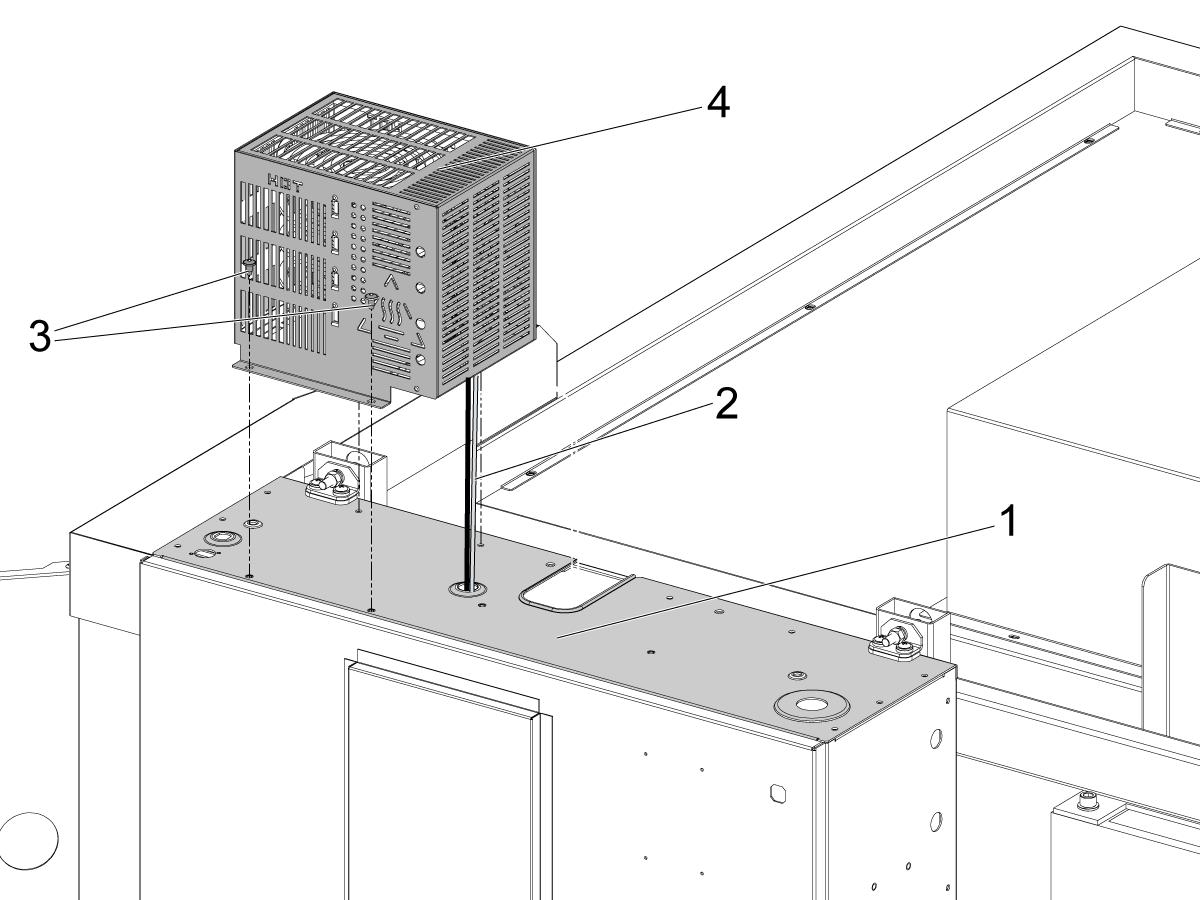
For the DC-2 machine, the regen assembly needs to be installed on top of the control cabinet [1].

Feed the 2 wires [2] connected to the regen assembly through the cutout in the control so that the wires can be routed to the vector drive.

Use the 4 BHCS [3] to install the regen assembly [4] in the correct position on the top of the control

2

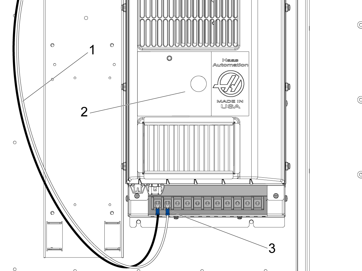
Route the regen cable [1] to through the control cabinet to the vector drive [2].

Connect the cables to terminal 1 and 2 [3] on the bottom of the vector drive according to the label on each cable.

Pendant Installation - DC-Series

1

Fasten the top bracket [1] and the bottom bracket [2] that secure the pendant to the enclosure panel [3].

Use 2 BHCS to secure the top bracket, and 3 BHCS to secure the bottom bracket. 

Feed the cables [4] coming from the top of the enclosure through the top bracket so that they can be connected to the pendant.

Note: Do not damage the cables when fastening the top bracket. Feed the cables through before fastening the bracket if needed.

2

Install the top bracket cover [1] using the 4 BHCS [2] to fasten the cover to the top bracket that is attached to the pendant.

Secure the bottom of the pendant to the mounting bracket by fastening it with a SHCS [3] from underneath the bracket.

Make sure the rubber spacer [4] is in between the pendant and the mounting bracket. Place the one washer on each side of the rubber spacer.

Note: Make sure the top bracket cover doesn't pinch any of the cables that go to the SKBIF PCB.

3

Remove the rear panel of the pendant to gain access to the SKBIF PCB.

Make sure to connect all the cables that were routed through the top pendant mounting bracket that was installed in the previous step.

  • Connect 33-4521 to the connector of 33-1300 which is connected to J20 [1] on the SKBIF PCB.
  • Connect the USB cable to J9 [2] of the SKBIF PCB.
  • Connect the ethernet cable to J28 [3] on the SKBIF PCB.
  • Connect the USB from the touchscreen assembly to J11 [4] on the SKBIF PCB. 
  • Connect the ground wire to the cable clamp fastener [5] as shown in the image.

Note: Make sure that the ferrite filters [6] are installed onto the USB cables to protect them from electrical noise.

Once the wiring has been verified, reinstall the rear panel of the pendant.

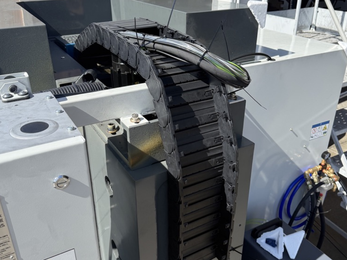
Z-axis Cable Carrier Installation

1

The Z-axis cable carrier needs to be mounted. It is removed on some machines for shipping purposes.

Important: Make sure to verify it is fully installed before you begin jogging the machine.

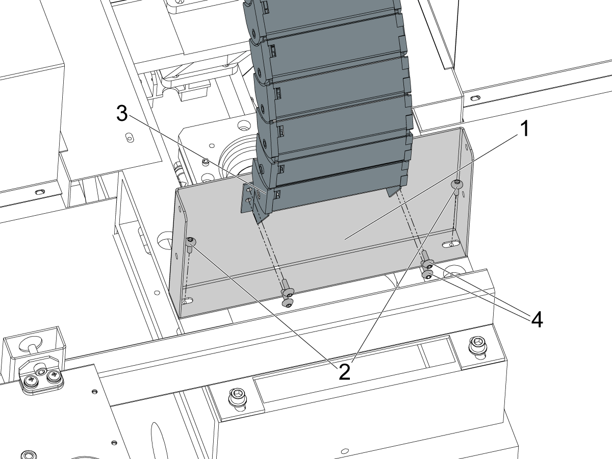
2

The Z-axis cable carrier needs to be mounted. It is removed on some machines for shipping purposes.

Install the cable carrier mount plate [1] to the top of the column using the mounting screws [2].

Then attach the Z-axis carrier [3] to the plate [1] with the 4 BHCS [4].

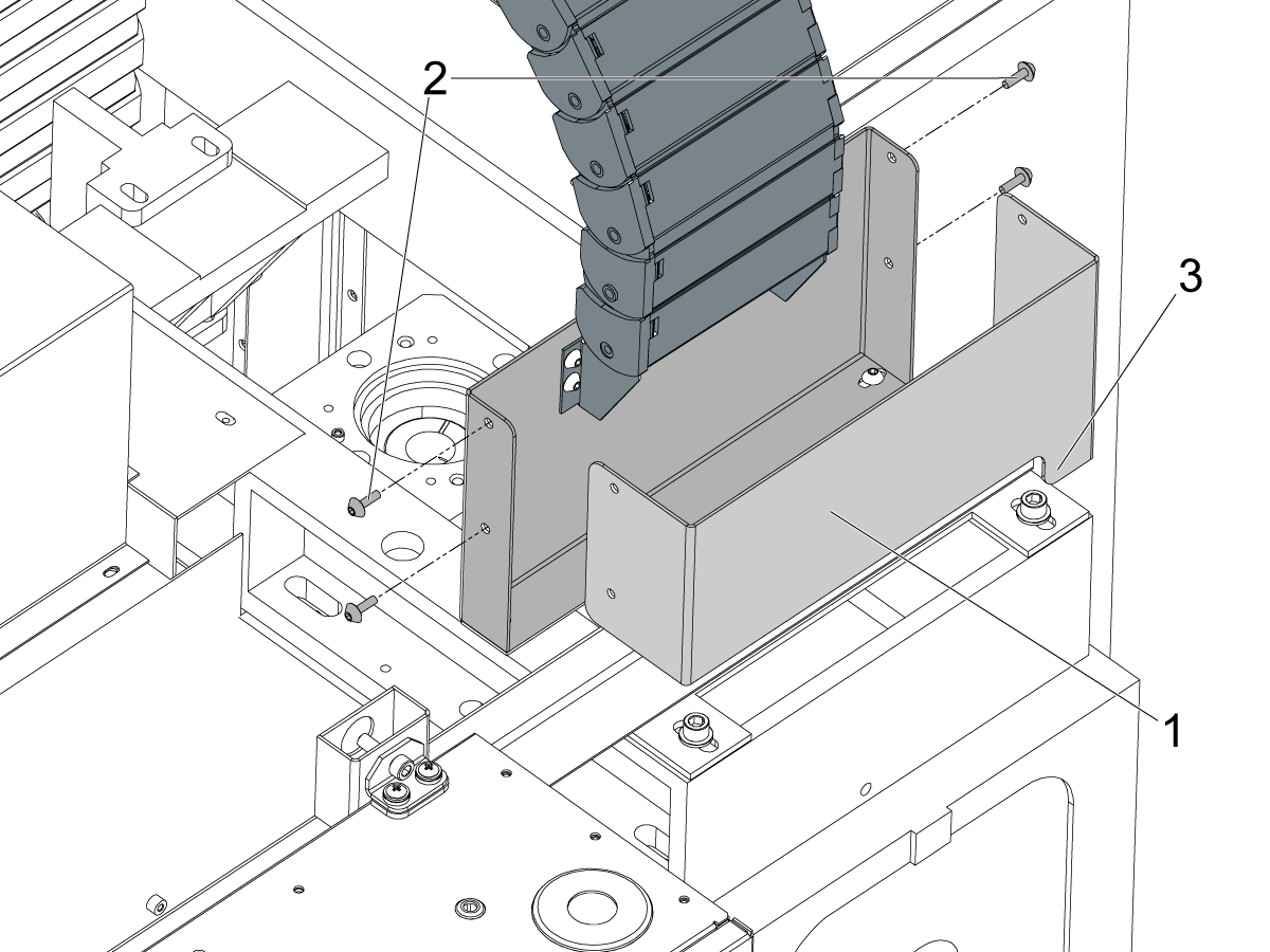
3

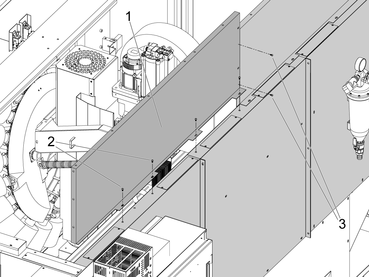
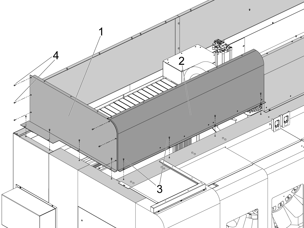
Install the rear cover [1] to the cable carrier mounting plate. 

Use the 4 BHCS [2] to mount the cover to the mounting bracket [3].

Note: Make sure that the cover plate is oriented correctly. The cutout side [4] needs to be on the bottom right side as shown in the image.

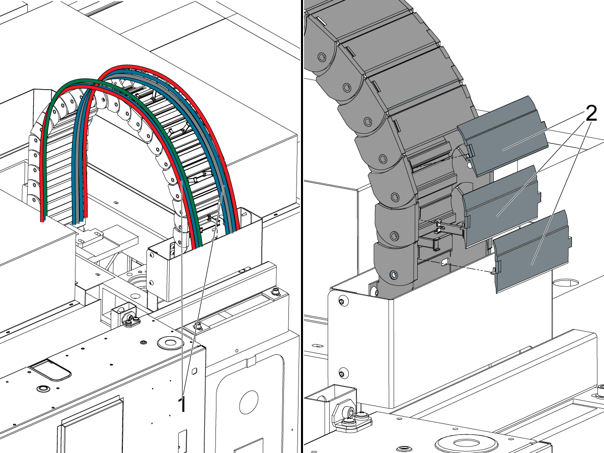
4

 Warning: The cables and hoses need to be separated and pulled to the sides of the cable carrier [1]. Pull them to the left and right sides and don't leave cables or hoses routed in the middle of the cable carrier. The cables could be pinched by some of the mechanical components in the spindle head area.

Once the cables are pulled to the sides, install all the missing links [2] of the cable carrier.

Auto Window Installation

1

For machines with the auto window feature, the auto window needs to be assembled and installed on the right side window of the machine. 

 Important: The machine will be in an alarm state until the auto window and the clamp sensors are properly installed. Continue with these steps and AD0652 for instructions on installing the auto window.

The auto window kit is contained in the 30-14126 package that is shipped with the machine.

Remove the right window enclosure panel [1] from the DC-1 by unfastening the 4 BHCS [2]. 

2

Slide the two window guides [1] onto the side window enclosure panel [2].

To secure the window guides in place, bend the tabs [3] extending from the top of the enclosure panel over the window guides to lock them in position.

Slide the window [4] from the top into the guides [1] and test that the window slides through the guides easily and can be aligned with the window lift bracket [5]. 

 Important: Do not fix the lift bracket [5] to the window at this time. AD0652 provides details on how to complete the auto window installation.

3

Take the auto window mounting panels [1] and fasten them to the DC-2 enclosure [3] as shown in the left image.

Fasten the window panel [4] to the mounting panels [1] using the 6 FBHCS [5] fasteners included in the kit.

 Note: The right image shows the window panel mounting from the viewpoint of inside the machine. Make sure the mounting panels [1] are facing the proper direction.

4

The lift cylinder assembly for the DC-2 auto window is the same as other auto windows for other machines. 

5

Remove the jumper wire (33-1388) [1] from the window close connector of the (33-1169) cable [2]. The 33-1169 cable is connected to P13 of the IO PCB. 

This jumper wire [1] gets replaced by the connector to the window closed sensor [3]. This sensor is on the bottom of the cylinder behind the enclosure cover.

 Note: The purpose of this jumper is to prevent alarms related to the window being open prior to the auto window being installed.

Once this jumper is removed, the Haas control will throw an alarm saying that the side window is not closed.

To clear this alarm, the clamp sensor [3] must be installed onto the auto window lift cylinder.

Refer to AD0652 for instructions on how to install the cylinder and sensors.

6

 Note: Refer to AD0652 - Auto Window Installation for details on installing the window, clamp sensors, and cylinder alignment. AD0652 contains instructions on how to complete the auto window installation and testing for the DC-2 machine. 

Shipping Brackets Removal

1

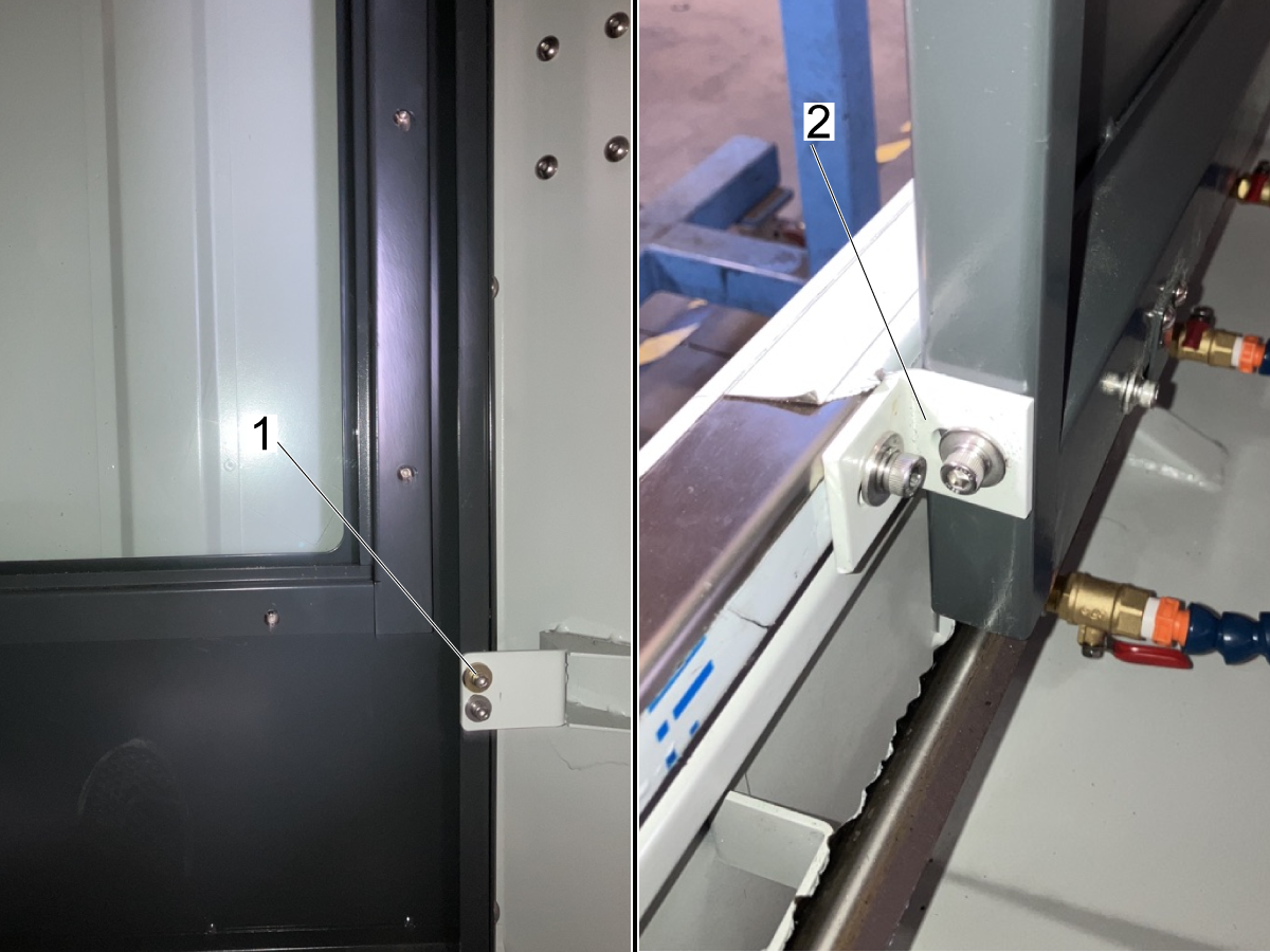
Remove the SHCS keeping the door fastened to the bracket [1].

Note: There are two brackets securing each door in position. One bracket near the door handle [2] and the other bracket on the other end [1].


2

Remove the X-axis and Y-axis shipping brackets. Power on the machine and jog the Z-axis up so that you can remove the spindle head bracket [3] from the table.

 Note: If the Z-axis cannot be jogged up far enough, the Z-axis zero position isn't set correctly. Refer to Chapter 5 - Operation / Tool Changer for details on how to reset the Z-axis zero position. 

3

Once the X-axis and Y-axis shipping brackets have been removed, the waycovers need to be fastened in position.

Remove the front table cover [1] and make sure that all waycover fasteners [2] are removed from the front cover and back side of the table.

 Note: Before jogging along any axis of the machine, make sure the fasteners for the waycovers are removed. 

Once the front cover is removed, use the fasteners removed and the bag of fasteners ziptied to the Y-axis waycover [3].

4

Slide the waycovers into position as shown in the image.

Install the Y-axis waycover [1] to the saddle using the fasteners [2]

Fasten the X-axis waycovers [3] in position using the fasteners [4].

Note: Some of the X-axis waycover fasteners cannot be installed until after the front cover [5] is installed.

Apply RTV sealant to the seams where the waycovers join the table to prevent coolant intrusion under the waycovers.

Install the table front cover [5] that was removed in the previous step.

Note: Make sure that the the fasteners on the back side of the table are secured.

Machine Leveling

1

Zero return each axis one at a time or press [POWER UP]. Go through the leveling process.
Repeat these steps to achieve correct machine level.

2

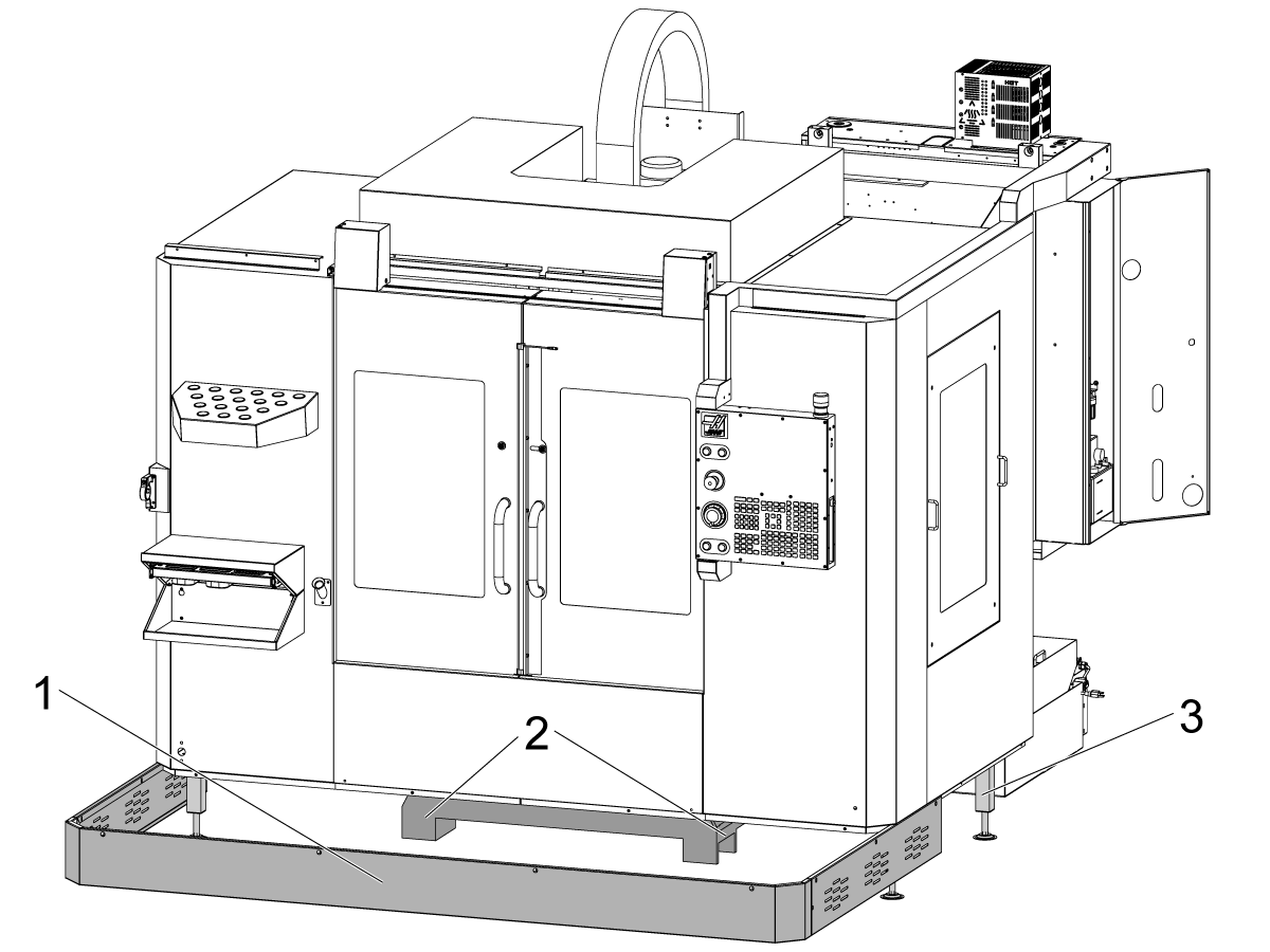
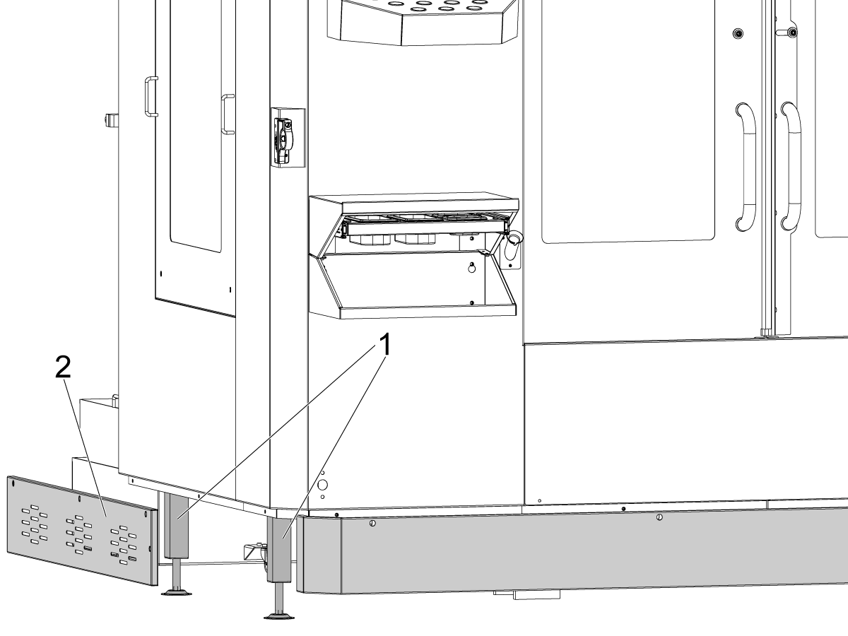
Remove the skirt [1] located at the bottom of the machine.

This will give access to the front two leveling bolts [2]. 

The DC-2 machine has supporting feet [3] near the skirt of the enclosure. 

Important: Make sure these support feet are not touching the ground when doing the leveling process.

3

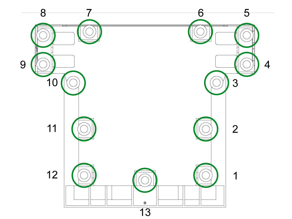
Set the machine height using the four corner leveling bolts [1 ,2, 3, 4] to 4" +/- .5" (101 mm +/- 10 mm) above the floor. Turn each screw so they have equal tension.

Jog the X-axis and Y-axis to the middle of their travel, centering the table.

Note: For more information, refer to this link for a more detailed process on how to level a VMC machine.

VMC Leveling

4

Clean the table surface and leveling tool (T-2181) and check the calibration of the leveling tool before proceeding.

Position the level at the center of the table, parallel to the X-axis. Use a t-slot for alignment.

Note the position of the bubble.

Reposition the level by turning it 180 degrees. The bubble should display the same reading as previously.

If the readings are different by more than one division, return the level to Haas for adjustment and do not use it to level the machine.

5

Adjust corner leveling bolts [1, 2] or [3, 4] until the bubble parallel with the Y-axis is centered.

This levels the machine front to back.

Always raise the lower side of the machine to maintain clearance for the coolant tank (if equipped) and adjust the two leveling bolts on that side an equal amount.

6

Adjust corner leveling bolts [1, 3] or [2, 4] until the bubble parallel to the X-axis is centered.

This levels the machine left to right.

Again, raise the lower side of the machine and adjust the two leveling bolts on that side an equal amount.

7

Keep the level in the same position and jog the Y-axis to bring the table to the front of the machine.

Note the position of the bubble.

Jog the Y-axis across its full travel, stopping at the column. Look to see which rear corner of the machine is lowest, as shown by the leveling tool.

Raise the lowest rear corner by adjusting corner leveling bolt [3] or [4] until the bubble is centered on the level.

8

Jog the Y-axis back across its full travel, bringing the table to the front of the machine. Look to see which front corner is lowest, as shown by the level.

Raise the lowest front corner by adjusting corner leveling bolt [1] or [2] until the bubble is centered on the level.

Repeat steps 6 and 7, moving the table back and forth across the full travel of the Y-axis, raising the lowest corner each time.

Continue this process until the level reads zero at both ends of the Y-axis travel.

9

Once the machine has been leveled along both the X and Y axes, raise up the non-corner leveling bolts [5, 6, and 7] so that they are making contact with the base to provide support.

10

After the machine is leveled, touch down the supporting feet [1] of the enclosure.

Reinstall the machine skirt [2] that was removed before leveling.

Spindle Sweep Check

1

Attach an indicator to spindle head. Position the table and indicator to sweep a circle 10" in diameter.
 
Place a gauge block on the table.
 
Jog the spindle down and zero the indicator at Position 1. 
 
Using a gauge block every 90 degrees, check that the difference in these measurements don't exceed 0.0005". If it does, check the machine level.
 

Lock the leveling bolts in place by tightening the locking nut while holding the leveling bolt. Ensure that the leveling bolts do not move during this process.

For a more in-depth guide on how to perform this procedure, please see:

Spindle Sweep

Spindle Chiller Installation

1

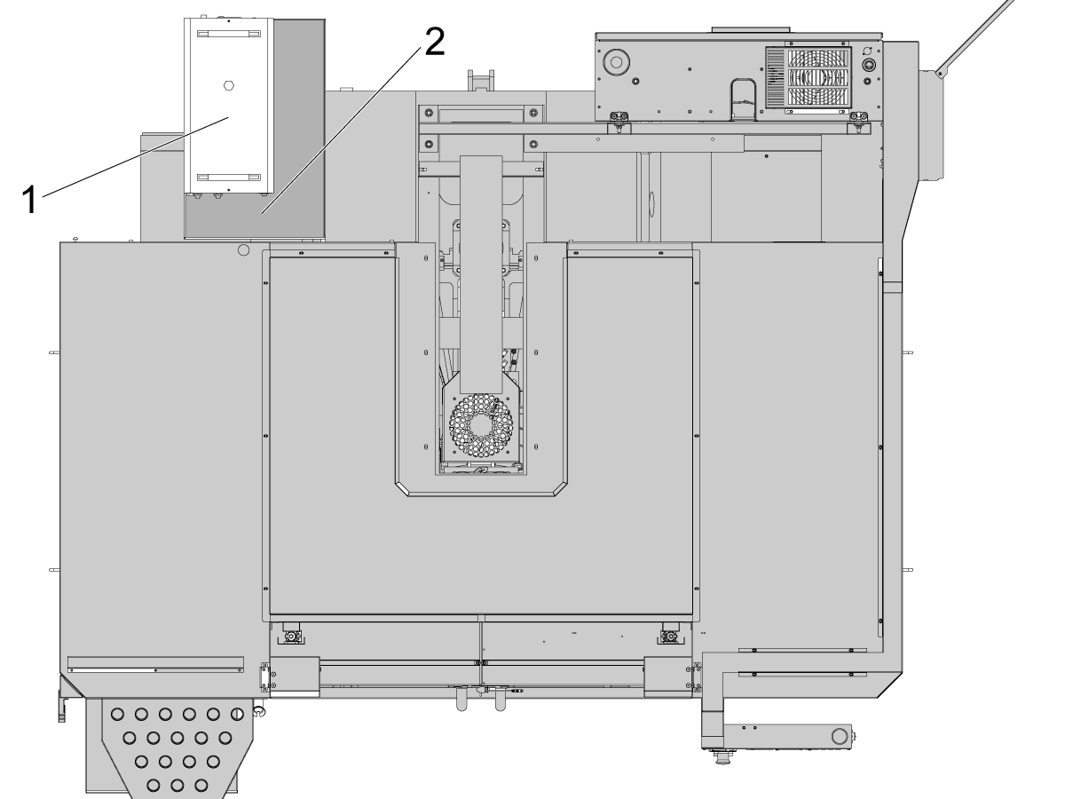
Make sure the spindle chiller is in position [1] on the platform [2] located to the rear of the machine.

There is a power cable, a flow alarm cable, and a ground cable that are installed to the control cabinet at the factory.

Note: Refer to the DC-Series - Spindle Chiller chapter of this manual for more information.

2

Verify that the fluid tank is full by inspecting the fluid level gauge [1] on the back of the spindle chiller unit.

Add fluid if needed through the inlet port at the top of the unit. The fluid gauge should show the level is near the top of the M range [2]. 

Note: Use a mixture of 30% ethylene glycol and 70% dionized water to fill the spindle chiller.

Important: Never run the Spindle Chiller without fluid in the tank. This can cause serious damage to the pump.

3

Make sure that the switch located on the front of the chiller unit is on. The settings and parameters for the chiller are set in the factory and should not be altered.

Note: The display of the spindle chiller will be blank. The chiller powers itself on when the spindle is running or during tool changes. 

Air Lubrication Flow Rate Verification

Verify that the oil reservoir [3] is filled with Mobil DTE 24 Ultra (93-2546).

The flow rate of the oil into the air system also needs to be set correctly. Adjust the set screw [4] so that the flow rate is 1 drop every 3 to 10 minutes. The oil drip will be visible through the sight glass below the set screw [4].

The flow rate of oil into the airlines can only be set when the spindle is running. Run the following MDI program when trying to set the flow rate:

  • S50 M99; 

Loosening the set screw will increase the flow rate of oil, and tightening will decrease the flow rate.

Note: Having a flow rate higher than this range could flood the air supply which could damage the machine.

Axis Lubrication Verification

1

Run the spindle run-in program.

Examine the sight glass, make sure the correct number of drops fall through the sight glass. 

Examine the fittings [1,2] on top of the oil pump tank.

The oil collects on top of the oil pump tank [3] either behind or in front of the sight glass bracket, underneath the leaking fitting.

Tighten any leaking fittings.

2

Go to the Maintenance tab.

Press [F2] to cycle an axis lubrication test.

Inspect the gauge on the grease lubrication system. Make sure it holds pressure.

Single/Dual Programmable Air Option

1

Machines with Single/Dual Prog Air Option Only: 

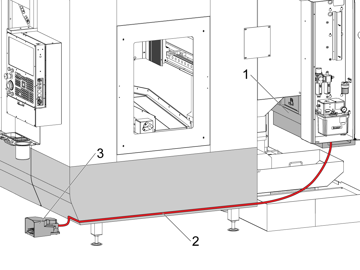
Route the Foot Pedal cable (32-1390) [1] from the control [2]along the enclosure panels to the front of the machine [3].

For more details, refer to the Programmable Air Installation procedure.

Coolant Tank Installation

1

Power off the machine.

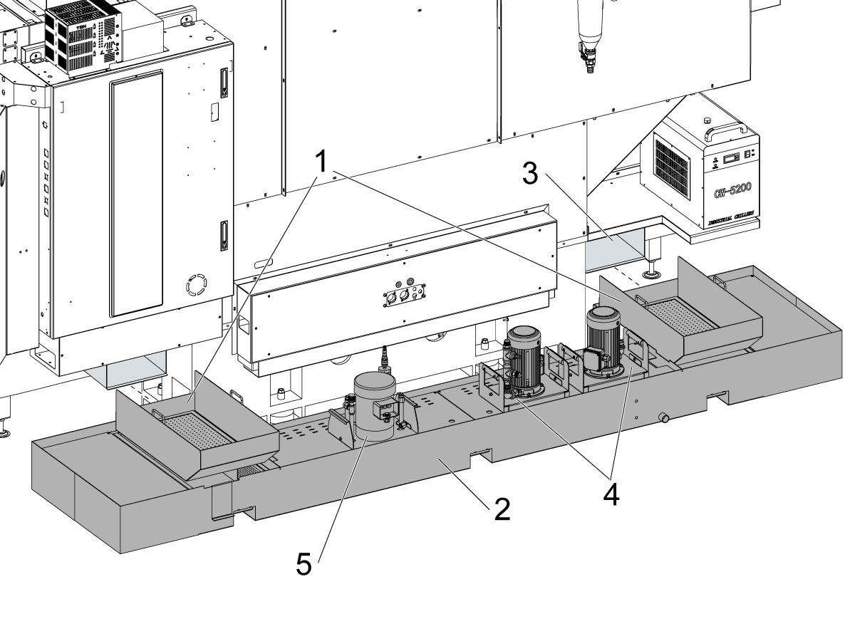
Place the 2 chip strainer baskets [1] into the coolant tank [2].

Move the coolant tank assembly under the drain slots [3] at the base of the machine.

 NOTE: Make sure that the strainer basket [1] is directly under the drain slots to ensure coolant flows into the tank. 

Place the TSC pump on the left [4] if included in machine. Place the flood coolant pump on the right [5].

2

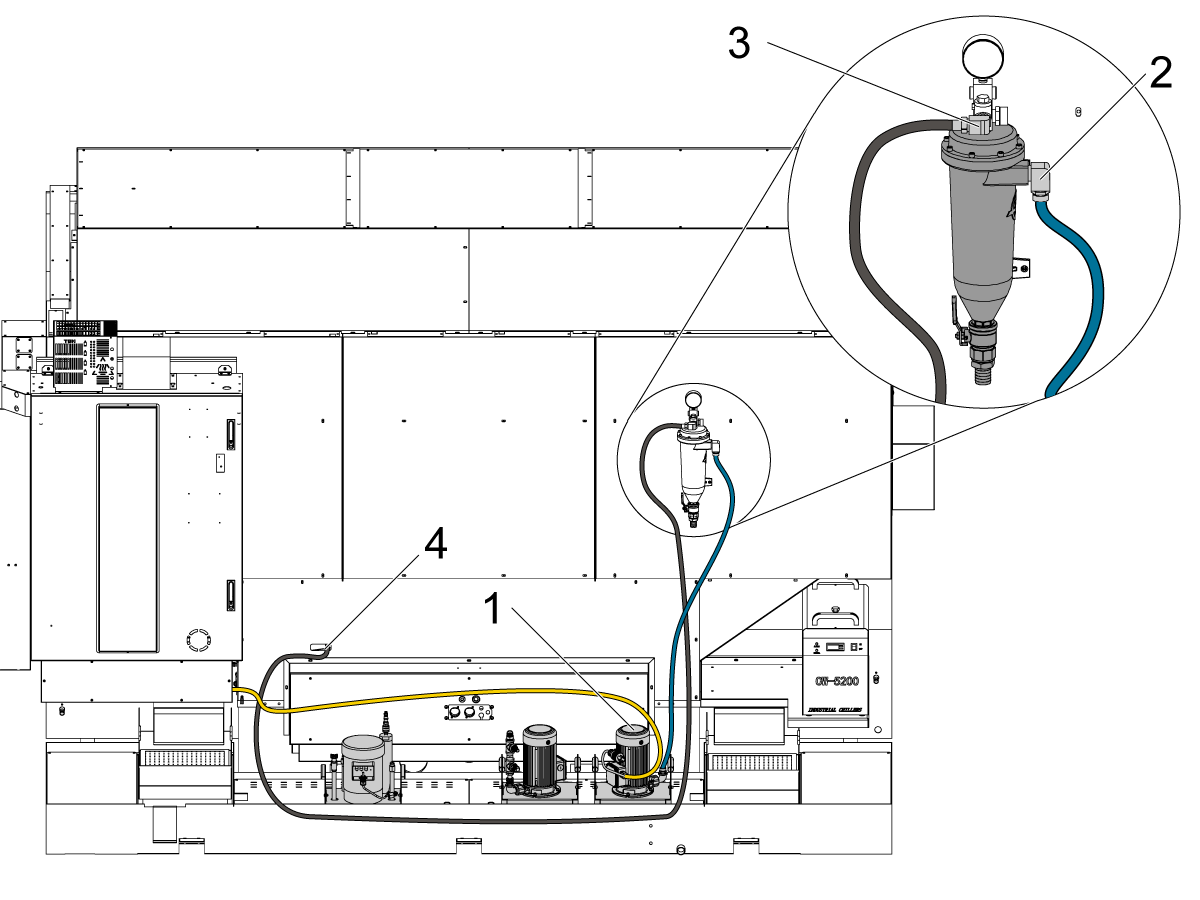
Connect the hose coming from the coolant pump [1] to the end of the chip separator [2].

Connect the hose from the T-fitting [3] to the coolant washdown going to the left side of the machine (right side as shown in the image from the back of machine)

Connect the hose from the right side of the chip separator [4] to the other side coolant washdown. Route the hose through the column casting to the far side of the machine.

Connect the hose coming from the spindle head [5] to the front fitting on the chip separator [6].

Connect the hose [7] to the coolant gun port on the front of the machine. Route it through the enclosure with the hose for the coolant washdown.

Option Installation Guides

Verify and test that all the machine options have been properly installed.

Remote Jog Handle XL (RJH-XL) - Installation
Wi-Fi Camera Installation
Convenience Package
Auxilary Coolant Filter
CABCOOL installation
HPFC Installation
Haas Cobot 10 Installation
Auto Door Install
Haas Oil Skimmer Installation
Table work light
Tool Air Blast
WIPS Installation
AutoWindow Install
Dual Programmable Air
Programmable Air
Coolant Sanitizer

Final Testing

1

Spindle Operation 

Run the Spindle Run-In program O09221. 

In the case of an unusual spindle noise, run a vibration test. For a guide on how to perform a spindle vibration test please see: 

Vibration Analysis - Ethernet Interface
Vibration Analysis - RS-232 Interface

2

Coolant and Air Blast-DC Operation

Fill the coolant tank with the necessary gallons of coolant in order to fill the tank.

Connect the coolant pump.

Run coolant by pressing  [COOLANT] on control pendant.

Verify that there is coolant coming out of the nozzles around the machine.

There are two nozzles for coolant located by the spindle head. Make sure coolant comes out of the two nozzles on the left.

Note: The third nozzle by the spindle head is for the Air Blast-DC option. Refer to the decal [1] for which nozzles are for coolant.

To verify that the Air Blast option is operational, run the following command in MDI mode and make sure air comes out of the nozzle labeled AIR BLAST:

  1. M83 - starts the air blast
  2. M84 - stops the air blast

3

Through Spindle Coolant (TSC) 

If machine comes equipped with TSC, insert a TSC toolholder into the tool carousel side pocket.

Then load the toolholder into the spindle by calling T[pocket_number] on the control and pressing ATC FWD.

Important: Tools cannot be loaded directly into the spindle on a DC machine. For more details on how to load tools into the spindle for the DC machine, refer to the Operation Chapter.

Press [AUX CLNT] to start the TSC.

Correct operation is as follows:

  1. Coolant flows correctly from the TSC tool holder.
  2. A few drops flow from the vacuum-generator hose [2].

Press [RESET].

4

Through-Tool Air Blast (TAB)

If machine comes equipped with TAB, operate this code in MDI mode:

M73;

G04 P5.;

M74;

G04 P3.;

M99;

M73 starts the TAB. M74 stops the TAB.

Manually operate the TAB:

Press [AUX CLNT]. Press the [RIGHT] cursor arrow.

The tool air blast starts.

Press [AUX CLNT].

The tool air blast stops.

5

Door Interlock

Press [MDI]. Type in S500 M3; Press [ENTER].

Make sure the machine IS NOT in SETUP MODE by checking the KEY SWITCH on the side of the pendant

With the door open, press [CYCLE START]. The machine should say to close the door and press [CYCLE START].

With the door closed, press [CYCLE START]. The interlock pin should extend and the spindle starts rotating.

 IMPORTANT: With the spindle rotating, test the door locks by trying to open the door. The spindle should not stop rotating. 

6

Test Key Switches

Insert the Setup/Run Lock Key (#2007) to the lower key slot and turn to the unlocked position.

Verify that the key can only be removed from the locked position.

Insert the Memory Lock Key (#2341) to the upper key slot and turn to the locked position.

Verify that the key can be removed from either position.

With the Memory Lock Key in the locked position, verify that changes cannot be made to the settings or programs.

7

Auto Window Installation

If machine has the auto window option, refer to Auto Window Installation - AD0652 for information on how to install the auto window on the DC-2.

Assemble the window enclosure.

Bolt the bottom bracket [1] to the enclosure above the window. 

Loosen the sensor clamp [2] on the bottom of the air cylinder.  Insert sensor [3] in between clamp and piston rod. Before tightening the sensor clamp, refer to the Auto Window - Troubleshooting Guide for sensor location. 

Remove the fitting plugs on the top and bottom of the air cylinder.  Connect the yellow airline [4] to the bottom hose fitting and the grey airline [5] to the top hose fitting. 

Reinstall enclosure cover. 

To test the auto window, operate this code in MDI mode:

M59 P151;

G04 P5.;

M69 P151;

G04 P5.;

M99;

8

Rotary Installation

If your machine came with a HRT or TRT rotary table please see the following link for installation instructions:

Rotary Installation

9

WIPS Calibration 

If your machine includes the WIPS option, please see the following link for instructions on the calibration procedure:

WIPS Calibration NGC

10

Wifi Camera Operation 

If the machine came with the Wifi Camera option, please see the following link for installation instructions:

Wi-fi Camera Installation

DC-Series Maintenance Schedule

Keep your Haas machines running at peak performance while avoiding unplanned downtime. A maintenance program allows you to manage your schedule rather than getting caught with untimely surprises. Please see the link below for recommended maintenance intervals for this machine.


DC-Series MAINTENANCE

4.3 DC-3 - Installation

Recently Updated

DC-3 Installation


Under Construction

Revision A - 8/2025

Introduction

This procedure will guide you through the installation of the DC-3 40-taper machines.

Tools required:

  • Precision Machinist Level, 0.0005" Division
  • 23mm socket and ratchet
  • 40mm wrench
  • 20 mm socket
  • Tape Measure
  • 0.0005" or 1 micron indicator 

The DC-3 can be lifted by forklift, or by using the lifting points on the base and column castings. For details on how to lift the DC-3 refer to the Pre-Installation Guide, or the machine lifting placard [1] located on the machine.

The DC-3 machine weighs XXXX lbs (XXXX kg). Check the specification of the lifting equipment before trying to lift.

 Important: The DC-3 machine is required to be anchored. See section 4.5 Anchoring for the anchoring kit part number and instructions.

Remove Rust Inhibitor

To safely and effectively remove rust inhibitor from way covers and other non-painted surfaces:

Initial Scraping

  • Use a plastic scraper to remove the bulk of the rust inhibitor.
  • Avoid using metal tools to prevent scratching or damaging the surface.

 Important: Do not use scotch-brite or metal scrapers, these will scratch the way covers.

Chemical Cleaning

  • Spray the affected areas with a heavy-duty citrus cleaner or Simple Green.
  • Ensure full coverage of all non-painted surfaces coated with rust inhibitor.

 Note: If there is rust inhibitor left over that is difficult to remove with simple green, use brake cleaner.

Air Connection

1

Connect the Air Supply at the lube panel shown in the image as Input Air Supply.

Note: For air specifications refer to the decal located on the front of the lube cabinet door.

The required air pressure for the DC-3 machine is 85psi.

Connect the air supply and verify the pressure gauge [1] on the regulator shows the correct pressure.

If the pressure needs to be adjusted, pull the regulator cap [2] up, and then twist it to set the outgoing air to 85 psi.

Once the gauge reads 85 psi, push the regulator cap down to lock it in place.

Electrical Installation

 DANGER: Working with the electrical services required for CNC machines is extremely hazardous and can result in serious injury or death.

Before connecting line wires to the CNC:

  • Turn off all power to the machine at the source.
  • Perform a Lockout-Tagout (LOTO) procedure to ensure the power remains off during service.
  • Verify that power has been disconnected by using an AC voltage detector on all incoming lines.

If you are uncertain about how to safely disconnect power or perform LOTO procedures:

  • Do not proceed.
  • Contact qualified personnel or obtain appropriate assistance before continuing.

Failure to follow these precautions may result in electrical shock, equipment damage, or fatal injury.

1

Initial Control Inspection

Danger: At this point, there should be no electrical connection to the machine. Electrical panel must be closed and secured. When main switch is on, there is HIGH VOLTAGE throughout the electrical panel (including the circuit boards and logic circuits) and some components operate at high temperatures. Therefore, exercise extreme caution when working in the panel.

  • Set the main breaker switch at the upper right of the electrical panel on the back of the machine to OFF.
  • Using a screwdriver, unlock the two latches on the panel door, unlock the cabinet with the key and open the door.
  • Take sufficient time to check all the components and connectors associated with the circuit boards. Look for any cables that have become disconnected, look for any signs damage and loose parts in the bottom of the panel box. If there are any signs that the machine was mishandled, call the factory before proceeding.

2

1-Phase Machines: Insert each power lead into the wire cover.  Connect the two power leads to L1 and L3 terminals on top of the main circuit breaker.

3-Phase Machines: Insert each power lead into the wire cover.  Connect the three power leads to L1, L2 and L3 terminals on top of the main circuit breaker.

Connect the separate ground line to the ground bus to the left of the terminals.

For 3-phase machines, check to see what type of power configuration is supplying the machine. Take voltage measurements of each power lead to ground line. Then refer to RD0084 - Input Power Configurations to determine which power lead should be connected to the L1 terminal based of the voltage readings and power configuration.

Refer to Haas Main Circuit Breaker - Torque Specifications for what value to torque the circuit breaker power leads.

 Note: Make sure that the leads actually go into the terminal-block clamps . (A poor connection will cause the machine to run intermittently or have other problems, such as servo overloads.) To check, simply pull on the wires after the screws are tightened.

3

After the line voltage is connected to the machine, make sure that main circuit breaker (at top-right of rear cabinet) is OFF . Remove the Lockout / Tagout and Turn ON the power at the source. Using a digital voltmeter and appropriate safety procedures: 

1-Phase Machines: Measure the AC voltage across L1 & L3 at the main circuit breaker.  The AC voltage must be between 220 - 250 volts .
Note: Lower or higher than this voltage can generate low/high voltage alarms.

3-Phase Machines : Measure the AC voltage between all three pair phases at the main circuit breaker. 

The AC voltage must be between 195 and 260 volts (360 and 480 volts for high voltage option).

SMinimill - Reboot: The AC voltage must be between 198 and 242 volts for machines without a high voltage transformer.  Refer to the Minimill/SMinimill - Identification document.

 Note: Wide voltage fluctuations are common in many industrial areas; minimum and maximum voltage supplied to a machine while it is in operation must be known. U.S. National Electrical Code specifies that machines should operate with a variation of +5% to -5% around an average supply voltage. If problems with line voltage occur, or low line voltage is suspected, an external transformer may be used. If you suspect voltage problems, voltage should be checked every hour or two during a typical day to be sure it does not fluctuate more than +5% or -5% from an average.

4

Important: With the main circuit breaker turned OFF.

Check the transformer taps at the bottom-right corner of the rear cabinet.

1-Phase Machines: The input voltage cable must be moved to the connector which corresponds to the average voltage measured in the above step.

3-Phase Machines:  The input voltage cables labeled 74, 75, and 76 must be moved to the terminal block triple which corresponds to the average voltage measured in the above step.

5

Transformer T5 supplies 24VAC used to power the main contactor. There are two versions of this transformer for use on a 240 and 400V machines. The 240V transformer has two input connectors located about two inches from the transformer, which allow it to be connected to either 180-220V or 221-240V.

Users that have 220V-240V RMS input power should use the connector labeled 221-240V, while users with 190-220V input power should use the connector labeled 180-220V. Failure to use the correct input connector will result in either overheating of the main contactor or failure to reliably engage the main contactor.

The 480V (option) T5 transformer has three input connectors, labeled 340-380V, 381-440V and 441-480V.

Users with 340-380V 50/60Hz power should use the 340-380V connector while users with 380V-440V 50/60Hz power should use the 381-440V connector.

Important: Set the main circuit breaker to ON. Check for evidence of problems, such as the smell of overheating components or smoke. If such problems are indicated, immediately set the main circuit breaker to OFF and call the factory before proceeding.

After the power is on, measure the voltage across the bottom terminals on the main circuit breaker. It should be the same as the measurements where the input power connects to the main breaker. If there are any problems, check the wiring.

6

Apply power to the control by pressing the Power-On switch on the front panel.

Check the DC Voltage and AC Line Voltage gauges in Diagnostics. The DC Voltage gauge must read between 310 - 360V. The AC Line Voltage must be between 90 and 105 percent. If the voltage is outside these limits, turn off the power and recheck steps 2 and 3. If the voltage is still outside these limits, call the factory.

7

Electrical power must be phased properly to avoid damage to your equipment. The Power Supply Assembly PC board incorporates a "Phase Detect" circuit with neon indicators. When the orange neon is lit (NE5), the phasing is incorrect. If the green neon is lit (NE6), the phasing is correct. If both neon indicators are lit, you have a loose wire; check the connections. Adjust phasing by setting the source power to off and then swapping L1 and L2 of the incoming power lines at the main circuit breaker.

Danger: ALL POWER TO CNC MUST BE TURNED OFF LOCKOUT-TAGOUT AT THE SOURCE PRIOR TO ADJUSTING PHASING. ALWAYS DOUBLE CHECK THE INCOMING LINES WITH AN AC VOLTAGE DETECTOR.

Turn off the power and set the main circuit breaker to OFF. Close the door, lock the latches, and turn the power back on.

Remove the key from the control cabinet and give it to the shop manager.

8

Activation

When the machine is properly placed and connected to both air and electrical power, it is ready for final installation (removing shipping blocks, leveling, spindle sweep, etc.) and software activation. The HFO service technician does this. Contact the local HFO to schedule the work.

IMPORTANT:  Machines equipped with motion sensors must be rough‑leveled before attempting to arm the motion sensor.  For detailed instructions, refer to Service Notification - SA0007.  Access to this document is restricted to Haas Factory Outlet personnel.

Spindle Sweep Check

1

Attach an indicator to spindle head. Position the table and indicator to sweep a circle 10" in diameter.
 
Place a gauge block on the table.
 
Jog the spindle down and zero the indicator at Position 1. 
 
Using a gauge block every 90 degrees, check that the difference in these measurements don't exceed 0.0005". If it does, check the machine level.
 

Lock the leveling bolts in place by tightening the locking nut while holding the leveling bolt. Ensure that the leveling bolts do not move during this process.

For a more in-depth guide on how to perform this procedure, please see:

Spindle Sweep

Spindle Chiller Installation

1

Make sure the spindle chiller [1] is in position on the platform [2] located to the rear of the machine.

There is a power cable, a flow alarm cable, and a ground cable that are installed to the control cabinet at the factory.

Note: Refer to the DC-Series - Spindle Chiller chapter of this manual for more information.

2

Verify that the fluid tank is full by inspecting the fluid level gauge [1] on the back of the spindle chiller unit.

Add fluid if needed through the inlet port at the top of the unit. The fluid gauge should show the level is near the top of the M range [2]. 

Note: Use a mixture of 30% ethylene glycol and 70% dionized water to fill the spindle chiller.

Important: Never run the Spindle Chiller without fluid in the tank. This can cause serious damage to the pump.

3

Make sure that the switch located on the front of the chiller unit is on. The settings and parameters for the chiller are set in the factory and should not be altered.

Note: The display of the spindle chiller will be blank. The chiller powers itself on when the spindle is running or during tool changes. 

Air Lubrication Flow Rate Verification

Verify that the oil reservoir [3] is filled with Mobil DTE 24 Ultra (93-2546).

The flow rate of the oil into the air system also needs to be set correctly. Adjust the set screw [4] so that the flow rate is 1 drop every 3 to 10 minutes. The oil drip will be visible through the sight glass below the set screw [4].

The flow rate of oil into the airlines can only be set when the spindle is running. Run the following MDI program when trying to set the flow rate:

  • S50 M99; 

Loosening the set screw will increase the flow rate of oil, and tightening will decrease the flow rate.

Note: Having a flow rate higher than this range could flood the air supply which could damage the machine.

Axis Lubrication Verification

1

Run the spindle run-in program.

Examine the sight glass, make sure the correct number of drops fall through the sight glass. 

Examine the fittings [1,2] on top of the oil pump tank.

The oil collects on top of the oil pump tank [3] either behind or in front of the sight glass bracket, underneath the leaking fitting.

Tighten any leaking fittings.

2

Go to the Maintenance tab.

Press [F2] to cycle an axis lubrication test.

Inspect the gauge on the grease lubrication system. Make sure it holds pressure.

Coolant Tank Installation

1

Power off the machine.

Place the 2 chip strainer baskets [1] into the coolant tank [2].

Move the coolant tank assembly under the drain slots [3] at the base of the machine.

 NOTE: Make sure that the strainer basket [1] is directly under the drain slots to ensure coolant flows into the tank. 

Place the TSC pump on the left [4] if included in machine. Place the flood coolant pump on the right [5].

2

Connect the hose coming from the coolant pump [1] to the end of the chip separator [2].

Connect the hose from the T-fitting [3] to the coolant washdown going to the left side of the machine (right side as shown in the image from the back of machine)

Connect the hose from the right side of the chip separator [4] to the other side coolant washdown. Route the hose through the column casting to the far side of the machine.

Connect the hose coming from the spindle head [5] to the front fitting on the chip separator [6].

Connect the hose [7] to the coolant gun port on the front of the machine. Route it through the enclosure with the hose for the coolant washdown.

Option Installation Guides

Verify and test that all the machine options have been properly installed.

Remote Jog Handle XL (RJH-XL) - Installation
Wi-Fi Camera Installation
Convenience Package
Auxilary Coolant Filter
CABCOOL installation
HPFC Installation
Haas Cobot 10 Installation
Auto Door Install
Haas Oil Skimmer Installation
Table work light
Tool Air Blast
WIPS Installation
AutoWindow Install
Dual Programmable Air
Programmable Air
Coolant Sanitizer

Final Testing

1

Spindle Operation 

Run the Spindle Run-In program O09221. 

In the case of an unusual spindle noise, run a vibration test. For a guide on how to perform a spindle vibration test please see: 

Vibration Analysis - Ethernet Interface
Vibration Analysis - RS-232 Interface

2

Coolant and Air Blast-DC Operation

Fill the coolant tank with the necessary gallons of coolant in order to fill the tank.

Connect the coolant pump.

Run coolant by pressing  [COOLANT] on control pendant.

Verify that there is coolant coming out of the nozzles around the machine.

There are two nozzles for coolant located by the spindle head. Make sure coolant comes out of the two nozzles on the left.

Note: The third nozzle by the spindle head is for the Air Blast-DC option. Refer to the decal [1] for which nozzles are for coolant.

To verify that the Air Blast option is operational, run the following command in MDI mode and make sure air comes out of the nozzle labeled AIR BLAST:

  1. M83 - starts the air blast
  2. M84 - stops the air blast

3

Through Spindle Coolant (TSC) 

If machine comes equipped with TSC, insert a TSC toolholder into the tool carousel side pocket.

Then load the toolholder into the spindle by calling T[pocket_number] on the control and pressing ATC FWD.

Important: Tools cannot be loaded directly into the spindle on a DC machine. For more details on how to load tools into the spindle for the DC machine, refer to the Operation Chapter.

Press [AUX CLNT] to start the TSC.

Correct operation is as follows:

  1. Coolant flows correctly from the TSC tool holder.
  2. A few drops flow from the vacuum-generator hose [2].

Press [RESET].

4

Through-Tool Air Blast (TAB)

If machine comes equipped with TAB, operate this code in MDI mode:

M73;

G04 P5.;

M74;

G04 P3.;

M99;

M73 starts the TAB. M74 stops the TAB.

Manually operate the TAB:

Press [AUX CLNT]. Press the [RIGHT] cursor arrow.

The tool air blast starts.

Press [AUX CLNT].

The tool air blast stops.

5

Door Interlock

Press [MDI]. Type in S500 M3; Press [ENTER].

Make sure the machine IS NOT in SETUP MODE by checking the KEY SWITCH on the side of the pendant

With the door open, press [CYCLE START]. The machine should say to close the door and press [CYCLE START].

With the door closed, press [CYCLE START]. The interlock pin should extend and the spindle starts rotating.

 IMPORTANT: With the spindle rotating, test the door locks by trying to open the door. The spindle should not stop rotating. 

6

Test Key Switches

Insert the Setup/Run Lock Key (#2007) to the lower key slot and turn to the unlocked position.

Verify that the key can only be removed from the locked position.

Insert the Memory Lock Key (#2341) to the upper key slot and turn to the locked position.

Verify that the key can be removed from either position.

With the Memory Lock Key in the locked position, verify that changes cannot be made to the settings or programs.

7

Rotary Installation

If your machine came with a HRT or TRT rotary table please see the following link for installation instructions:

Rotary Installation

8

WIPS Calibration 

If your machine includes the WIPS option, please see the following link for instructions on the calibration procedure:

WIPS Calibration NGC

9

Wifi Camera Operation 

If the machine came with the Wifi Camera option, please see the following link for installation instructions:

Wi-fi Camera Installation

DC-Series Maintenance Schedule

Keep your Haas machines running at peak performance while avoiding unplanned downtime. A maintenance program allows you to manage your schedule rather than getting caught with untimely surprises. Please see the link below for recommended maintenance intervals for this machine.


DC-Series MAINTENANCE

4.4 DC-4 - Installation

Recently Updated

DC-4 Installation


Revision C - 05/2026

Introduction

This procedure will guide you through the installation of the DC-4 40-taper machines.

Tools required:

  • Precision Machinist Level, 0.0005" Division
  • 23mm socket and ratchet
  • 40mm wrench
  • 20 mm socket
  • Tape Measure
  • 0.0005" or 1 micron indicator 

The DC-4 can be lifted by forklift, or by using the lifting points on the base and column castings. For details on how to lift the DC-4 refer to the Pre-Installation Guide, or the machine lifting placard [1] located on the machine.

The DC-4 machine weighs 12500 lbs (5669 kg). Check the specification of the lifting equipment before attempting to lift.

 Important: The DC-4 machine is required to be anchored. See section 4.5 Anchoring for the anchoring kit part number and instructions.

Remove Rust Inhibitor

To safely and effectively remove rust inhibitor from way covers and other non-painted surfaces:

Initial Scraping

  • Use a plastic scraper to remove the bulk of the rust inhibitor.
  • Avoid using metal tools to prevent scratching or damaging the surface.

 Important: Do not use scotch-brite or metal scrapers, these will scratch the way covers.

Chemical Cleaning

  • Spray the affected areas with a heavy-duty citrus cleaner or Simple Green.
  • Ensure full coverage of all non-painted surfaces coated with rust inhibitor.

 Note: If there is rust inhibitor left over that is difficult to remove with simple green, use brake cleaner.

Air Connection

1

Connect the Air Supply at the lube panel shown in the image as Input Air Supply.

Note: For air specifications refer to the decal located on the front of the lube cabinet door.

The required air pressure for the DC-4 machine is 85psi.

Connect the air supply and verify the pressure gauge [1] on the regulator shows the correct pressure.

If the pressure needs to be adjusted, pull the regulator cap [2] up, and then twist it to set the outgoing air to 85 psi.

Once the gauge reads 85 psi, push the regulator cap down to lock it in place.

Electrical Installation

 DANGER: Working with the electrical services required for CNC machines is extremely hazardous and can result in serious injury or death.

Before connecting line wires to the CNC:

  • Turn off all power to the machine at the source.
  • Perform a Lockout-Tagout (LOTO) procedure to ensure the power remains off during service.
  • Verify that power has been disconnected by using an AC voltage detector on all incoming lines.

If you are uncertain about how to safely disconnect power or perform LOTO procedures:

  • Do not proceed.
  • Contact qualified personnel or obtain appropriate assistance before continuing.

Failure to follow these precautions may result in electrical shock, equipment damage, or fatal injury.

1

Initial Control Inspection

Danger: At this point, there should be no electrical connection to the machine. Electrical panel must be closed and secured. When main switch is on, there is HIGH VOLTAGE throughout the electrical panel (including the circuit boards and logic circuits) and some components operate at high temperatures. Therefore, exercise extreme caution when working in the panel.

  • Set the main breaker switch at the upper right of the electrical panel on the back of the machine to OFF.
  • Using a screwdriver, unlock the two latches on the panel door, unlock the cabinet with the key and open the door.
  • Take sufficient time to check all the components and connectors associated with the circuit boards. Look for any cables that have become disconnected, look for any signs damage and loose parts in the bottom of the panel box. If there are any signs that the machine was mishandled, call the factory before proceeding.

2

1-Phase Machines: Insert each power lead into the wire cover.  Connect the two power leads to L1 and L3 terminals on top of the main circuit breaker.

3-Phase Machines: Insert each power lead into the wire cover.  Connect the three power leads to L1, L2 and L3 terminals on top of the main circuit breaker.

Connect the separate ground line to the ground bus to the left of the terminals.

For 3-phase machines, check to see what type of power configuration is supplying the machine. Take voltage measurements of each power lead to ground line. Then refer to RD0084 - Input Power Configurations to determine which power lead should be connected to the L1 terminal based of the voltage readings and power configuration.

Refer to Haas Main Circuit Breaker - Torque Specifications for what value to torque the circuit breaker power leads.

 Note: Make sure that the leads actually go into the terminal-block clamps . (A poor connection will cause the machine to run intermittently or have other problems, such as servo overloads.) To check, simply pull on the wires after the screws are tightened.

3

After the line voltage is connected to the machine, make sure that main circuit breaker (at top-right of rear cabinet) is OFF . Remove the Lockout / Tagout and Turn ON the power at the source. Using a digital voltmeter and appropriate safety procedures: 

1-Phase Machines: Measure the AC voltage across L1 & L3 at the main circuit breaker.  The AC voltage must be between 220 - 250 volts .
Note: Lower or higher than this voltage can generate low/high voltage alarms.

3-Phase Machines : Measure the AC voltage between all three pair phases at the main circuit breaker. 

The AC voltage must be between 195 and 260 volts (360 and 480 volts for high voltage option).

SMinimill - Reboot: The AC voltage must be between 198 and 242 volts for machines without a high voltage transformer.  Refer to the Minimill/SMinimill - Identification document.

 Note: Wide voltage fluctuations are common in many industrial areas; minimum and maximum voltage supplied to a machine while it is in operation must be known. U.S. National Electrical Code specifies that machines should operate with a variation of +5% to -5% around an average supply voltage. If problems with line voltage occur, or low line voltage is suspected, an external transformer may be used. If you suspect voltage problems, voltage should be checked every hour or two during a typical day to be sure it does not fluctuate more than +5% or -5% from an average.

4

Important: With the main circuit breaker turned OFF.

Check the transformer taps at the bottom-right corner of the rear cabinet.

1-Phase Machines: The input voltage cable must be moved to the connector which corresponds to the average voltage measured in the above step.

3-Phase Machines:  The input voltage cables labeled 74, 75, and 76 must be moved to the terminal block triple which corresponds to the average voltage measured in the above step.

5

Transformer T5 supplies 24VAC used to power the main contactor. There are two versions of this transformer for use on a 240 and 400V machines. The 240V transformer has two input connectors located about two inches from the transformer, which allow it to be connected to either 180-220V or 221-240V.

Users that have 220V-240V RMS input power should use the connector labeled 221-240V, while users with 190-220V input power should use the connector labeled 180-220V. Failure to use the correct input connector will result in either overheating of the main contactor or failure to reliably engage the main contactor.

The 480V (option) T5 transformer has three input connectors, labeled 340-380V, 381-440V and 441-480V.

Users with 340-380V 50/60Hz power should use the 340-380V connector while users with 380V-440V 50/60Hz power should use the 381-440V connector.

Important: Set the main circuit breaker to ON. Check for evidence of problems, such as the smell of overheating components or smoke. If such problems are indicated, immediately set the main circuit breaker to OFF and call the factory before proceeding.

After the power is on, measure the voltage across the bottom terminals on the main circuit breaker. It should be the same as the measurements where the input power connects to the main breaker. If there are any problems, check the wiring.

6

Apply power to the control by pressing the Power-On switch on the front panel.

Check the DC Voltage and AC Line Voltage gauges in Diagnostics. The DC Voltage gauge must read between 310 - 360V. The AC Line Voltage must be between 90 and 105 percent. If the voltage is outside these limits, turn off the power and recheck steps 2 and 3. If the voltage is still outside these limits, call the factory.

7

Electrical power must be phased properly to avoid damage to your equipment. The Power Supply Assembly PC board incorporates a "Phase Detect" circuit with neon indicators. When the orange neon is lit (NE5), the phasing is incorrect. If the green neon is lit (NE6), the phasing is correct. If both neon indicators are lit, you have a loose wire; check the connections. Adjust phasing by setting the source power to off and then swapping L1 and L2 of the incoming power lines at the main circuit breaker.

Danger: ALL POWER TO CNC MUST BE TURNED OFF LOCKOUT-TAGOUT AT THE SOURCE PRIOR TO ADJUSTING PHASING. ALWAYS DOUBLE CHECK THE INCOMING LINES WITH AN AC VOLTAGE DETECTOR.

Turn off the power and set the main circuit breaker to OFF. Close the door, lock the latches, and turn the power back on.

Remove the key from the control cabinet and give it to the shop manager.

8

Activation

When the machine is properly placed and connected to both air and electrical power, it is ready for final installation (removing shipping blocks, leveling, spindle sweep, etc.) and software activation. The HFO service technician does this. Contact the local HFO to schedule the work.

IMPORTANT:  Machines equipped with motion sensors must be rough‑leveled before attempting to arm the motion sensor.  For detailed instructions, refer to Service Notification - SA0007.  Access to this document is restricted to Haas Factory Outlet personnel.

Tool Release Piston Cylinder - Installation

1

Install the TRP [1] to the top of the DC-4 using the four bolts.

Tighten the bolts. 

2

Remove the cover from the junction box [1]. 

3

Route the air hose, solenoid, and float sensor cable through the grommet [1]. 

4

Connect the cables to the TRP as shown:

  1. Air Input Hose
  2. Float Sensor Power Cable
  3. Solenoid

5

Connect the hydraulic hose [1] to the TRP.

Verify all the hoses and cables are securely connected.

Fill the cylinder with DTE24 oil. 

Re-install the junction box cover.

Pendant Installation - DC-Series

1

Attach the storage cabinet [1] to the right door.

Attach the air gun holster [3] to the tool rack [2].

Attach the tool rack to the cabinet.

2

Put the pendant spacer [2] onto the storage cabinet.

Put the pendant [1] onto the spacer.

Install the shoulder screw [3] to the pendant

Install the swivel bracket [4] to the top of the pendant.

3

Remove the pendant rear panel [1].

Unwind the cables.

Push the cables [2] into the pendant.

4

Set the main circuit breaker to the OFF position.

Tag and safety the main circuit breaker.

 Caution: Use an electrostatic discharge strap when you touch electronic components.

Connect these cables:

  • USB cable [1] to J23
  • LVDS video data cable [2] to J6
  • Ethernet cable [3] to J18
  • Power cable [4] to J20

5

Set the main circuit breaker to the ON position.

 Caution: Before you test the pendant, remove all shipping brackets . The shipping brackets could cause very bad damage when you press POWER UP/RESTART.

Do these tests of the pendant connections:

Press [POWER ON].

If no display shows, make sure the pendant corrections are correct.

Press [RESET].

Press [POWER UP/RESTART].

Copy a test program from a USB device to the hard drive.

If an alarm shows, use the Alarm Help on the Service Home Page to find the cause.

6

Attach the rear cover [1] for the pendant.

Attach the cover [2] for the pendant swivel.

Shipping Brackets Removal

1

Remove the SHCS keeping the door fastened to the enclosure [1] on both sides of the machine.

2

Power on the machine and jog the Z-axis up so that you can remove the spindle head bracket [1] from the table.

Note: If the Z-axis cannot be jogged up far enough, the Z-axis zero position isn't set correctly. Refer to Chapter 5 - Operation / Tool Changer for details on how to reset the Z-axis zero position. 

3

Remove the X-axis [1] and Y-axis [2] shipping brackets. 

4

Once the X-axis and Y-axis shipping brackets have been removed, the waycovers need to be fastened in position.

Note: Before jogging along any axis of the machine, make sure the fasteners for the waycovers are removed. 

Slide the waycovers into position as shown in the image.

Install the Y-axis waycover [1] to the saddle using the fasteners [2]

Fasten the X-axis waycovers [3] in position using the fasteners [4].

Apply RTV sealant to the seams where the waycovers join the table to prevent coolant intrusion under the waycovers.

Note: Make sure that the fasteners on the back side of the table are secured.

Roof Panel Installation

The roof can either be lifted in position using the lifting points and straps, or the roof can be assembled piece by piece.

Below are instructions for how to install the roof either way.

Note: The eye bolts should be provided with the roof. Straps will still be needed in order to lift the roof into position.

Lifting Roof In Position:

To install the roof as one piece, first install the 2 eye bolts [1] to the top of the roof panels.

Feed the lifting straps [2] through the eye bolts.

Use a forklift to lift the roof above the machine. The forklift will have to be able to move the forks 10ft high to get the roof above the machine.

Position the roof so that the mounting holes are aligned to the enclosure panels on top of the machine [3].

Fasten the roof in position on top of the machine using the BHCS provided.

Lifting Roof In Position:

After the roof is in position, route any cables running across the top of the enclosure [3] near the front roof panels.

Install the cable channel covers [1] using the BHCS [2] to the front roof panels.

Assembling Roof In Position:

Start by disassembling the roof panels on the pallet. This way each panel can be lifted up to the top of the machine.

Once disassembled, install the rear panel [1] on the side opposite the control cabinet.

Use 4 BHCS [2] to mount the panel to the top of the enclosure.

Assembling Roof In Position:

Install the second rear panel [1]  using the 4 BHCS [2] to mount the panel to the top of the enclosure.

Use the 2 BHCS [3] to mount the rear panel to the panel installed in the previous step.

Assembling Roof In Position:

Install the front right panel [2] and the right side panel [1] using the BHCS [3].

Make sure the side panel [1] is mounted to the rear and front panels using the BHCS [4].

Assembling Roof In Position:

Install the front left panel [2] and the left side panel [1] using the BHCS [3].

Make sure the side panel [1] is mounted to the rear and front panels using the BHCS [4].

Assembling Roof In Position:

Install the top roof panels into position using the BHCS [2].

Install the 2 side top panels [1] so that you can install the middle top panel [3] with the BHCS.

Assembling Roof In Position:

After the roof is in position, route any cables running across the top of the enclosure [3] near the front roof panels.

Install the cable channel covers [1] using the BHCS [2] to the front roof panels.

Machine Leveling

1

Zero return each axis one at a time or press [POWER UP]. Go through the leveling process.
Repeat these steps to achieve correct machine level.

2

Underneath the front of the machine gives access to the leveling bolts [2].

The DC-4 machine has supporting feet [1] near the skirt of the enclosure. 

Important: Make sure these support feet are not touching the ground when doing the leveling process.

3

Set the machine height using the thirteen corner leveling bolts [1 ,2, 3, 4, 5, 6, 7, 8, 9, 10, 11, 12, 13] to 4" +/- .5" (101 mm +/- 10 mm) above the floor. Turn each screw so they have equal tension.

Jog the X-axis and Y-axis to the middle of their travel, centering the table.

Note: For more information, refer to this link for a more detailed process on how to level a VMC machine.

VMC Leveling

4

Clean the table surface and leveling tool (T-2181) and check the calibration of the leveling tool before proceeding.

Position the level at the center of the table, parallel to the X-axis. Use a t-slot for alignment.

Note the position of the bubble.

Reposition the level by turning it 180 degrees. The bubble should display the same reading as previously.

If the readings are different by more than one division, return the level to Haas for adjustment and do not use it to level the machine.

5

Adjust corner leveling bolts [13, 6, 7] until the bubble parallel with the Y-axis is centered.

This levels the machine front to back.

Always raise the lower side of the machine to maintain clearance for the coolant tank (if equipped) and adjust the two leveling bolts on that side an equal amount.

6

Adjust corner leveling bolts [1, 2, 3, 10, 11, 12] in sequence until the bubble parallel to the X-axis is centered.

This levels the machine left to right.

Again, raise the lower side of the machine and adjust the two leveling bolts on that side an equal amount.

7

Once the machine has been leveled along both the X and Y axes, raise up the non-corner leveling bolts [4, 5, 8, and 9] so that they are making contact with the base to provide support.

8

After the machine is leveled, touch down the supporting feet [1] of the enclosure.

Spindle Sweep Check

1

Attach an indicator to spindle head. Position the table and indicator to sweep a circle 10" in diameter.
 
Place a gauge block on the table.
 
Jog the spindle down and zero the indicator at Position 1. 
 
Using a gauge block every 90 degrees, check that the difference in these measurements don't exceed 0.0005". If it does, check the machine level.
 

Lock the leveling bolts in place by tightening the locking nut while holding the leveling bolt. Ensure that the leveling bolts do not move during this process.

For a more in-depth guide on how to perform this procedure, please see:

Spindle Sweep

Spindle Chiller Installation

1

Make sure the spindle chiller [1] is in position on the platform [2] located to the rear of the machine.

There is a power cable, a flow alarm cable, and a ground cable that are installed to the control cabinet at the factory.

Note: Refer to the DC-Series - Spindle Chiller chapter of this manual for more information.

2

Verify that the fluid tank is full by inspecting the fluid level gauge [1] on the back of the spindle chiller unit.

Add fluid if needed through the inlet port at the top of the unit. The fluid gauge should show the level is near the top of the M range [2]. 

Note: Use a mixture of 30% ethylene glycol and 70% deionized water to fill the spindle chiller.

Important: Never run the Spindle Chiller without fluid in the tank. This can cause serious damage to the pump.

3

Make sure that the switch located on the front of the chiller unit is on. The settings and parameters for the chiller are set in the factory and should not be altered.

Note: The display of the spindle chiller will be blank. The chiller powers itself on when the spindle is running or during tool changes. 

Air Lubrication Flow Rate Verification

Verify that the oil reservoir [3] is filled with Mobil DTE 24 Ultra (93-2546).

The flow rate of the oil into the air system also needs to be set correctly. Adjust the set screw [4] so that the flow rate is 1 drop every 3 to 10 minutes. The oil drip will be visible through the sight glass below the set screw [4].

The flow rate of oil into the airlines can only be set when the spindle is running. Run the following MDI program when trying to set the flow rate:

  • S50 M99; 

Loosening the set screw will increase the flow rate of oil, and tightening will decrease the flow rate.

Note: Having a flow rate higher than this range could flood the air supply which could damage the machine.

Axis Lubrication Verification

1

Run the spindle run-in program.

Examine the sight glass, make sure the correct number of drops fall through the sight glass. 

Examine the fittings [1,2] on top of the oil pump tank.

The oil collects on top of the oil pump tank [3] either behind or in front of the sight glass bracket, underneath the leaking fitting.

Tighten any leaking fittings.

2

Go to the Maintenance tab.

Press [F2] to cycle an axis lubrication test.

Inspect the gauge on the grease lubrication system. Make sure it holds pressure.

Single/Dual Programmable Air Option

1

Machines with Single/Dual Prog Air Option Only: 

Route the Foot Pedal cable (32-1390) [1] from the control [2] along the inside of the enclosure panels to the front of the machine [3].

For more details, refer to the Programmable Air Installation procedure.

Coolant Tank Installation

1

Power off the machine.

Place the 2 chip strainer baskets [1] into the coolant tank [2].

Move the coolant tank assembly under the drain slots [3] at the base of the machine.

 NOTE: Make sure that the strainer basket [1] is directly under the drain slots to ensure coolant flows into the tank. 

Place the flood pumps on the right [4], and the TSC on the left [5].

2

Connect the hose coming from the coolant pump [1] to the inlet of the chip separator [2].

Connect the hose from the cutout [4] to the chip separator outlet [3] to route to the spindle head.

Plug the pump into the blue, low pressure coolant outlet mounted on the cover.

3

Connect the fitting assembly [1] to the wash down pump [2] as shown in the image.

Refer to the next steps for where the different wash down hoses connect to the fitting assembly.

4

Route the hose from the top of the tee fitting to the washdown on the right side of the back panel [1].

Repeat to connect the hose from the bottom tee fitting to the washdown on the left side of the back panel [2].

Connect the remaining hose from the tee-fitting to the bottom right cutout [3] to supply coolant to the washgun with the supplied hose clamps.

Plug the pump into the cable coming from the control cabinet [4].

5

NOTE: If HPFC is ordered, connect the pump as follows:

Connect the hose coming from the HPFC [2] to the inlet of the chip separator [1].

Connect the air line to the push-to-connect fitting on the HPFC as shown in the image [3].

Plug the HPFC pump into blue, low pressure coolant outlet mounted on the cover [4].

Route the hose from the top of the tee fitting on the multistage pump to the washdown on the right side of the back panel [5].

Repeat to connect the hose from the bottom tee fitting to the washdown on the left side of the back panel [6].

Connect the remaining hose from the tee-fitting to the bottom right cutout [7] to supply coolant to the washgun with the supplied hose clamps.

Plug the multistage pump into the cable coming from the control cabinet [8].

6

Route the coolant hose coming from the cutout to the TSC pump.

Connect the air line to the push-to-connect fitting on the coolant pump as shown in the image [2].

Plug  the pump into the green, high pressure coolant outlet [3].

Chip Conveyor Installation

Updated

NOTE: Machines purchased before 01/22/2026 must order the new style coolant tank 93-1001335 CLNT TANK FIELD INSTALL KIT DC-4 in addition to the chip conveyor 93-1001302 CHIP CONV FIELD INSTALL KIT DC-4 to install the conveyor option on their machine.

Machines built after 01/22/26 won't need to order the new-style coolant tank 93-1001335 as it comes standard with the machine, and only need to order the chip conveyor 93-1001302. 


1

Updated

Power off the machine.

Prepare the coolant tank by disconnecting coolant pump power cables and plumbing. Drain the coolant from the tank and remove any remaining chips. 

Roll the coolant tank out from the machine.


2

Updated

Remove the chip baskets [1] and the center plate [2] on the top of the coolant tank. Unbolt and remove the left and right top panels [3]. 


3

Updated

Install both the front [1] and rear [2] coolant tank covers that came with the install kit. 


4

Updated

Hoist the chip conveyor [1] into the top of the coolant tank as shown.

Ensure that the conveyor [1] is shifted all the way to the left side [2] of the tank.  


5

Updated

Pivot the conveyor [1] as shown. Install the conveyor support [2] and caster wheels [3]. Adjust the height of the conveyor supports until the casters are supporting the weight of the conveyor. 

Install the 2x sheet metal brackets [4] and the conveyor skirt [5] as shown.


6

Updated

Roll the coolant tank and chip conveyor into the back of the machine. Align the conveyor with both coolant drain pans. 

Re-install coolant hoses and coolant pump power cables. Plug in the chip conveyor.

Tension the conveyor belt until the bolt is aligned with the diagram. 

Power on the machine and test chip conveyor function. 

Refill the coolant tank with coolant. Test coolant function. Check for leaks.


Option Installation Guides

Verify and test that all the machine options have been properly installed.

Remote Jog Handle XL (RJH-XL) - Installation
Wi-Fi Camera Installation
Convenience Package
Auxilary Coolant Filter
CABCOOL installation
HPFC Installation
Haas Cobot 10 Installation
Auto Door Install
Haas Oil Skimmer Installation
Table work light
Tool Air Blast
WIPS Installation
AutoWindow Install
Dual Programmable Air
Programmable Air
Coolant Sanitizer

Final Testing

1

Spindle Operation 

Run the Spindle Run-In program O09221. 

In the case of an unusual spindle noise, run a vibration test. For a guide on how to perform a spindle vibration test please see: 

Vibration Analysis - Ethernet Interface
Vibration Analysis - RS-232 Interface

2

Coolant and Air Blast-DC Operation

Fill the coolant tank with the necessary gallons of coolant in order to fill the tank.

Connect the coolant pump.

Run coolant by pressing  [COOLANT] on control pendant.

Verify that there is coolant coming out of the nozzles around the machine.

There are two nozzles for coolant located by the spindle head. Make sure coolant comes out of the two nozzles on the left.

Note: The third nozzle by the spindle head is for the Air Blast-DC option. Refer to the decal [1] for which nozzles are for coolant.

To verify that the Air Blast option is operational, run the following command in MDI mode and make sure air comes out of the nozzle labeled AIR BLAST:

  1. M83 - starts the air blast
  2. M84 - stops the air blast

3

Through Spindle Coolant (TSC) 

If machine comes equipped with TSC, insert a TSC toolholder into the tool carousel side pocket.

Then load the toolholder into the spindle by calling T[pocket_number] on the control and pressing ATC FWD.

Important: Tools cannot be loaded directly into the spindle on a DC machine. For more details on how to load tools into the spindle for the DC machine, refer to the Operation Chapter.

Press [AUX CLNT] to start the TSC.

Correct operation is as follows:

  1. Coolant flows correctly from the TSC tool holder.
  2. A few drops flow from the vacuum-generator hose [2].

Press [RESET].

4

Through-Tool Air Blast (TAB)

If machine comes equipped with TAB, operate this code in MDI mode:

M73;

G04 P5.;

M74;

G04 P3.;

M99;

M73 starts the TAB. M74 stops the TAB.

Manually operate the TAB:

Press [AUX CLNT]. Press the [RIGHT] cursor arrow.

The tool air blast starts.

Press [AUX CLNT].

The tool air blast stops.

5

Door Interlock

Press [MDI]. Type in S500 M3; Press [ENTER].

Make sure the machine IS NOT in SETUP MODE by checking the KEY SWITCH on the side of the pendant

With the door open, press [CYCLE START]. The machine should say to close the door and press [CYCLE START].

With the door closed, press [CYCLE START]. The interlock pin should extend and the spindle starts rotating.

 IMPORTANT: With the spindle rotating, test the door locks by trying to open the door. The spindle should not stop rotating. 

6

Test Key Switches

Insert the Setup/Run Lock Key (#2007) to the lower key slot and turn to the unlocked position.

Verify that the key can only be removed from the locked position.

Insert the Memory Lock Key (#2341) to the upper key slot and turn to the locked position.

Verify that the key can be removed from either position.

With the Memory Lock Key in the locked position, verify that changes cannot be made to the settings or programs.

7

Rotary Installation

If your machine came with a HRT or TRT rotary table please see the following link for installation instructions:

Rotary Installation

8

WIPS Calibration 

If your machine includes the WIPS option, please see the following link for instructions on the calibration procedure:

WIPS Calibration NGC

9

Wifi Camera Operation 

If the machine came with the Wifi Camera option, please see the following link for installation instructions:

Wi-fi Camera Installation

DC-Series Maintenance Schedule

Keep your Haas machines running at peak performance while avoiding unplanned downtime. A maintenance program allows you to manage your schedule rather than getting caught with untimely surprises. Please see the link below for recommended maintenance intervals for this machine.


DC-Series MAINTENANCE

4.5 DC-Series - Anchoring

Recently Updated

DC-Series Machine Anchoring


Anchoring Instructions

Refer to the link below for a more detailed instruction on how to properly anchor a machine using the Drop-In Expansion Anchors.

 Note: The DC-1 and DC-2 have different footprints and require different anchoring templates. 

If you want to anchor a DC machine and the machine is already installed you will need to order one of the kits below:

  • 93-1001018 - Anchor Kit DC-1
  • 93-1001019 - Anchor Kit DC-2
  • 93-100XXXX - Anchor Kit DC-3
  • 93-1001211 - Anchor Kit DC-4
Anchoring Instructions

Anchoring Video Guide

Recently Viewed Items

You Have No Recently Viewed Items Yet

Feedback
Haas Logo

Haas Delivered Price

This price includes shipping cost, export and import duties, insurance, and any other expenses incurred during shipping to a location in France agreed with you as a buyer. No other mandatory costs can be added to the delivery of a Haas CNC Product.

KEEP UP WITH THE LATEST HAAS TIPS AND TECHNOLOGY...

Sign up now!   

HAAS TOOLING ACCEPTS THE FOLLOWING:

  • Service & Support
  • Owners
  • Request Service
  • Operator Manuals
  • Haas Parts
  • Rotary Repair Request
  • Pre-Install Guides
  • Shopping Tools
  • Build & Price a New Haas
  • Available Inventory
  • The Haas Price List
  • CNCA Financing
  • About Haas
  • Accessibility Statement
  • DNSH Statement
  • Export Compliance
  • Careers
  • Certifications & Safety
  • Contact Us
  • History
  • Terms & Conditions
  • Haas Tooling Terms & Conditions
  • Privacy
  • Warranty
  • Haas Community
  • Haas Certification Program
  • Haas Motorsports
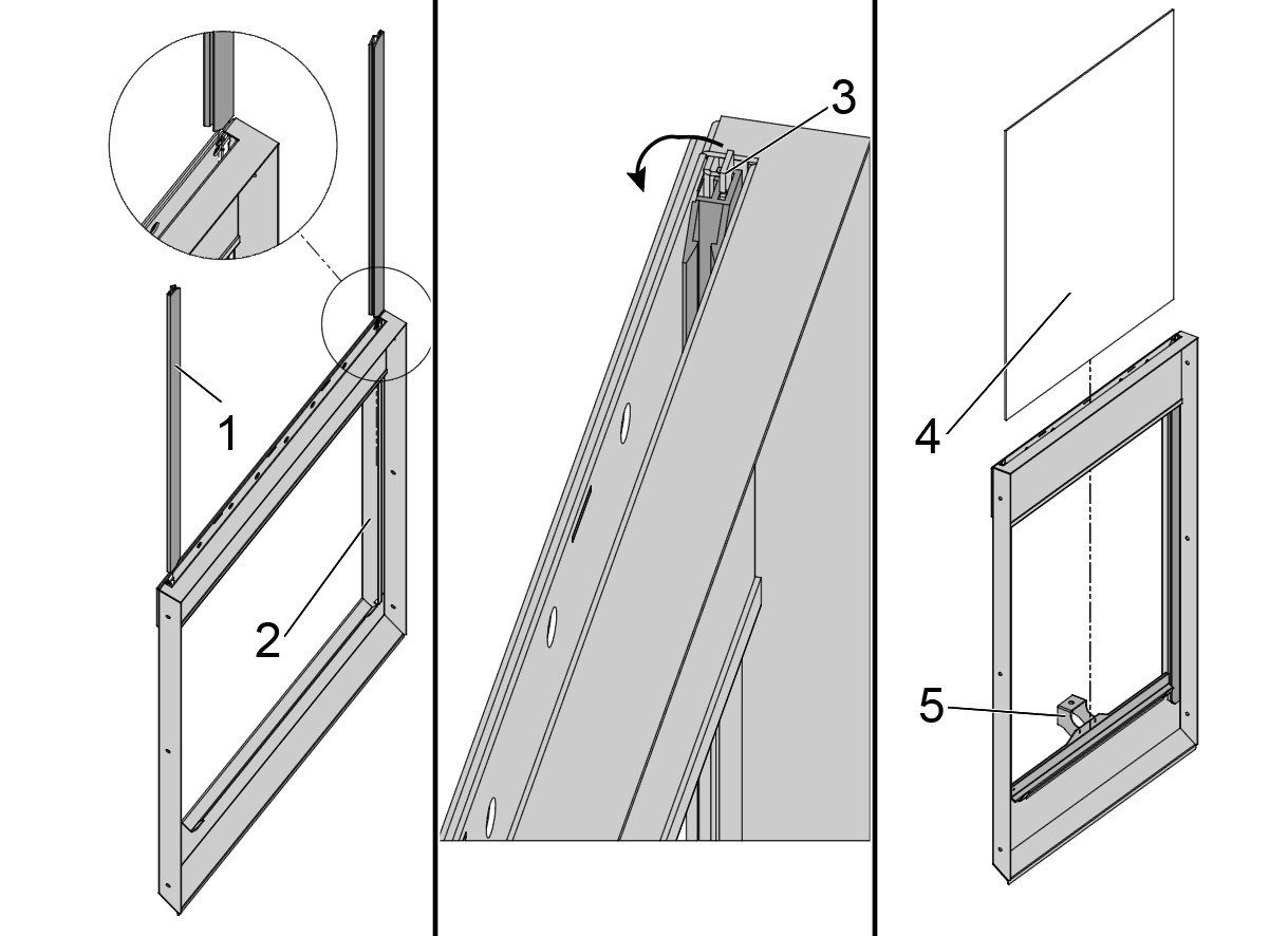
  • Gene Haas Foundation
  • Haas Technical Education Community
  • Events
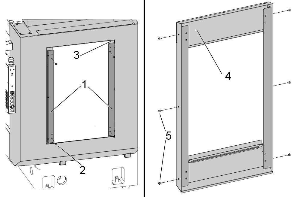
  • Join the Conversation
  • Facebook
  • X
  • Flickr
  • YouTube
  • LinkedIn
  • Instagram
  • TikTok
© 2026 Haas Automation, Inc – CNC Machine Tools
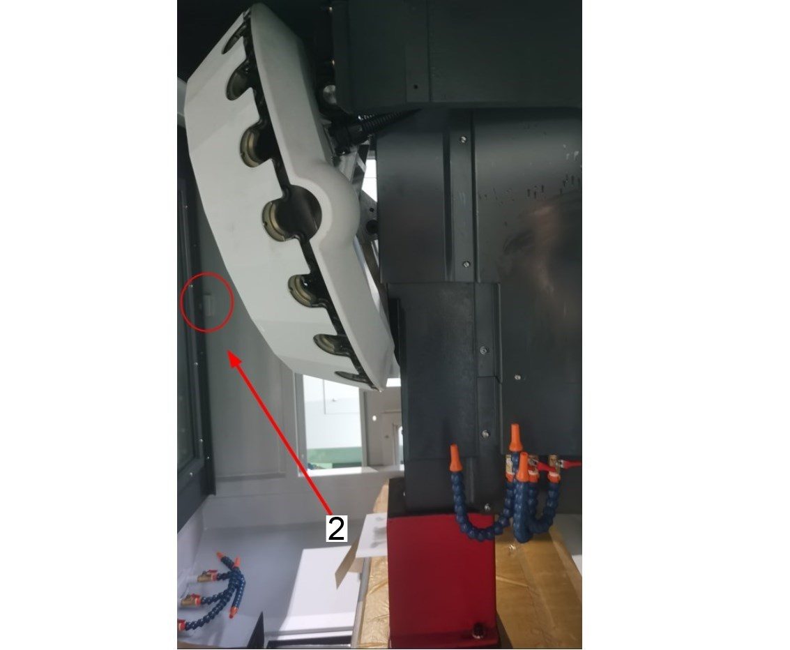
This site is protected by reCAPTCHA and the Google Privacy Policy and Terms of Service apply.

2800 Sturgis Rd., Oxnard, CA 93030
Toll Free: (888) 817-4446 / Fax: 805-278-8554