MyHaas Welcome,
!
Haas Tooling Guest Order History MyHaas/HaasConnect Sign In Register Haas Tooling My Account Order History Return History MyHaas/HaasConnect Sign Out Welcome, My Machines Latest Activity My Quotes My Account My Users Sign Out
Find Your Distributor
  1. Select Language
    1. English
    2. Deutsch
    3. Español - España
    4. Español - México
    5. Français
    6. Italiano
    7. Português
    8. Český
    9. Dansk
    10. Nederlands
    11. Magyar
    12. Polski
    13. Svenska
    14. Türkçe
    15. 中文
    16. Suomi
    17. Norsk
    18. الإنجليزية
    19. български
    20. Hrvatski
    21. Ελληνικά
    22. Română
    23. Slovenský
    24. Slovenščina
    25. 한국어
    26. 日本語
    27. Українська
  • machines Main Menu
    • Haas Vertical Mills Vertical Mills
      Vertical Mills
      Vertical Mills View All
      • Vertical Mills
      • VF Series
      • Universal Machines
      • VR Series
      • VP-5 Prismatic
      • Pallet-Changing VMCs
      • Mini Mills
      • Mold Machines
      • High-Speed Drill Centers
      • Drill/Tap/ Mill Series
      • Toolroom Mills
      • Compact Mills
      • Gantry Series
      • SR Sheet Routers
      • Extra-Large VMC
      • Double-Column Mills
      • Control Simulator
      • Mill Automatic Parts Loader
      • VMC/UMC Side-Loading Automatic Parts Loader
      • Compact Automatic Parts Loader
    • Product Image Multi-Axis Solutions
      Multi-Axis Solutions
      Multi-Axis Solutions View All
      • Multi-Axis Solutions
      • Y-Axis Lathes
      • 5-Axis Mills
    • Haas Lathes Lathes
      Lathes
      Lathes View All
      • Lathes
      • ST Series
      • Dual-Spindle
      • Box Way Series
      • Toolroom Lathes
      • Chucker Lathe
      • Haas Bar Feeder V2
      • Lathe Automatic Parts Loader
    • Haas Horizontal Mills Horizontal Mills
      Horizontal Mills
      Horizontal Mills View All
      • Horizontal Mills
      • 50-Taper
      • 40-Taper
    • Haas Rotaries & Indexers Rotaries & Indexers
      Rotaries & Indexers
      Rotaries & Indexers View All
      • Rotaries & Indexers
      • Rotary Tables
      • Indexers
      • 5-Axis Rotaries
      • Extra-Large Rotaries
    • Special Series
      Special Series
      Special Series View All
      • Special Series
      • EU_Series_Redirect
    • Product Image Automation Systems
      Automation Systems
      Automation Systems View All
      • Automation Systems
      • Mill Automation
      • Lathe Automation
      • Automation Models
    • Haas Drill Centers Desktop Machines
      Desktop Machines
      Desktop Machines View All
      • Desktop Machines
      • Desktop Mill
      • Desktop Lathe
    • Haas Shop Equipment Shop Equipment
      Shop Equipment
      Shop Equipment View All
      • Shop Equipment
      • Bandsaw
      • Knee Mill
      • Surface Grinder, 2550
      • Surface Grinder, 3063
      • Laser Cutting Machine
    • QUICK LINKS Special Series  Special Series 
      EU SERIES EU SERIES BUILD & PRICE | PRICE LIST BUILD & PRICE | PRICE LIST In-Stock Machines In-Stock Machines WHAT’S NEW WHAT’S NEW YOUR FIRST CNC YOUR FIRST CNC
      SHOPPING TOOLS
      • Build & Price a Haas
      • Price List
      • Available Inventory
      • CNCA Financing
      WANT TO TALK TO SOMEONE?

      A Haas Factory Outlet (HFO) can answer your questions, and walk you through your best options.

      CONTACT YOUR DISTRIBUTOR >
  • Options Main Menu
    • Product Image Spindles
      Spindles
      Spindles View All
      • Spindles
    • Product Image Tool Changers
      Tool Changers
      Tool Changers View All
      • Tool Changers
    • Product Image 4th- | 5th-Axis
      4th- | 5th-Axis
      4th- | 5th-Axis View All
      • 4th- | 5th-Axis
    • Product Image Turrets & Live Tooling
      Turrets & Live Tooling
      Turrets & Live Tooling View All
      • Turrets & Live Tooling
    • Product Image Probing
      Probing
      Probing View All
      • Probing
    • Haas Chip & Coolant Management Chip & Coolant Management
      Chip & Coolant Management
      Chip & Coolant Management View All
      • Chip & Coolant Management
    • The Haas Control The Haas Control
      The Haas Control
      The Haas Control View All
      • The Haas Control
    • Product Image Product Options
      Product Options
      Product Options View All
      • Product Options
    • Product Image Tooling & Fixturing
      Tooling & Fixturing
      Tooling & Fixturing View All
      • Tooling & Fixturing
    • Product Image Workholding
      Workholding
      Workholding View All
      • Workholding
    • Product Image 5-Axis Solutions
      5-Axis Solutions
      5-Axis Solutions View All
      • 5-Axis Solutions
      • 5 Easy Steps to 5-Axis
    • QUICK LINKS Special Series  Special Series 
      EU SERIES EU SERIES BUILD & PRICE | PRICE LIST BUILD & PRICE | PRICE LIST In-Stock Machines In-Stock Machines WHAT’S NEW WHAT’S NEW YOUR FIRST CNC YOUR FIRST CNC
      SHOPPING TOOLS
      • Build & Price a Haas
      • Price List
      • Available Inventory
      • CNCA Financing
      WANT TO TALK TO SOMEONE?

      A Haas Factory Outlet (HFO) can answer your questions, and walk you through your best options.

      CONTACT YOUR DISTRIBUTOR >
  • Why Haas Main Menu
      Discover the Haas Difference
    • Why Haas
    • MyHaas
    • Education Community
    • Industry 4.0
    • Haas Certification
    • Customer Testimonials
  • Service Main Menu
      Welcome to Haas Service
      SERVICE HOME Operator’s Manuals How-To Procedures Troubleshooting Guides Preventive Maintenance Haas Parts Haas Tooling Videos
  • Videos Main Menu
  • Main Menu
    • View All
    • View All
      • Fiber Laser
    • View All
    • View All
      • HTEC Curriculum Support
    • View All
      • Haas 10 kg Cobot Package
      • Cobot Kits
    • View All
    • View All
      • 4 - AUTOMATION SYSTEMS
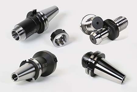
      • Mill Toolholding
      • Carousel-V2
    • View All
    • View All
    • View All
      • VF-4SS
    • View All
    • QUICK LINKS Special Series  Special Series 
      EU SERIES EU SERIES BUILD & PRICE | PRICE LIST BUILD & PRICE | PRICE LIST In-Stock Machines In-Stock Machines WHAT’S NEW WHAT’S NEW YOUR FIRST CNC YOUR FIRST CNC
      SHOPPING TOOLS
      • Build & Price a Haas
      • Price List
      • Available Inventory
      • CNCA Financing
      WANT TO TALK TO SOMEONE?

      A Haas Factory Outlet (HFO) can answer your questions, and walk you through your best options.

      CONTACT YOUR DISTRIBUTOR >
  • Haas Tooling Main Menu
      Automation Accessories Shop Support Mill Toolholding Mill Cutting Tools Boring Systems Mill Workholding Lathe Toolholding Lathe Cutting Tools Lathe Workholding Package Kits ER Collets & Chucks Holemaking Threading Broaching Tombstones & Kits Manual Chucks For Milling Deburring & Abrasives Tool Presetter & Heat Shrinkers Storage & Handling Machine Maintenance Tooling Accessories Apparel & Accessories Measuring & Inspection Winner's Circle Winner's Circle Clearance Today's Hot Deals
    • Haas Tooling
    • Winner's Circle
      Winner's Circle Shop All
      • WINNERS_CIRCLE-1Y
    • Winner's Circle
      Winner's Circle Shop All
      • WC-1Y-EU
    • Today’s Hot Deals
      Today’s Hot Deals Shop All
      • Mill Toolholding
      • Mill Tooling
      • Measuring & Inspection
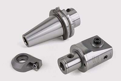
      • Boring Systems
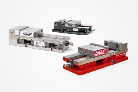
      • Mill Workholding
      • Shell Mill Kits
      • Lathe Toolholding
      • Lathe Tooling
      • Lathe Workholding
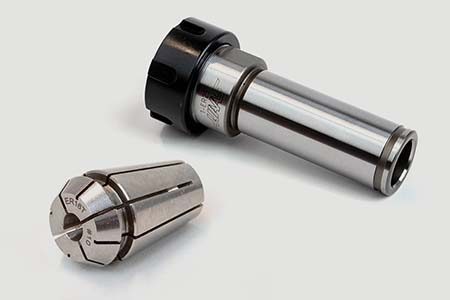
      • ER Collets & Chucks
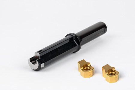
      • Holemaking
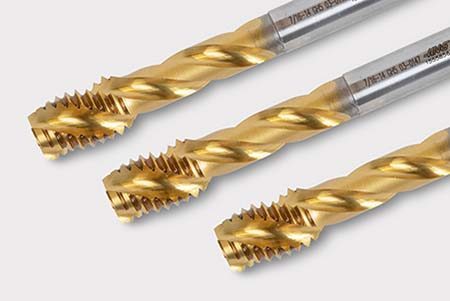
      • Threading
      • Broaching
      • Tool Storage
      • Apparel & Accessories
    • Clearance
      Clearance Shop All
    • Measuring & Inspection
      Measuring & Inspection Shop All
      • Probe Kits & Accessories
      • Edge & Center Finders
      • Comparative Measuring Gauges
      • Height Gauges
      • Calipers
      • Threaded Plug & Ring Gauges
      • Gauge Blocks
      • Pin Gauges
      • Drop Indicators
      • Dial Test Indicators
      • Bore Gauges
      • Indicator Accessories
      • V Blocks
      • Setup Blocks
      • Depth Measuring
      • Micrometers
      • Micrometer Accessories
      • Micrometer Kits
      • Bore Gauge Kits
      • Starter Kits
      • Indicator Kits
      • Caliper Kits
      • Toolholder Check Station
      • Height Setters
      • Coordinate Measuring Machines
    • Automation Accessories
      Automation Accessories Shop All
      • Cobot Kits
      • Cobot Kits
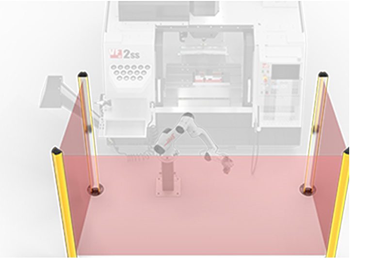
      • Protective Barriers
      • Grippers
      • Robot Cell Accessories
    • Shop Support
      Shop Support Shop All
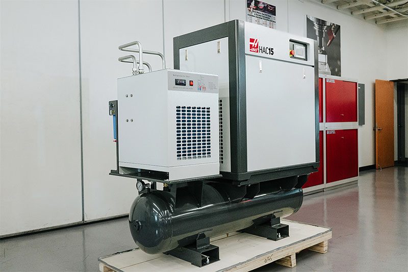
      • Air Compressors
      • Laser Marking Machines
      • Bandsaw Blades
      • Bandsaw Accessories
      • Surface Grinding Wheels
      • Shop Equipment Accessories
    • Mill Toolholding
      Mill Toolholding Shop All
      • End Mill Holders
      • Shell Mill Holders
      • Shrink Fit Holders
      • ER Collet Chucks
      • Milling Chucks & Collets
      • NC Drilling Chucks
      • Pull Studs / Retention Knobs
      • Rotary Tool Holder & Tool Chuck Kits
      • Hydraulic Milling Chucks & Collets
      • Toolholder Attachments & Wrenches
      • Mill Broaching Holders
    • Mill Tooling
      Mill Tooling Shop All
      • Shell Mill Bodies
      • Milling Inserts
      • End Mills
      • Chamfer Mills & Inserts
      • Indexable End Mill Bodies
      • Ball End Mills
      • Chamfer End Mills
      • Roughing End Mills
      • Indexable Ball End Mills & Inserts
      • Shell Mill Kits
      • Chamfer Mill Kits
      • Indexable End Mill Kits
      • Dovetail Cutters
      • Indexable Dovetail Cutters
      • Engraving End Mills
      • Rotary Burrs / Die Grinding Bits
      • Keyseat Cutters
      • Corner Rounding End Mills
      • Slot Mill Bodies
      • CNC Router Bits For Wood
    • Boring Systems
      Boring Systems Shop All
      • Boring Heads & Cartridges
      • Boring Holders & Extensions
    • Mill Workholding
      Mill Workholding Shop All
      • Fixed-Jaw Vises
      • Self-Centering Vises
      • Adapter Plates
      • Vise Jaws
      • Vise Mounts & Fixtures
      • Vise Kits
      • Vise Parallels
      • Rotary Vise Kits
      • Fixture Clamps & Rails
      • Automated Workholding Kits
      • Tooling Fixture Subplates
      • Toolmakers' Vises
      • Clamp Force Gauges
      • Collet Fixtures
      • Angle Plates
    • Lathe Toolholding
      Lathe Toolholding Shop All
      • TL & CL Static Turning Holders
      • BOT Static Turning Holders
      • BMT Static Turning Holders
      • Live / Driven Turning Holders
      • Turning Holder Reduction Sleeves / Bushings
      • VDI Static Turning Holders
      • Turning Holder Accessories
    • Lathe Tooling
      Lathe Tooling Shop All
      • Cut-Off Tool Blocks & Blades
      • Cut-Off Tooling Kits
      • Turning Inserts
      • Grooving & Cut-Off Tools
      • Internal (ID) Grooving & Threading Tools
      • Threading Inserts
      • Threading Tools
      • Boring Bars / Internal (ID) Turning Tools
      • External (OD) Turning Tools
      • Cermet Turning Inserts
      • CBN Turning Inserts
      • Haas Notch Grooving & Threading Inserts
      • Haas Notch Grooving & Threading Tools
      • Micro Turning Tools
      • Desktop Lathe Tools
    • Lathe Workholding
      Lathe Workholding Shop All
      • Live Centers
      • Spindle Reduction Sleeves / Liners
      • Quick-Change Collets
      • Quick-Change Collet Chucks
      • 5C Collets
      • 5C Collet Sets
      • Lathe Jaw Boring Rings
      • Lathe Jaws
      • Bar Pullers
      • Scroll Chucks
      • Guide Pins
      • Collet Accessories
    • Package Kits
      Package Kits Shop All
      • Chip Clearing Fan Kits
      • Cutting Tool Kits
      • Indexable End Mill Kits
      • Cut-Off Tool Block & Blade Kits
      • Drill & Tap Kits
      • Indexable Drilling Kits
      • Shell Mill Kits
      • Chamfer Mill Kits
      • Rotary Tool Holder & Tool Chuck Kits
      • Lathe Starter Kits
      • Workholding Kits
      • Rotary Vise Kits
      • Vise Kits
      • 3-Jaw Chuck Kits for Mills
      • Tombstone Kits
      • Reduction Sleeve Kits
      • Automated Workholding Kits
      • Measuring & Inspection Kits
      • Starter Kits
      • Bore Gauge Kits
      • Caliper Kits
      • Indicator Kits
      • Micrometer Kits
    • ER Collets & Chucks
      ER Collets & Chucks Shop All
      • ER Straight-Bore Collets
      • ER Sealed Collets
      • ER Tap Collets
      • ER Collet Sets & Accessories
      • ER Collet Chucks
      • Straight Shank ER Collet Chucks
      • Straight Shank Keyless NC Drilling Chucks
    • Holemaking
      Holemaking Shop All
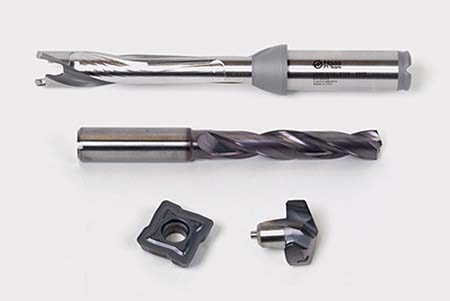
      • Carbide Drills
      • Indexable Drill Bodies
      • Indexable Drill Inserts
      • Modular Drill Bodies
      • Modular Drill Heads
      • Cobalt Drills & Sets
      • Center Drills
      • Reamers
      • Indexable Drilling Kits
      • Spot Drills
      • Spade Drill Bodies
      • Spade Drill Inserts
      • Countersinks
    • Threading
      Threading Shop All
      • Taps
      • Threading Inserts
      • Threading Tools
      • Thread Mills
      • Pipe Taps
      • Drill Tap Kits
    • Broaching
      Broaching Shop All
      • Broaching Tools
      • Broaching Inserts
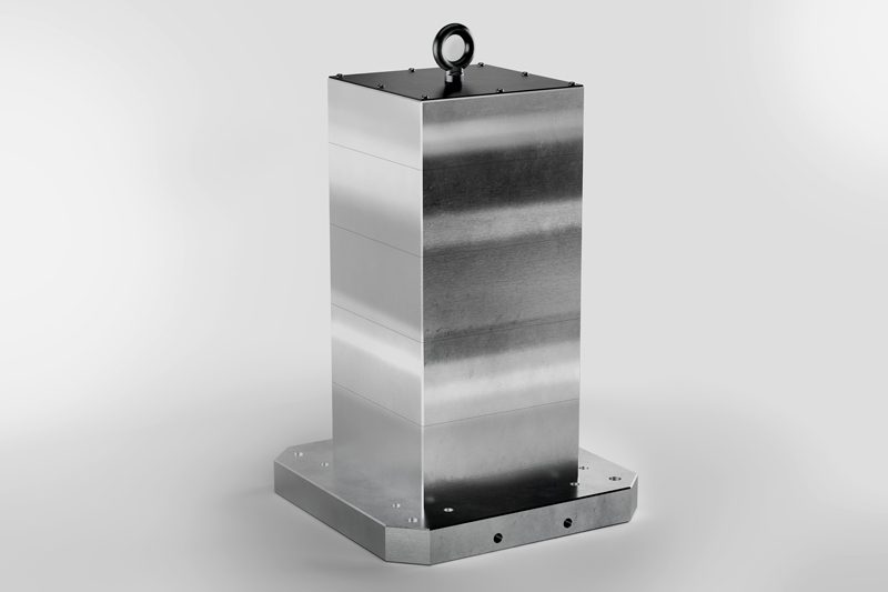
    • Tombstones
      Tombstones Shop All
      • Tombstones
      • Tombstone Kits
      • Vise Cluster Towers
    • Manual Chucks For Milling
      Manual Chucks For Milling Shop All
      • 3-Jaw Chucks & Mounts for Mills
    • Deburring & Abrasives
      Deburring & Abrasives Shop All
      • Abrasive Pads
      • Deburr Tools
      • Deburr Wheels
      • Abrasive Sheets & Rolls
      • Sharpening / Lapping Stones
    • Tool Presetter & Heat Shrinkers
      Tool Presetter & Heat Shrinkers Shop All
      • Tool Presetting Machines
      • Shrink Fit Machines
    • Tool Storage
      Tool Storage Shop All
      • Tool Carts
      • Tool Tray
      • Tool Bags
    • Machine Maintenance
      Machine Maintenance Shop All
      • Spindle Test Bars
      • Levels
      • Refractometers
      • Machine Additives & Supplies
      • Machine Accessories
      • Machine Maintenance Kits
    • Tooling Accessories
      Tooling Accessories Shop All

      • Spindle & Toolholder Taper Cleaners
      • Haas Shop Lift
      • Toolholder Fixtures
      • CNC Chip Clearing Fans
      • Hammers & Mallets
      • Anti-Fatigue Mats
      • Layout Tools
      • Wrenches
      • Magnetic Tools
      • Torque Screwdrivers
      • Hand Cutting Tools
      • Shop Stools
      • Lifting Magnets
      • Safety Apparel
      • Cutting Tool Sharpeners
    • Apparel & Accessories
      Apparel & Accessories Shop All
      • Accessories
      • Apparel
    • HAAS TOOLING QUICK LINKS
      NEW PRODUCTS NEW PRODUCTS NEW PRODUCTS NEW PRODUCTS
      MOST POPULAR MOST POPULAR
      TOOLING PROMOS TOOLING PROMOS
      FINANCING & OPEN TERMS FINANCING & OPEN TERMS PAY BY INVOICE PAY BY INVOICE
      FAQs FAQs
      KITS CREATED FOR YOU KITS CREATED FOR YOU
  • Haas Service Parts Main Menu
      Automatic Pallet Changer Lathe Turret Tool Changer Chip Management Coolant Counterbalance Electrical Cabinet Enclosure Hydraulics Lubrication Maintenance Pendant Probing Rotary Spindle Tailstock
    • Haas Service Parts
    • Automatic Pallet Changer
      Automatic Pallet Changer Shop All
      • HMC - Automatic Pallet Changer
      • VMC - Automatic Pallet Changer
    • Lathe Turret
      Lathe Turret Shop All
      • Lathe - Turret
      • Live Tooling
    • Tool Changer
      Tool Changer Shop All
      • Side Mount
      • Umbrella
    • Chip Management
      Chip Management Shop All
      • Multi Auger
      • Single Auger
    • Coolant
      Coolant Shop All
      • Auxiliary Filter
      • HPC-300 (Lathe)
      • HPC-1000 (Lathe)
      • Oil Skimmer
      • Standard Coolant
      • TSC-300 (Mill)
      • TSC-1000 (Mill)
      • Coolant Refill
      • Loc-Line
    • Counterbalance
      Counterbalance Shop All
      • Charge & Discharge Hose
    • Electrical Cabinet
      Electrical Cabinet Shop All
      • Fans
      • Filters
      • Upgrade Kits
    • Enclosure
      Enclosure Shop All
      • Accessories
      • Air Nozzle
      • Decals
      • Door Bumpers
      • Lighting
      • Windows, Gaskets, & Weather Strip
      • Chip & Coolant Management
    • Hydraulics
      Hydraulics Shop All
      • Filters
      • Gauges
      • Heat Exchanger
      • Hoses
    • Lubrication
      Lubrication Shop All
      • Bijur Mechanical Lubrication
      • Minimum Lubrication
    • Maintenance
      Maintenance Shop All
      • Grease, Oil, & Sealants
    • Pendant
      Pendant Shop All
      • Floppy Disk & USB
      • Keypad
      • Keys
      • Lens
      • Gaskets & Seals
    • Probing
      Probing Shop All
      • Mill Probing
      • Lathe Tool Presetter
    • Rotary
      Rotary Shop All
      • Rotary Gaskets & Seals
    • Spindles
      Spindles Shop All
      • Couplings
      • Gaskets & Seals
      • Spindle Motor Drive
      • Gearbox Drive
      • Tool Release Piston
    • Tailstock
      Tailstock Shop All
      • Handles
×

Search Results

Web Pages

Images

    • <
    • 1
    • >
MyHaas Welcome,
!
Haas Tooling Guest Order History MyHaas/HaasConnect Sign In Register Haas Tooling My Account Order History Return History MyHaas/HaasConnect Sign Out Welcome, My Machines Latest Activity My Quotes My Account My Users Sign Out
Find Your Distributor
  1. Select Language
    1. English
    2. Deutsch
    3. Español - España
    4. Español - México
    5. Français
    6. Italiano
    7. Português
    8. Český
    9. Dansk
    10. Nederlands
    11. Magyar
    12. Polski
    13. Svenska
    14. Türkçe
    15. 中文
    16. Suomi
    17. Norsk
    18. الإنجليزية
    19. български
    20. Hrvatski
    21. Ελληνικά
    22. Română
    23. Slovenský
    24. Slovenščina
    25. 한국어
    26. 日本語
    27. Українська
×

Search Results

Web Pages

Images

    • <
    • 1
    • >

Rotary - Installation - AD0005

Service Home How To Procedures Rotary - Installation - AD0005
Recently Updated Last updated: 12/15/2022

Rotary - Installation


AD0005

Rotary - Installation - AD0005

- Jump to Section - 1. Rotary - TR/TRT/T5C - Platter - Tool Change Offset - Adjustment 2. Rotary Removal 3. Rotary Troubleshooting 4. TRT - Probe Riser Block Back to Top

2.1 Lifting Instructions

Introduction

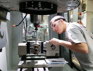
Use this procedure to install a Haas rotary product to a Haas CNC.  For connecting to a Haas Control box or other equipment, refer to the Rotary Operator's Manual that came with the unit or go to the Haas service page (www.haascnc.com) to download a copy.

Note: Rotary products can be installed in several ways. Use the following instructions as a guide.

Caution: The initial installation of this rotary must be done by a certified Haas Service Technician. Initial installation by non-certified personnel invalidates the warranty of the rotary.

The machine must have a fourth and or fifth axis drive installed for the rotary to operate.

Get the name and version of the rotary model from the rotary nameplate.

Tools Required:

  • Lifting Chain or Strap - The chain or strap must be rated for the weight of the rotary.
  • Spreader Beam - A spreader beam is recommended to keep the lifting chains vertical. It must be rated for the weight of the rotary. The width of the spreader beam must be the same as the width between the lifting eye bolts.
  • Lifting Device - A lifting device, such as a forklift, lifting hoist, etc., must be rated for the weight of the rotary.
  • Dial Indicator  - The dial indicator must be able to measure 0.0001” (0.003 mm)

Note: To find the weight of your rotary, go to www.haascnc.com. Search for your rotary. Select it from the list of results. The weight will be listed in the "Specifications" section.

Machine Compatibility

See the Rotary - Compatibility and servo motor configuration identification guide for information about rotary compatibility. 


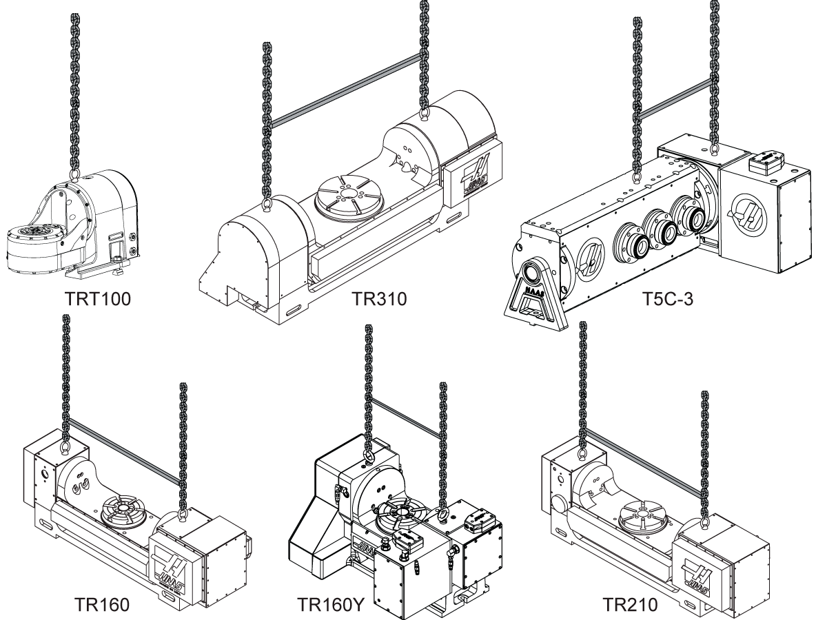
Rotary - TR/TRT/T5C - Lifting Instruction

Lift the rotary table with the lift rings as shown to prevent damage to the gear set. Attach an air supply to the rotary before you lift it. All rotary tables (HRT, TR, TRT, and T5C) use the 1/2-13 eyebolts. Haas Automation, Inc. does not supply lifting chains or straps for rotary products.

Warning: LIFTING A ROTARY WHILE NOT CONNECTED TO AIR MAY DAMAGE THE ROTARY. 

If spreader bars are not available, eyebolts may be used as shown:

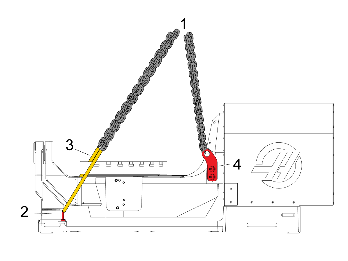
TR500SS

To lift the TR500SS, position your lifting mechanism above the center of gravity [1] to ensure the rotary is lifted uniformly.

Lift the machine from the eye bolts near the A frame [2] and the lifting bracket [4]. 

NOTE: Use straps [3] or something that won't damage the platter, as lifting it from this location will interfere with the platter.


TRT310 being lifted with two hooks. 

Lifting TRT 160 and TRT 210

There are two ways to lift the TRT160 and TRT210. 

1. Use the center hole on the top of the rotary. The center hole has 1/2-13 threads. Using this hole is similar to how the TRT100 is shown being lifted above. These two models will not come with the eye bolt for this hole. 

2. Use the two holes beside the center hole. The two holes on the side have M8-1.25 threads. These rotaries can be lifted similarly to how the TRT310 is lifted in the image. These units will come with the eyebolts that fit in these holes. These eye bolts have an ID of 0.75 inches (19 mm).


TRT 310

Unlike the two smaller rotaries, the TRT310 has no central hole that can be used for lifting. Also, these two side holes are larger than on the smaller models being 1/2-13 threads with the eyes having an ID of 1-1/8 inch. 

The TRT310 must be lifted using a sling with two hooks, as shown in the picture. A spreader bar is not needed. 

The TRT310 weighs about 1000 pounds. Verify that appropriate lifting equipment is ready for installation. 

2.2 Indexer Installation

Rotary - Indexers - Installation

HA5C Tooling Points

The HA5C is equipped with tooling points in order to speed setups. One of the most time-consuming procedures in setup is aligning the head with the table. On the mounting surfaces are two 0.500" bored holes on 3.000" centers.

The holes on the bottom surface are parallel to the spindle within 0.0005" per 6 inches and on center within ±0.001". By boring matching holes in the tooling plate, setups become routine. Using tooling holes also prevents the head from shifting on the mill table when the part is subjected to heavy cutting forces.

On CNC mills, a machined stepped plug of 0.500" diameter on one side and 0.625" on the other comes with the Haas head. The 0.625" diameter fits into the T-slot of the mill table, enabling quick parallel alignment.

1

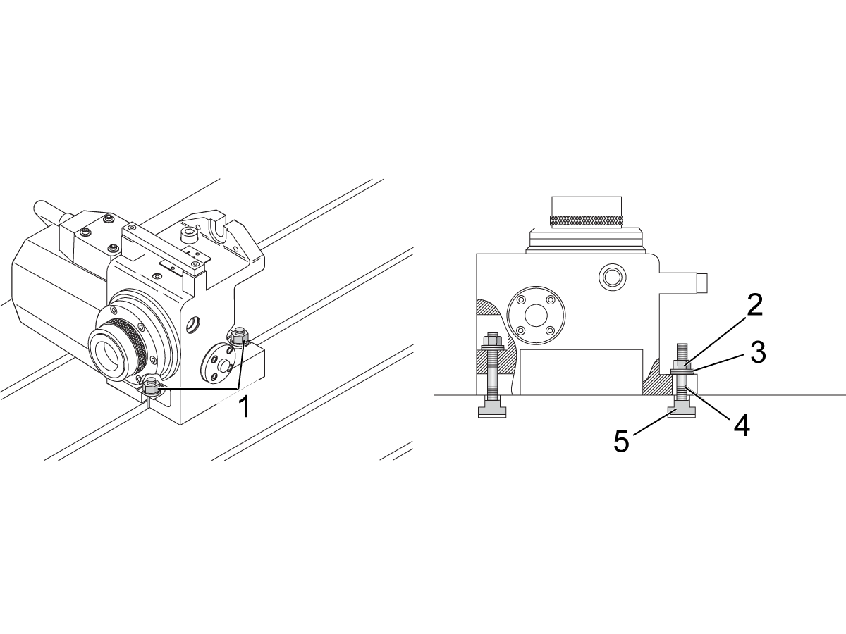
Upright Mounting (A or B axis Position): 

Install the T-Nuts on the machine table. If necessary, install the locating pins or alignment keys for your rotary.

 Note: To see if your rotary has locating pins or alignment keys refer to  Rotary - Locating Pins or Alignment Keys and find your rotary on the list.

Make sure the machine table and the bottom of the rotary are clean.

Put the rotary indexer on the table.

  •  Install the flange nuts, and Washers [1] on the front and back of the rotary to secure it to the table.
Back Mounting (C axis Position):
 
Put the rotary indexer on is back to the table.
  •  Install the flange nuts, and Washers [2,3,4,5] on the front and back of the rotary to secure it to the table.

2

Clean the machined surfaces of the rotary.

 Note: Use a pH-neutral degreaser. For example: WD-40, Sunnyside Odorless Mineral Spirits, or Benz Oil Sta-brite 306.

After the unit has been mounted and secured proceed to the Air and Electrical Connection section.

3

Once the rotary has been mounted and the electrical connections made to the machine the rotary needs to be enabled.

Instructions to enable Rotaries on NGC and CHC machines can be found at 2.6 Enable Rotary Axes.

Instructions to Initialize on rotary control boxes can be found at 4.1 Servo Control - Rotary Installation. 

2.3 HRT Installation

Rotary - HRT - Installation

1

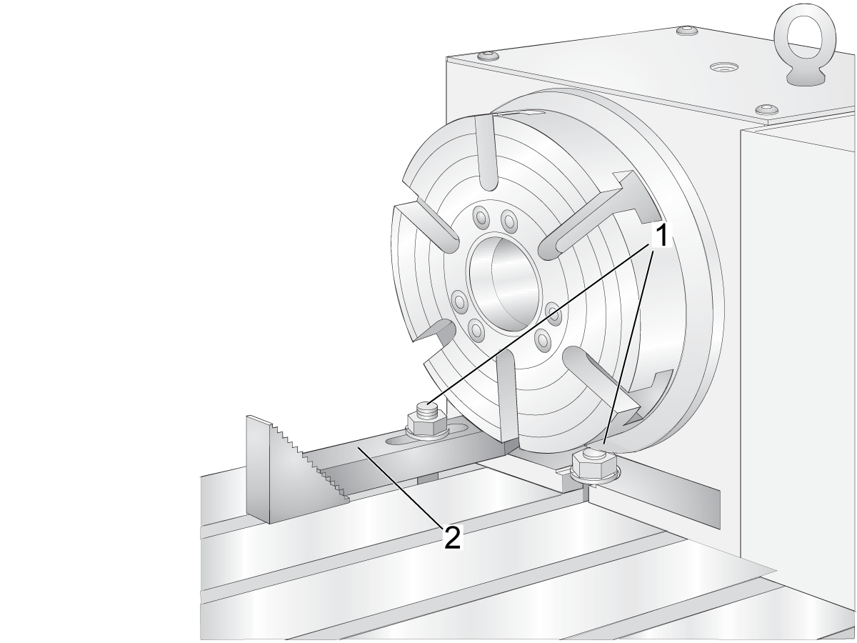
For upright mounting (A or B axis position):
 
Install the T-Nuts on the machine table. If necessary, install the locating pins or alignment keys for your rotary.
 
 Note: To see if your rotary has locating pins or alignment keys, refer to  Rotary - Locating Pins or Alignment Keys and find your rotary on the list.

Make sure the machine table and the bottom of the rotary are clean.

Use a lifting device to put the rotary on the table.

  •  Install the flange nuts and Washers [1] on the front and back of the rotary to secure it to the table.

Note: For extra rigidity, use additional Toe-Clamps [2] (*not supplied).


2

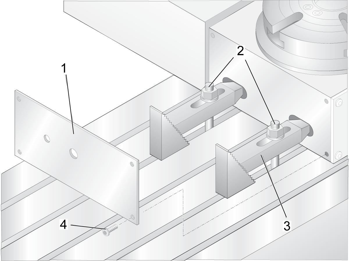
HRT Back Mounting (C axis position): 

Mount and secure the HRT 160, 210, 450, and 600 Rotary Tables as shown (except HRT 310).

Install the T-Nuts on the machine table.

Make sure the machine table and the bottom of the rotary are clean.

Use a lifting device to put the rotary on the table.

Remove the four 1/4-20 SHCS [4] to remove the Top Cover [1] to Access Toe-Clamp Pockets:

  • Use Toe-Clamp Assembly (2) to secure the rotary to the table.

Note: Only the HRT 310 and smaller can be installed on its back. Larger HRTs and all LTs must be installed vertically. 

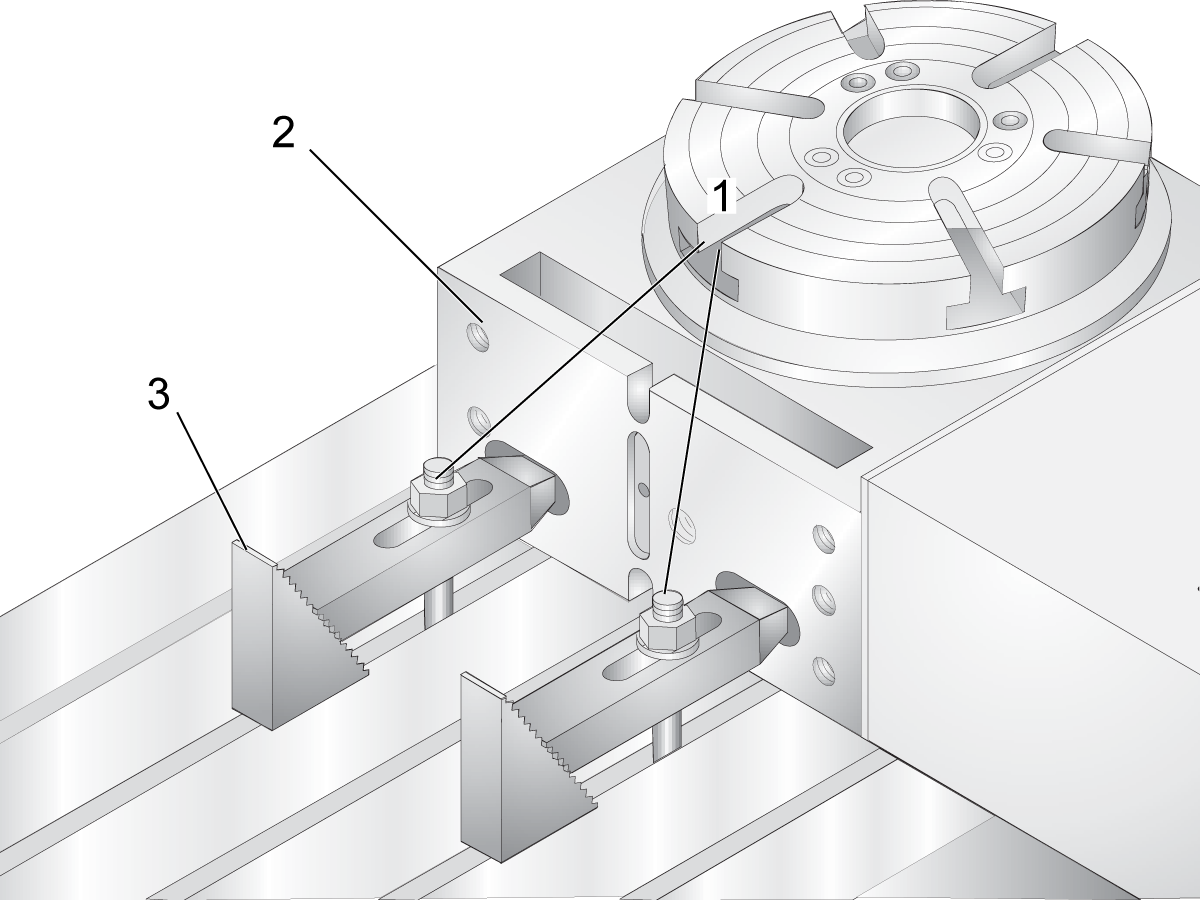
3

Secure the bottom of the casting [2] using toe clamps [1,3].

4

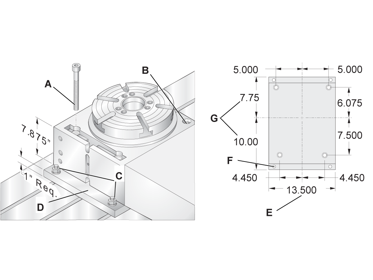
HRT 310 back mounting (C axis position). 

 Note: HRT310 units built during or after October 2019 will not have holes for mounting on their back. Drill 0.781 inch holes into the rotary body that line up with the threaded holes in the mounting plate. 

 Note: HRT310SS units will not have holes for mounting on their back for horizontal mounting. 

Machine a mounting plate as shown in the image to the left.

Make sure the machine table, the bottom of the rotary, and both sides of the mounting plate are clean. 

Use four T nuts to install the mounting plate into the machine.

Lift the HRT310 into the machine and bolt it to the mounting plate using four 3/4-10 x 8" bolts. 

5

Clean the machined surfaces of the rotary.

 Note: Use a pH-neutral degreaser. For example: WD-40, Sunnyside Odorless Mineral Spirits, or Benz Oil Sta-brite 306.

After the unit has been mounted and secured, proceed to the Air and Electrical Connection section.

6

Once the rotary has been mounted, and the electrical connections are made to the machine, the rotary needs to be enabled.

Instructions to enable Rotaries on NGC and CHC machines can be found at 2.6 Enable Rotary Axes.

Instructions to Initialize rotary control boxes can be found at 4.1 Servo Control - Rotary Installation. 

2.4 TR/TRT/T5C - Installation

Rotary - TR/TRT/T5C - Installation

1

Push [ZERO RETURN]. Push ALL.

Move the machine table [1] to the position nearest to the doors.

Push [EMERGENCY STOP].

Connect the rotary air hose to an air supply. The air pressure engages the brake on each rotary axis to prevent internal damage.

 Caution: Make sure the air hose has sufficient length to prevent damage to the rotary when you install it.

2

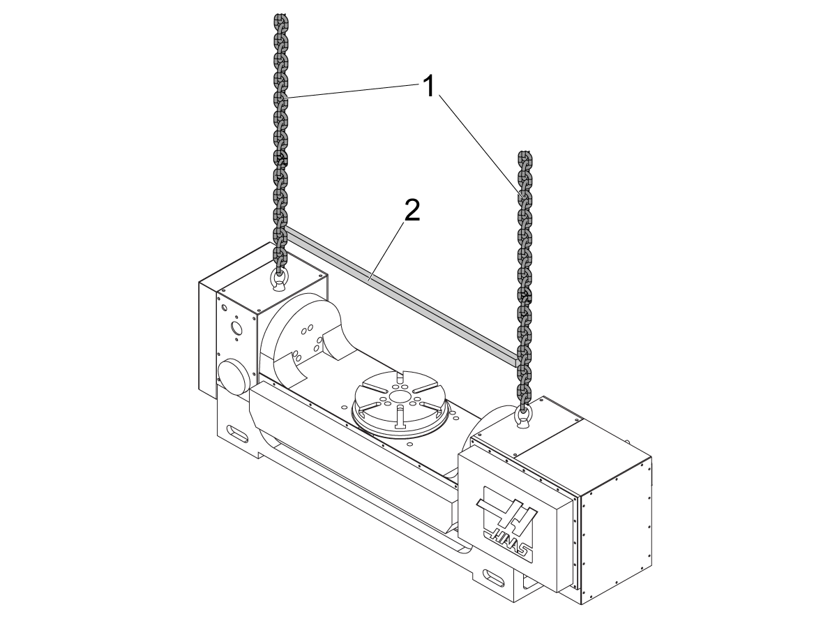
Install the eye bolts included with the rotary.

Install the lifting chains [1] and the spreader beam [2].

Refer to the "Rotary - TR/TRT/T5C – Lifting Instructions" at the end of the procedure for more information.

 Caution:

  • Use a spreader beam, chains, and the air hose connected to an air supply to prevent damage to the rotary.
  • Use a spreader beam to make sure the chains stay vertical.
  • Make sure the TILT Axis is flat to prevent damage to the rotary. If the TILT Axis is not flat, speak to your Haas Factory Outlet (HFO).

3

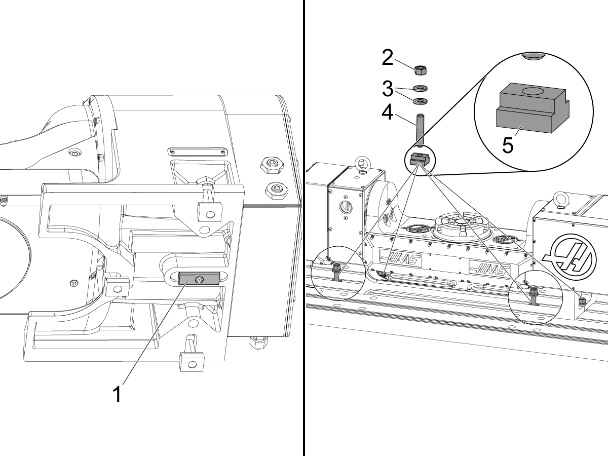
Install the T-Nuts [5] on the machine table. If necessary, install the locating pins or alignment keys [1] for your rotary.

 Note: To see if your rotary has locating pins or alignment keys refer to  Rotary - Locating Pins or Alignment Keys and find your rotary on the list.

Make sure the machine table and the bottom of the rotary are clean.

Use a lifting device, to put the rotary on the table.

 Caution: If necessary, get a second person to help carefully move the rotary into the machine.

Remove the eye bolts and the lifting chains or straps. Install (1) 1/2-13 double-threaded stud [4], (2) washers [3], and (1) nut [2] on each T-Nut. Use your hand to tighten the nut. This lets you make adjustments when you align the rotary.

 Note: For some rotaries, you must turn (“tilt”) the A Axis to install all of the double-threaded studs, washers, and nuts.

4

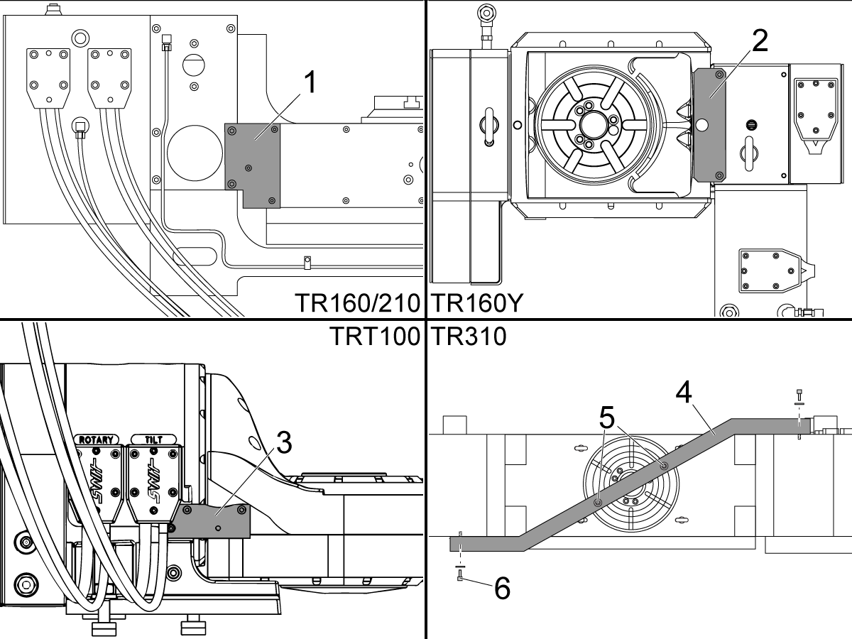
Remove the standoffs and the shipping brackets from these locations:

  • The right rear [1] of a TR160/210.
  • The top [2] of a TR160Y.
  • The rear center [3] of a TRT100.

 Note: T5C does not have a shipping brackets.

For a TR310, remove the (4) 1/2-13 screws and washers [5] and [6] from the shipping bracket [4]. Remove the (2) T-Nuts from the rotary platter.

 Note: Keep all of the hardware and the shipping brackets.

In the same location, install the screws that you removed from the shipping bracket. This prevents contamination from coolant in the rotary unit. Do not install the screws you removed from the platter.

5

Clean the machined surfaces of the rotary.

 Note: Use a pH-neutral degreaser. For example: WD-40, Sunnyside Odorless Mineral Spirits, or Benz Oil Sta-brite 306.

After the unit has been mounted and secure proceed to the Air and Electrical Connection section.

6

Once the rotary has been mounted and the electrical connections made to the machine the rotary needs to be enabled.

Instructions to enable Rotaries on NGC and CHC machines can be found at tab 2.6 Enable Rotary Axes.

Instructions to Initialize on rotary control boxes can be found 4.1 Servo Control - Rotary Installation. 

TRT - Probe Riser Block

Follow the link below for instructions on how to install the Probe Riser Block to a TRT.

TRT - Probe Riser Block - Installation

2.5 Air/Rotary Cable Connection

Introduction

1

This procedure will cover installing the rotary cable management kit, formerly the rotary retract kit. This kit keeps the conduit from rubbing on the way covers while jogging the mill.

Rotaries built after February 2022 that include rotary cable support either as a standard feature or an additional option will be shipped with the new style of cable management. 

Required Materials: 

  • Part number: ROTARY-CBL-SUPPORT.

Follow the link if you are looking for the ROTARY INSTALLATION PROCEDURE.

Follow this link if you are looking for the ROTARY TROUBLESHOOTING PROCEDURE.

WIPS Alarms:

  • Alarm 1101 PROBE STARTUP FAILURE 
  • Alarm 1092 UNEXPECTED SURFACE FOUND

If, after installing a rotary, you start getting either of the above alarms, the rotary, the retract kit, or the rotary cables may be the cause. These items may break the line of sight between the probe and the OMI or the Tool Setter and the OMI. 

To solve this problem, either move the cable retention kit so that the cables and spring don’t break the line sight or move the OMI to a location where the cables and spring will not be in the way. 

Installation

1

After the rotary is placed in the machine and secured to the table, have the machine zero return to home. 

Remove the zip ties and any other packaging on the rotary cables. 

Undo the two screws [1] holding the top part of the bracket [2]. Put the top part of the bracket to the side and route the rotary cables through the hole. Do not pull the cable tight, and be sure that the section of the cable in the enclosure has some slack. 

Note: The images in this procedure use the newest bracket. Machines from March 2022 and later will be compatible with this bracket. Older machines will need a different bracket with a different bolt pattern. 

 Warning: The next few steps may require getting fully in the machine. Be sure to take the proper lock-out tag-out precautions any time someone is in a machine. 

2

Place all the cables in the Rotary Cable support. This will require a 5/32 Allen wrench. The ribs in the clamp [1] are meant to fit into the ribs of the cable sleeve. This prevents the clamp from sliding up and down the rotary cable. 

Place the magnet and spring in such a way that there is some but very little slack in the cable. This extra slack will ensure that when the machine zero returns, it won’t pull on the cable or damage it. 

The large holes [2] are for the power cables. The medium side [3] holes below the large holes are for the scale cables. The smallest holes [4] are for the airlines.   

With the machine still in the front left and the retention spring installed, adjust the cable in, or out of the machine so there is a little slack between the clamp and the routing hole in the enclosure. 

3

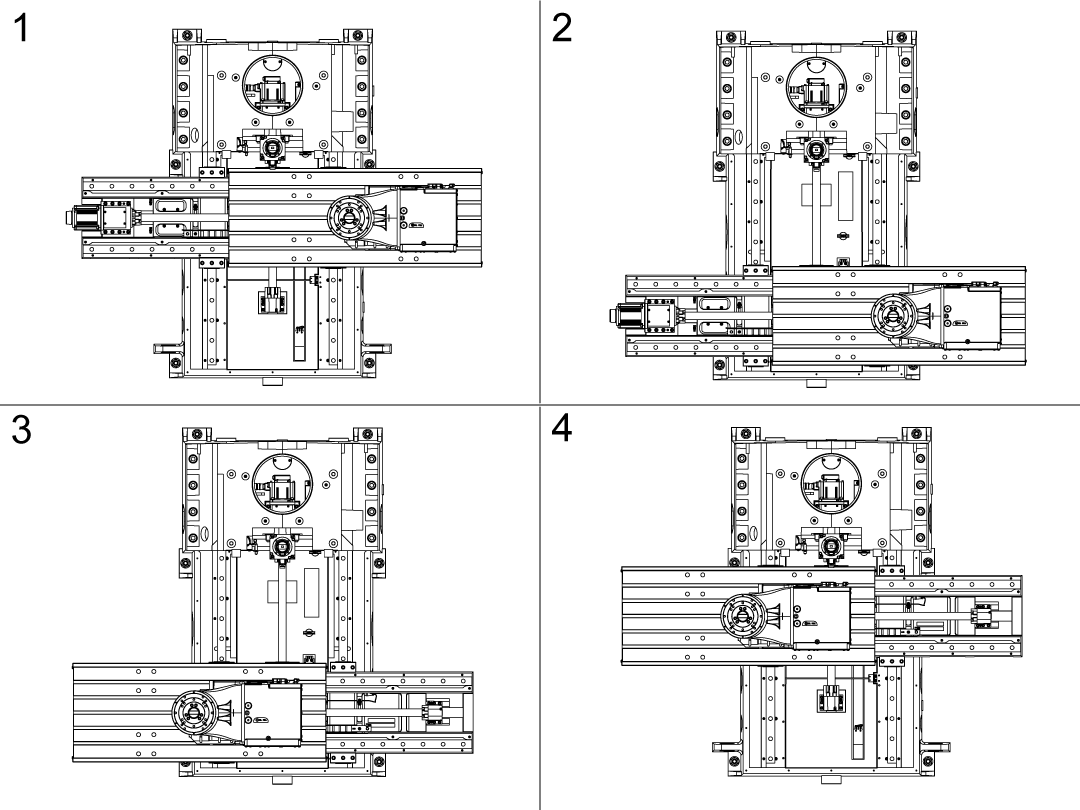
Once the cable support assembly has been installed, move the X & Y axis to max travel in the negative and positive directions following the image.

Ensure the Mill table can jog in all directions without the support spring and rotary cables getting in the way or getting damaged. 

Below are descriptions of how the cable should be routed in the machine. 

Note: In the images below, the magnet is shown as being placed on the back panel of the mill's enclosure. It can also be placed on the top panel of the enclosure. 

Warning: The Rotary cables should not be dragged through chips as this will damage the cable. 

Once you have verified that the cables will move safely, reinstall the top part of the cable bracket removed in step 1.  

4

Front Left

When the table is in the front left, the cables should be set up so that there is some tension and no slack between the cable clamp and the rotary, and there is some slack between the cable clamp and the cable routing hole in the enclosure. 

Since the home position is slightly more forward and to the left than the machine's zero position, the additional slack is necessary to pull on or damage the cable while zero returning the machine. 

 Note: It is best to keep the spring’s extension as small as possible. The more extended a spring is, the greater force it applies to the cable. This can be adjusted by loosening the clamp and moving it back several ribs on the cable sleeve or moving the magnet. 

5

Back Left

When the table is in the back left of the machine, there will still be no slack on the cable between the cable clamp and the rotary. The cable should be slightly drooping on the clamp's other side. 

6

Back Right

In the back right corner, only the weight of the cables will be pulling on the spring. 

It is best if the cable stays higher than the table, as this reduces the chance of the cable getting crushed. 

If you expect a large volume of chips in the machine, pay close attention if the cable will be dragging on chips. Regularly dragging on chips will eventually damage the cable and fail. 

7

Front Right

This corner is similar to the back right corner, but there is a bit less slack in the cable. 

8

Work Area

Test the mill’s movement in the expected work area as a final check. Since this is where the machine will be most of the time, it is best to verify that the cables are in a good position. 

If you intend to use WIPS for work probing, place a part on the rotary and probe it. If alarms 1101 or 1092 are generated, the cables, spring, or rotary may be getting in the way. 

Moving the retract kit magnet may move the cables and spring out of the way. If the rotary is in the way, moving the OMI or using a longer stylus may fix the issue. 

2.6 Enable Rotary Axes

Rotary - Enable

Do this procedure after you install a rotary unit. This procedure tells you how to tell the control what rotary unit you installed. Do this procedure on a machine that has the Next Generation Control. This rotary selection tool replaces Setting 30 and 78 used on CHC controls. See enable Rotary axis - CHC for instructions. 

1

Push [POWER ON].

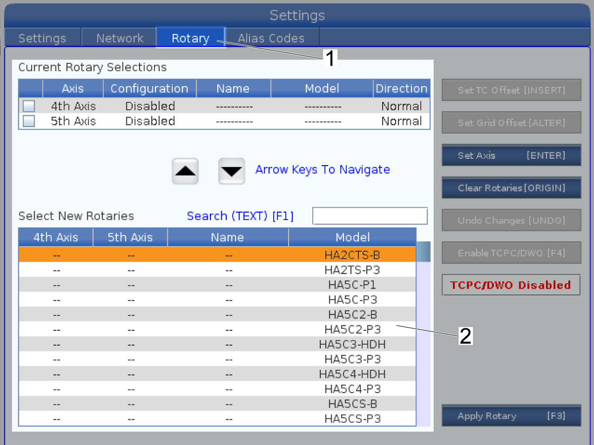
Push [SETTING].

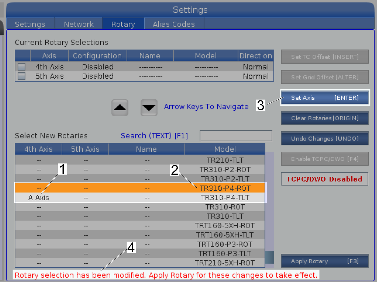
Select the Rotary tab [1].

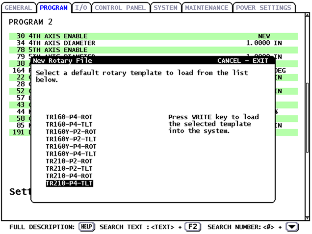
2

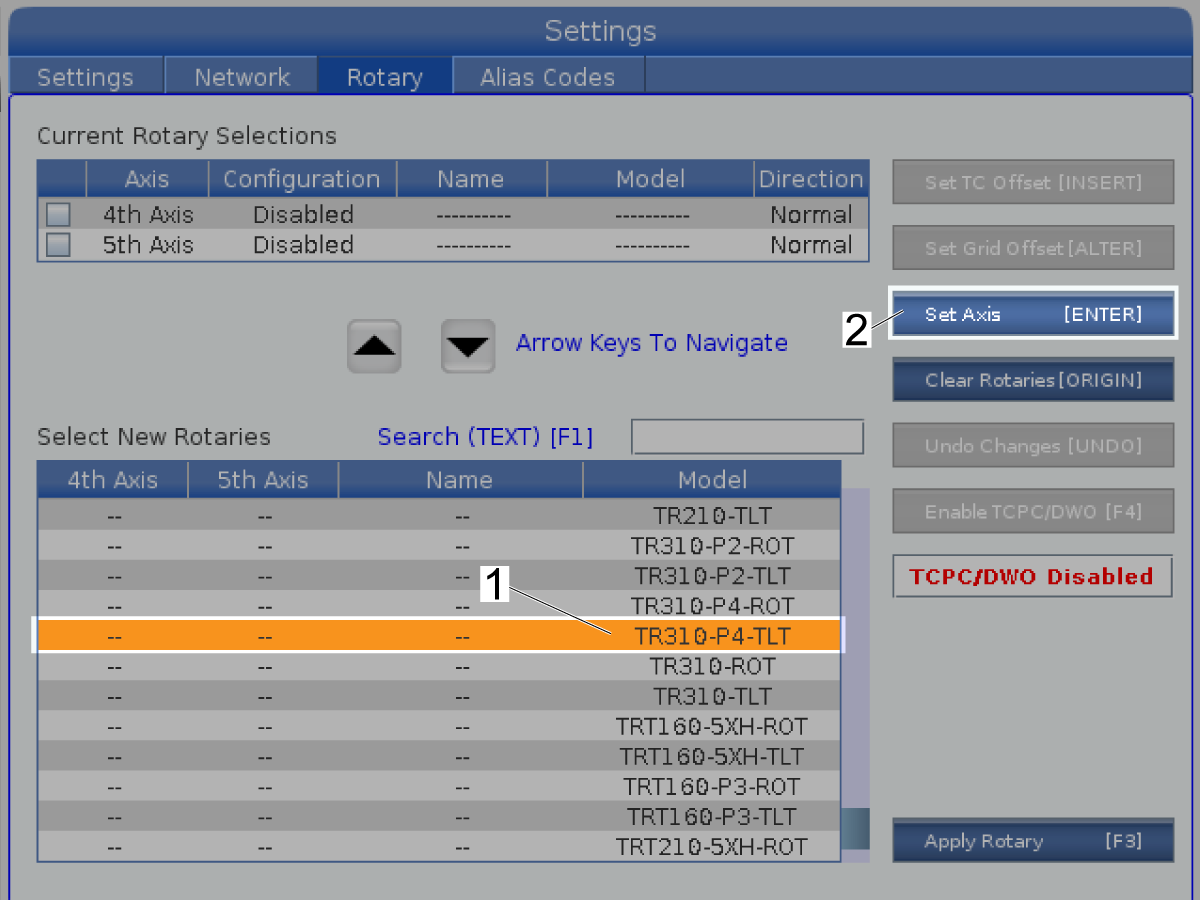
Highlight the 4th Axis rotary unit that is installed [1].

Push [ENTER] to Set Axis [2].

 Note: This screen shows the TR310-P4-TLT rotary.

Note:  If your rotary product does not appear in the list, the control may need to update the rotary configuration. Only Haas technicians can update configuration files. Contact your HFO to schedule the update and refer to the Update Rotary Configuration Files procedure.

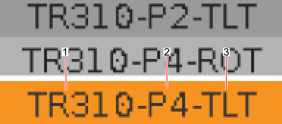
NOTE: CONFIG FILE NAME INFORMATION

Single axis rotaries require one config file, while dual axis requires two files. 

All config file names are broken up into several parts separated by dashes. 

The first part is the model number of the rotary unit [1]. This can be found on the serial plate of the unit. Some Rotary units have a dash in their name, that dash may or may not be included in the file name. 

The next part of the file name is the P version number of the unit [2]. This can also be found on the serial plate of the unit.  

The next part of the files only appears on dual axis Rotaries. The next part is either "TLT" or "ROT" [3]. TLT applies to the 4th axis, and ROT applies to the 5th axis. Single axis rotaries will not have this part.

The last part of the name is an R at the end. Using this configuration file would make the Rotary turn in the opposite direction.

3

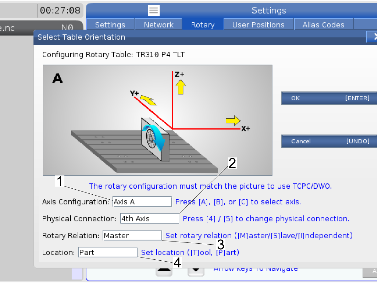
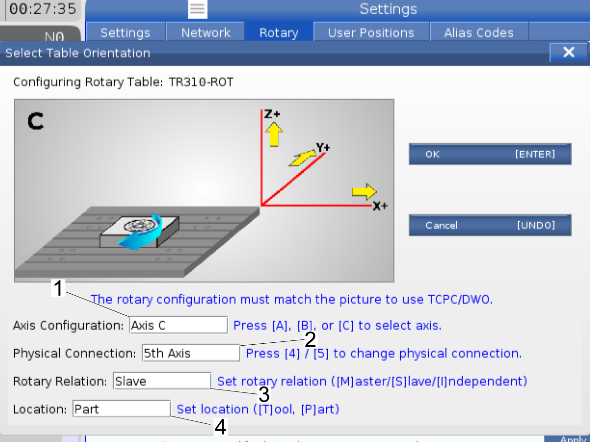
Push [A], [B], or [C] to select the Axis Configuration [1]. By default, the 4th axis is set to A. 

Push [4] / [5]  to change the physical connection [2].

Push [M] , [S] , [I] to select Rotary relation to change the physical connection [3]. 

Push [T] / [P]  to Set Loaction [2].

For this example, the Axis Configuration is Axis A [1], and the Physical Connection is the 4th axis [2].

 Note: To use the Tool Center Point Control (TCPC, G234) or Dynamic Work Offset (DWO, G254), make sure the position of the rotary unit is the same as the illustration on the display.

Push [ENTER].

4

This example sets the TR310-P4-TLT to the A Axis [1].

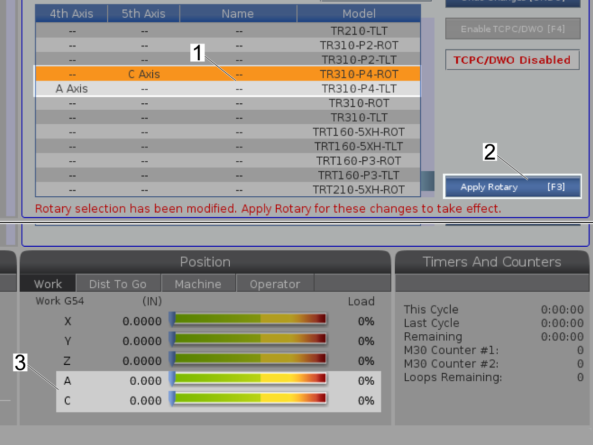
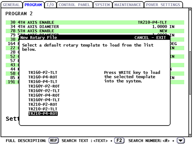
 Note: The rotary changes do not go into effect until you push [F3] (Apply Rotary) [4]. Go to Step 6 if you are ready to press [F3] (Apply Rotary).

Select the 5th Axis rotary unit that is installed [2].

Push [ENTER] to Set Axis [3].

 Note: This screen shows the TR310-P4-ROT rotary.

5

Push [A], [B], or [C] to select the Axis Configuration [1]. By default, the 4th axis is set to A. 

Push [4] / [5]  to change the physical connection [2].

Push [M] , [S] , [I] to select Rotary relation to change the physical connection [3]. 

Push [T] / [P]  to Set Loaction [2].

For this example, the Axis Configuration is Axis A [1], and the Physical Connection is the 4th axis [2].

 Note: To use the Tool Center Point Control (TCPC, G234) or Dynamic Work Offset (DWO, G254), make sure the position of the rotary unit is the same as the illustration on the display.

Push [ENTER].

6

This example sets the TR310-P4-TLT to the A Axis and set TR310-P4-ROT to the C Axis[1].

Then, push [EMERGENCY STOP].

Push [F3] to Apply Rotary [2].

Go to the next step to use TCPC or DWO if you do not use TCPC or DWO, power cycle the machine.

The A and C Axes are shown under Position [3].

7

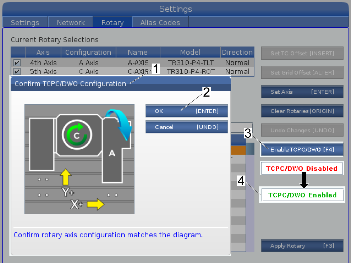
To use TCPC or DWO:

Push [F4] to Enable TCPC/DWO [3].

Confirm TCPC/DWO Configuration [1] shows in the display.

Ensure the rotary unit's position is the same as the illustration in the display.

Push [ENTER] [2] to confirm.

TCPC/DWO Disabled changes to TCPC/DWO Enabled [4].

Push [F3] to apply the Rotary.

Power cycle the machine.

8

Push [ZERO RETURN]. Start with the X Axis.

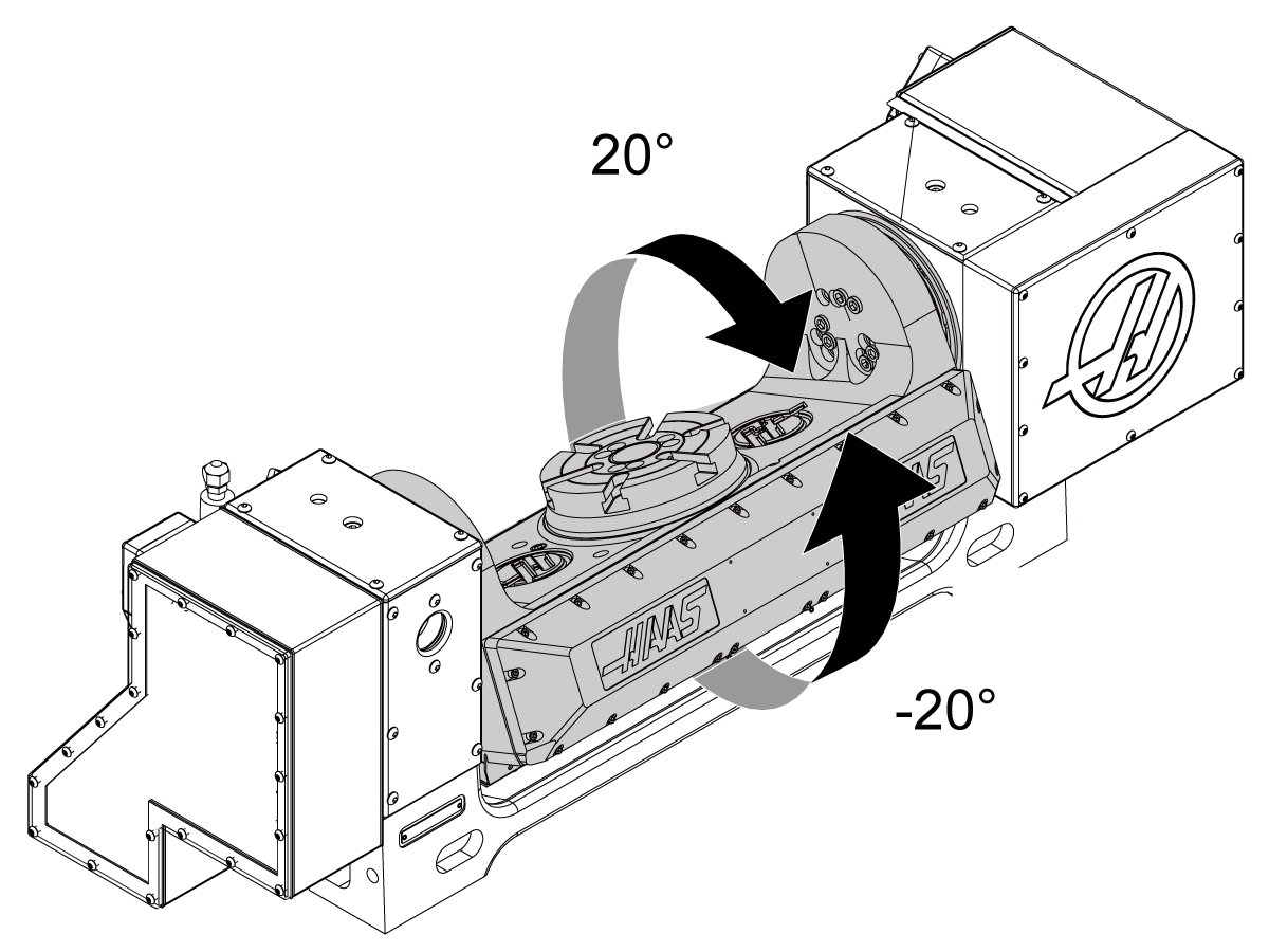
 Caution: If the A axis (tilt) moves more than 20 degrees past the home position,

Push [EMERGENCY STOP] to prevent damage. Ensure you selected the correct config file for your rotary model, 4TH AXIS ENABLE, and 5TH AXIS ENABLE.

Jog the machine table to the maximum travel in each axis.

 Caution: Ensure the cables do not get caught on the table or crushed between the table and the enclosure to prevent damage.

Rotate ("tilt") A axis to get access to the T-Nuts.

Then, push [EMERGENCY STOP].

Install the remaining studs, washers, and nuts.

9

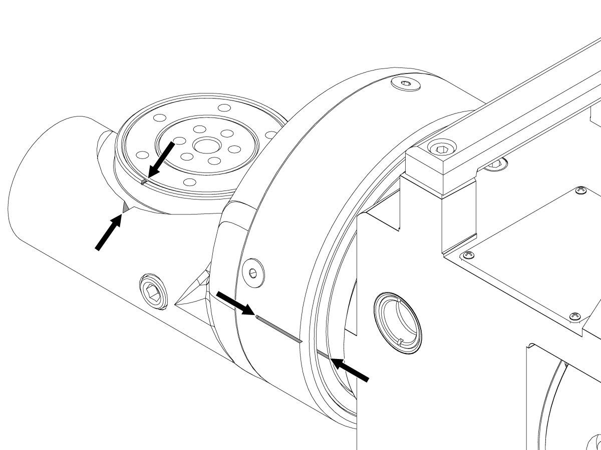
TRT70 Only:

Enable Setting 53 Jog W/O Zero Return.

Jog the A axis (tilt) until the slots are aligned as shown.

Jog the B axis (rotary) until the notches are aligned as shown.

Push [ZERO RETURN], [A].  Wait for the axis to find the home position.

Push [ZERO RETURN], [B].  Wait for the axis to find the home position.

 Caution: Make sure the cables do not get caught on the table or get crushed between the table and the enclosure to prevent damage.

Disable Setting 53 Jog W/O Zero Return.

Enable Rotary Axes - CHC

1

Before a Rotary is connected to a CHC machine the Rotary Compatibility Chart should be checked to see if the rotary is compatible with CHC machines. 

Note: Newly built Simga 5 rotaries need to be modified to be compatible with CHC machines. HSA - 5/14/2020

2

Go to Setting 7. Set the PARAMETER LOCK to OFF.

In PARAMETER 315 enable FOURTH AXIS and FIFTH AXIS. This requires a code that will be provided by the HFO. 

Change setting 30 4TH AXIS ENABLE to NEW.

Push [ENTER].

Select the correct rotary model and axis.

 Note: For example, if the nameplate is TR210 Ver. P4, select TR210-P4-TLT.

Push [ENTER].

 Note: On some machines, not all rotary models are available on setting 30 4TH AXIS ENABLE.

If your rotary model is not available, you must select USER1 for the A axis.

Use a parameter list to enter all the A-Axis parameters . If you do not have a parameter list, speak to your Haas Factory Outlet (HFO).

3

Change Setting 78 5TH AXIS ENABLE to NEW.

Push [ENTER].

Select the correct rotary model and axis.

 Note: For example, if the nameplate is TR210 Ver. P4, select TR210-P4-ROT.

Push [ENTER].

 Note: On some machines, not all rotary models are available on setting 78 5TH AXIS ENABLE.

If your rotary model is not available, you must select USER2 for the B axis.

Manually enter all the B axis parameters using a parameter list. If you do not have a parameter list, speak to your Haas Factory Outlet (HFO).

Push [POWER OFF].

Push [POWER ON].

Release [EMERGENCY STOP].

4

Push [ZERO RETURN]. Start with the X Axis.

 Caution: If the A axis (tilt) moves more than 20 degrees past the home position,

Push [EMERGENCY STOP] to prevent damage. Make sure that you selected the correct rotary model for setting 30, 4TH AXIS ENABLE and setting 78, 5TH AXIS ENABLE. If you selected the correct rotary model and axis, speak to your Haas Factory Outlet (HFO).

Jog the table to the maximum travel in each axis.

 Caution: Make sure the cables do not get caught on the table or get crushed between the table and the enclosure to prevent damage.

Turn ("tilt") A axis to get access to the T-Nuts.

Push [EMERGENCY STOP].

Install the remaining studs, washers and nuts.

5

TRT70 Only:

Enable Setting 53 Jog W/O Zero Return.

Jog the A axis (tilt) until the slots are aligned as shown.

Jog the B axis (rotary) until the notches are aligned as shown.

Push [ZERO RETURN], [A].  Wait for the axis to find the home position.

Push [ZERO RETURN], [B].  Wait for the axis to find the home position.

 Caution: Make sure the cables do not get caught on the table or get crushed between the table and the enclosure to prevent damage.

Disable Setting 53 Jog W/O Zero Return.

Rotary - TR/TRT/T5C - Platter - Tool Change Offset - Adjustment

Use the following procedure to set the Rotary - TR/TRT/T5C - Platter - Tool Change Offset.

Rotary Removal

To properly remove the rotary from the machine refer to the Rotary - Removal procedure.

Rotary Troubleshooting

Use the following links:

  • Rotary - Troubleshooting Guide - NGC  If you encounter any problems during the installation of the rotary on a Next Generation Control.
  • Rotary - Troubleshooting Guide - CHC  If you encounter any problems during the installation of the rotary on a Classic Haas Control.

TRT - Probe Riser Block

Follow the link below for instructions on how to install the Probe Riser Block to a TRT.

TRT - Probe Riser Block - Installation

Recently Viewed Items

You Have No Recently Viewed Items Yet

Feedback
Haas Logo

美元价格不包括关税、报关费用、保险费、增值税及运费。
USD prices DO NOT include customs duty, customs fees, insurance, VAT, or freight.

人民币价格包含关税、报关费用、货运保险和增值税, 但不包括运费。
CNY prices include customs duty, customs fees, insurance, and VAT. DOES NOT include freight.

Haas Delivered Price

This price includes shipping cost, export and import duties, insurance, and any other expenses incurred during shipping to a location in France agreed with you as a buyer. No other mandatory costs can be added to the delivery of a Haas CNC Product.

KEEP UP WITH THE LATEST HAAS TIPS AND TECHNOLOGY...

Sign up now!   

HAAS TOOLING ACCEPTS THE FOLLOWING:

  • Service & Support
  • Owners
  • Request Service
  • Operator Manuals
  • Haas Parts
  • Rotary Repair Request
  • Pre-Install Guides
  • Shopping Tools
  • Build & Price a New Haas
  • Available Inventory
  • The Haas Price List
  • CNCA Financing
  • About Haas
  • DNSH Statement
  • Careers
  • Certifications & Safety
  • Contact Us
  • History
  • Terms & Conditions
  • Haas Tooling Terms & Conditions
  • Privacy
  • Warranty
  • Haas Community
  • Haas Certification Program
  • Haas Motorsports
  • Gene Haas Foundation
  • Haas Technical Education Community
  • Events
  • Join the Conversation
  • Facebook
  • X
  • Flickr
  • YouTube
  • LinkedIn
  • Instagram
  • TikTok
© 2025 Haas Automation, Inc – CNC Machine Tools

This site is protected by reCAPTCHA and the Google Privacy Policy and Terms of Service apply.

2800 Sturgis Rd., Oxnard, CA 93030
Toll Free: (888) 817-4446 / Fax: 805-278-8554