My Haas Welcome,
!
Haas Tooling MyHaas/HaasConnect Sign In Register Haas Tooling MyHaas/HaasConnect Sign Out Welcome, My Machines Latest Activity My Quotes My Account My Users Sign Out
Find Your Distributor
  1. Select Language
    1. English
    2. Deutsch
    3. Español - ES
    4. Español - MX
    5. Français
    6. Italiano
    7. Português
    8. Český
    9. Dansk
    10. Nederlands
    11. Magyar
    12. Polski
    13. Svenska
    14. Türkçe
    15. 中文
    16. Suomi
    17. Norsk
    18. الإنجليزية
    19. български
    20. Hrvatski
    21. Ελληνικά
    22. Română
    23. Slovenský
    24. Slovenščina
    25. 한국어
    26. 日本語
    27. Українська
  • machines Main Menu
    • Vertical Mills
      Vertical Mills
      Vertical Mills View All
      • Vertical Mills
      • VF Series
      • Universal Machines
      • VR Series
      • VP-5 Prismatic
      • Pallet-Changing VMCs
      • Mini Mills
      • Mold Machines
      • High-Speed Drill Centers
      • Drill/Tap/ Mill Series
      • Toolroom Mills
      • Pocket Mill
      • Compact Mills
      • Gantry Series
      • SR Sheet Routers
      • Extra-Large VMC
      • Double-Column Mills
      • 3+2 Positioning Machines
    • Multi-Axis Solutions
      Multi-Axis Solutions
      Multi-Axis Solutions View All
      • Multi-Axis Solutions
      • Y-Axis Lathes
      • 5-Axis Mills
    • Lathes
      Lathes
      Lathes View All
      • Lathes
      • ST Series
      • Dual-Spindle
      • Box Way Series
      • Toolroom Lathes
      • Chucker Lathe
      • Pocket Lathe
      • Haas Bar Feeders
    • Horizontal Mills
      Horizontal Mills
      Horizontal Mills View All
      • Horizontal Mills
      • 50-Taper
      • 40-Taper
    • Rotaries & Indexers
      Rotaries & Indexers
      Rotaries & Indexers View All
      • Rotaries & Indexers
      • Rotary Tables
      • Indexers
      • 5-Axis Rotaries
      • Extra-Large Rotaries
    • Special Series
      Special Series
      Special Series View All
      • Special Series
      • EU_Series_Redirect
    • Automation Systems
      Automation Systems
      Automation Systems View All
      • Automation Systems
      • Mill Automation
      • Lathe Automation
      • Automatic Parts Loaders
      • Automation Models
    • Desktop Machines
      Desktop Machines
      Desktop Machines View All
      • Desktop Machines
      • Desktop Mill
      • Desktop Lathe
      • Control Simulator, Standard
      • Control Simulator, Premium
    • Shop Equipment
      Shop Equipment
      Shop Equipment View All
      • Shop Equipment
      • Knee Mill
      • Haas Manual Lathes
      • Haas Saws
    • Fabrication Machines
      Fabrication Machines
      Fabrication Machines View All
      • Fabrication Machines
      • Laser Cutting Machines
      • CNC Press Brakes
    • QUICK LINKS Special Series  Special Series 
      EU SERIES EU SERIES BUILD & PRICE | PRICE LIST BUILD & PRICE | PRICE LIST In-Stock Machines In-Stock Machines WHAT’S NEW WHAT’S NEW YOUR FIRST CNC YOUR FIRST CNC
      SHOPPING TOOLS
      • Build & Price a Haas
      • Price List
      • Available Inventory
      • CNCA Financing
      WANT TO TALK TO SOMEONE?

      A Haas Factory Outlet (HFO) can answer your questions, and walk you through your best options.

      CONTACT YOUR DISTRIBUTOR >
  • Options Main Menu
    • The Haas Control Value Option Packages
      Value Option Packages
      Value Option Packages View All
      • Value Option Packages
    • Product Image Spindles
      Spindles
      Spindles View All
      • Spindles
    • Product Image Tool Changers
      Tool Changers
      Tool Changers View All
      • Tool Changers
    • Product Image 4th- | 5th-Axis
      4th- | 5th-Axis
      4th- | 5th-Axis View All
      • 4th- | 5th-Axis
    • Product Image Turrets & Live Tooling
      Turrets & Live Tooling
      Turrets & Live Tooling View All
      • Turrets & Live Tooling
    • Product Image Probing
      Probing
      Probing View All
      • Probing
    • Haas Chip & Coolant Management Chip & Coolant Management
      Chip & Coolant Management
      Chip & Coolant Management View All
      • Chip & Coolant Management
    • The Haas Control The Haas Control
      The Haas Control
      The Haas Control View All
      • The Haas Control
    • Product Image Product Options
      Product Options
      Product Options View All
      • Product Options
    • Product Image Tooling & Fixturing
      Tooling & Fixturing
      Tooling & Fixturing View All
      • Tooling & Fixturing
    • Product Image Workholding
      Workholding
      Workholding View All
      • Workholding
    • Product Image 5-Axis Solutions
      5-Axis Solutions
      5-Axis Solutions View All
      • 5-Axis Solutions
      • 5 Easy Steps to 5-Axis
    • QUICK LINKS Special Series  Special Series 
      EU SERIES EU SERIES BUILD & PRICE | PRICE LIST BUILD & PRICE | PRICE LIST In-Stock Machines In-Stock Machines WHAT’S NEW WHAT’S NEW YOUR FIRST CNC YOUR FIRST CNC
      SHOPPING TOOLS
      • Build & Price a Haas
      • Price List
      • Available Inventory
      • CNCA Financing
      WANT TO TALK TO SOMEONE?

      A Haas Factory Outlet (HFO) can answer your questions, and walk you through your best options.

      CONTACT YOUR DISTRIBUTOR >
  • Why Haas Main Menu
      Discover the Haas Difference
    • Why Haas
    • MyHaas
    • Education Community
    • Industry 4.0
    • Haas Certification
    • Customer Testimonials
  • Service Main Menu
      Welcome to Haas Service
      SERVICE HOME Operator’s Manuals How-To Procedures Troubleshooting Guides Preventive Maintenance Haas Parts Haas Tooling Videos
  • Videos Main Menu
  • Main Menu
    • View All
    • View All
    • View All
    • View All
      • HTEC Curriculum Support
      • Haas Value Option Packages (VOP) Journey
    • View All
      • Haas 10 kg Cobot Package
      • Cobot Kits
      • DC-1 Drill Center
      • CNC Sales News
      • Do More With Your Haas
    • View All
    • View All
      • contact-us-test
      • 4 - AUTOMATION SYSTEMS
      • Carousel-V2
      • expert test
      • Demo_Day_Trident-test
      • Link Test
      • image-sale-tag-test
      • article-list-test
      • Haas 25 kg Robot Package
      • test-algolia-page
    • View All
    • View All
    • View All
    • View All
      • calc-test
    • View All
    • QUICK LINKS Special Series  Special Series 
      EU SERIES EU SERIES BUILD & PRICE | PRICE LIST BUILD & PRICE | PRICE LIST In-Stock Machines In-Stock Machines WHAT’S NEW WHAT’S NEW YOUR FIRST CNC YOUR FIRST CNC
      SHOPPING TOOLS
      • Build & Price a Haas
      • Price List
      • Available Inventory
      • CNCA Financing
      WANT TO TALK TO SOMEONE?

      A Haas Factory Outlet (HFO) can answer your questions, and walk you through your best options.

      CONTACT YOUR DISTRIBUTOR >
  • Haas Tooling Main Menu
  • Haas Service Parts Main Menu

My Haas Welcome,
!
Haas Tooling MyHaas/HaasConnect Sign In Register Haas Tooling MyHaas/HaasConnect Sign Out Welcome, My Machines Latest Activity My Quotes My Account My Users Sign Out
Find Your Distributor
  1. Select Language
    1. English
    2. Deutsch
    3. Español - ES
    4. Español - MX
    5. Français
    6. Italiano
    7. Português
    8. Český
    9. Dansk
    10. Nederlands
    11. Magyar
    12. Polski
    13. Svenska
    14. Türkçe
    15. 中文
    16. Suomi
    17. Norsk
    18. الإنجليزية
    19. български
    20. Hrvatski
    21. Ελληνικά
    22. Română
    23. Slovenský
    24. Slovenščina
    25. 한국어
    26. 日本語
    27. Українська
×

Search Results

Web Pages

Images

    • <
    • 1
    • >

4 -Rotary - SCOL - Installation

Rotary - Service Manual


  • 1 - Rotary - Introduction
  • 2 - Rotary - CNC Installation
  • 3 - Rotary - CNC Removal
  • 4 -Rotary - SCOL - Installation
  • 5 - Rotary - Operation
  • 6 - Rotary - Maintenance
  • 7 - Rotary - Workholding
  • 8 - Rotary - Troubleshooting

Go To :

  • 4.1 Servo Control - Rotary Installation
  • 4.2 Interfacing To Other Equipment
  • 4.3 Remote Operation With Fanuc
  • 4.4 RS-232 Interface
Recently Updated

Rotary - SCOL - Installation


AD0646

Introduction

This procedure will show you how to install the Rotary Servo Control Box (SCOL). 
 

IMPORTANT:  The Rotary servo control box does not come with batteries from the factory.  These batteries are used by the control to retain the rotary servo control configuration parameters and programs. Refer to the ROTARY CONTROL BOX - BATTERY INSTALLATION procedure.  

Rotary Compatibility

  • Note: Rotary products equipped with a Sigma-7 motor requires a Haas rotary control box shipped after January 1, 2021 with software version 26.22 or newer and FPGA version 1.08.

Turning On the Servo Control

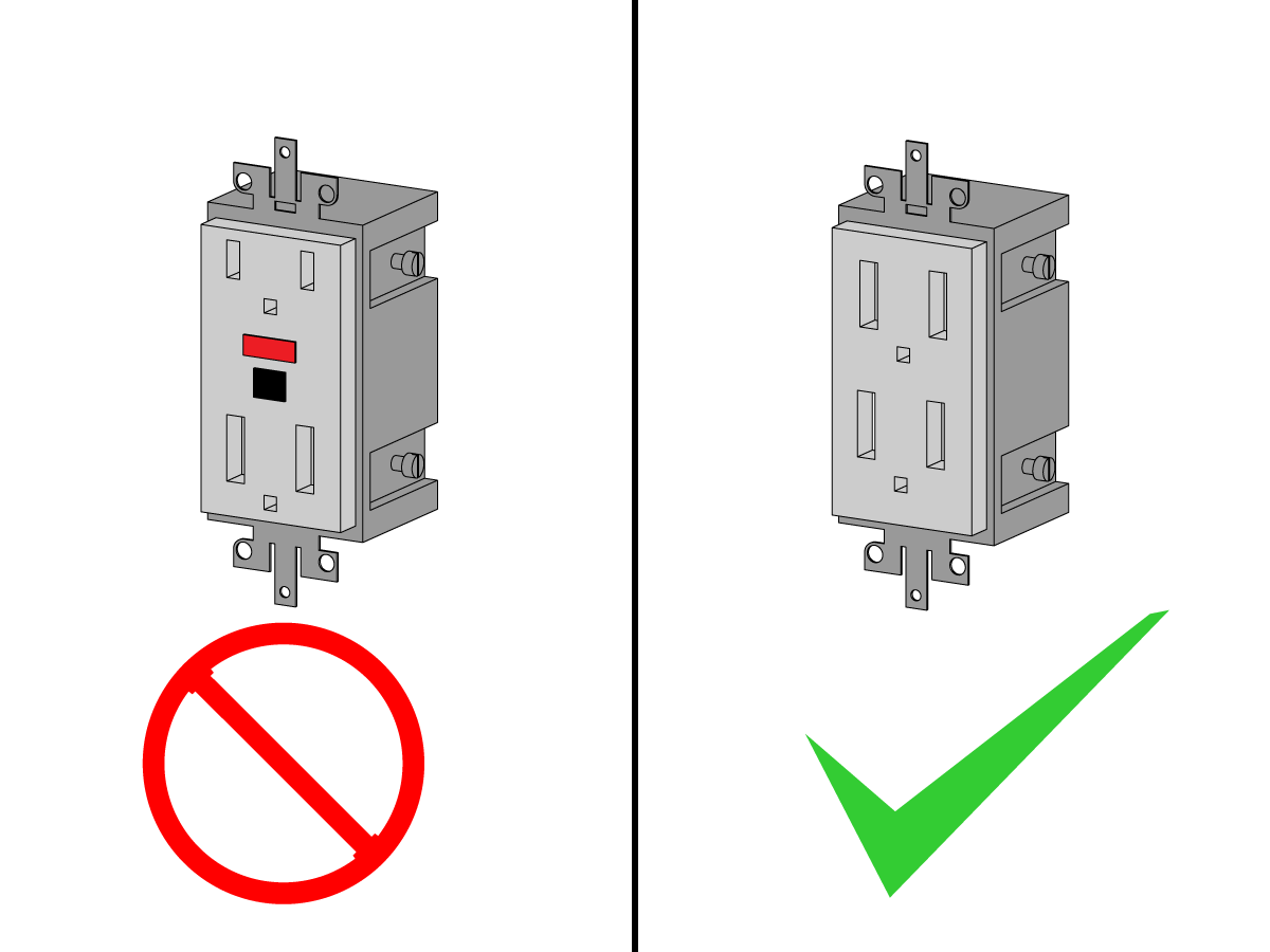
Warning: DO NOT use a GFCI circuit to run the servo control box.

The Servo Control requires a  115V or 230V AC single phase supply. To turn on your Servo Control:

  1.  Plug the control box into a power source. Check the required voltage on the back of the control box [1] and verify that you power source is correct. This image shows a 230V control box. 
  2. Press 0 on the rear panel Power switch to make sure that the Servo Control power is off.
  3. Connect the control cables (MOTOR/BRAKE and ENCODER) from the table/indexer.
  4. Connect the remote input (CNC Interface) cable from the mill (and/or the RS-232 UP cable from the PC or CNC Mill).
  5. Connect the Servo Control power cord to a 120VAC, single-phase, 50/60 Hz power supply. Press 1 on the rear panel Power switch to power on the Servo Control.
  6. The Servo Control runs a self-test and then displays: To begin Clear Alarms then Press Cycle Start. If the display gives an alarm message, refer to 8.4 Rotary Servo Control Box - Troubleshooting for more information. The numbers remain in the display for only about one second. The Por On message indicates that the motors are turned off. This is normal.
  7. Pull the Emergency Stop to disengage it, if it is set. Press a key to continue operation.

Initialize Servo Control to Factory Default Parameters

This procedure tells you how to initialize a rotary servo control box to match the correct rotary model. Power on the control. 

Four Line Display Control Boxes:

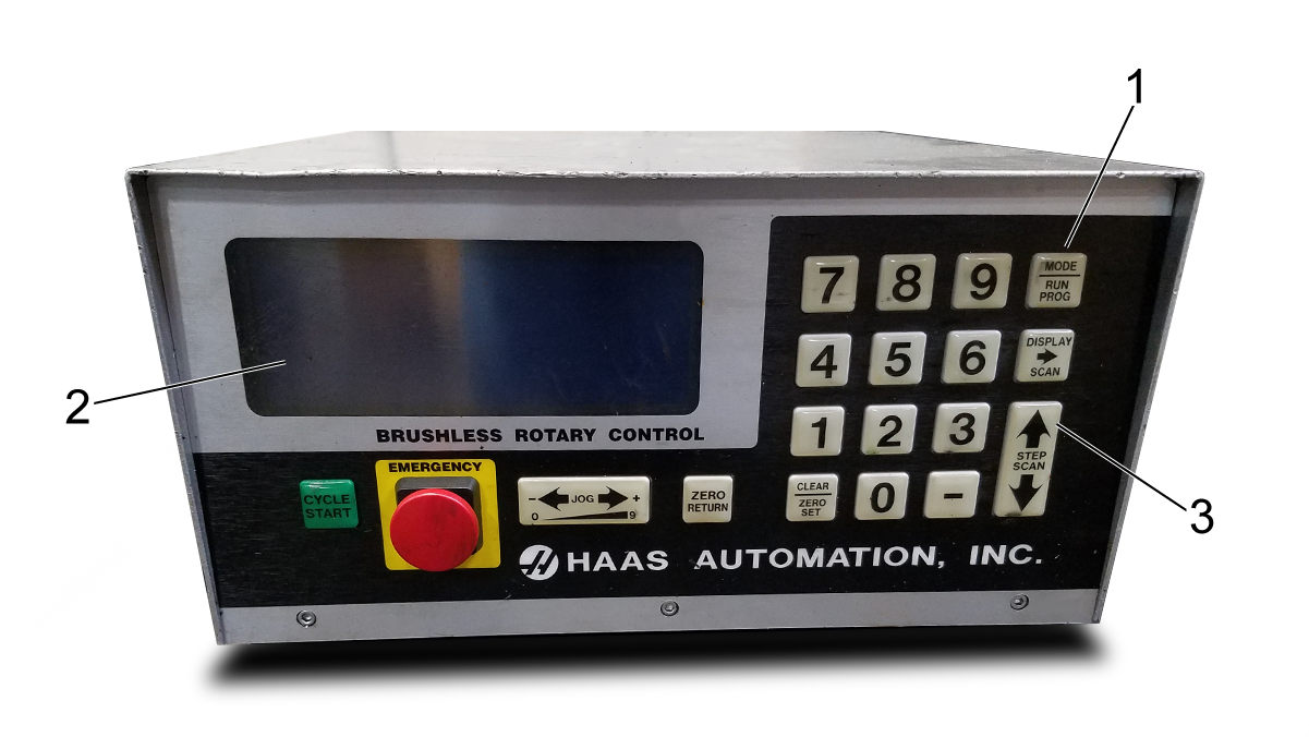
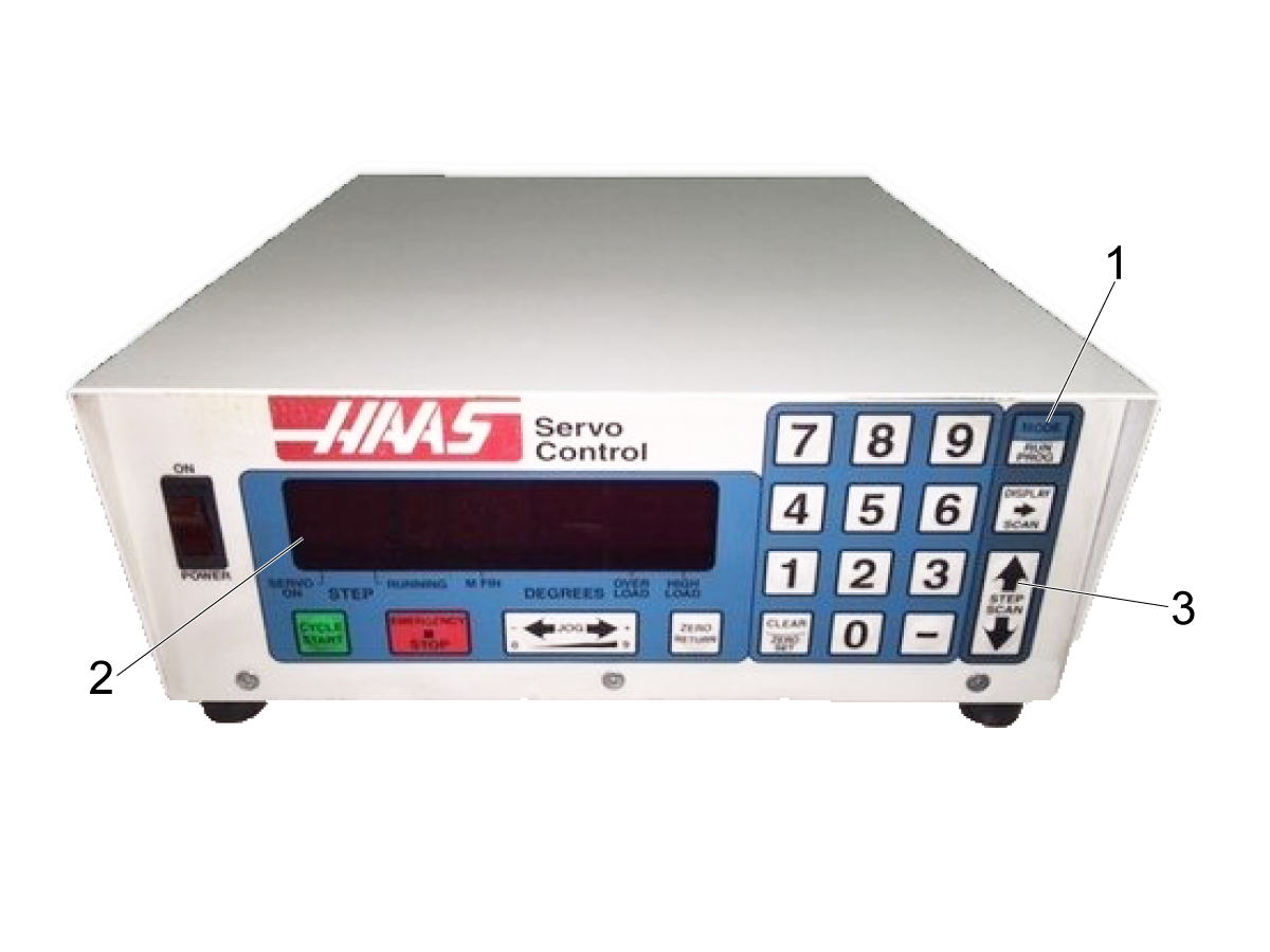
Power on the control. Press MODE/RUN-PROG [1] to put the control into Program Mode. The display starts flashing. Press and hold Step-Scan Up Arrow [3] for (5) seconds. 

Note: The size of the rotary platter is the parent name of the rotary. 

 Note: If you get an error code, contact Haas Service to unlock your control box. Before calling Haas record the numbers from parameter 24 and 30.

Press and hold CLEAR/ZERO SET for (5) seconds. The display shows a rotary model blinking on the top left. The blinking text is the parent name or platter size of the rotary. Use DISPLAY SCAN to find the parent name for the rotary and press CYCLE START to select. Now the version of the rotary will be blinking to the right of the parent name. 

Note: Legacy option is for older brushless models. For example, rotaries with sigma one motors. 

Use Display Scan to move through the options and CYCLE START to select the model and version (P code) and wait a few seconds for the controller to initialize and load the new set of parameters. The model and version of the rotary can be found on the serial plate on the rotary. 

Press MODE/RUN‑PROG to set the default values parameters for the rotary unit. The display stops flashing.

Power off the control. Connect the box to the rotary unit. Power on the control and press CYCLE START and ZERO RETURN.

Single Line Display Control Boxes: 

 Power on the control. Press MODE/RUN-PROG [1] to put the control into Program Mode. The display starts flashing.

Press and hold Step-Scan Up Arrow [3] for (5) seconds. On a brush control, “01PP 1” appears on the display [2]. On a brushless control, “01UU 1” appears on the display.

Note: If you get an error code, contact Haas Service to unlock your control box. Before calling Haas record the numbers from parameter 24 and 30.

Press and hold CLEAR/ZERO SET for (5) seconds. The display shows a rotary model blinking. Use DISPLAY SCAN to find the model for which you wish to initialize the control.

Press CYCLE START. Wait a few seconds for the controller to initialize and load the new set of parameters. Press MODE/RUN‑PROG to set the default values parameters for the rotary unit. The display will stop flashing.

Power off the control. Connect the box to the rotary unit. Power on the control and press CYCLE START and ZERO RETURN.

Finding the Zero Position

To find the zero position automatically:

Press ZERO RETURN to start the automatic homing operation.

When the table/indexer stops, the display indicates: 01 Pnnn.nnn.

If the display shows a non-zero number, press CLEAR/ZERO SET for three seconds.

Introduction

The Servo Control can be installed to communicate with your mill in two different ways:

  • Remote input using CNC Interface Cable (two signal method), and/or
  • RS-232 Interface. (Refer to the RS-232 Interface section tab for detail information on this connection.)

Servo Control Relay

The relay inside the servo control has a maximum rating of 2 amps (1 amp for HA5C) at 30 volts DC. It is programmed as either a normally closed (closed during cycle) or a normally open after cycle relay. Refer to the “Parameters” section. It is intended to drive other logic or small relays, it will not drive other motors, magnetic starters, or loads exceeding 100 watts. If the feedback relay is used to drive another DC relay (or any inductive load), install a snubber diode across the relay’s coil in the opposite direction of coil current flow Failure to use this diode, or other arc suppression circuitry or inductive loads, damages the contacts of the relays.

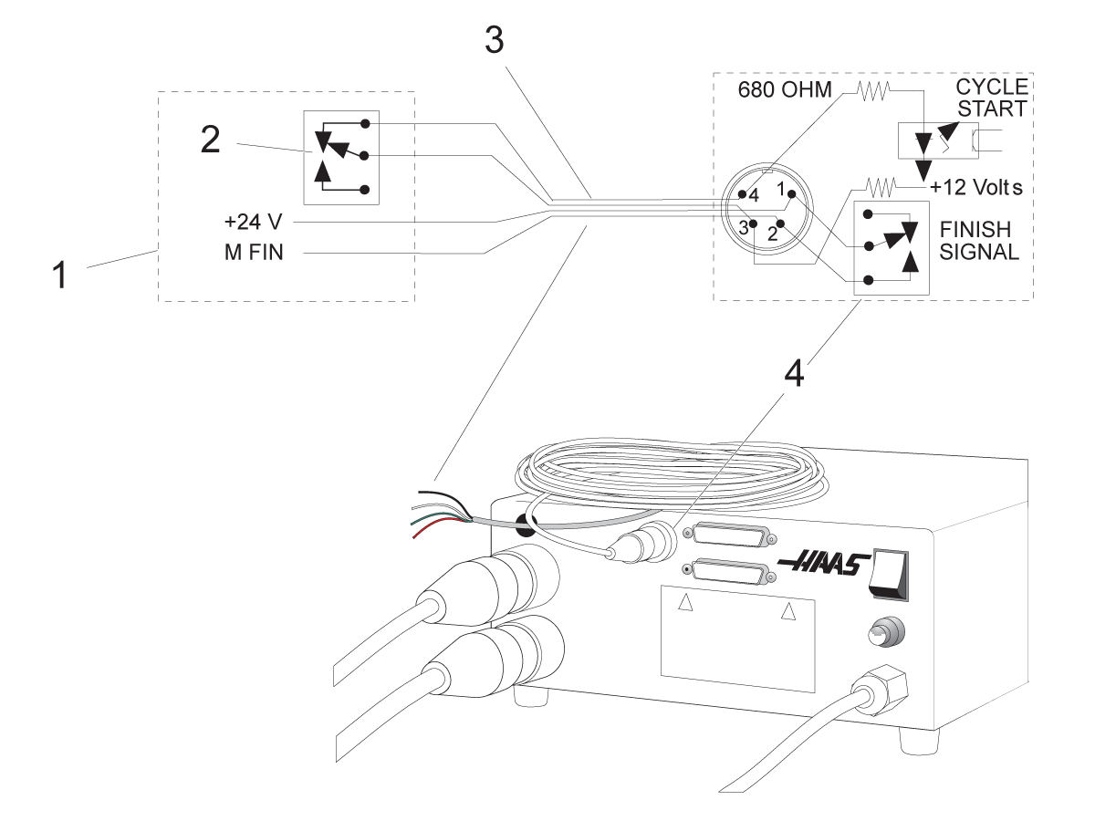
Servo Control Relay:

[1] CNC Mill Internal,

[2] M Function Relay,

[3] CNC Interface Cable,

[4] Servo Control Internal

  1. Use an ohmmeter to measure resistance across pins 1 and 2, to test the relay.

    The reading should be infinite (open contacts), with the servo control off.
  2. If a low resistance is measured (not infinite), the relay has failed and it must be replaced.

Remote Operation with CNC Equipment

NOTE: All Haas Servo Controls come standard with 1 CNC interface cable. Additional CNC interface cables can be ordered (Haas P/N CNC).

CNC mills have miscellaneous functions called M-Codes. These control external switches (relays) that turn on or off other mill functions (e.g., spindle, coolant, etc.). The Haas remote cable CYCLE START pins are hooked into the normally open contacts of a spare M-Code Function relay. Our remote cable feedback pins are then connected to the M-Code-finished pins (M-FIN), an input to the mill control that tells the mill to continue to the next block of information. The interface cable is Haas P/N: CNC.

Connecting the Servo Control box to Mill

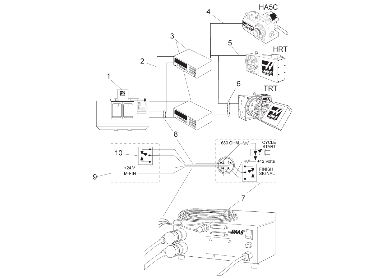
The Haas servo control has two signals, input and output. The mill tells the rotary control to index (an input), it indexes, and then sends a signal back to the mill that the index (an output) has been completed. This interface requires four wires; two for each signal, and from the rotary control remote input and from the mill.

CNC Interface Cable:

[1] CNC Mill

[2] RS-232 Cables

[3] Haas Servo Control (2 for TRT)

[4] Indexer Control Cables

[5] HRT Control Cables

[6] TRT Control Cables (2 sets)

[7] Servo Control Internal

[8] CNC Interface Cables

[9] CNC Mill Internal

[10] M Function Relay

The CNC Interface Cable provides these two signals between the mill and the Haas Servo Control. Since most CNC machines are equipped with spare M-codes, semi-fourth axis machining is achieved by connecting one end of the CNC Interface Cable to any of these spare relays (switches) and the other to the Haas Servo Control.

The Servo Control stores rotary position programs in memory and each pulse of the mill relay triggers the Servo Control to move to its next programmed position. Once the move is complete, the Servo Control signals that it has finished and is ready for the next pulse.

A remote input socket (CYCLE START and FINISH SIGNAL) is provided on the servo control back panel. Remote input consists of a CYCLE START and a FINISH SIGNAL command. To connect to the remote, a connector (contact your dealer) is used to trigger the servo control from any one of several sources. The cable connector is a male four-pin DIN connector. The Haas Automation part number is 74-1510 (Amphenol part number is 703-91-T-3300-1). The Haas Automation part number for the panel receptacle on the rear panel of the Servo Control is 74-1509 (Amphenol part number 703-91-T-3303-9).

For CYCLE START and FINISH SIGNAL operation:

1  When pins 3 and 4 are connected to each other for a minimum of 0.1 seconds, the servo control moves one cycle or step in the program.

When CYCLE START is used, pin 3 supplies a positive 12 volts at 20 milliamps and pin 4 is connected to the diode of an opto-isolator that grounds to chassis. Connecting pin 3 to pin 4 causes a current to flow through the diode of the opto-isolator, triggering the control.

NOTE: If the control is used around high-frequency equipment, such as electric welders or induction heaters, shielded wire must be used to prevent false triggering by radiated EMI (electromagnetic interference). The shield should be attached to earth ground.

2.  To move again, pins 3 and 4 must open for a minimum of 0.1 seconds and then repeat step 1.

CAUTION: Under no circumstances apply power to pins 3 and 4; a relay closure is the safest way to interface the control.

3. If your application is in an automatic machine (CNC mill), the feedback lines (FINISH SIGNAL pins 1 and 2) are used. Pins 1 and 2 are connected to the contacts of a relay inside the control and have no polarity or power on them. They are used to synchronize the automatic equipment with the servo controller.

4.  The feedback cables tell the mill that the rotary unit has finished. The relay can be used to FEED HOLD NC machine movements, or can be used to cancel an M function. If the machine is not equipped with this option, an alternative may be to dwell (pause) longer than it takes to move the rotary unit. The relay triggers for all CYCLE START closures, except G97.

Remote Operation with Manual Equipment

The remote connection is used to index the Servo Control other than by the START switch. For example, using the optional Haas remote quill switch, every time the quill handle is retracted it touches a clamped micro switch, automatically indexing the unit. You can also use the switch to index the unit automatically during milling. For example, every time the table comes back to a specific position, a bolt on the table can press the switch, indexing the unit.

In order to index the Servo Control, pins 3 and 4 need to be connected (do not apply power to these wires). Connection at pin 1 and 2 are not needed for the Servo Control to operate. However, pins 1 and 2 could be used to signal another option, such as an automatic drilling head.

A color-coded cable is available to help with the installation (M-Function control); the cable colors and pin designation are:

Pin Color
1 Red
2 Green
3 Black
4 White

HA5C Remote Input Example:

A common application for the HA5C is dedicated drilling operations. The CYCLE START wires are connected to a switch that closes when the drill head retracts, and the FINISH SIGNAL wires are connected to the Start wires of the drill head. When the operator pushes CYCLE START, the HA5C indexes to position and triggers the drill head to drill the hole.

The switch mounted to the top of the drill head indexes the HA5C when the drill retracts. This results in an endless loop of indexing and drilling. To stop the cycle, enter a G97 as the last step of the control. The G97 is a No Op code that tells the control not to send the feedback so the cycle can be stopped.

Remote Operation with FANUC CNC Control

There are several requirements that must be met before a Haas Servo Control (HTRT and HA5C) can be interfaced with a FANUC controlled mill. These are as follows:

  1. FANUC control with custom macro enabled and Parameter 6001, bits 1 and 4 set to 1.
  2. A serial port on the FANUC control must be available for use by the Haas Servo Control while DPRNT program is running.
  3. 25’ RS-232 shielded cable (DB25M/DB25M).
DB25M DB25M
1 1
2 2
3 3
4 4
5 5
6 6
7 7
8 8
20 20

4 Shielded M-code relay cable

Once the requirements have been met, revise the parameters of the Haas Servo Control. These are the parameters that need to be changed.

Servo Control Parameters

Initial settings. Change these only after the interface is functioning.

Parameter Value
1 1
2 0
5 0
8 0
10 0
12 3
13 65535
14 65535
21 Refer to the Parameter 21 Table
26 Refer to Parameter 26 Table
31 0
33 1

Values For Parameter 21

Value Definition
0 RS-232 Upload/Download Programs
1 U-Axis
2 V-Axis
3 W-Axis
4 X-Axis
5 Y-Axis
6 Z-Axis
7,8,9 Reserved

Values For Parameter 26

Value Definition
0 110
1 300
2 600
3 1200
4 2400
5 4800
6 7200
7 9600
8 19200

Fanuc Parameters

The following Fanuc control parameters must be set to successfully communicate with the Haas Servo Control.

Parameter Value
Baud Rate 1200 (Initial setting.  Change this only after interface is functioning)
Parity Even (Required Setting)
Stop bits 2
Flow Control XON/XOFF
Character Coding (EIA/ISO) ISO (Required setting, EIA will not work)
DPRNT EOB LF CR CR (CR is required, LF is always ignored by the Servo Control)
DPRNT Leading zeros as blank - OFF

Be certain to set FANUC parameters related to the actual serial port connected to Haas Servo Control. The parameters have been set for remote operation. A program can now be entered, or an existing program run. There are several key items to consider to ensure your program runs successfully.

DPRNT must precede every command sent to the Servo Control. The commands are sent in ASCII code and terminated by a carriage return (CR). All commands must be preceded by an axis select code (U, V, W, X, Y, Z). For example, setting parameter 21 = 6, means Z represents the axis code.

RS-232 Command Blocks

DPRNT Command Description
DPRNT [] Clear/ Reset receive buffer
DPRNT[ZGnn] Loads G-code nn into step no. 00, 0 is a place holder
DPRNT[ZSnn.nnn] Loads Step Size nnn.nnn into Step no. 00
DPRNT[ZFnn.nnn] Loads Feed Rate nnn.nnn into Step no. 00
DPRNT[ZLnnn] Loads Loop Count into Step no. 00
DPRNT[ZH] Return home immediately without M-FIN
DPRNT[ZB] Activates Remote CYCLE START without M-FIN
DPRNT[B] Activates Remote CYCLE START without M-FIN regardless of Servo Control Parameter 21 setting (Not for general use in this application)

NOTES:

  1. Use of Z"above assumes Servo Control Parameter 21 = 6.
  2. Leading and trailing 0 must be included (correct: S045.000, wrong: S45).
  3. When writing your program in the FANUC format, it is important to not to have blank spaces or carriage returns (CR) in your DPRNT statement.

DPRNT Program Example:

The following is an example of one way to program using the FANUC style.


O0001
G00 G17 G40 G49 G80 G90 G98
T101 M06
G54 X0 Y0 S1000 M03
POPEN (Open FANUC serial port)
DPRNT [ ] (Clear/Reset Haas)
G04 P64
DPRNT [ZG090] (Servo Control Step should now read "00")
G04 P64 
DPRNT [ZS000.000] (Loads Step Size 000.000 into Step 00)
G04 P64DPRNT [ZF050.000] (Loads Feed Rate 50 units/sec into Step 00)
G04 P64
Mnn (Remote Cycle Start, moves to P000.0000, sends M-FIN)
G04 P250 (Dwells to avoid DPRNT while M-FIN is still high)
G43 Z1. H01 M08
G81 Z-.5 F3. R.1 (Drills at: X0 Y0 P000.000)
DPRNT [ ] (Make certain Haas Input Buffer is Clear) 
G04 P64
#100 = 90. (Example of correct Macro substitution)
DPRNT [ZS#100[33] ] (Loads Step Size 090.000 into Step 00) (Leading Zero converted to Space Param. must be off)
G04 P64
Mnn (Remote Cycle Start moves to P090.000, sends M-FIN)
G04 P250
X0 (Drills at: X0 Y0 P090.000)
G80 (Cancels drill cycle)
PCLOS (Close FANUC serial port) 
G00 Z0 H0
M05
M30

The RS-232 Interface

There are two connectors used for the RS-232 interface; one each of male and female DB-25 connectors. To connect multiple Servo Controls, connect the cable from the computer to the female connector. Another cable can connect the first Servo Control to the second by connecting the male connector of the first box to the female connector of the second. You can connect up to nine controls in this way. The RS-232 connector on the Servo Control is used to load programs.

The RS-232 connector on the back of most personal computers is a male DB-9, so only one type of cable is required for connection to the control, or between controls. This cable must be a DB-25 male on one end and a DB-9 female on the other. Pins 1, 2, 3, 4, 5, 6, 7, 8, and 9 must be wired one-to-one. It cannot be a Null Modem cable, which inverts pins 2 and 3. To check cable type, use a cable tester to check that communication lines are correct.

The control is DCE (Data Communication Equipment), which means that it transmits on the RXD line (pin 3) and receives on the TXD line (pin 2). The RS-232 connector on most PCs is wired for DTE (Data Terminal Equipment), so no special jumpers should be required.

PC RS-232 COM1 Setup

PC Parameter Value
Stop Bits 2
Parity EVEN
Baud Rate 9600
Data Bits 7

RS-232 Daisy Chain Two Servo Controllers for TRT:

[1] PC with RS-232 DB-9 Connector

[2] RS-232 Cable DB-9 to DB-25 straight through

[3] Servo Control A-Axis

[4] RS-232 Cable DB-25 to DB-25 straight through

[5] Servo Control B-Axis

The RS-232 DOWN (out line) DB-25 connector is used when multiple controls are used. The first control’s RS-232 DOWN (out line) connector goes to the second controller’s RS-232 UP (in line) connector, etc.

If Parameter 33 is 0, the CTS line can still be used to synchronize output. When more than one Haas rotary control is daisy-chained, data sent from the PC goes to all of the controls at the same time. That is why an axis selection code (Parameter 21) is required. Data sent back to the PC from the controls is programmed together using digital logic OR gates (OR-ed) so that, if more than one box is transmitting, the data will be garbled. Therefore, the axis selection code must be unique for each controller. The serial interface may be used in either a remote command mode or as an upload/download path.

Recently Viewed Items

You Have No Recently Viewed Items Yet

Feedback
Haas Logo

Haas Delivered Price

This price includes shipping cost, export and import duties, insurance, and any other expenses incurred during shipping to a location in France agreed with you as a buyer. No other mandatory costs can be added to the delivery of a Haas CNC Product.

KEEP UP WITH THE LATEST HAAS TIPS AND TECHNOLOGY...

Sign up now!   

HAAS TOOLING ACCEPTS THE FOLLOWING:

  • Service & Support
  • Owners
  • Request Service
  • Operator Manuals
  • Haas Parts
  • Rotary Repair Request
  • Pre-Install Guides
  • Shopping Tools
  • Build & Price a New Haas
  • Available Inventory
  • The Haas Price List
  • CNCA Financing
  • About Haas
  • Accessibility Statement
  • DNSH Statement
  • Export Compliance
  • Careers
  • Certifications & Safety
  • Contact Us
  • History
  • Terms & Conditions
  • Haas Tooling Terms & Conditions
  • Privacy
  • Warranty
  • Haas Community
  • Haas Certification Program
  • Haas Motorsports
  • Gene Haas Foundation
  • Haas Technical Education Community
  • Events
  • Join the Conversation
  • Facebook
  • X
  • Flickr
  • YouTube
  • LinkedIn
  • Instagram
  • TikTok
© 2026 Haas Automation, Inc – CNC Machine Tools

This site is protected by reCAPTCHA and the Google Privacy Policy and Terms of Service apply.

2800 Sturgis Rd., Oxnard, CA 93030
Toll Free: (888) 817-4446 / Fax: 805-278-8554