My Haas Welcome,
!
Haas Tooling MyHaas/HaasConnect Sign In Register Haas Tooling MyHaas/HaasConnect Sign Out Welcome, My Machines Latest Activity My Quotes My Account My Users Sign Out
Find Your Distributor
  1. Select Language
    1. English
    2. Deutsch
    3. Español - ES
    4. Español - MX
    5. Français
    6. Italiano
    7. Português
    8. Český
    9. Dansk
    10. Nederlands
    11. Magyar
    12. Polski
    13. Svenska
    14. Türkçe
    15. 中文
    16. Suomi
    17. Norsk
    18. الإنجليزية
    19. български
    20. Hrvatski
    21. Ελληνικά
    22. Română
    23. Slovenský
    24. Slovenščina
    25. 한국어
    26. 日本語
    27. Українська
  • machines Main Menu
    • Vertical Mills
      Vertical Mills
      Vertical Mills View All
      • Vertical Mills
      • VF Series
      • Universal Machines
      • VR Series
      • VP-5 Prismatic
      • Pallet-Changing VMCs
      • Mini Mills
      • Mold Machines
      • High-Speed Drill Centers
      • Drill/Tap/ Mill Series
      • Toolroom Mills
      • Pocket Mill
      • Compact Mills
      • Gantry Series
      • SR Sheet Routers
      • Extra-Large VMC
      • Double-Column Mills
      • 3+2 Positioning Machines
    • Multi-Axis Solutions
      Multi-Axis Solutions
      Multi-Axis Solutions View All
      • Multi-Axis Solutions
      • Y-Axis Lathes
      • 5-Axis Mills
    • Lathes
      Lathes
      Lathes View All
      • Lathes
      • ST Series
      • Dual-Spindle
      • Box Way Series
      • Toolroom Lathes
      • Chucker Lathe
      • Pocket Lathe
      • Haas Bar Feeders
    • Horizontal Mills
      Horizontal Mills
      Horizontal Mills View All
      • Horizontal Mills
      • 50-Taper
      • 40-Taper
    • Rotaries & Indexers
      Rotaries & Indexers
      Rotaries & Indexers View All
      • Rotaries & Indexers
      • Rotary Tables
      • Indexers
      • 5-Axis Rotaries
      • Extra-Large Rotaries
    • Special Series
      Special Series
      Special Series View All
      • Special Series
      • EU_Series_Redirect
    • Automation Systems
      Automation Systems
      Automation Systems View All
      • Automation Systems
      • Mill Automation
      • Lathe Automation
      • Automatic Parts Loaders
      • Automation Models
    • Desktop Machines
      Desktop Machines
      Desktop Machines View All
      • Desktop Machines
      • Desktop Mill
      • Desktop Lathe
      • Control Simulator, Standard
      • Control Simulator, Premium
    • Shop Equipment
      Shop Equipment
      Shop Equipment View All
      • Shop Equipment
      • Knee Mill
      • Haas Manual Lathes
      • Haas Saws
    • Fabrication Machines
      Fabrication Machines
      Fabrication Machines View All
      • Fabrication Machines
      • Laser Cutting Machines
      • CNC Press Brakes
    • QUICK LINKS Special Series  Special Series 
      EU SERIES EU SERIES BUILD & PRICE | PRICE LIST BUILD & PRICE | PRICE LIST In-Stock Machines In-Stock Machines WHAT’S NEW WHAT’S NEW YOUR FIRST CNC YOUR FIRST CNC
      SHOPPING TOOLS
      • Build & Price a Haas
      • Price List
      • Available Inventory
      • CNCA Financing
      WANT TO TALK TO SOMEONE?

      A Haas Factory Outlet (HFO) can answer your questions, and walk you through your best options.

      CONTACT YOUR DISTRIBUTOR >
  • Options Main Menu
    • The Haas Control Value Option Packages
      Value Option Packages
      Value Option Packages View All
      • Value Option Packages
    • Product Image Spindles
      Spindles
      Spindles View All
      • Spindles
    • Product Image Tool Changers
      Tool Changers
      Tool Changers View All
      • Tool Changers
    • Product Image 4th- | 5th-Axis
      4th- | 5th-Axis
      4th- | 5th-Axis View All
      • 4th- | 5th-Axis
    • Product Image Turrets & Live Tooling
      Turrets & Live Tooling
      Turrets & Live Tooling View All
      • Turrets & Live Tooling
    • Product Image Probing
      Probing
      Probing View All
      • Probing
    • Haas Chip & Coolant Management Chip & Coolant Management
      Chip & Coolant Management
      Chip & Coolant Management View All
      • Chip & Coolant Management
    • The Haas Control The Haas Control
      The Haas Control
      The Haas Control View All
      • The Haas Control
    • Product Image Product Options
      Product Options
      Product Options View All
      • Product Options
    • Product Image Tooling & Fixturing
      Tooling & Fixturing
      Tooling & Fixturing View All
      • Tooling & Fixturing
    • Product Image Workholding
      Workholding
      Workholding View All
      • Workholding
    • Product Image 5-Axis Solutions
      5-Axis Solutions
      5-Axis Solutions View All
      • 5-Axis Solutions
      • 5 Easy Steps to 5-Axis
    • QUICK LINKS Special Series  Special Series 
      EU SERIES EU SERIES BUILD & PRICE | PRICE LIST BUILD & PRICE | PRICE LIST In-Stock Machines In-Stock Machines WHAT’S NEW WHAT’S NEW YOUR FIRST CNC YOUR FIRST CNC
      SHOPPING TOOLS
      • Build & Price a Haas
      • Price List
      • Available Inventory
      • CNCA Financing
      WANT TO TALK TO SOMEONE?

      A Haas Factory Outlet (HFO) can answer your questions, and walk you through your best options.

      CONTACT YOUR DISTRIBUTOR >
  • Why Haas Main Menu
      Discover the Haas Difference
    • Why Haas
    • MyHaas
    • Education Community
    • Industry 4.0
    • Haas Certification
    • Customer Testimonials
  • Service Main Menu
      Welcome to Haas Service
      SERVICE HOME Operator’s Manuals How-To Procedures Troubleshooting Guides Preventive Maintenance Haas Parts Haas Tooling Videos
  • Videos Main Menu
  • Main Menu
    • View All
    • View All
    • View All
    • View All
      • HTEC Curriculum Support
      • Haas Value Option Packages (VOP) Journey
    • View All
      • Haas 10 kg Cobot Package
      • Cobot Kits
      • DC-1 Drill Center
      • CNC Sales News
      • Do More With Your Haas
    • View All
    • View All
      • contact-us-test
      • 4 - AUTOMATION SYSTEMS
      • Carousel-V2
      • expert test
      • Demo_Day_Trident-test
      • Link Test
      • image-sale-tag-test
      • article-list-test
      • Haas 25 kg Robot Package
      • test-algolia-page
    • View All
    • View All
    • View All
    • View All
      • calc-test
    • View All
    • QUICK LINKS Special Series  Special Series 
      EU SERIES EU SERIES BUILD & PRICE | PRICE LIST BUILD & PRICE | PRICE LIST In-Stock Machines In-Stock Machines WHAT’S NEW WHAT’S NEW YOUR FIRST CNC YOUR FIRST CNC
      SHOPPING TOOLS
      • Build & Price a Haas
      • Price List
      • Available Inventory
      • CNCA Financing
      WANT TO TALK TO SOMEONE?

      A Haas Factory Outlet (HFO) can answer your questions, and walk you through your best options.

      CONTACT YOUR DISTRIBUTOR >
  • Haas Tooling Main Menu
  • Haas Service Parts Main Menu

My Haas Welcome,
!
Haas Tooling MyHaas/HaasConnect Sign In Register Haas Tooling MyHaas/HaasConnect Sign Out Welcome, My Machines Latest Activity My Quotes My Account My Users Sign Out
Find Your Distributor
  1. Select Language
    1. English
    2. Deutsch
    3. Español - ES
    4. Español - MX
    5. Français
    6. Italiano
    7. Português
    8. Český
    9. Dansk
    10. Nederlands
    11. Magyar
    12. Polski
    13. Svenska
    14. Türkçe
    15. 中文
    16. Suomi
    17. Norsk
    18. الإنجليزية
    19. български
    20. Hrvatski
    21. Ελληνικά
    22. Română
    23. Slovenský
    24. Slovenščina
    25. 한국어
    26. 日本語
    27. Українська
×

Search Results

Web Pages

Images

    • <
    • 1
    • >

6 - Rotary - Maintenance

Rotary - Service Manual


  • 1 - Rotary - Introduction
  • 2 - Rotary - CNC Installation
  • 3 - Rotary - CNC Removal
  • 4 -Rotary - SCOL - Installation
  • 5 - Rotary - Operation
  • 6 - Rotary - Maintenance
  • 7 - Rotary - Workholding
  • 8 - Rotary - Troubleshooting

Go To :

  • 6.1 Rotary - Maintenance
  • 6.2 Rotary - Lubrication Chart
  • 6.3 Rotary - Service Replacements
  • 6.4 Rotary - Service Procedures
  • 6.5 Servo Control - Battery Replacement
  • 6.6 Rotary - Backlash Testing
  • 6.7 Rotary Belt Tension

6.1 Rotary - Maintenance

Recently Updated

Rotary - Maintenance


RD0094

Revision B - 05/2026

Introduction

Haas rotary units require very little routine servicing. However, it is very important to perform these services to ensure reliability and long operating life. 

Maintenance Item Interval

Drain and refill rotary/indexer unit

Every two years

Indexer Lubrication

1

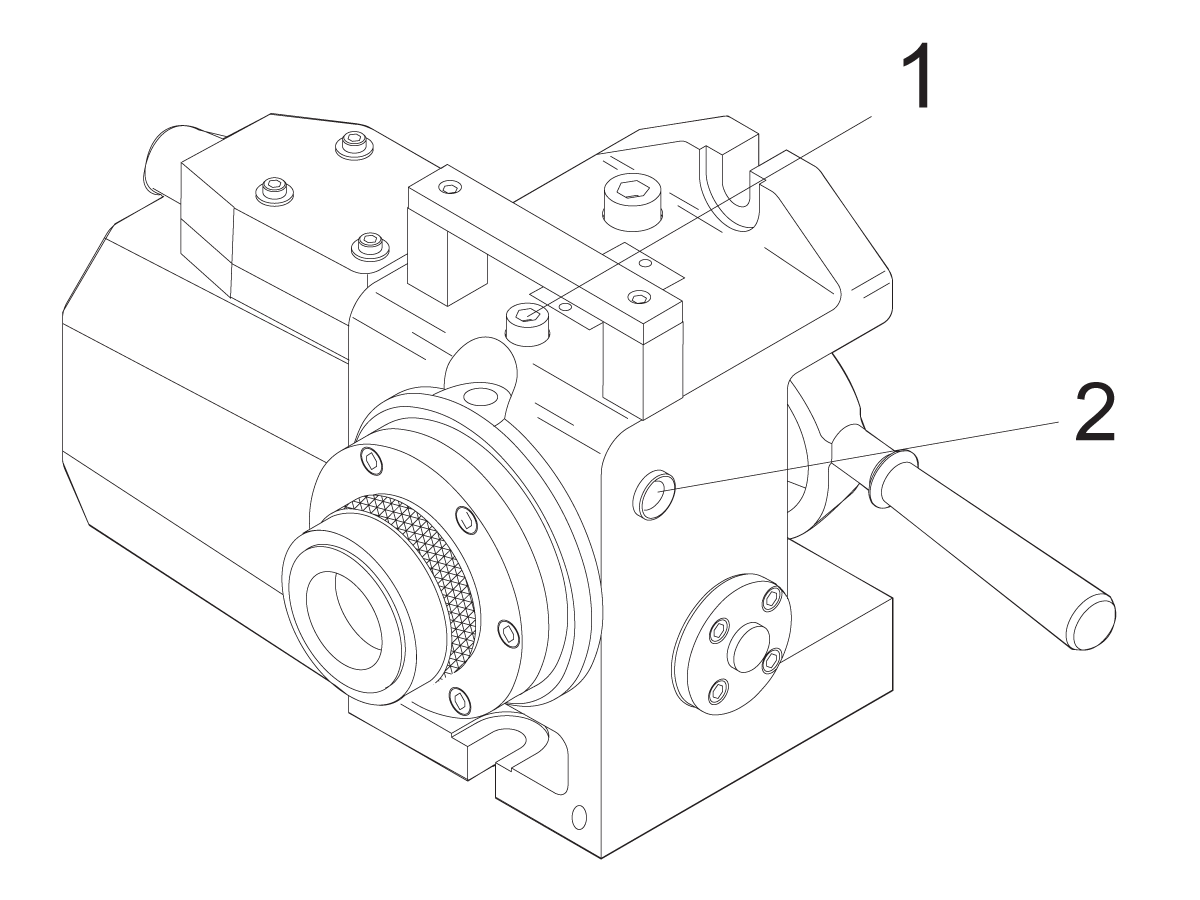
Fill Port Location for Rotary Indexer: [1] Lube Fill Port, [2] Sight Glass 

To check and add oil to the HA5C:

1. The unit must be stopped to accurately read the oil level.

2. The sight-glass is located on the side of the unit [2]. Use the sight glass to check the oil level. The lube level should reach the mid-point of the sight glass.

3. To add lube to the Rotary Indexer, locate and remove the Pipe-plug from the lube fill port. This is located under the handle on top of the casting [1].

4. If necessary, add oil until the level reaches the mid-point of the eye.

5. Replace the lube fill port Pipe-plug and tighten.

HRT Lubrication

To check and add oil to the HRT160/210/310:

1. The unit must be stopped and upright to accurately read the oil level.
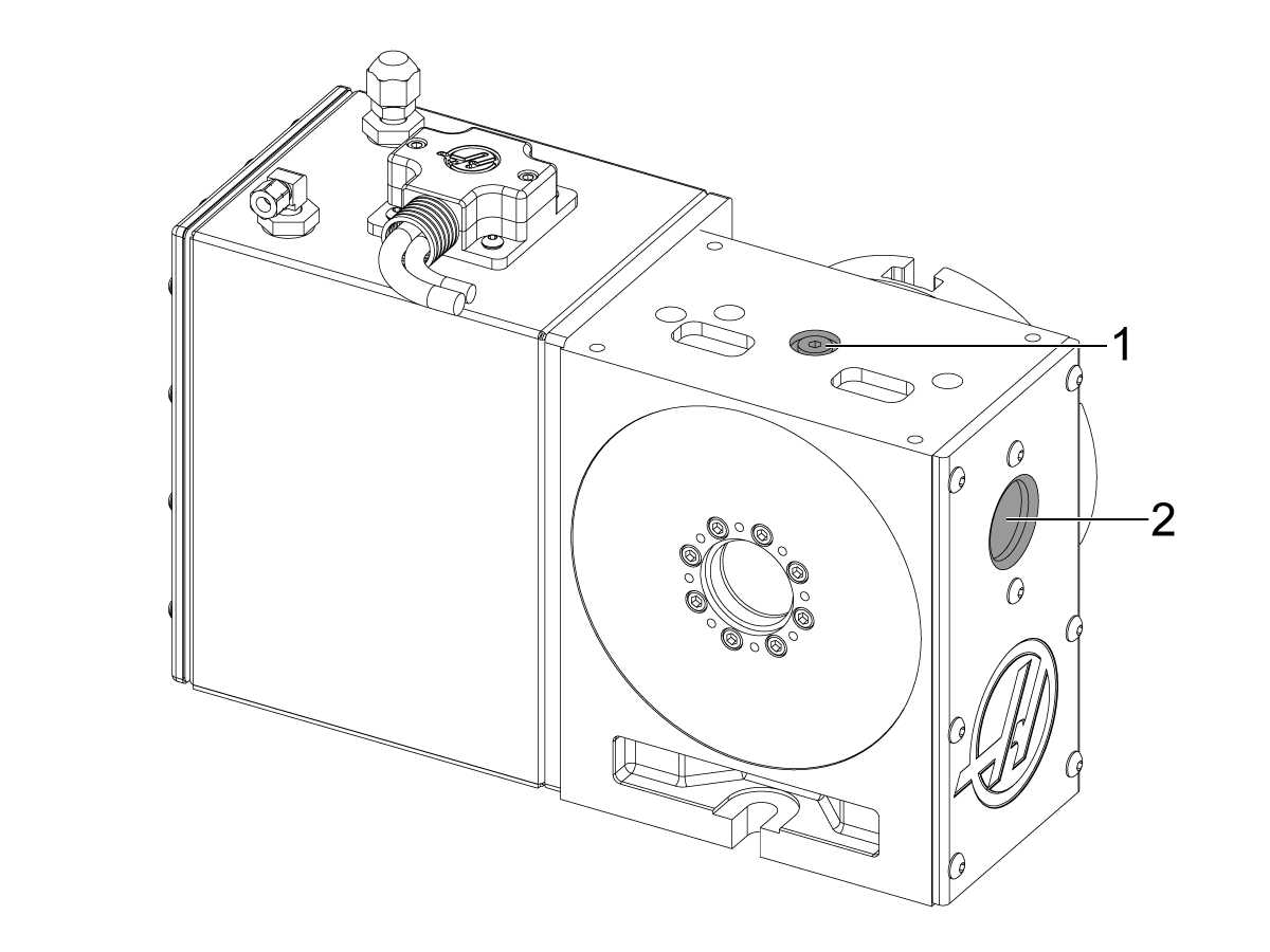
2. Use the sight glass [2] to check the oil level. The lube level should reach the top of the sight glass. HRT210SHS - The oil level should show no more than 1/3 on the sight glass.
3. To add oil to the Rotary Indexer, remove the pipe plug from the oil fill port [1] located under the top plate.
4. Add oil (HRT110, HRT210SHS and TR110) until proper level is reached.
5. Replace the fill port bolt and tighten.

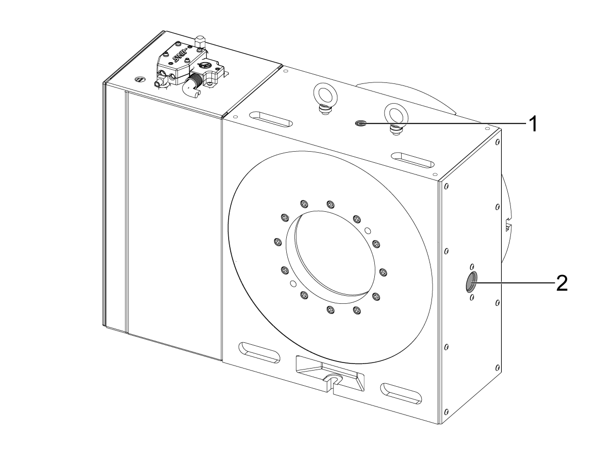
Fill Port Location for HRT450  built after September 2019

Note:  These HRT450 units have a air brake system they can be identified by the black brake disk: 

[1] Gear Oil Fill Port, [2] Sight Glass

To check and add oil to the HRT450:

1. The unit must be stopped and upright to accurately read the oil level.

2. Use the sight glass [2] to check the oil level. The lube level should reach the top of the sight glass.

3. To add oil, remove the pipe plug from the oil fill port [1] located under the top plate.

4. Add oil until proper level is reached.

5. Replace the fill port bolt and tighten.

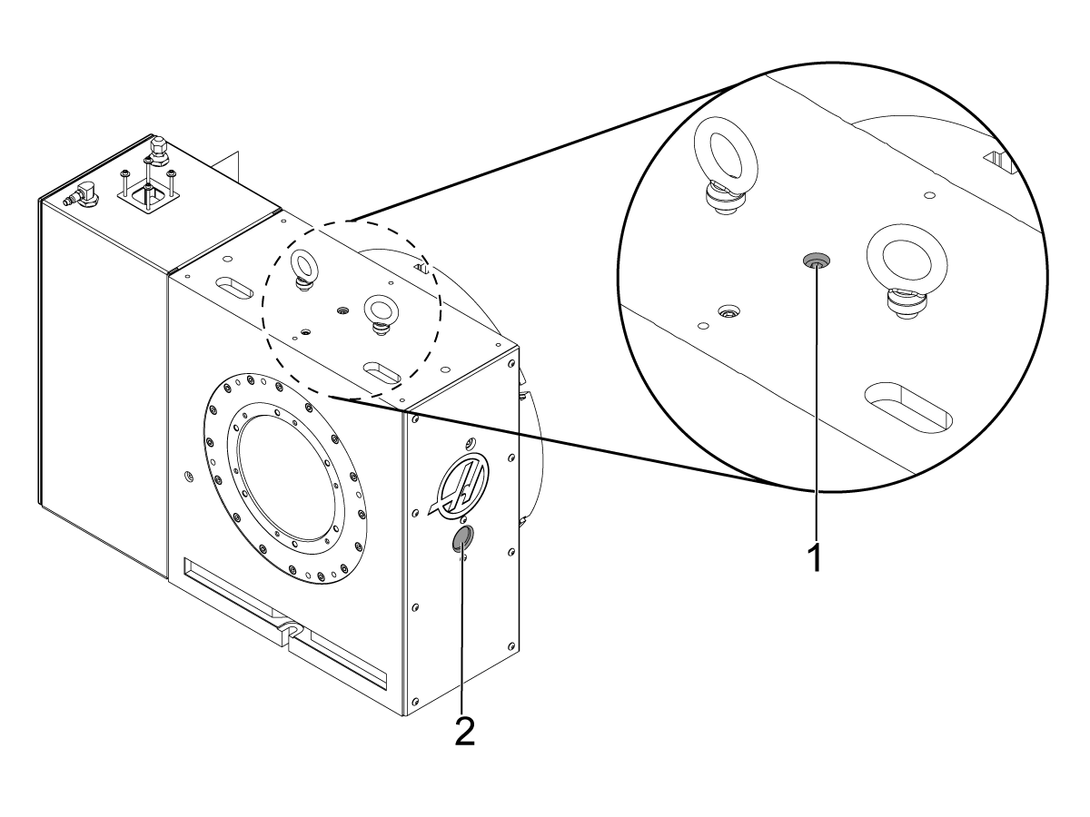
Fill Port Location for HRT450 built before September 2019

 Note:  These HRT450 units have a hydraulic brake system they can be identified by a silver brake disk: 

[1] Gear Oil Fill Port, [2] Sight Glass

To check and add oil to the HRT450:

1. The unit must be stopped and upright to accurately read the oil level.

2. Use the sight glass [2] to check the oil level. The lube level should reach the top of the sight glass. 

3. To add oil, remove the pipe plug from the oil fill port [1] located under the top plate.

4. Add oil until proper level is reached.

5. Replace the fill port bolt and tighten.

Updated

Fill Port Location for HRT200HS 

[1] Fill port

[2] Drain port

Note: When filling this HRT rotary, fill the port area all the way then use a controller to rotate the axis that is being filled. Rotate slowly until the port area is drained. Repeat the process until the port area no longer drains. 

It is recommended that you use a funnel when pouring oil into the rotary.

1. The unit must be stopped and upright to accurately read the oil level.

2. To drain the rotary, unscrew the drain port [2] at the bottom of the rotary. The rotary likely will be to be suspended in the air to do this. Rotary units are heavy so take appropriate safety measures while draining the oil. Clean off the oil remaining on the rotary and replace the screw.

3. To fill the rotary, unscrew the fill port at the top [1]. There are no sight glasses the port should be filled completely.


TR Lubrication

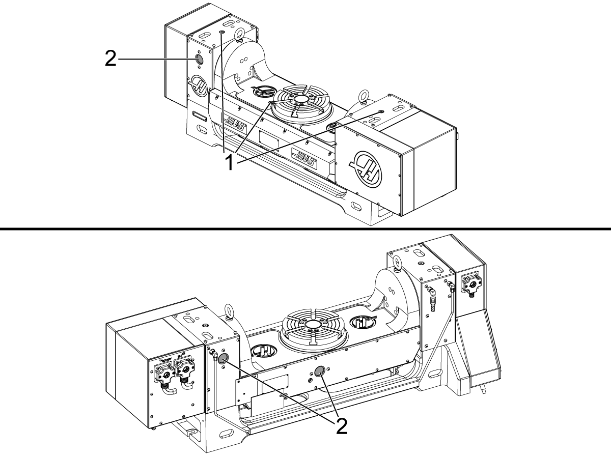
Fill Port location for Trunnion Tables: [1] Fill Ports, [2] Sight Glasses

To check and add oil to the TR or T5C:

1. The unit must be stopped and upright to accurately read the oil level.

2. Use the sight glasses [2] to check the oil level. The lube level should reach the top of both sight glasses.

3. If the level is low, fill the table through the pipe plugs [1] in the body.

4. Fill to the top of the sight glass. Do not over fill.

5. If the oil is dirty, drain and refill with clean oil.

Note: The TR310 does not have a sight glass for the tilit axis and should be filled completely.

TRT Lubrication

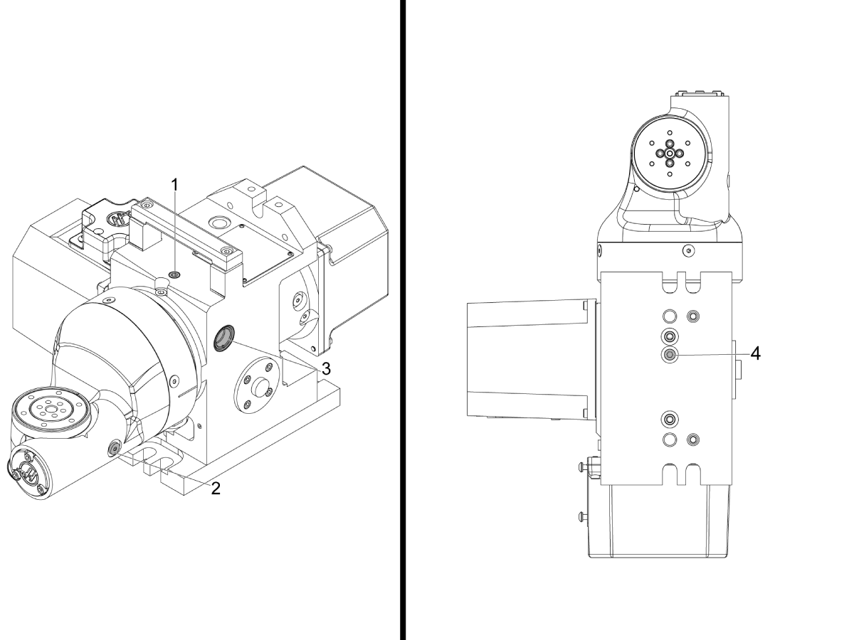
Oil change for TRT70

[1] A axis fill port.

[2] B axis fill and drain port

[3] A axis oil sight glass

[4] A axis drain port

Note: When Filling TRT rotaries fill the port area all the way then used a controller to rotate the axis that is being filled. Rotate slowly until the port area is drained. Repeat the process until the port area no longer drains. This will need to be done for both A and B axis. 

It is recommended that you use a funnel when pouring oil into the rotary.

1. The unit must be stopped and upright to accurately read the oil level.

2. To drain the A axis unscrew the drain port [4] at the bottom of the rotary. The rotary likely will need be to be suspended in the air to do this. Rotary units are heavy so take appropriate safety measures while draining the oil. Clean off the oil remaining on the rotary and replace the screw.

3. To fill the A axis Place unscrew the fill port at the top [1]. Use the sight glass to check the oil level. The lube level should reach the mid-point of the sight glass.

4. To drain the B axis tilt axis to 90° so the drain port is pointing down and unscrew the drain port [3]. Once the rotary is empty screw the port plug back in.

5.  To fill the B axis leave the tilt axis at 90° and unscrew the drain port [2]. Remove the screws holding the oil fill port cover and remove the cover. There are no sight glasses the port should be filled completely.

There is no sight glass for the B axis the port should be filled completely. Once the rotary has been filled screw the port plug back in.

Oil change for TRT100:

[1] A axis fill port.

[2] B axis fill port.

[3] B axis drain port.

[4] A axis drain port.

Note: When Filling TRT rotaries fill the port area all the way then used a controller to rotate the axis that is being filled. Rotate slowly until the port area is drained. Repeat the process until the port area no longer drains. This will need to be done for both A and B axis. 

It is recommended that you use a funnel when pouring oil into the rotary.

1. The unit must be stopped and upright to accurately read the oil level.

2. To drain the A axis unscrew the drain port [4] at the bottom of the rotary. The rotary likely will be to be suspended in the air to do this. Rotary units are heavy so take appropriate safety measures while draining the oil. Clean off the oil remaining on the rotary and replace the screw.

3. To fill the A axis, unscrew the fill port at the top [1]. There are no sight glasses the port should be filled completely.

4. To drain the B axis tilt axis to 90° and unscrew the drain port [3]. Only one side has a drain port check for it before tilting the rotary. Once the rotary is empty screw the port plug back in.

5.  To fill the B axis set the tilt axis to 0° and unscrew the fill port [2].

            TRT100: Remove the screws holding the oil fill port cover and remove the cover.

There is no sight glasses the port should be filled completely. Once the rotary has been filled 

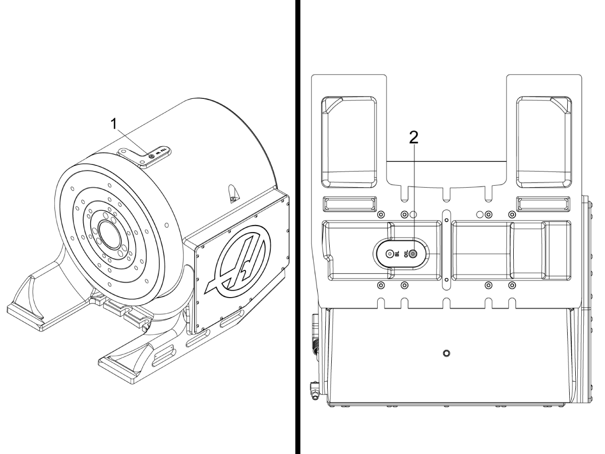
Oil change for TRT160, TRT210, and TRT310:

[1] A axis fill port.

[2] Do not use.  Warning: On TRT 160, this is a set screw that adjusts backlash. This should only be adjusted by a Haas service technician trained to adjust backlash on rotaries. 

[3] B axis drain and fill port.

[4] A axis drain port.

Note: When Filling TRT rotaries fill the port area all the way then used a controller to rotate the axis that is being filled. Rotate slowly until the port area is drained. Repeat the process until the port area no longer drains. This will need to be done for both A and B axis.

It is recommended that you use a funnel when pouring oil into the rotary.

1. The unit must be stopped and upright to accurately read the oil level.

2. To drain the A axis unscrew the drain port [4] at the bottom of the rotary. The rotary likely will be to be suspended in the air to do this. Rotary units are heavy so take appropriate safety measures while draining the oil. Clean off the oil remaining on the rotary and replace the screw. Both rotaries have two screws on the bottom.

            TRT210: The inner most screw is for the drain port. The picture to the left shows a TRT210.

            TRT310: The oil drain port is labeled.

3. To fill the A axis Place unscrew the fill port at the top [1]. There are no sight glasses the port should be filled completely.

4. To drain the B axis tilt axis to 90° and unscrew the drain port [3]. Only one side has a drain port check for it before tilting the rotary. Once the rotary is empty screw the port plug back in.

5. To fill the B axis leave the tilt axis at 90° and unscrew the drain port [2]. Remove the screws holding the oil fill port cover and remove the cover. There are no sight glasses the port should be filled completely. 

There is no sight glasses the port should be filled completely. Once the rotary has been filled 

TH Lubrication

Oil change for HT240 and HT 450:

[1] fill port.

[2] drain port.

Note: When Filling TH rotaries fill the port area all the way then used a controller to rotate the axis that is being filled. Rotate slowly until the port area is drained. Repeat the process until the port area no longer drains. 

Note: The picture shows a TH450. 

1. The unit must be stopped and upright to accurately read the oil level.

2. To drain the A axis unscrew the drain port [2] at the bottom of the rotary. The rotary likely will be to be suspended in the air to do this. Rotary units are heavy so take appropriate safety measures while draining the oil. Clean off the oil remaining on the rotary and replace the screw. 

            TH240: There is only one screw to undo from the bottom.

            TRT450: The oil drain port is the inner most port and is labled. 

3. To fill the rotary axis Place unscrew the fill port at the top [1]. There are no sight glasses the port should be filled completely.

There is no sight glasses the port should be filled completely. Once the rotary has been filled 

Coolant

Machine coolant must be water-soluble, synthetic-oil based, or synthetic based coolant/lubricant.

  • Do not use mineral cutting oils; they damage rubber components and void the warranty. 
  • Do not use pure water as a coolant; components will rust. 
  • Do not use flammable liquids as coolant. 
  • Do not submerge the unit in coolant. Keep the coolant lines on the workpiece spraying away from the rotary unit. Tool spraying and spatter are acceptable. Some mills provide flood coolant such that the rotary unit is practically submerged. Try to cut down the flow to match the job. 

Inspect the cables and gaskets for cuts or swelling. Have damaged components repaired immediately.

HRT / TRT Inspection

Adjustments

The face runout, face I.D. runout, worm play, backlash between worm and gear, and the popout are set at the factory and are not field serviceable. If any of these specifications are out of tolerance, contact your Haas Factory Outlet.

Maintenance Item Interval

Platter Face Runout 
To check the platter runout:

1. Mount an indicator to the body of the table.
2. Position the stylus on the face of the platter.
3. Index the table 360°.

The runout should be 0.0005" or less.

As needed

Platter I.D. runout.
To check the platter I.D. runout:

1. Mount the indicator to the table body.
2. Position the stylus on the platter through-hole.
3. Index the table 360°.

Runout should be:

  • HRT160 - 210 = 0.0005"
  • HRT110, HRT310 = 0.001"
  • HRT450 - 600 = 0.0015"
As needed

Backlash

Backlash is the movement error caused by space between
the worm wheel gear and worm shaft when the worm gear changes direction.
Backlash is factory set to .0003/.0004.

The table below lists the maximum allowed backlash. 

  • HRT160 = 0.0006
  • HRT210 = 0.0006
  • HRT310 = 0.0007
  • HRT450 = 0.0007
  • HRT600 = 0.0008
As needed

6.2 Rotary Lubrication Chart

Rotary

Required lubricants and refill volumes for all rotary/indexer products are listed below:

Warning: Do not put lubricant oil in hydraulic port and do not put hydraulic fluid in oil port. Doing so will damage the rotary. 

Go to www.haascnc.com/haas-service-parts to order replacement lubricants.

Instructions for doing an oil change on Rotaries can be found at 6.1 Rotary - Maintenance.

Rotary - Indexer

Rotary Model Primary Lubricant Alternate Lubricant (Domestic) Alternate Lubricant (European) Capacity Haas Part Number Safety Data Sheet
HA5C Mobil 1, 75W-90 Mobil 1, 15W-50 TBD 7 oz (0.21 L) 93-2365  Product page | SDS [PDF]
HA5C-T Mobil 1, 75W-90 Mobil 1, 15W-50 TBD 7 oz (0.21 L) 93-2365  Product page | SDS [PDF]
HA5CS Mobil 1, 75W-90 Mobil 1, 15W-50 TBD 7 oz (0.21 L) 93-2365  Product page | SDS [PDF]
HA5C(SB) Mobil 1, 75W-90 Mobil 1, 15W-50 TBD 10 oz (0.3 L) 93-2365  Product page | SDS [PDF]
T5C Mobil 1, 75W-90 Mobil 1, 15W-50 TBD

4th: 26 oz (0.76 L)

5th: 7 oz (0.21 L)

93-2365  Product page | SDS [PDF]
HA5C2 Mobil 1, 75W-90 Mobil 1, 15W-50 TBD 14 oz (0.42 L) 93-2365  Product page | SDS [PDF]
HA5C2-T Mobil 1, 75W-90 Mobil 1, 15W-50 TBD 14 oz (0.42 L) 93-2365  Product page | SDS [PDF]
T5C2 Mobil 1, 75W-90 Mobil 1, 15W-50 TBD

4th: 26 oz (0.76 L)

5th: 14 oz (0.42 L)

93-2365  Product page | SDS [PDF]
HA5C3 Mobil 1, 75W-90 Mobil 1, 15W-50 TBD 21 oz (0.62L) 93-2365  Product page | SDS [PDF]
HA5C3-T Mobil 1, 75W-90 Mobil 1, 15W-50 TBD 21 oz (0.62L) 93-2365  Product page | SDS [PDF]
T5C3 Mobil 1, 75W-90 Mobil 1, 15W-50 TBD

4th: 26 oz (0.76 L)

5th: 21 oz (0.62 L)

93-2365  Product page | SDS [PDF]
HA5C4 Mobil 1, 75W-90 Mobil 1, 15W-50 TBD 28 oz (0.83 L) 93-2365  Product page | SDS [PDF]
HA5C4-T Mobil 1, 75W-90 Mobil 1, 15W-50 TBD 28 oz (0.83 L) 93-2365  Product page | SDS [PDF]
T5C2 Mobil 1, 75W-90 Mobil 1, 15W-50 TBD

4th: 26 oz (0.76 L)

5th: 28 oz (0.83 L)

93-2365  Product page | SDS [PDF]
HA5CTS Mobil 1, 75W-90 Mobil 1, 15W-50 TBD 14 oz (0.42 L) 93-2365  Product page | SDS [PDF]

Rotary - Rotary table

Rotary Model Primary Lubricant Alternate Lubricant (Domestic) Alternate Lubricant (European) Capacity Haas Part Number Safety Data Sheet
HRT100 Mobil 1, 75W-90 Mobil 1, 15W-50 TBD 4 oz (0.21 L) 93-2365  Product page | SDS [PDF]
HRT110 Mobil 1, 75W-90 Mobil 1, 15W-50 TBD 1.2 oz (35 mL) 93-2365  Product page | SDS [PDF]
HRT160 Mobil 1, 75W-90 Mobil 1, 15W-50 TBD 14 oz (0.42 L) 93-2365  Product page | SDS [PDF]
HRTA5 Mobil 1, 75W-90 Mobil 1, 15W-50 TBD 14 oz (0.42 L) 93-2365  Product page | SDS [PDF]
HRT160SP Mobil 1, 75W-90 Mobil 1, 15W-50 TBD 14 oz (0.42 L) 93-2365  Product page | SDS [PDF]
HRC160 Mobil 1, 75W-90 Mobil 1, 15W-50 TBD 24 oz (0.71 L) 93-2365  Product page | SDS [PDF]
HRT160-2 Mobil 1, 75W-90 Mobil 1, 15W-50 TBD 28 oz (0.83 L) 93-2365  Product page | SDS [PDF]
HRT210 Mobil 1, 75W-90 Mobil 1, 15W-50 TBD 26 oz (0.76 L) 93-2365  Product page | SDS [PDF]
HRTA6 Mobil 1, 75W-90 Mobil 1, 15W-50 TBD 26 oz (0.76 L) 93-2365  Product page | SDS [PDF]
HRT210M Mobil 1, 75W-90 Mobil 1, 15W-50 TBD 26 oz (0.76 L) 93-2365  Product page | SDS [PDF]
HRT210SP Mobil 1, 75W-90 Mobil 1, 15W-50 TBD 26 oz (0.76 L) 93-2365  Product page | SDS [PDF]
HRT210HT Mobil 1, 75W-90 Mobil 1, 15W-50 TBD 26 oz (0.76 L) 93-2365  Product page | SDS [PDF]
HRT210HS Mobil 1, 75W-90 Mobil 1, 15W-50 TBD 26 oz (0.77 L) 93-2365  Product page | SDS [PDF]
HRT210SHS Mobil 1, 75W-90 Mobil 1, 15W-50 TBD 26 oz (0.77 L) 93-2365  Product page | SDS [PDF]
HRC210 Mobil 1, 75W-90 Mobil 1, 15W-50 TBD 30 oz (0.9 L) 93-2365  Product page | SDS [PDF]
HRT210-2 Mobil 1, 75W-90 Mobil 1, 15W-50 TBD 51 oz (1.51 L) 93-2365  Product page | SDS [PDF]
TH240 Mobil 1, 75W-90 Mobil 1, 15W-50 TBD 51 oz (1.51 L) 93-2365  Product page | SDS [PDF]
LT260 Mobil 1, 75W-90 Mobil 1, 15W-50 TBD 42 oz (1.25L) 93-2365  Product page | SDS [PDF]
HRT310 Mobil 1, 75W-90 Mobil 1, 15W-50 TBD 96 oz (2.84 L) 93-2365 Product page | SDS [PDF]
HRT310SP Mobil 1, 75W-90 Mobil 1, 15W-50 TBD 96 oz (2.84 L) 93-2365  Product page | SDS [PDF]
HRT320FB Mobil 1, 75W-90 Mobil 1, 15W-50 TBD 58 oz (1.7 L) 93-2365  Product page | SDS [PDF]
LT350 Mobil 1, 75W-90 Mobil 1, 15W-50 TBD 85 oz (2.5 L) 93-2365  Product page | SDS [PDF]
HRT450 Mobil 1, 75W-90 Mobil 1, 15W-50 TBD 141 oz (4.16 L) 93-2365  Product page | SDS [PDF]
TH450 Mobil 1, 75W-90 Mobil 1, 15W-50 TBD 320 oz (9.46 L) 93-2365  Product page | SDS [PDF]
HRT630 Mobil 1, 75W-90 Mobil 1, 15W-50 TBD 422 oz (12.49 L) 93-2365  Product page | SDS [PDF]
HRT800 Mobil 1, 75W-90 Mobil 1, 15W-50 TBD 934 oz (27.63 L) 93-2365  Product page | SDS [PDF]
HRT1000 Mobil 1, 75W-90 Mobil 1, 15W-50 TBD 1536 oz (45.42 L) 93-2365  Product page | SDS [PDF]

Rotary - Dual Axis

Rotary Model Primary Lubricant Alternate Lubricant (Domestic) Alternate Lubricant (European) Capacity Haas Part Number Safety Data Sheet
TRT70 Mobil 1, 75W-90 Mobil 1, 15W-50 TBD

4th: 7 oz (0.21 L)

5th: 8 oz (0.24 L)

93-2365  Product page | SDS [PDF]
TRT100 Mobil 1, 75W-90 Mobil 1, 15W-50 TBD

4th: 12 oz (0.35 L)

5th: 6 oz (0.18 L)

93-2365  Product page | SDS [PDF]
TRT110 Mobil 1, 75W-90 Mobil 1, 15W-50 TBD 1.2 oz (35 mL) 93-2365  Product page | SDS [PDF]
TRT160 Mobil 1, 75W-90 Mobil 1, 15W-50 TBD

4th: 51 oz (1.51 L)

5th: 12 oz (0.34 L)

93-2365  Product page | SDS [PDF]
TRT210 Mobil 1, 75W-90 Mobil 1, 15W-50 TBD

4th: 77 oz (2.27 L)

5th: 26 oz (0.76 L)

93-2365  Product page | SDS [PDF]
TRT310 Mobil 1, 75W-90 Mobil 1, 15W-50 TBD

4th: 320 oz (9.46 L)

5th: 141 oz (4.16 L)

93-2365  Product page | SDS [PDF]
TR160 Mobil 1, 75W-90 Mobil 1, 15W-50 TBD

4th (Drive): 14 oz (0.42L)

4th (Driven): 28 oz (0.83 L)

5th: 26 oz (0.76 L)

93-2365  Product page | SDS [PDF]
TR160-2 Mobil 1, 75W-90 Mobil 1, 15W-50 TBD

4th (Drive): 14 oz (0.42 L)

4th (Driven): 28 oz (0.83 L)

5th: 41 oz (1.21 L)

93-2365  Product page | SDS [PDF]
TR200Y Mobil 1, 75W-90 Mobil 1, 15W-50 TBD

4th (Drive): 14 oz (0.42 L)

4th (Driven): 5 oz (0.15 L)

5th: 23 oz (0.68 L)

93-2365  Product page | SDS [PDF]
TR210 Mobil 1, 75W-90 Mobil 1, 15W-50 TBD

4th (Drive): 26 oz (0.76 L)

4th (Driven): 54 oz (1.59 L)

5th: 26 oz (0.76 L)

93-2365  Product page | SDS [PDF]
TR310 Mobil 1, 75W-90 Mobil 1, 15W-50 TBD

4th (Drive): 96 oz (2.84 L)

4th (Driven): 128 oz (3.79 L)

5th: 141 oz (4.16 L)

93-2365  Product page | SDS [PDF]

Rotary - HRTSS lubricants

Warning: Do not put lubricant oil in hydraulic port and do not put hydraulic fluid in oil port. Doing so will damage the rotary. 

Rotary Model Primary Lubricant ALTERNATE LUBRICANT (Domestic) ALTERNATE LUBRICANT (European) Capacity Haas Part Number Safety Data Sheet
HRT160SS Mobil 1, 0W-20 Mobil 1, 5W-20 N/A 4 oz (0.12 L) 93-4203 Product page | SDS [PDF]
HRT210SS Mobil 1, 0W-20 Mobil 1, 5W-20 N/A 5 oz (0.15 L) 93-4203 Product page | SDS [PDF]
HRT310SS Mobil 1, 0W-20 Mobil 1, 5W-20 N/A 8 oz (0.22 L) 93-4203 Product page | SDS [PDF]

Rotary - HRTSS Hydraulic Brake Fuild

Rotary Model Primary Lubricant Alternate Lubricant (Domestic) Alternate Lubricant (European) Capacity Haas Part Number Safety Data Sheet
HRT160SS Mobil DTE 24 Ultra ISO Grade 32, Anti Wear, Foam Resistant Hydraulic Fluid Lamora HLP 32 1 oz (0.04 L)

93-2546 (1 QT)

93-4574 (1 GL)

Mobil DTE 24 Ultra: Product page | SDS [PDF]

Lamora HLP 32: Product page | SDS [PDF]

HRT210SS Mobil DTE 24 Ultra ISO Grade 32, Anti Wear, Foam Resistant Hydraulic Fluid Lamora HLP 32 2 oz (0.07 L)

93-2546 (1 QT)

93-4574 (1 GL)

Mobil DTE 24 Ultra: Product page | SDS [PDF]

Lamora HLP 32: Product page | SDS [PDF]

HRT310SS Mobil DTE 24 Ultra ISO Grade 32, Anti Wear, Foam Resistant Hydraulic Fluid Lamora HLP 32 5 oz (0.15 L)

93-2546 (1 QT)

93-4574 (1 GL)

Mobil DTE 24 Ultra: Product page | SDS [PDF]

Lamora HLP 32: Product page | SDS [PDF]

Rotary - Tailstock

Tailstock Primary Lubricant Alternate Lubricant (Domestic)  Alternate Lubricant (European)  Capacity Haas Part Number Safety Data Sheet
Haas - Rotary Pneumatic Tailstock (All) Mobilgrease XHP-322 Mine (Moly) Kluberplex EM 91-151 Kluberplex EM 91-151 1 full stroke every (6) months 93-3891

Mobilgrease XHP-322 Mine (Moly): Product page | SDS [PDF]

Kluberplex EM 91-151: Product page | SDS [PDF]


6.3 Rotary - Service Replacements

Recently Updated

Rotary - Service Replacements


Revision B - 05/2026

Rotary Cable - Replacement

The below video explains how to properly replace a cable on a rotary table, indexer or trunnion.

AutoCam - Replacement Parts

  Part Number Description
HRC210 93-3335 ENCL CVR, HRC210
57-0863 O-RING 5.7MM X 154.3MM BUNA SHORE A 70
57-0864 O-RING 3.1MM X 159.3MM BUNA SHORE A 70
57-0866 O-RING 3.1MM X 94.4MM VITON SHORE A 70
57-0867 O-RING 3.1MM X 164.3MM BUNA SHORE A 70
57-0868 O-RING 1.0MM X 19.0MM BUNA SHORE A 70
57-0869 S SEAL 125MM X 155MM X 14MM S2S
57-0862 GASKET MTR ENCL HRC210
93-3336 ENCL MOTOR HRC210
93-3334 SOLENOID ASSY
62-0099 SERVOMTR YASKAWA SIGMA V-15 W/O BRK
HRC160 93-3332 ENCL CVR, HRC160
57-0870 S SEAL 110MM X 130MM X 12MM S2S
57-0871 O-RING 1.0MM X 16.5MM BUNA SHORE A 70
57-0872 O-RING 3.1MM X 139.4MM BUNA SHORE A 70
57-0873 S SEAL 60MM X 80MM X 8MM S2S
57-0865 O-RING 3.1MM X 89.4MM BUNA SHORE A 70
57-0874 GASKET MTR ENCL HRC160
93-3333 ENCL MTR HRC160
93-3334 SOLENOID ASSY
62-0099 SERVOMTR YASKAWA SIGMA V-15 W/O BRK

Sigma 1 - Service Replacement Motor Instructions

Updated

This following reference document addresses the end‑of‑life status of Yaskawa Sigma 1 motors (‑02, ‑04, and ‑08) used on legacy machines and rotary tables from the mid‑1990s to mid‑2000s. Since these motors are no longer in production, continued service support depends on refurbishment and repair. The Sigma 1 - Service Replacement Motor Instructions document identifies the appropriate contacts and resources for supporting refurbishment and repair of these motors to meet ongoing service needs.

6.4 Rotary - Service Procedures

TRT70 - Service Procedures

Procedure Descrption
O-ring - Removal - TRT70 This procedure shows you how to remove the O-ring from the TRT70.

HRT160SS, HRT210SS and HRT310SS - Service Procedures

Procedure Descrption
Brake Bleed kit for HRT160SS and HRT210SS - AD0600 This procedure removes air bubbles from the brake fluid with in HRT160SS. HRT210SS rotaries, and HRT310SS. Air bubbles in the brake fluid will cause the brake not to work properly and may generate alarms. 

6.5 Servo Control - Battery Replacement

Introduction

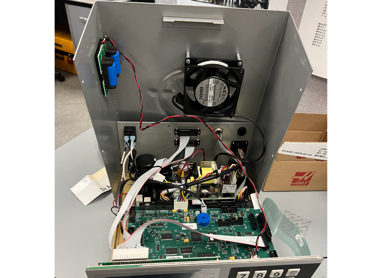
This procedure will show you how to replace the batteries on a Servo Control Box.

Warning: The Rotary Servo Control box will not work properly without the batteries.  These batteries are used by the control to retain the rotary servo control configuration parameters and programs.

Parts Required:

  • Lithium Battery (Qty: 2) (see note for sourcing instructions)

NOTE: To determine which battery to source please refer to our Lithium Battery Reference Guide

Battery Installation

Remove the SHCS using a 7/64 allen key that hold the cover of the rotary box.

Note: Be careful with the rotary box fan cable and external battery cable.


Remove the clips on the external battery board [1].

Install the batteries and place the clips back around the batteries as they were found originally.

  • The external battery board is mounted on the side of the cover using Velcro and can be removed from the Velcro to make installing the batteries easier.  
  • Reinstall the cover and verify the rotary control box functions properly

Refer to the How to Initialize Servo Control to Factory Default Parameters procedure.

6.6 Rotary - Backlash Testing

Recently Updated

Rotary - Backlash Testing


Revision A - 4/2025

Introduction

The document below provides a detailed explanation for finding backlash on a Haas Rotary unit.

Note: The following rotary units can not be checked for backlash HRT110, HRT210SHS, HRT160SS /210SS.


Backlash Test for HRT and HRC

Note: HRC units must be plugged, powered up, and disconnected from the air when checking backlash. 

Disconnect the air supply to the rotary.

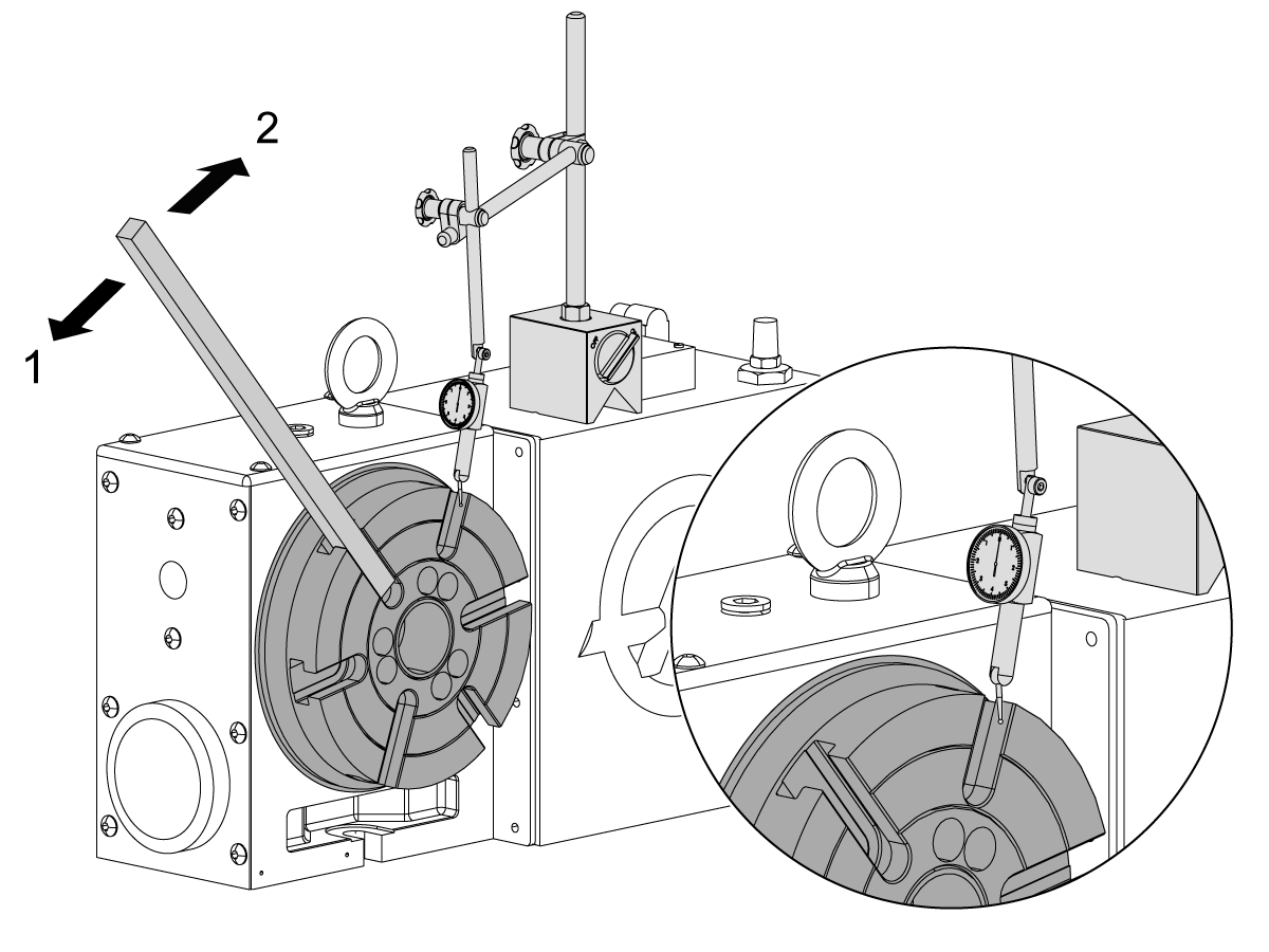
Put the dial indicator on the rotary as shown in the illustration.

Use an aluminum pry bar (approx. 1" X 1/2" X 18") to push down the spindle [1] at about 15 ft-lb (20 N-m), and then release. Set the indicator dial to 0.

Use the pry bar to push up the spindle [2] at about 15 ft-lb (20 N-m), and then release.

If the indicator shows more than 0.0005" (0.01 mm), the adjustment of the spindle backlash is necessary.

For this adjustment you must send the rotary to a certified rotary repair facility.

For instructions on where to find a rotary repair facility and how to send your rotary unit, go to  www.haascnc.com.


Backlash Test for Trunnions

A / B Axis

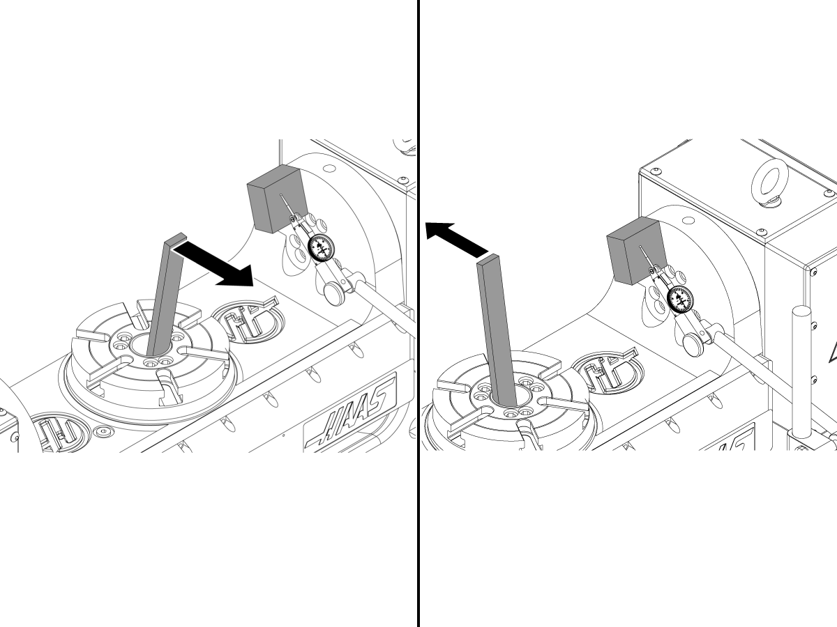
Place a flat rectangular magnet on the flat part of the TR as shown in the picture. The flat side that will be used to measure backlash should be pointed to the center of rotation of the axis. 

Set the tip of the dial indicator on the flat surface of the magnet as shown in the picture. Pull the bar three times to get the gear teeth fully engaged in one direction and set the dial gage to zero. 

Push the bar in the opposite direction once and read the dial gage. It will show the amount of backlash. 

C Axis

Disconnect the air supply to the rotary.

Put the dial indicator on the rotary as shown in the illustration.

Use an aluminum pry bar (approx. 1" X 1/2" X 18") to push down the spindle [2] at about 15 ft-lb (20 N-m), and then release. Set the indicator dial to 0.

Use the pry bar to push up the spindle [2] at about 15 ft-lb (20 N-m), and then release.

If the indicator [1] shows more than 0.0005" (0.01 mm), the adjustment of the spindle backlash is necessary.

For this adjustment you must send the rotary to a certified rotary repair facility.

For instructions on where to find a rotary repair facility and how to send your rotary unit, go to  www.haascnc.com.

Backlash Test for TRT

A Axis

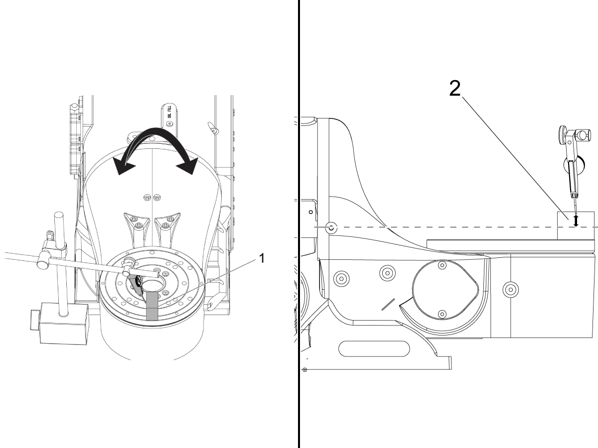
Place a magnetic block on the front of the TRT platter as shown in the following image. 

Place the dial gauge tip on side of the block's machined surface. [1]

Note: Measure how far the tip of the indicator is to the  A -Axis of rotation [2].

Zero the indicator, then move the A axis towards the indicator (.001). This will allow enough rotation to engage the gears in one full direction. 

Important: Write down the initial measurement found of the dial indicator as this value will be used later. 

Select the smallest increment (.0001) and move away from the indicator 10 times.

Note: Backlash value will be the difference from the starting measurement subtracted by the final position found on the dial indicator. 

B Axis

Place a magnetic block on the front of the TRT platter as shown in the following image. 

Place the dial gauge tip on side of the block's machined surface. [1]

Note: Measure how far the tip of the indicator is to the  B -Axis of rotation [2].

Zero the indicator, then move the B - Axis towards the indicator (.001). This will allow enough rotation to engage the gears in one full direction. 

Important: Write down the initial measurement found of the dial indicator as this value will be used later. 

Select the smallest increment (.0001) and move away from the indicator 10 times.

Note: Backlash value will be the difference from the starting measurement subtracted by the final position found on the dial indicator. 

Calculating Arc Seconds

The backlash tolerance on rotaries is given in arc seconds. The equation to calculate arc seconds is a=(1,296,000*b)/(2*pi*r). Where; a=arcseconds, b=backlash, r=radius of measured arc and pi=3.14. 

The total backlash tolerance is plus or minus 30 arc-seconds. 

   Base to A axis [2] Rim to B Axis [1]
TRT100 .88 from platter 2.0 in (50 mm)
TRT160 1.66 3.2 in (80 mm)
TRT210 1.4 4.6 in (115 mm)
TRT310 1.93 in 6.1 in (155 mm)

Note: The TRT 100 can be back driven so it needs to be plugged into power and disconnected to air. 

6.6 Rotary Belt Tension

Introduction

This procedure will show you how to find the belt tension specification of a rotary unit.

Tools Required:

  • T-0039A Sonic Belt Tension Meter 

Setup Procedure

1

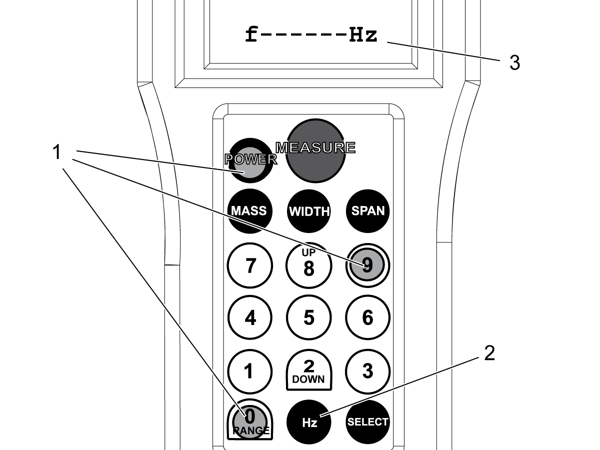
Change the units to lbf, as follows:

  • Hold [0] and [9] and push [POWER] at the same time [1].
  • Push [SELECT] again and again until the display shows lbf.
  • Hold [POWER] until the power goes off.
  • Push [POWER] to start the meter.

To show Hz in the display , push [HZ] [2] again and again until the display shows Hz [3].

Operating Procedure

1

Refer to the chart below to find the specified setting number that correlates with the correct rotary unit. Once the setting number has been selected, the number will be displayed and the tool will be ready to test.

Rotary Model Setting Number Width Span Belt Tension Range(LBS) Belt Tension(N)
Units N/A MM MM LBS N
HRT100 0 15 45 25-30 100-125
HRT160 1 15 90 45-55 195-235
HRT210 2 15 109 40-50 185-230
HRT310 3 15 148 65-80 295-360
HRT450 4 15 260 80-100 365-445
HRT600 5 15 270 80-100 365-445
HRT630 6 25 151 140-170 615-750
HRT800 6 25 151 140-170 615-750
HRT1000 6 25 151 140-170 615-750
HRT160SP 7 15 170 45-55 195-235
HRT210SP 8 15 202 40-50 185-230
HRY310SP 9 15 280 65-80 295-360
HRT160-2 1 15 90 45-55 195-235
HRT210-2 10 15 120 40-50 185-230
HRT210HT 2 15 109 40-50 185-230
HRT160SS 11 15 164 40-50 185-230
HRT210SS 12 15 185 25-30 110-135
HRT310ss 13 15 237 80-100 360-440
TR160 4th AXIS 11 15 164 40-50 185-230
TR210 4th AXIS 14 15 225 80-100 365-445
TR310 4th AXIS 15 15 212 140-170 615-750
TR160 5th AXIS 16 15 124 45-55 195-235
TR210 5th AXIS 17 15 137 40-50 185-230
TR310 5th AXIS 11 15 164 65-80 295-360
TR160-2 5th AXIS 9 15 280 45-55 195-235
TR200Y 5th AXIS 12 15 185 40-50 185-230
TRT160 4thAXIS 2 15 109 40-50 185-230
TRT160 5th  AXIS 18 15 68 50-60 220-270
TRT210 4th AXIS 3 15 148 80-100 365-445
TRT210 5th AXIS 19 15 102 50-60 220-270
TRT310 4th AXIS  8 15 202 65-80 295-360
TRT310 5th AXIS 7 15 176 65-80 295-360
TH240 3 15 148 80-100 365-445
TH450 8 15 202 65-80 295-360

2

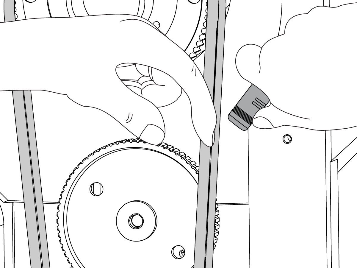
Position the sensor within 3/8” of the belt, about mid-span.

Pluck the belt to induce a vibration. .

The displayed value is the amount of tension in that span of the belt. 


Note: If the test is out of range from the chart provided, a re-test will need to be conducted. 

TRT Retest Procedure

1

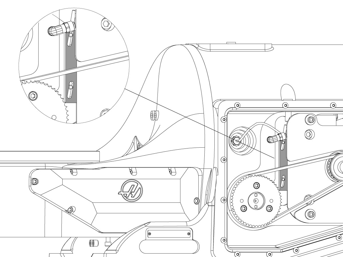
Detach the side panel on the tilt casting to access the necessary components.

On an TRT Unit loosen the set screw.

The spacer can be pushed up to tighten the belt or down to loosen it. 

2

Remove the under panel of the rotary casting to expose the motor spacer.


3

Remove the left side panel of the rotary casting to expose the belt [3].

Loosen the set screw located on the motor spacer. Slide the spacer to the left to decrease tension. Slide the spacer to the right to increase tension. 

Torque down the set screw and retest by vibrating the belt. 

HRT Retest Procedure

1

Remove the servo cable and the surrounding housing panels. 

 Loosen the set screw.


2

On the opposite side of the setscrew, the spacer can be pushed either to right to allow the belt to be tightened or pulled to the left to loosen the belt. 

Torque down the set screw and retest by vibrating the belt. 


Recently Viewed Items

You Have No Recently Viewed Items Yet

Feedback
Haas Logo

Haas Delivered Price

This price includes shipping cost, export and import duties, insurance, and any other expenses incurred during shipping to a location in France agreed with you as a buyer. No other mandatory costs can be added to the delivery of a Haas CNC Product.

KEEP UP WITH THE LATEST HAAS TIPS AND TECHNOLOGY...

Sign up now!   

HAAS TOOLING ACCEPTS THE FOLLOWING:

  • Service & Support
  • Owners
  • Request Service
  • Operator Manuals
  • Haas Parts
  • Rotary Repair Request
  • Pre-Install Guides
  • Shopping Tools
  • Build & Price a New Haas
  • Available Inventory
  • The Haas Price List
  • CNCA Financing
  • About Haas
  • Accessibility Statement
  • DNSH Statement
  • Export Compliance
  • Careers
  • Certifications & Safety
  • Contact Us
  • History
  • Terms & Conditions
  • Haas Tooling Terms & Conditions
  • Privacy
  • Warranty
  • Haas Community
  • Haas Certification Program
  • Haas Motorsports
  • Gene Haas Foundation
  • Haas Technical Education Community
  • Events
  • Join the Conversation
  • Facebook
  • X
  • Flickr
  • YouTube
  • LinkedIn
  • Instagram
  • TikTok
© 2026 Haas Automation, Inc – CNC Machine Tools

This site is protected by reCAPTCHA and the Google Privacy Policy and Terms of Service apply.

2800 Sturgis Rd., Oxnard, CA 93030
Toll Free: (888) 817-4446 / Fax: 805-278-8554