My Haas Welcome,
!
Haas Tooling MyHaas/HaasConnect Sign In Register Haas Tooling MyHaas/HaasConnect Sign Out Welcome, My Machines Latest Activity My Quotes My Account My Users Sign Out
Find Your Distributor
  1. Select Language
    1. English
    2. Deutsch
    3. Español - España
    4. Español - México
    5. Français
    6. Italiano
    7. Português
    8. Český
    9. Dansk
    10. Nederlands
    11. Magyar
    12. Polski
    13. Svenska
    14. Türkçe
    15. 中文
    16. Suomi
    17. Norsk
    18. الإنجليزية
    19. български
    20. Hrvatski
    21. Ελληνικά
    22. Română
    23. Slovenský
    24. Slovenščina
    25. 한국어
    26. 日本語
    27. Українська
  • machines Main Menu
    • Vertical Mills
      Vertical Mills
      Vertical Mills View All
      • Vertical Mills
      • VF Series
      • Universal Machines
      • VR Series
      • VP-5 Prismatic
      • Pallet-Changing VMCs
      • Mini Mills
      • Mold Machines
      • High-Speed Drill Centers
      • Drill/Tap/ Mill Series
      • Toolroom Mills
      • Pocket Mill
      • Compact Mills
      • Gantry Series
      • SR Sheet Routers
      • Extra-Large VMC
      • Double-Column Mills
      • 3+2 Positioning Machines
    • Multi-Axis Solutions
      Multi-Axis Solutions
      Multi-Axis Solutions View All
      • Multi-Axis Solutions
      • Y-Axis Lathes
      • 5-Axis Mills
    • Lathes
      Lathes
      Lathes View All
      • Lathes
      • ST Series
      • Dual-Spindle
      • Box Way Series
      • Toolroom Lathes
      • Chucker Lathe
      • Haas Bar Feeders
    • Horizontal Mills
      Horizontal Mills
      Horizontal Mills View All
      • Horizontal Mills
      • 50-Taper
      • 40-Taper
    • Rotaries & Indexers
      Rotaries & Indexers
      Rotaries & Indexers View All
      • Rotaries & Indexers
      • Rotary Tables
      • Indexers
      • 5-Axis Rotaries
      • Extra-Large Rotaries
    • Special Series
      Special Series
      Special Series View All
      • Special Series
      • EU_Series_Redirect
    • Automation Systems
      Automation Systems
      Automation Systems View All
      • Automation Systems
      • Mill Automation
      • Lathe Automation
      • Automatic Parts Loaders
      • Automation Models
    • Desktop Machines
      Desktop Machines
      Desktop Machines View All
      • Desktop Machines
      • Desktop Mill
      • Desktop Lathe
      • Control Simulator, Standard
      • Control Simulator, Premium
    • Shop Equipment
      Shop Equipment
      Shop Equipment View All
      • Shop Equipment
      • Knee Mill
      • Haas Manual Lathes
      • Haas Saws
    • Fabrication Machines
      Fabrication Machines
      Fabrication Machines View All
      • Fabrication Machines
      • Laser Cutting Machines
      • CNC Press Brakes
    • QUICK LINKS Special Series  Special Series 
      EU SERIES EU SERIES BUILD & PRICE | PRICE LIST BUILD & PRICE | PRICE LIST In-Stock Machines In-Stock Machines WHAT’S NEW WHAT’S NEW YOUR FIRST CNC YOUR FIRST CNC
      SHOPPING TOOLS
      • Build & Price a Haas
      • Price List
      • Available Inventory
      • CNCA Financing
      WANT TO TALK TO SOMEONE?

      A Haas Factory Outlet (HFO) can answer your questions, and walk you through your best options.

      CONTACT YOUR DISTRIBUTOR >
  • Options Main Menu
    • The Haas Control Value Option Packages
      Value Option Packages
      Value Option Packages View All
      • Value Option Packages
    • Product Image Spindles
      Spindles
      Spindles View All
      • Spindles
    • Product Image Tool Changers
      Tool Changers
      Tool Changers View All
      • Tool Changers
    • Product Image 4th- | 5th-Axis
      4th- | 5th-Axis
      4th- | 5th-Axis View All
      • 4th- | 5th-Axis
    • Product Image Turrets & Live Tooling
      Turrets & Live Tooling
      Turrets & Live Tooling View All
      • Turrets & Live Tooling
    • Product Image Probing
      Probing
      Probing View All
      • Probing
    • Haas Chip & Coolant Management Chip & Coolant Management
      Chip & Coolant Management
      Chip & Coolant Management View All
      • Chip & Coolant Management
    • The Haas Control The Haas Control
      The Haas Control
      The Haas Control View All
      • The Haas Control
    • Product Image Product Options
      Product Options
      Product Options View All
      • Product Options
    • Product Image Tooling & Fixturing
      Tooling & Fixturing
      Tooling & Fixturing View All
      • Tooling & Fixturing
    • Product Image Workholding
      Workholding
      Workholding View All
      • Workholding
    • Product Image 5-Axis Solutions
      5-Axis Solutions
      5-Axis Solutions View All
      • 5-Axis Solutions
      • 5 Easy Steps to 5-Axis
    • QUICK LINKS Special Series  Special Series 
      EU SERIES EU SERIES BUILD & PRICE | PRICE LIST BUILD & PRICE | PRICE LIST In-Stock Machines In-Stock Machines WHAT’S NEW WHAT’S NEW YOUR FIRST CNC YOUR FIRST CNC
      SHOPPING TOOLS
      • Build & Price a Haas
      • Price List
      • Available Inventory
      • CNCA Financing
      WANT TO TALK TO SOMEONE?

      A Haas Factory Outlet (HFO) can answer your questions, and walk you through your best options.

      CONTACT YOUR DISTRIBUTOR >
  • Why Haas Main Menu
      Discover the Haas Difference
    • Why Haas
    • MyHaas
    • Education Community
    • Industry 4.0
    • Haas Certification
    • Customer Testimonials
  • Service Main Menu
      Welcome to Haas Service
      SERVICE HOME Operator’s Manuals How-To Procedures Troubleshooting Guides Preventive Maintenance Haas Parts Haas Tooling Videos
  • Videos Main Menu
  • Main Menu
    • View All
    • View All
    • View All
    • View All
      • HTEC Curriculum Support
      • Haas Value Option Packages (VOP) Journey
    • View All
      • Haas 10 kg Cobot Package
      • Cobot Kits
      • DC-1 Drill Center
      • CNC Sales News
      • Do More With Your Haas
    • View All
    • View All
      • contact-us-test
      • 4 - AUTOMATION SYSTEMS
      • Carousel-V2
      • expert test
      • Demo_Day_Trident-test
      • Link Test
      • image-sale-tag-test
      • article-list-test
      • Haas 25 kg Robot Package
      • test-algolia-page
    • View All
    • View All
    • View All
    • View All
      • calc-test
    • View All
    • QUICK LINKS Special Series  Special Series 
      EU SERIES EU SERIES BUILD & PRICE | PRICE LIST BUILD & PRICE | PRICE LIST In-Stock Machines In-Stock Machines WHAT’S NEW WHAT’S NEW YOUR FIRST CNC YOUR FIRST CNC
      SHOPPING TOOLS
      • Build & Price a Haas
      • Price List
      • Available Inventory
      • CNCA Financing
      WANT TO TALK TO SOMEONE?

      A Haas Factory Outlet (HFO) can answer your questions, and walk you through your best options.

      CONTACT YOUR DISTRIBUTOR >
  • Haas Tooling Main Menu
  • Haas Service Parts Main Menu

My Haas Welcome,
!
Haas Tooling MyHaas/HaasConnect Sign In Register Haas Tooling MyHaas/HaasConnect Sign Out Welcome, My Machines Latest Activity My Quotes My Account My Users Sign Out
Find Your Distributor
  1. Select Language
    1. English
    2. Deutsch
    3. Español - España
    4. Español - México
    5. Français
    6. Italiano
    7. Português
    8. Český
    9. Dansk
    10. Nederlands
    11. Magyar
    12. Polski
    13. Svenska
    14. Türkçe
    15. 中文
    16. Suomi
    17. Norsk
    18. الإنجليزية
    19. български
    20. Hrvatski
    21. Ελληνικά
    22. Română
    23. Slovenský
    24. Slovenščina
    25. 한국어
    26. 日本語
    27. Українська
×

Search Results

Web Pages

Images

    • <
    • 1
    • >

DC-Series - Tool Changer Motor Replacement - AD0835

Service Home How To Procedures DC-Series - Tool Changer Motor Replacement - AD0835

DC-Series - Tool Changer Motor Replacement - AD0835

- Jump to Section - 1. Introduction 2. Remove Tool Carousel Motor (7 steps) 3. Install Replacement Motor (4 steps) 4. Set TT-axis Alignment - Parameters 9.140 and 9.078 (9 steps) 5. Verify TT-axis Zero Position (3 steps) 6. Verify Tool Changer Alignment Back to Top
Recently Updated Last updated: 04/28/2025

DC-Series - Tool Changer Motor - Replacement


AD0835

Revision A - 04/2025

Introduction

This procedure shows how to replace the tool changer motor on all DC-series machines. The following service kits can be ordered to replace the tool changer motor:

  • 93-4832 - DC-1/2 - 30T TC Motor With Brake
  • 93-4816 - DC-1/2 - 30T TC Motor With Brake

Note: 93-4832 contains only a brake motor. This should be ordered if replacing a brake servo motor with a new brake motor. If replacing a non-brake motor with a brake motor, order 93-4816.

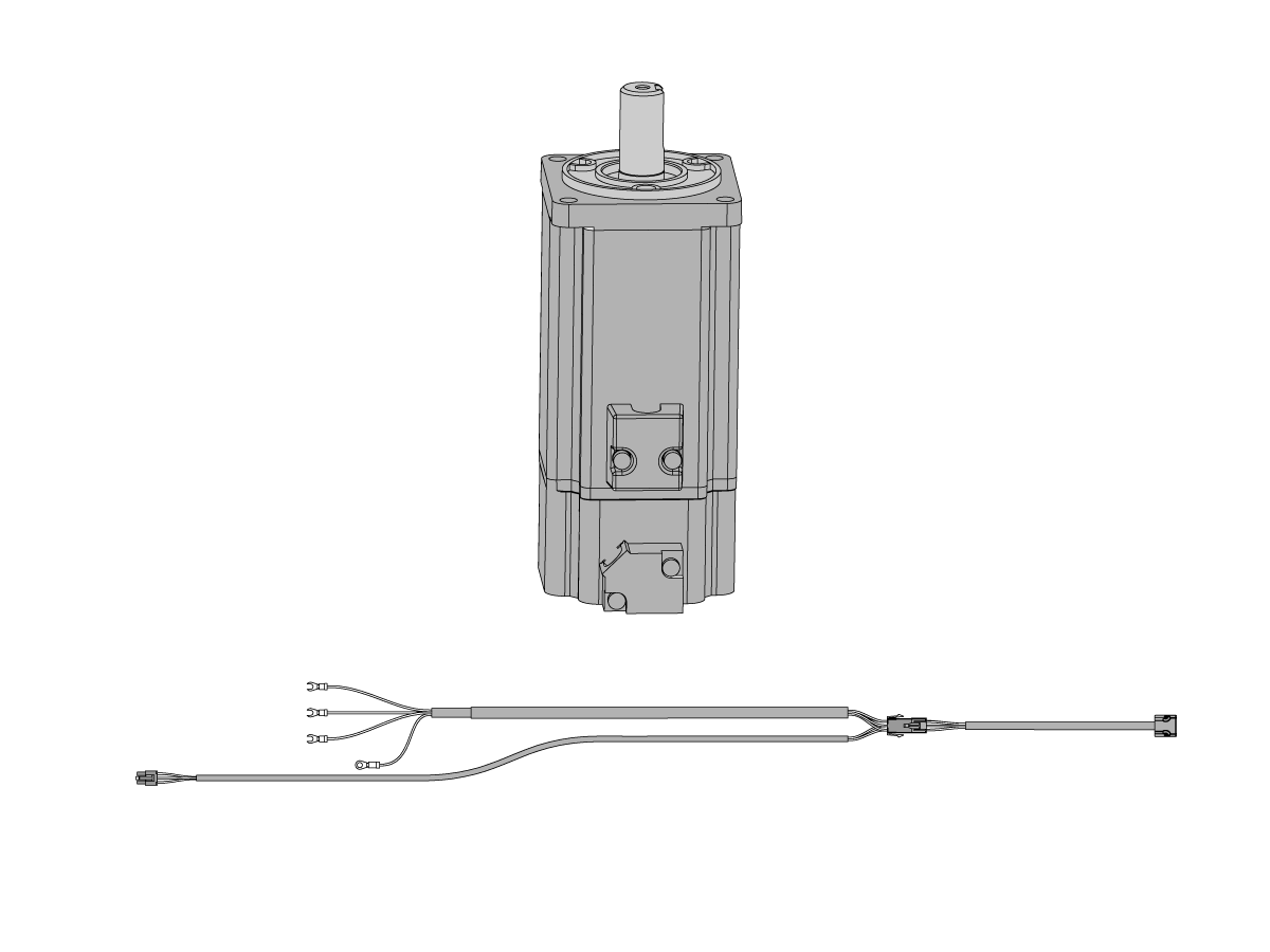
Note: To identify if the machine has a TC motor with or without a brake, you can look at the bill of materials of the machine, or visually inspect the cables coming from the motor. The cable in the image has a connection for the brake which indicates the motor is a brake motor.

Brake motors are part number 62-4445A and have a brake cable that connects to the IO PCB. Non-brake motors are part number 62-4445 and only have a power cable connected to the servo amplifier and an encoder cable connected to the Maincon PCB.

Remove Tool Carousel Motor

1

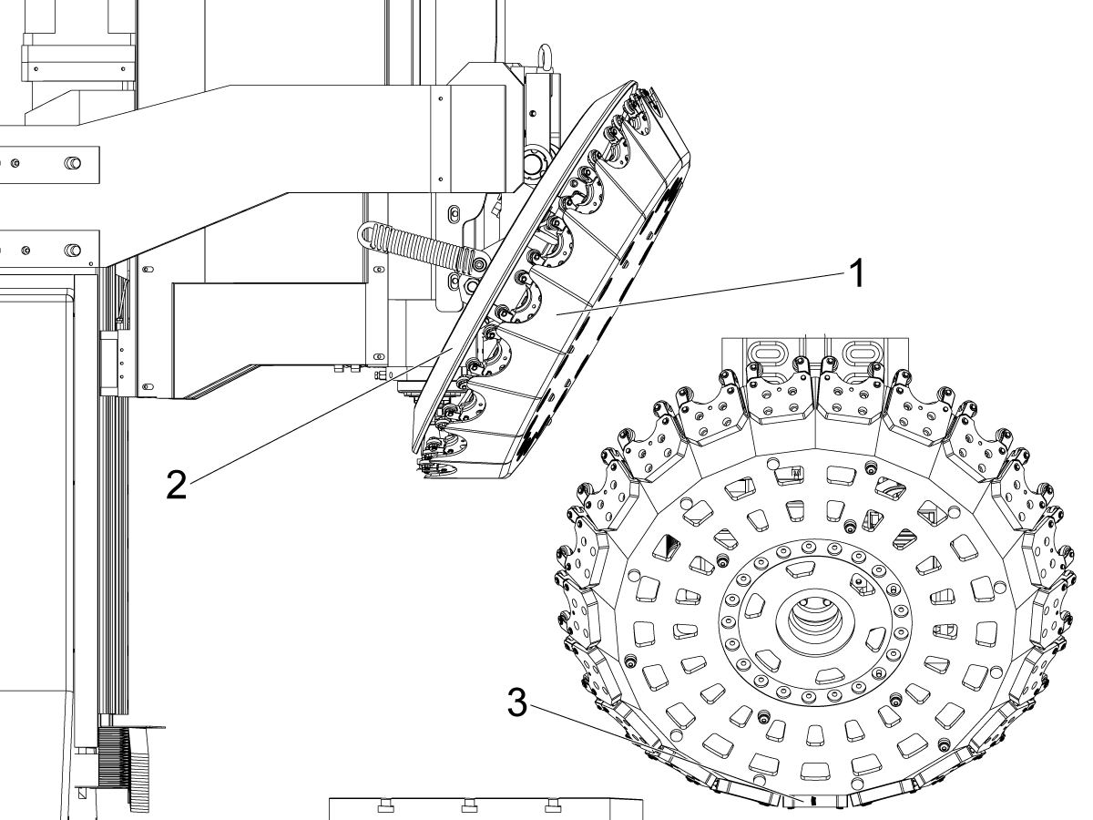
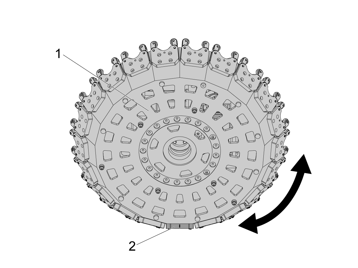
Remove both the front [1] and rear [2] cover from the tool carousel.

Note: Check that there is mark on pocket 1 so that it is clear how to orient the cover on the carousel when reinstalling the front cover.

2

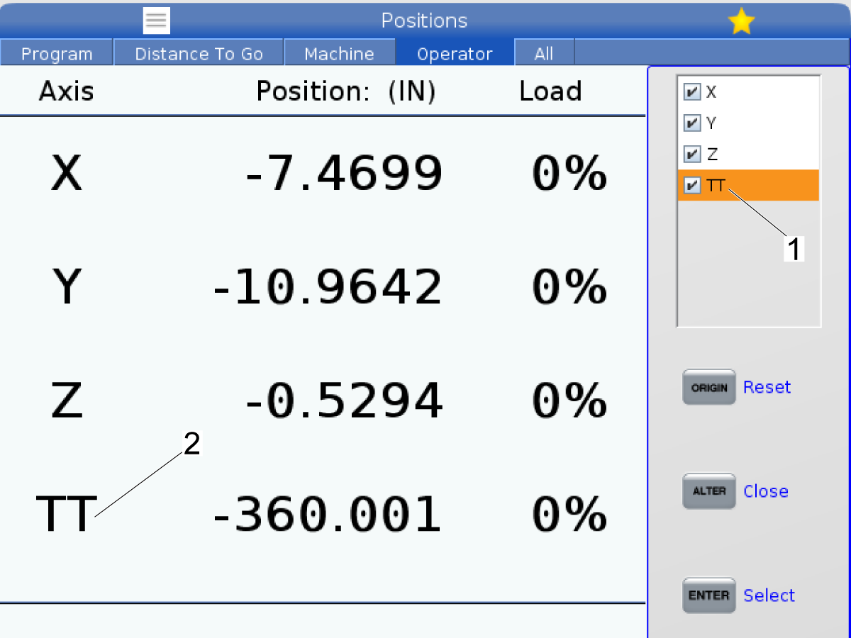
Make the TT-axis visible by changing parameter 9.019 - TT-axis Invisible to False.

Then press [Position] and then [Alter].

Highlight the TT-axis and press [Enter]. A check mark should appear next to the TT-axis.

Press [TT]+[Handle Jog] to jog the Tool carousel axis.

Continue to the next step. 

3

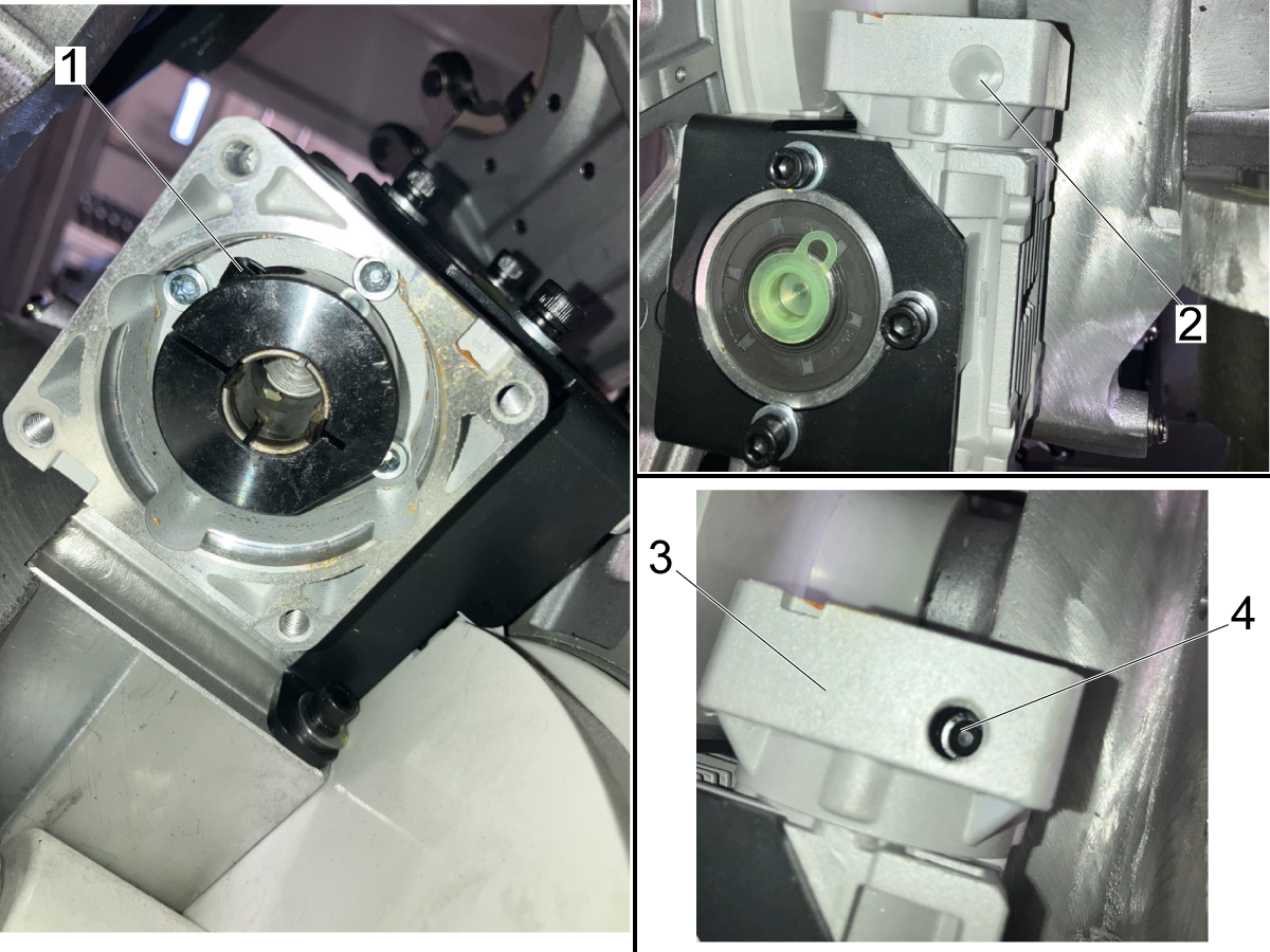
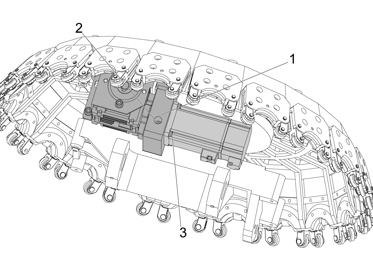
The shaft of the TT-axis motor is directly inside the gearbox for the TT-axis. The gearbox has a coupler that is friction fit to the shaft using a collar bolt.

Note: The motor is not shown in this image so that the gearbox and coupler can be seen.

To remove the motor, the collar bolt [1] on the motor coupler needs to be loosened.

Remove the plastic cover [2] from the top of the TT-axis gearbox [3] to use the access hole [4].

Note: Keep the plastic cover so that it can be reinstalled once the new motor is installed.

4

Jog the TT-axis until the collar bolt [1] is accessible through the hole in the gearbox [2].

The collar bolt needs to be fully aligned to the access hole so that you can loosen it. Continue jogging untill the hole is aligned as shown in the image on the right.

Use a metric hex head to access the bolt. Loosen the bolt so that the coupler is no longer clamped onto the motor shaft.

Note: The view in the images is from the top of the carousel looking down towards the table of the machine.

5

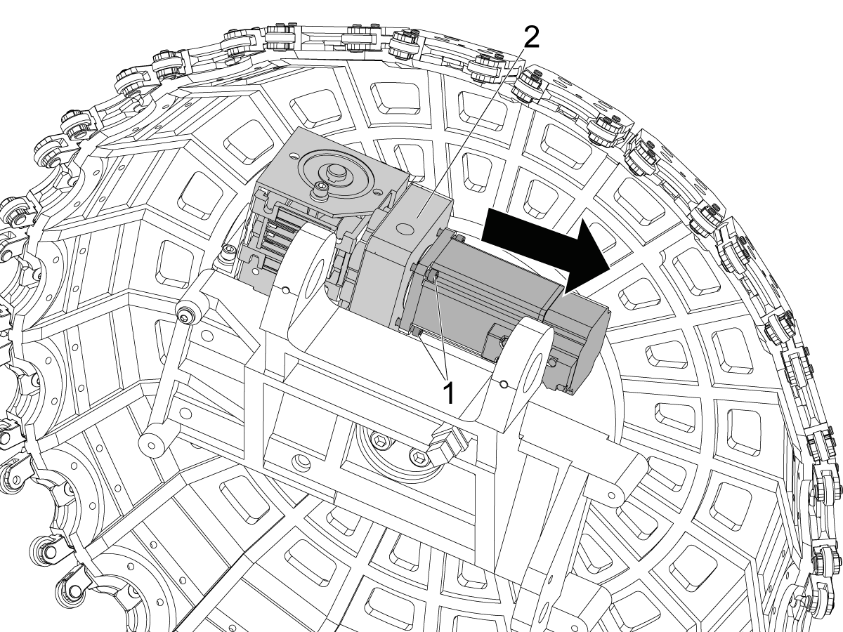
To remove the motor, unfasten the 4 mounting SHCS [1] holding the motor to the gearbox [2].

Once the SHCS are loosened about halfway, pull the motor away from the gearbox to verify that the shaft is free of the coupler. The motor should start to separate from the plate.

If you are replacing the motor power cable with the brake power cable, continue to the next steps before fully removing the motor.

If the power cable doesn't need to be removed, power off the machine and then disconnect both connectors from the motor [3] and continue to installing the new motor.

 Danger: Before beginning any work inside the control cabinet, verify that the High Voltage indicator light on the 320V Power Supply / Vector Drive has been off for a minimum of five (5) minutes. This waiting period ensures that residual voltage has dissipated and reduces the risk of electric shock.

Certain service procedures involve high-risk electrical components and may pose serious injury or fatality hazards. Technicians must not attempt any procedure unless they have a complete understanding of the steps involved and the associated risks.

If there is any uncertainty regarding a procedure, contact your Haas Factory Outlet (HFO) to arrange for a qualified service technician.

6

Important: The motor power cable only needs to be disconnected and unrouted if a non-brake motor is being replaced with a brake motor. This requires the new power cable to be installed. Skip to the next step if replacing a brake motor with a new brake motor.

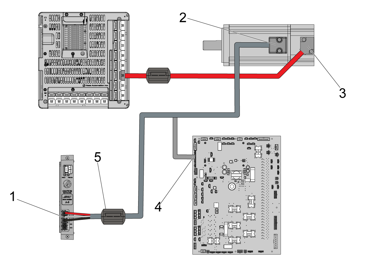
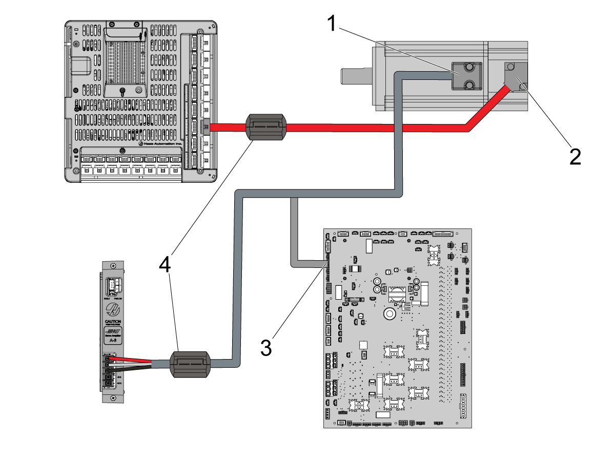
Disconnect the TT-axis power cable from the servo amplifier [1] and the motor end [2].

Disconnect the TT-axis encoder cable from the motor end [3].

Note: The encoder cable can be left routed to the tool changer since this cable is reused for the replacement motor.

Remove the power cable from the control cabinet since it will be replaced by the cable included in the replacement kit.

Note: Make sure that the ferrite filter [5] on the power cable is swapped to the new power cable.

Route the new power cable 32-1385 [4] through the control cabinet to the tool carousel motor.

7

For Machines Replacing Brake Motor With New Brake Motor:

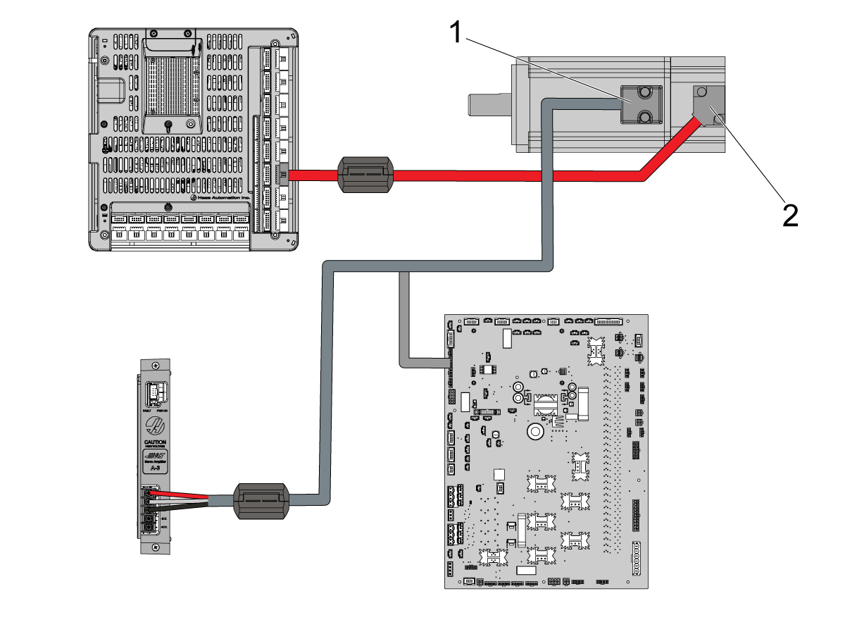
Disconnect the power cable [1] and the encoder cable [2] to the new motor.

These cables can be left routed since the same connections can be made on the replacement motor.

Install Replacement Motor

1

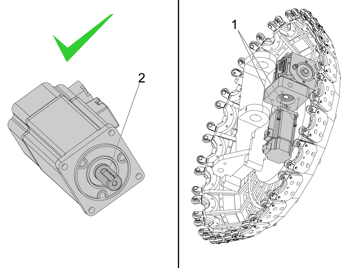
Remove the key from the motor shaft [2]. The gearbox coupler does not have a keyway.

Snug the 4 mounting SHCS [1] to hold the motor roughly in position.

Note: Do not fully tighten the mounting bolts at this time. This could create a misalignment between the motor shaft and the gearbox coupler.

2

Rotate the tool carousel [1] both clockwise and counterclockwise.

This will help align the motor shaft to the gearbox.

After rotating back and forth, rotate the carousel so that there is a pocket sitting roughly flat and inline with the spindle [2].

3

Use the access hole in the tool changer gearbox [1] to tighten the pinch bolt [2] on the gearbox coupler. 

If needed, rotate the carousel so that the pinch bolt lines up with the access hole.

Torque the pinch bolt to the required specification. The pinch bolt is an M6 x 1 so it should be torqued to 10 ft-lbs.

Cover the access hole on the gearbox with the plastic cover to prevent contaminants from getting in the gearbox

Note: If the replacement motor has a brake, the carousel will not be able to rotate by hand once the pinch bolt is tightened. 

Fully tighten the motor mounting bolts [3] after the motor shaft is clamped in the gearbox coupler.

Connect both the power cable and the encoder cable to the motor.

4

Now that the new motor is installed, connect both the power cable [1] and the encoder cable [2] to the new motor.

Make sure that the motor power cable is connected to ground, and that the ferrite filters [4] are installed properly on the encoder and power cable.

Note: Make sure that the cables are connected correctly in the electrical cabinet. For brake motors, ensure that the brake cable (integrated with the 32-1385 power cable) is connected to the IO PCB [3] at either of P3, P4, or P5.

Since the motor was replaced, the parameter values for the TT-axis need to be reset. Continue to the next section for how to set the offsets.

Set TT-axis Alignment - Parameters 9.140 and 9.078

To set the TT-axis alignment you need to set the values for parameters 9.140 - TT-axis Grid Offset and 9.079 - TT-axis Tool Change Offset.

Note: These parameters are only visible with a service key.

Start by setting the Factory parameters in the table below to the values listed.

Factory Setting Description Value
9.078 TT-axis Tool Change Offset 0 deg
9.140* TT-axis Grid Offset 0 deg

*If this parameter is already set to 0, change the value to 1 and then back to 0.

Before Starting TT-axis Alignment

Remove the front [1] and rear [2] covers of the tool carousel.

The front cover [1] is held in position by metric SHCS accessible from the front of the machine.

Note: When you remove the front cover make sure there is a mark on tool pocket 1 of the carousel. If there is not, mark the carousel [3] so you know how to orient the cover when it is reinstalled.

The rear cover is mounted by metric SHCS and the side windows of the machine may have to be removed to gain access to the screws. 

Remove all tools from the carousel. With the covers off you can remove tools from any pocket.

Warning: If there is a tool stuck in the spindle, it can only be removed by transferring it to the carousel pocket. Don't try and remove the tool from the spindle until you are confident that a pocket is going to grab the tool when the draw bar is released. Place something under the spindle to catch the tool in case it is dropped.

1

Before Starting TT-axis Alignment

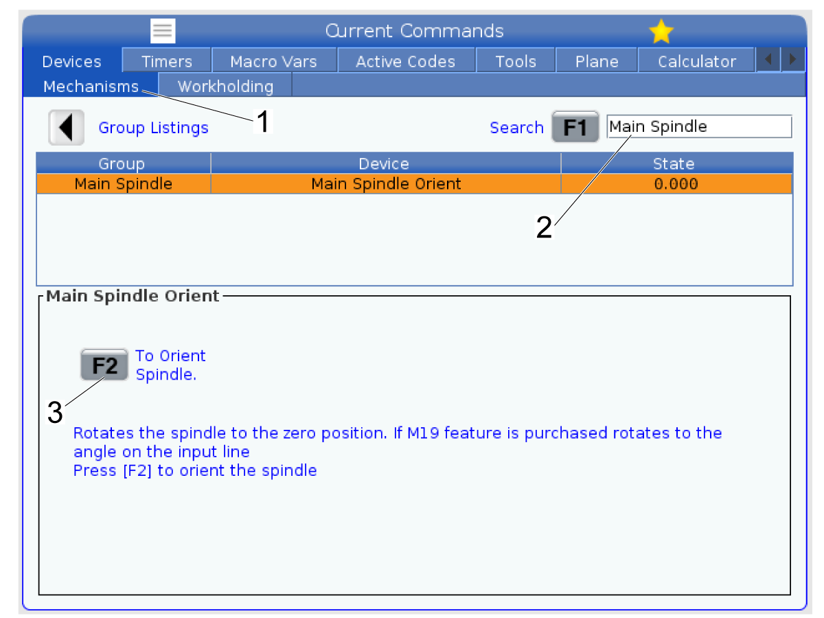
Press [Current Commands] and navigate to the Mechanisms [1] page inside of the Devices window.

Search for Main Spindle [2] and then press [F1] to search for it.

Press [F2] [3] to move the spindle to it's orientation offset based on it's spindle orientation offset parameter (30.085). Refer to the Set Spindle Orientation Offset section for how to set this parameter.

2

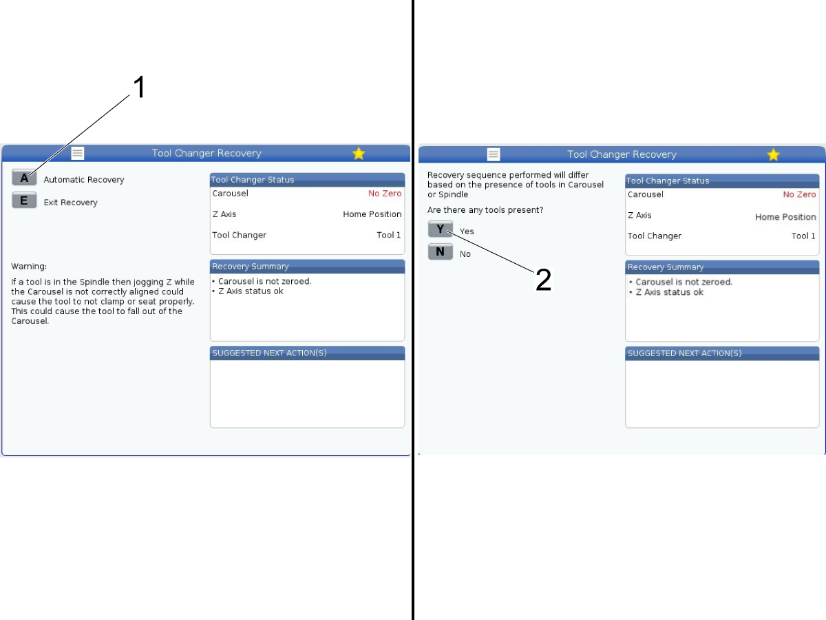
Once all tools are removed from the spindle and carousel start by pressing the [Recover] button on the Haas control to enter into Tool Changer Recovery.

Press [A] [1] for Automatic Recovery.

When asked "Are there any tools present" answer [N] [2] since all tools were removed in the previous step.

3

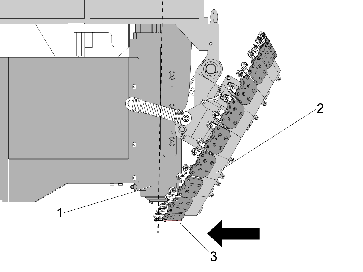
Press [Handle Jog] and jog the Z-axis up high enough so that the spindle [1] is above the carousel [2].

At this point the carousel will be pulled fully underneath the spindle as shown in the image. The Z-axis is high enough when the carousel no longer moves as you jog the Z-axis up.

The bottom of the pocket will be flat [3] once the spindle is high enough.

4

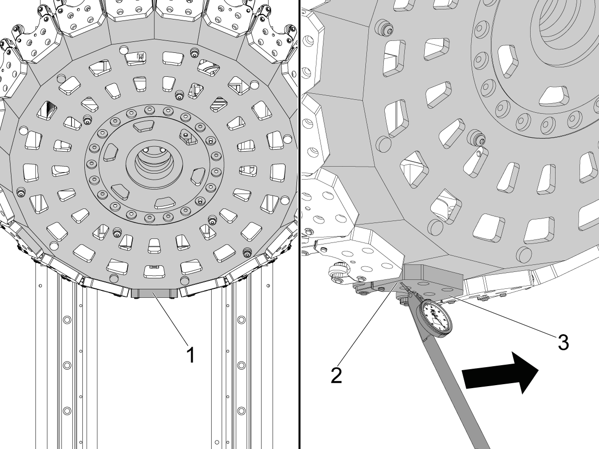
Jog the TT-axis so that pocket 1 is under the spindle is sitting flat parallel to the X-axis of the machine [1].

Put the mag base on the table and bring the indicator up to the pocket under the spindle.

Jog the X-axis so that the indicator moves across the bottom of the pocket from the left side [2] to the right side [3].

If the indicator shows more than 0.0005" difference from the left side of the pocket to the right, then jog the carousel so that the pocket is sitting flat.

Once there is less than 0.0005" difference between the edges of the pocket you can move to the next step.

5

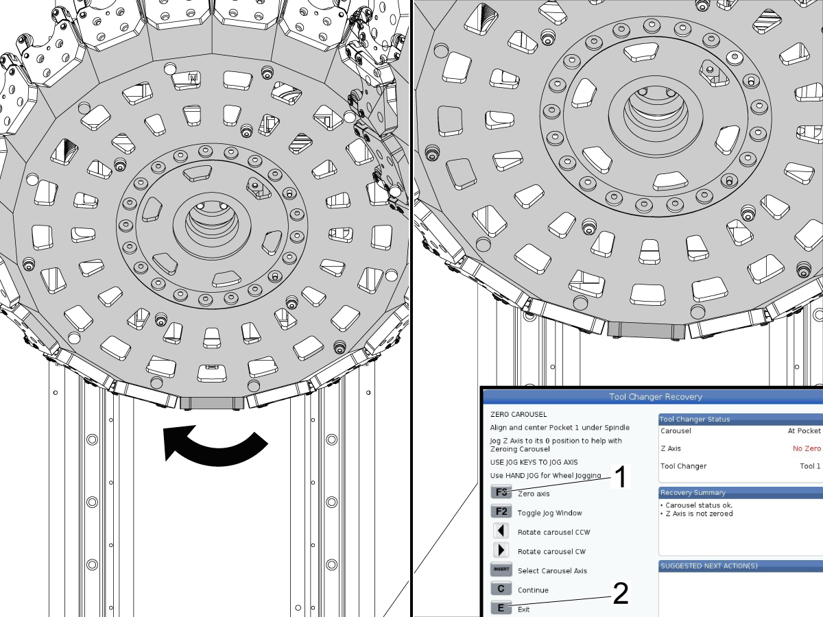
Jog the table away from the tool carousel so the indicator is clear of the tool carousel press the [Zero Return] button.

Press [F3] [1] to set the initial zero position for the TT-axis. 

When you press [F3] the carousel should rotate clockwise a few degrees. The tool pocket will no longer be sitting parallel with the X-axis. This is expected.

Press [E] [2] twice to exit recovery.

6

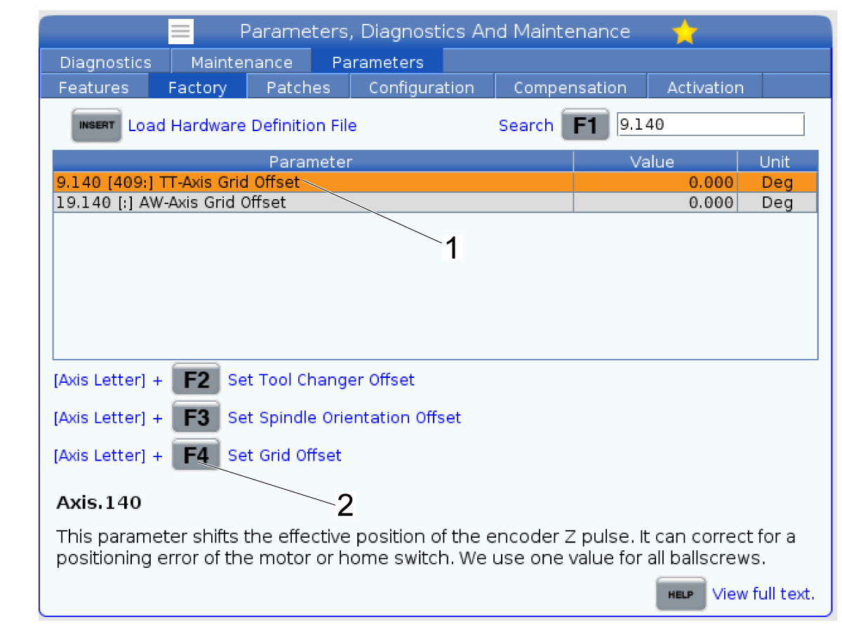
Keep the Carousel in the same position.

Navigate to the Factory tab in the Parameters window.

Search for parameter 9.140 - TT-axis Grid Offset.

Highlight the parameter [1] and press [TT] + [F4] [2] to set the parameter.

Press [Y] to confirm setting the parameter. The value should populate for the parameter.

Note: The carousel should not have been moved from the position it moved to in the previous step.

7

Go back into recovery and answer the questions until you get to the screen shown in the image.

Press [F2] to switch to jog mode. Jog the TT-axis so that the pocket in line with the spindle is sitting flat. 

Note: You do not need to indicate the pocket at this time to make sure it is within 0.0005" from one side to the other. Jog the TT-axis so that the pocket visually looks flat as shown in the image.

Once the pocket face looks flat, press [F2] [1] to switch back to recover mode and then press [F3] [2] to set the zero position for the TT-axis. 

The carousel will rotate clockwise and then rotate back slightly counterclockwise.

Press [F2] [1] to toggle back to jog mode.

8

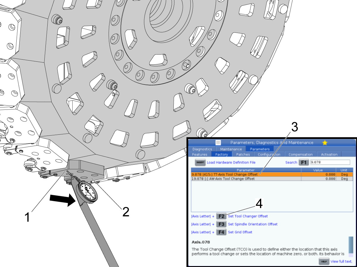
Jog the TT-axis so that the pocket under the spindle is sitting flat.

Use the indicator and sweep from the left side of the pocket [1] to the right side [2].

Jog the TT-axis until the pocket is flat within 0.0005" on the left and right sides.

Once you have the pocket in line with the spindle flat, press [E] twice to exit recovery.

Go to the factory tab in parameters and search for parameter 9.078 - TT-axis Tool Change Offset [3].

Highlight the parameter and then press [TT] + [F2] [4] to set the parameter value. The value should populate for the parameter.

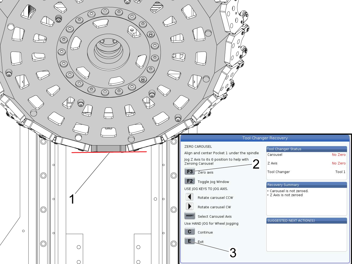
9

Since you just changed the offset value you need to set the zero position for the TT-axis again.

Press [Recover] to go into recovery. Answer the questions until you get to the page shown in the image to set the carousel zero position.

Visually check that the bottom of pocket 1 looks flat [1].

Note: The carousel should be flat since it is still in the same position as where you set the offset in the previous step. You shouldn't have to jog the carousel.

Press [F3] [2] to set the zero position for the carousel. The carousel will rotate clockwise, but then will rotate back counterclockwise to the position you set as the zero position.

Press [E] [3] twice to exit recovery.

Verify TT-axis Zero Position

1

Make sure the spindle is in it's orientation offset position.

To do this, press [Current Commands] and go to the Devices tab and then the Mechanisms window [1].

Type "Main Spindle" and then press [F1] [2] to search for the Main Spindle Orient.

Press [F2] [3] to move the spindle to it's orient position.

2

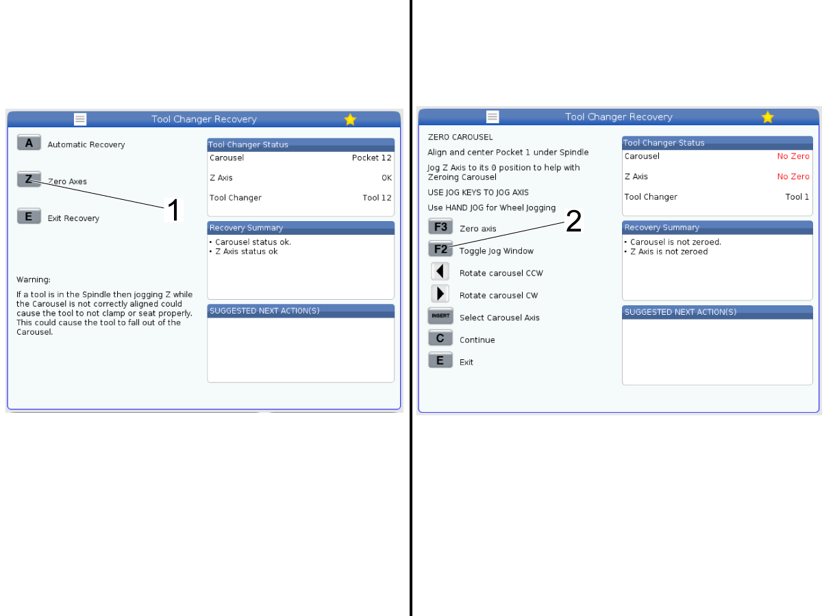
Press the [Recover] button to go into recovery.

Press [Z] [1] to go into the Zero Axes page.

Note: Use the Zero Axes option since we are just going to be jogging the Z-axis up and down. If you are not in recovery you cannot jog the Z-axis above it's zero position.

Answer the questions until you get to the Zero Carousel page that is shown in the image.

Press [F2] [2] so that you can jog the Z-axis.

Note: Do not jog the TT-axis, make sure to keep the TT-axis at it's zero position.

Select the Z-axis to jog and continue to the next step.

3

Start with the Z-axis above the carousel as shown in the left image of the picture.

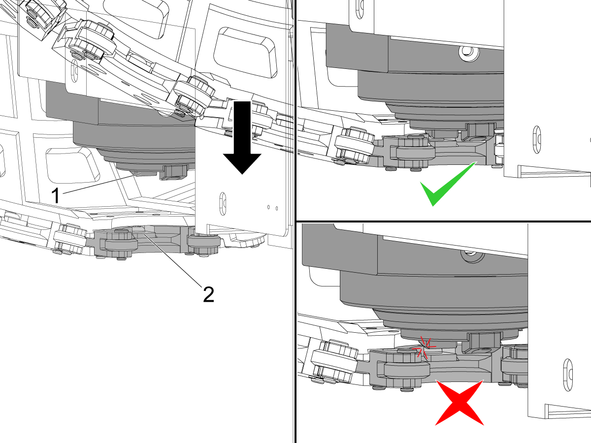
Jog the Z-axis down and watch to see how the spindle dog [1] engages with the tool pocket [2].

The dog should fit in the slot without contacting the edges of the pocket.

If the spindle dog does hit the edges, either the spindle orient is not parallel with the Y-axis or the TT-axis zero position is not parallel with the X-axis.

Use the indicator to determine if spindle or TT-axis needs to be adjusted. Refer to the sections above for how to adjust the parameters.

Note: While in recovery the spindle may rotate. Watch the first time the dogs meet the tool pocket to see the engagement. If you suspect the spindle dog rotated to self align, exit recovery and re-orient the spindle through Current Commands.

If the spindle dogs engage smoothly with the pocket and don't hit the edges then the TT-axis and spindle are aligned correctly. Press [E] twice to exit recovery.

Continue to setting the Z-axis alignment if needed.

Verify Tool Changer Alignment

Press [MDI] to enter MDI mode.

Press [5% Rapid] on the control so that you can closely monitor the test tool changes. 

Press [ATC FWD] to do a test tool change without any tools being loaded into the spindle. 

Listen for the sound the carousel makes as it does the tool change. If it doesn't sound excessively loud increase the speed to 25% rapid, then 50%, and then 100%.

Load a tool into the side pocket of the carousel. 

In MDI mode, press [ATC FWD] until the pocket holding the tool is next.

Important: Change the rapid on the machine to 5% before loading the tool into the spindle. Tool changes may sound good without a tool but the alignment could still be off causing rough tool changes with a tool. Change the rapid so you can E-STOP the machine if something doesn't look right.

While at 5% rapid, press [ATC FWD] to load the tool into the spindle. 

If the tool change sounds smooth, increase the rapid until you are doing tool changes at 100% rapid.

Important: Anytime you change the alignment for the TT-axis, Z-axis, or spindle orientation, you need to verify tool changes at 100% rapid at ALL tool pockets on the carousel.

Test loading a tool with each pocket starting at 25% rapid and then gradually increase the rapid until each tool pocket can load to the spindle at 100% rapid.

Recently Viewed Items

You Have No Recently Viewed Items Yet

Feedback
Haas Logo

Haas Delivered Price

This price includes shipping cost, export and import duties, insurance, and any other expenses incurred during shipping to a location in France agreed with you as a buyer. No other mandatory costs can be added to the delivery of a Haas CNC Product.

KEEP UP WITH THE LATEST HAAS TIPS AND TECHNOLOGY...

Sign up now!   

HAAS TOOLING ACCEPTS THE FOLLOWING:

  • Service & Support
  • Owners
  • Request Service
  • Operator Manuals
  • Haas Parts
  • Rotary Repair Request
  • Pre-Install Guides
  • Shopping Tools
  • Build & Price a New Haas
  • Available Inventory
  • The Haas Price List
  • CNCA Financing
  • About Haas
  • Accessibility Statement
  • DNSH Statement
  • Export Compliance
  • Careers
  • Certifications & Safety
  • Contact Us
  • History
  • Terms & Conditions
  • Haas Tooling Terms & Conditions
  • Privacy
  • Warranty
  • Haas Community
  • Haas Certification Program
  • Haas Motorsports
  • Gene Haas Foundation
  • Haas Technical Education Community
  • Events
  • Join the Conversation
  • Facebook
  • X
  • Flickr
  • YouTube
  • LinkedIn
  • Instagram
  • TikTok
© 2026 Haas Automation, Inc – CNC Machine Tools
This site is protected by reCAPTCHA and the Google Privacy Policy and Terms of Service apply.

2800 Sturgis Rd., Oxnard, CA 93030
Toll Free: (888) 817-4446 / Fax: 805-278-8554