My Haas Welcome,
!
Haas Tooling MyHaas/HaasConnect Sign In Register Haas Tooling MyHaas/HaasConnect Sign Out Welcome, My Machines Latest Activity My Quotes My Account My Users Sign Out
Find Your Distributor
  1. Select Language
    1. English
    2. Deutsch
    3. Español - ES
    4. Español - MX
    5. Français
    6. Italiano
    7. Português
    8. Český
    9. Dansk
    10. Nederlands
    11. Magyar
    12. Polski
    13. Svenska
    14. Türkçe
    15. 中文
    16. Suomi
    17. Norsk
    18. الإنجليزية
    19. български
    20. Hrvatski
    21. Ελληνικά
    22. Română
    23. Slovenský
    24. Slovenščina
    25. 한국어
    26. 日本語
    27. Українська
  • machines Main Menu
    • Vertical Mills
      Vertical Mills
      Vertical Mills View All
      • Vertical Mills
      • VF Series
      • Universal Machines
      • VR Series
      • VP-5 Prismatic
      • Pallet-Changing VMCs
      • Mini Mills
      • Mold Machines
      • High-Speed Drill Centers
      • Drill/Tap/ Mill Series
      • Toolroom Mills
      • Pocket Mill
      • Compact Mills
      • Gantry Series
      • SR Sheet Routers
      • Extra-Large VMC
      • Double-Column Mills
      • 3+2 Positioning Machines
    • Multi-Axis Solutions
      Multi-Axis Solutions
      Multi-Axis Solutions View All
      • Multi-Axis Solutions
      • Y-Axis Lathes
      • 5-Axis Mills
    • Lathes
      Lathes
      Lathes View All
      • Lathes
      • ST Series
      • Dual-Spindle
      • Box Way Series
      • Toolroom Lathes
      • Chucker Lathe
      • Pocket Lathe
      • Haas Bar Feeders
    • Horizontal Mills
      Horizontal Mills
      Horizontal Mills View All
      • Horizontal Mills
      • 50-Taper
      • 40-Taper
    • Rotaries & Indexers
      Rotaries & Indexers
      Rotaries & Indexers View All
      • Rotaries & Indexers
      • Rotary Tables
      • Indexers
      • 5-Axis Rotaries
      • Extra-Large Rotaries
    • Special Series
      Special Series
      Special Series View All
      • Special Series
      • EU_Series_Redirect
    • Automation Systems
      Automation Systems
      Automation Systems View All
      • Automation Systems
      • Mill Automation
      • Lathe Automation
      • Automatic Parts Loaders
      • Automation Models
    • Desktop Machines
      Desktop Machines
      Desktop Machines View All
      • Desktop Machines
      • Desktop Mill
      • Desktop Lathe
      • Control Simulator, Standard
      • Control Simulator, Premium
    • Shop Equipment
      Shop Equipment
      Shop Equipment View All
      • Shop Equipment
      • Knee Mill
      • Haas Manual Lathes
      • Haas Saws
    • Fabrication Machines
      Fabrication Machines
      Fabrication Machines View All
      • Fabrication Machines
      • Laser Cutting Machines
      • CNC Press Brakes
    • QUICK LINKS Special Series  Special Series 
      EU SERIES EU SERIES BUILD & PRICE | PRICE LIST BUILD & PRICE | PRICE LIST In-Stock Machines In-Stock Machines WHAT’S NEW WHAT’S NEW YOUR FIRST CNC YOUR FIRST CNC
      SHOPPING TOOLS
      • Build & Price a Haas
      • Price List
      • Available Inventory
      • CNCA Financing
      WANT TO TALK TO SOMEONE?

      A Haas Factory Outlet (HFO) can answer your questions, and walk you through your best options.

      CONTACT YOUR DISTRIBUTOR >
  • Options Main Menu
    • The Haas Control Value Option Packages
      Value Option Packages
      Value Option Packages View All
      • Value Option Packages
    • Product Image Spindles
      Spindles
      Spindles View All
      • Spindles
    • Product Image Tool Changers
      Tool Changers
      Tool Changers View All
      • Tool Changers
    • Product Image 4th- | 5th-Axis
      4th- | 5th-Axis
      4th- | 5th-Axis View All
      • 4th- | 5th-Axis
    • Product Image Turrets & Live Tooling
      Turrets & Live Tooling
      Turrets & Live Tooling View All
      • Turrets & Live Tooling
    • Product Image Probing
      Probing
      Probing View All
      • Probing
    • Haas Chip & Coolant Management Chip & Coolant Management
      Chip & Coolant Management
      Chip & Coolant Management View All
      • Chip & Coolant Management
    • The Haas Control The Haas Control
      The Haas Control
      The Haas Control View All
      • The Haas Control
    • Product Image Product Options
      Product Options
      Product Options View All
      • Product Options
    • Product Image Tooling & Fixturing
      Tooling & Fixturing
      Tooling & Fixturing View All
      • Tooling & Fixturing
    • Product Image Workholding
      Workholding
      Workholding View All
      • Workholding
    • Product Image 5-Axis Solutions
      5-Axis Solutions
      5-Axis Solutions View All
      • 5-Axis Solutions
      • 5 Easy Steps to 5-Axis
    • QUICK LINKS Special Series  Special Series 
      EU SERIES EU SERIES BUILD & PRICE | PRICE LIST BUILD & PRICE | PRICE LIST In-Stock Machines In-Stock Machines WHAT’S NEW WHAT’S NEW YOUR FIRST CNC YOUR FIRST CNC
      SHOPPING TOOLS
      • Build & Price a Haas
      • Price List
      • Available Inventory
      • CNCA Financing
      WANT TO TALK TO SOMEONE?

      A Haas Factory Outlet (HFO) can answer your questions, and walk you through your best options.

      CONTACT YOUR DISTRIBUTOR >
  • Why Haas Main Menu
      Discover the Haas Difference
    • Why Haas
    • MyHaas
    • Education Community
    • Industry 4.0
    • Haas Certification
    • Customer Testimonials
  • Service Main Menu
      Welcome to Haas Service
      SERVICE HOME Operator’s Manuals How-To Procedures Troubleshooting Guides Preventive Maintenance Haas Parts Haas Tooling Videos
  • Videos Main Menu
  • Main Menu
    • View All
    • View All
    • View All
    • View All
      • HTEC Curriculum Support
      • Haas Value Option Packages (VOP) Journey
    • View All
      • Haas 10 kg Cobot Package
      • Cobot Kits
      • DC-1 Drill Center
      • CNC Sales News
      • Do More With Your Haas
    • View All
    • View All
      • contact-us-test
      • 4 - AUTOMATION SYSTEMS
      • Carousel-V2
      • expert test
      • Demo_Day_Trident-test
      • Link Test
      • image-sale-tag-test
      • article-list-test
      • Haas 25 kg Robot Package
      • test-algolia-page
    • View All
    • View All
    • View All
    • View All
      • calc-test
    • View All
    • QUICK LINKS Special Series  Special Series 
      EU SERIES EU SERIES BUILD & PRICE | PRICE LIST BUILD & PRICE | PRICE LIST In-Stock Machines In-Stock Machines WHAT’S NEW WHAT’S NEW YOUR FIRST CNC YOUR FIRST CNC
      SHOPPING TOOLS
      • Build & Price a Haas
      • Price List
      • Available Inventory
      • CNCA Financing
      WANT TO TALK TO SOMEONE?

      A Haas Factory Outlet (HFO) can answer your questions, and walk you through your best options.

      CONTACT YOUR DISTRIBUTOR >
  • Haas Tooling Main Menu
  • Haas Service Parts Main Menu

My Haas Welcome,
!
Haas Tooling MyHaas/HaasConnect Sign In Register Haas Tooling MyHaas/HaasConnect Sign Out Welcome, My Machines Latest Activity My Quotes My Account My Users Sign Out
Find Your Distributor
  1. Select Language
    1. English
    2. Deutsch
    3. Español - ES
    4. Español - MX
    5. Français
    6. Italiano
    7. Português
    8. Český
    9. Dansk
    10. Nederlands
    11. Magyar
    12. Polski
    13. Svenska
    14. Türkçe
    15. 中文
    16. Suomi
    17. Norsk
    18. الإنجليزية
    19. български
    20. Hrvatski
    21. Ελληνικά
    22. Română
    23. Slovenský
    24. Slovenščina
    25. 한국어
    26. 日本語
    27. Українська
×

Search Results

Web Pages

Images

    • <
    • 1
    • >

VR H-5AX Spindle Head Replacement - AD0593

Service Home How To Procedures VR H-5AX Spindle Head Replacement - AD0593
Recently Updated Last updated: 03/04/2025

VR/GM H-5AX Spindle Head - Replacement

Revision 1


AD0593

VR H-5AX Spindle Head Replacement - AD0593

- Jump to Section - 1. Introduction 2. Removal of Spindle Head (5 steps) 3. Installation of Spindle Head (5 steps) 4. Setting the Tool Change Offset (1 step) 5. Setting Backlash Compensation (8 steps) 6. Complete an Inspection Report (1 step) Back to Top

Introduction

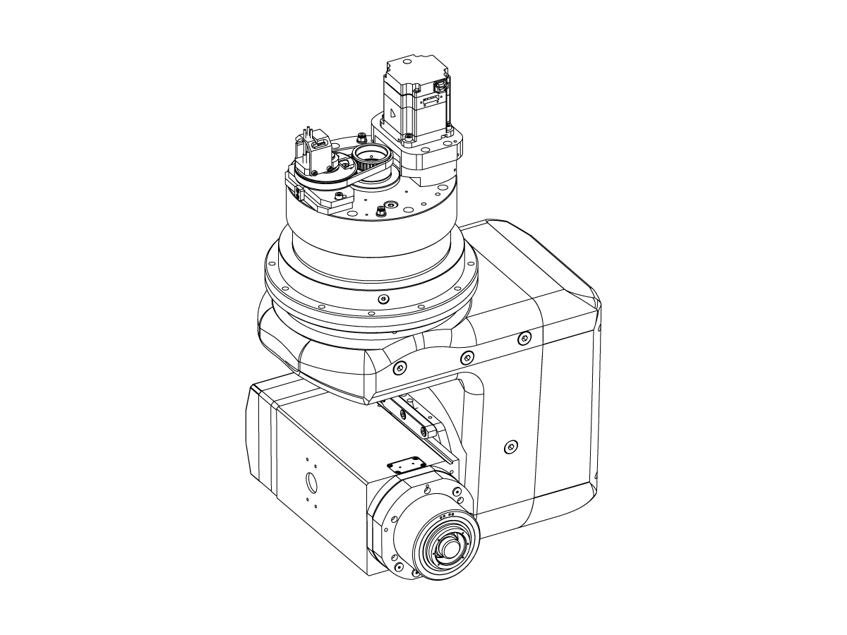
The following procedure describes how to replace the H-5AX spindle head on VR and GM Series machines.

Note:  To complete a H-5AX spindle head replacement requires the factory send the spindle head shipping bracket along with the replacement spindle head.

Tools Required:

  • T-0143 SHP BRKT HSD 5AX HEAD VR/GM

WARNING: It is important to verify and to go through the proper troubleshooting found in the H-5AX Spindle Head Troubleshooting guide and to fill out the H-5AX Service Request Form linked below before ordering a replacement head. 

H-5AX Service Request Form

This document applies to the following service kits:

  • 93-3586    HSD 5AX HEAD HSK A63 SIG 7 SVC
  • 93-3587    HSD 5AX HEAD HSK F63 SIG 5 SVC    
  • 93-3588    HSD 5AX HEAD HSK A63 SIG 5 SVC
  • 93-3589    HSD 5AX HEAD HSK F63 SIG 7 SVC  
  • 93-3590    HSD 5AX HEAD HSK F63 SIG 7 CLT SVC
  • 93-3591    HSD 5AX HEAD HSK A63 SIG 7 CLT SVC

Removal of Spindle Head

1

 Note: This procedure uses a VR for illustrative purposes. GM Machine will use this procedure as reference.

Return the B and C axis to its home position

Place a piece of cardboard on the machine table to avoid damaging the table during the removal/installation Process

Place the replacement spindle on one end of the table, on the other end leave space for the shipping bracket that will remove the current spindle.

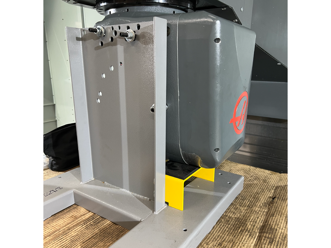
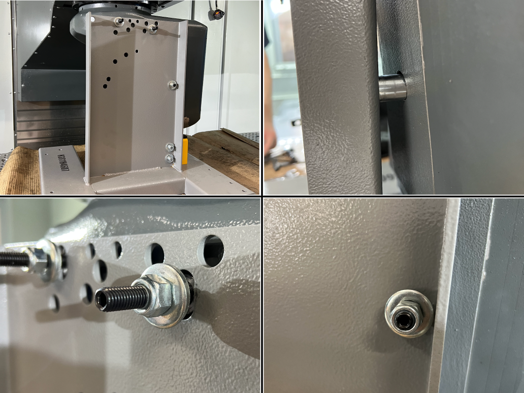
Place the H-5ax head shipping bracket on the empty side of the table on the machine, lower the spindle head onto the bracket. You will lower the spindle head until the spindle head is fully supported, this is indicated when the Z-axis load reaches 0-1%. 

2

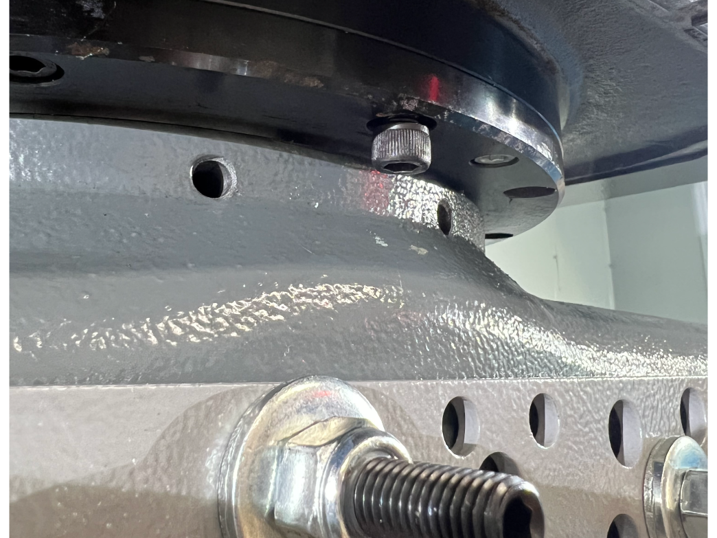
With the spindle fully supported use the hardware provided to mount the spindle head to the bracket.

3

With the spindle fully supported and mounted to the bracket remove the mounting bolts that attach the spindle to the spindle head casting.

Separate the spindle from the spindle head casting by raising the Z-axis, make sure the casting clears both servo motors on the replacement spindle and current spindle. Power off the machine. 

4

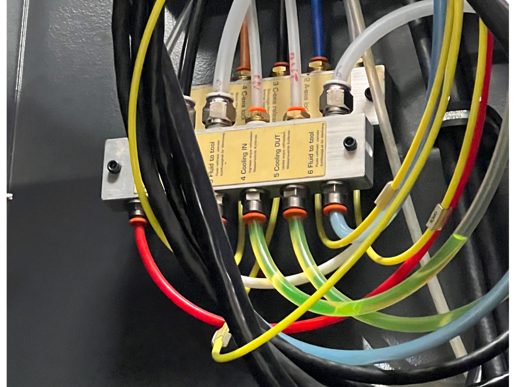
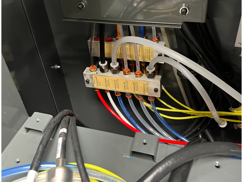
Remove the lines from the spindle head manifold located inside the spindle head enclosure. Take a picture and mark the lines so that when the new manifold is installed matching the lines to the correct port is easier. Disconnect the barrel connectors from the top of the machine as well.

5

Updated

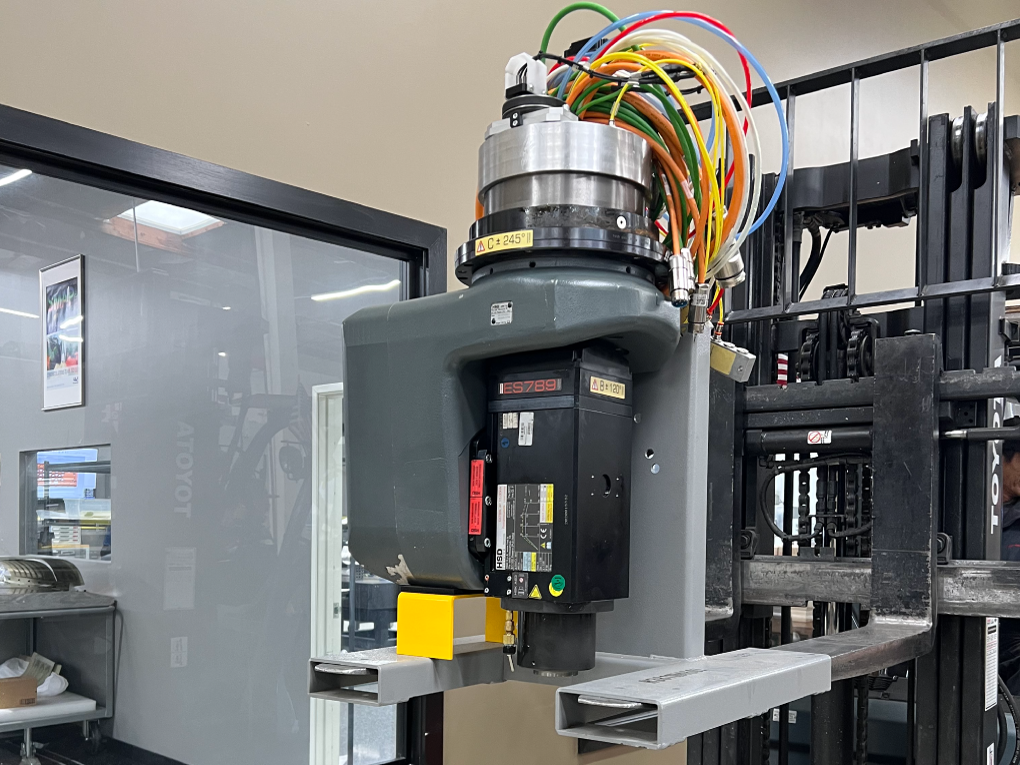
With all the wires and hoses unplugged use a forklift to move the old spindle head out of the machine and place the new spindle head into position. 

Note: Approximate weight of H-5AX Head Assembly:

H-5AX HEAD HSK A63 20K = 180 kg / 397 lbs 

H-5AX HEAD HSK F63  20K = 160 kg /  353 lbs

Installation of Spindle Head

1

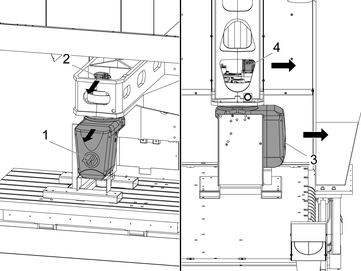
Slide the replacement spindle head under the casting in the position described below.

VR:

Make sure the Haas logo [1] on the spindle casting is facing the front of the machine, and that the servo motor [2] is oriented towards the front of the spindle head casting (see next step) or else the homing sequence may pose a problem later down the line if it is not. 

NOTE: The servo motor and Haas logo are usually positioned the same, in the event they are not, make sure the servo motor is located in the front of the casting regardless of the Haas logo.

GM:

Make sure the Haas logo [3] on the spindle casting is facing the operator side of the machine, and that the servo motor [4] is oriented towards the operator side or else the homing sequence may pose a problem later down the line if it is not. 

 NOTE: The servo motor and Haas logo are usually positioned the same, in the event they are not, make sure the servo motor is located towards the operators side of the machine, regardless of the Haas logo.

2

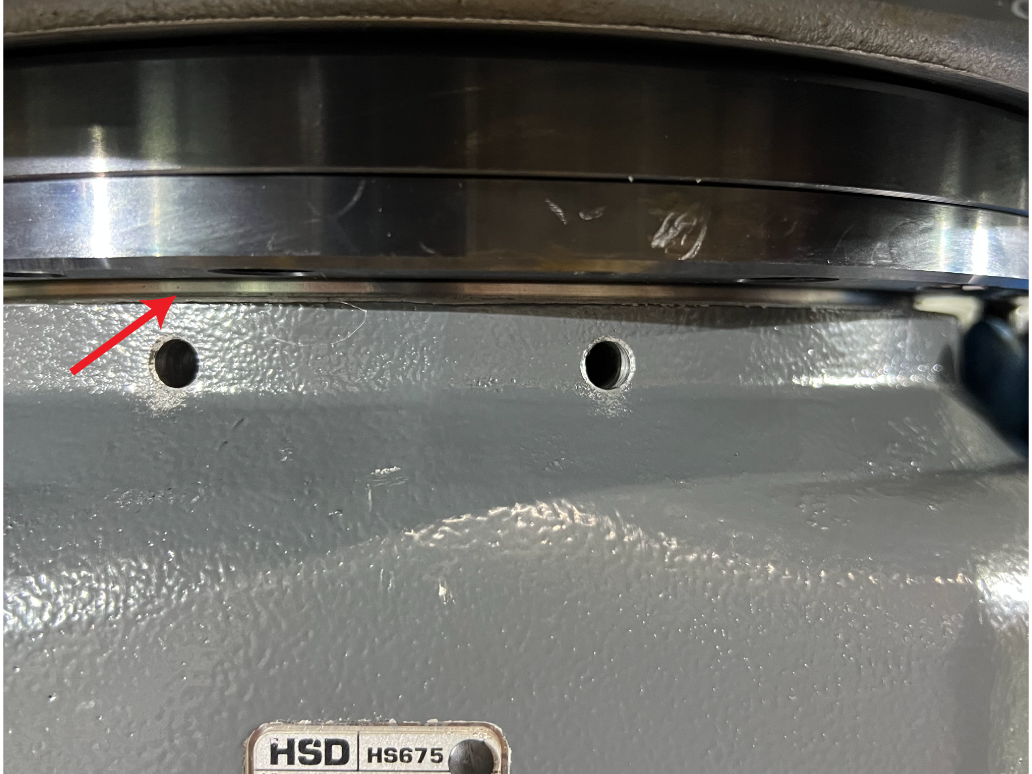
The spindle servo motor should be facing the front of the casting and the home switches located in the rear as seen in this image.

3

Plug all the hoses back into the manifold and plug all the barrel connector cables back to the using the pictures taken by the tech as reference. Neatly organize the hose and wires. 

4

With all the wires connected turn the machine back on, the spindle head originally sent with the machine may have been a sigma 5 motor and new motors use a sigma 7 motor.

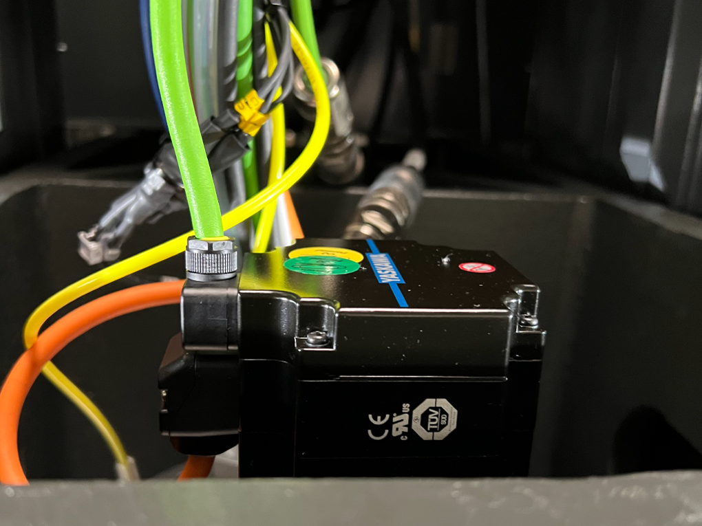
To verify which motor is in the machine check the motor on the top of the replacement spindle head.

Sigma 7 motors have a blue line across the top as shown in the image.

If the replacement motor and new motor are different, select the correct rotary configuration that reflects the motor in the replacement spindle head. 

Service Number

Description

B-Axis Parameter File

C-Axis Parameter File

93-3588

HSD 5AX HEAD HSK A63 SIG 5 SVC

VR-B-P11

VR-C-P11

93-3586

HSD 5AX HEAD HSK A63 SIG 7 SVC

63A-B-P18

63A-C-P18

93-3591

HSD 5AX HEAD HSK A63 SIG 7 CLT SVC

63A-B-P18

63A-C-P18

NOTE: Machine will require MRZP and Safe Zones to be redone if the machine has software version 100.21.000.100X and earlier 

5

With the correct configurations selected correct any alarms present and jog the spindle head casting down toward the new spindle. Setting 53 jog without zero return will need to be turned on to do so. DO NOT ZERO RETURN THE SPINDLE HEAD. Carefully jog the z axis down making sure the spindle is straight to avoid wedging the spindle into the spindle head bore. Bolt the plate to the casting. 

Setting the Tool Change Offset

1

Reset the grid offset, by zeroing parameters 6.140 B-AXIS GRID OFFSET and 7.140 C-AXIS GRID OFFSET and then zero returning each axis and pressing the axis B/C and pressing [F4].

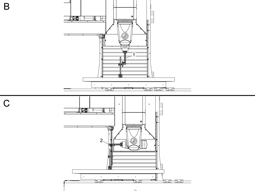
Set the Tool change offset for the B-Axis by sweeping the side of the test bar so it reads zero to zero over the entire length of the test bar [B].

Set the Tool change offset for the C-Axis by sweeping the front side of the test bar so it reads zero to zero over the entire length of the test bar [C].

NOTE: This is NTE 0.0005 in (0.0127 mm), but it is recommended to get this value as close to zero as possible. If the machine is experiencing issues getting it closer to zero, complete the backlash compensation section and return to set the tool change offset.

Setting Backlash Compensation

1

B-Axis Backlash

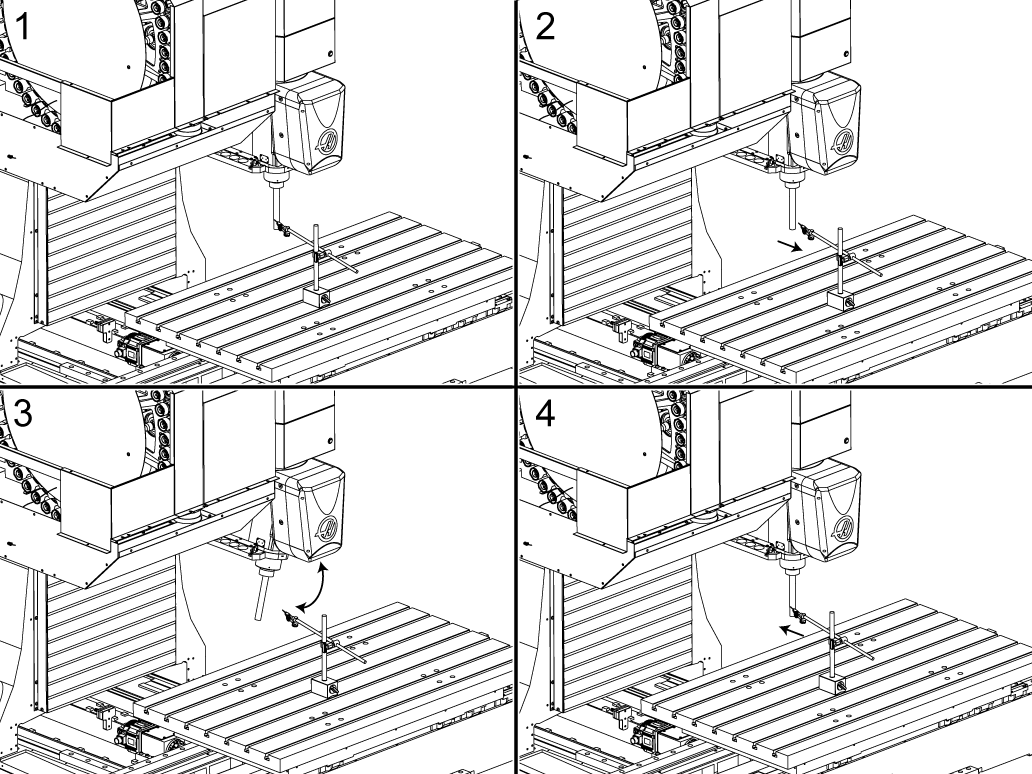
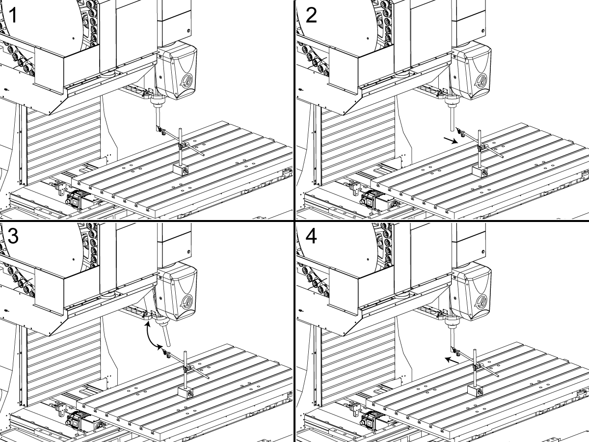
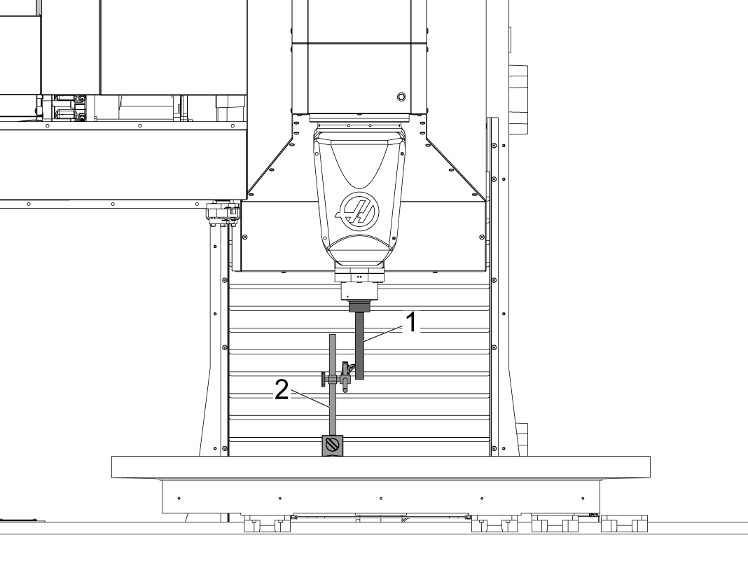
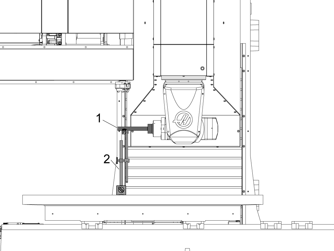
After resetting the tool change offset re-zero the B and C-Axis set up the test bar [1] as shown in the image and place an indicator at the high spot 20 inches away from the test bar [2]. 

NOTE: If the test bar is not larger than 20 inches place it approximately an inch away from the end of the test bar.

2

B-Axis Backlash

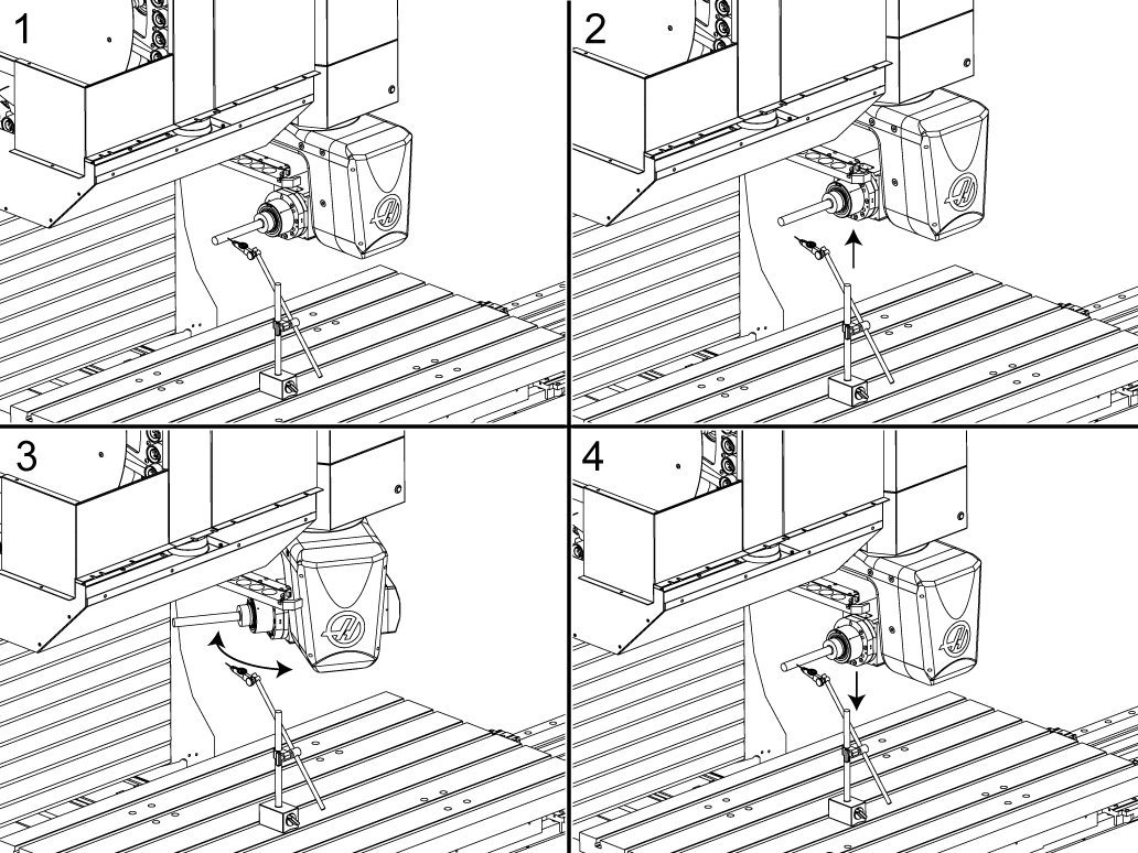
With the indicator set up and B at 0 degrees and C at zero degrees [1] press [POSITION] and navigate to the operators page and set the Y-Axis and B-Axis position to zero.

Move the Y-axis enough to clear the indicator [2]

Rotate the B-Axis -10 degrees and return back to B zero position [3].

Move the Y-Axis back to the zero position on the operators page. 

Record the error value on the indicator.

3

B-Axis Backlash

With the indicator set up in the same starting position verify that the  Y-Axis and B-Axis position are zero on the operators page.

Move the Y-axis enough to clear the indicator [2]

Rotate the B-Axis +10 degrees and return back to B zero position [3].

Move the Y-Axis back to the zero position on the operators page. 

Record the error value on the indicator.

Add both error values from this step and the previous and input double the amount of error into Parameter 6.042 B-AXIS BACKLASH COMPENSATION. (Example total backlash observed : 0.004 inches,  Parameter 6.042 value: 0.008 deg)

This value is NTE 0.0003 in (0.0076 mm).

4

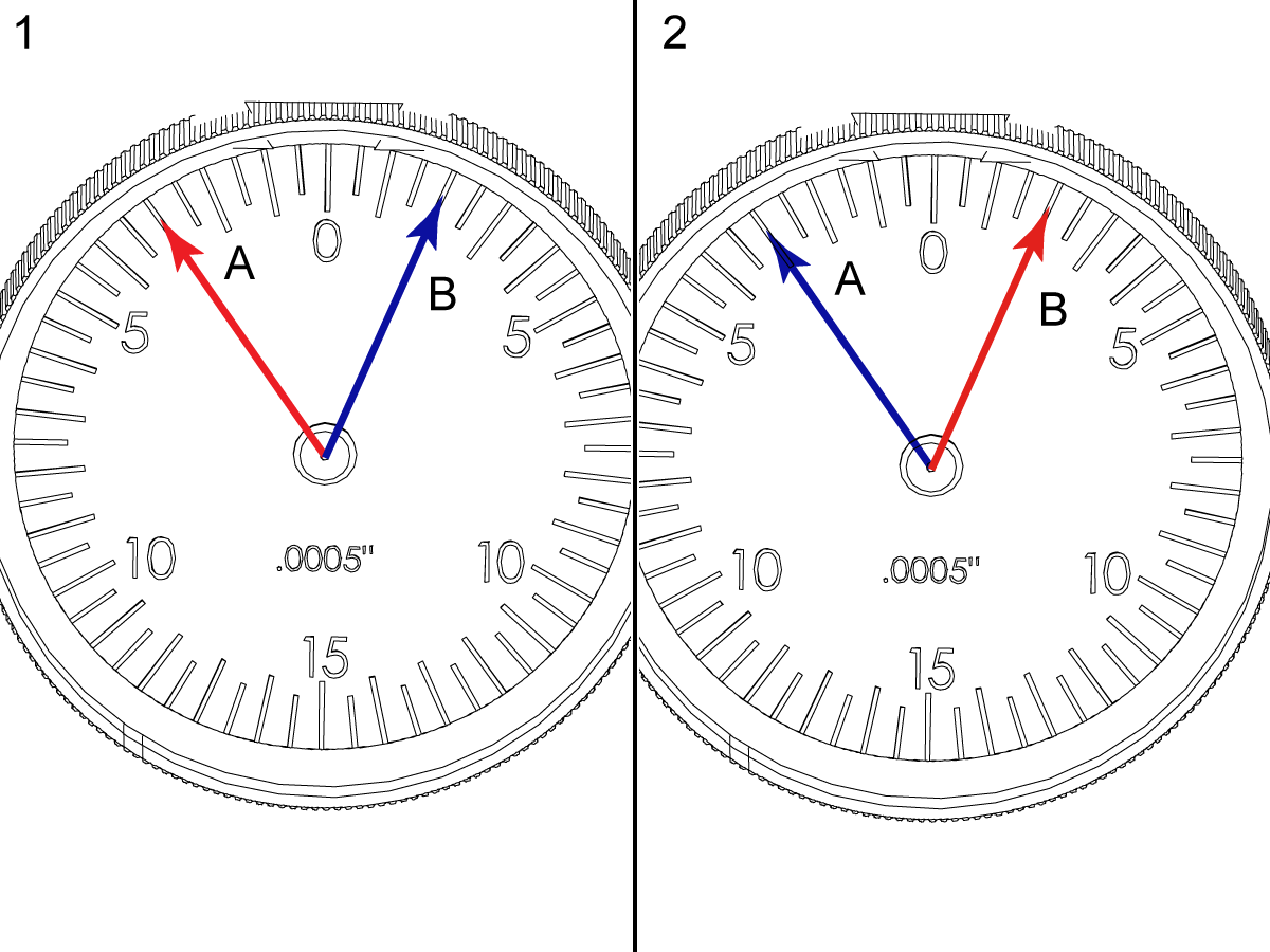
If the backlash value switched direction then the compensation was set too high. 

For example before the compensation value was set the negative motion value read [A] red, and the positive motion the value read [B] blue.

After the compensation value was set the negative motion value read [A] blue, and the positive motion the value read [B] red.

The B & C-Axis backlash  is NTE 0.0003 in (0.0076 mm)

5

C-Axis Backlash

After resetting the tool change offset re-zero the B and C-Axis set up the test bar [1] as shown in the image and place an indicator at the high spot 20 inches away from the test bar [2]. 

NOTE: If the test bar is not larger than 20 inches place it approximately an inch away from the end of the test bar.

6

C-Axis Backlash

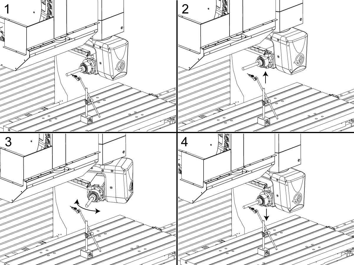
With the indicator set up and B at -90 degrees and C at zero degrees [1] press [POSITION] and navigate to the operators page and set the Z-Axis and C-Axis position to zero.

Raise the Z-axis enough to clear the indicator [2]

Rotate the C-Axis -10 degrees and return back to C zero position [3].

Lower the Z-Axis back to the zero position on the operators page. 

Record the error value on the indicator.

7

C-Axis Backlash

With the indicator set up in the same starting position verify that the  Z-Axis and C-Axis position are zero on the operators page.

Raise the Z-axis enough to clear the indicator [2]

Rotate the C-Axis +10 degrees and return back to C zero position [3].

Lower the Z-Axis back to the zero position on the operators page. 

Record the error value on the indicator.

Add both error values from this step and the previous and input double the amount of error into Parameter 7.042 C-AXIS BACKLASH COMPENSATION. (Example total backlash observed : 0.004 inches,  Parameter 7.042 value: 0.008 deg)

This value is NTE 0.0003 in (0.0076 mm).

8

If the backlash value switched direction then the compensation was set too high. 

For example before the compensation value was set the negative motion value read [A] red, and the positive motion the value read [B] blue.

After the compensation value was set the negative motion value read [A] blue, and the positive motion the value read [B] red.

The B & C-Axis backlash  is NTE 0.0003 in (0.0076 mm)

Complete an Inspection Report

1

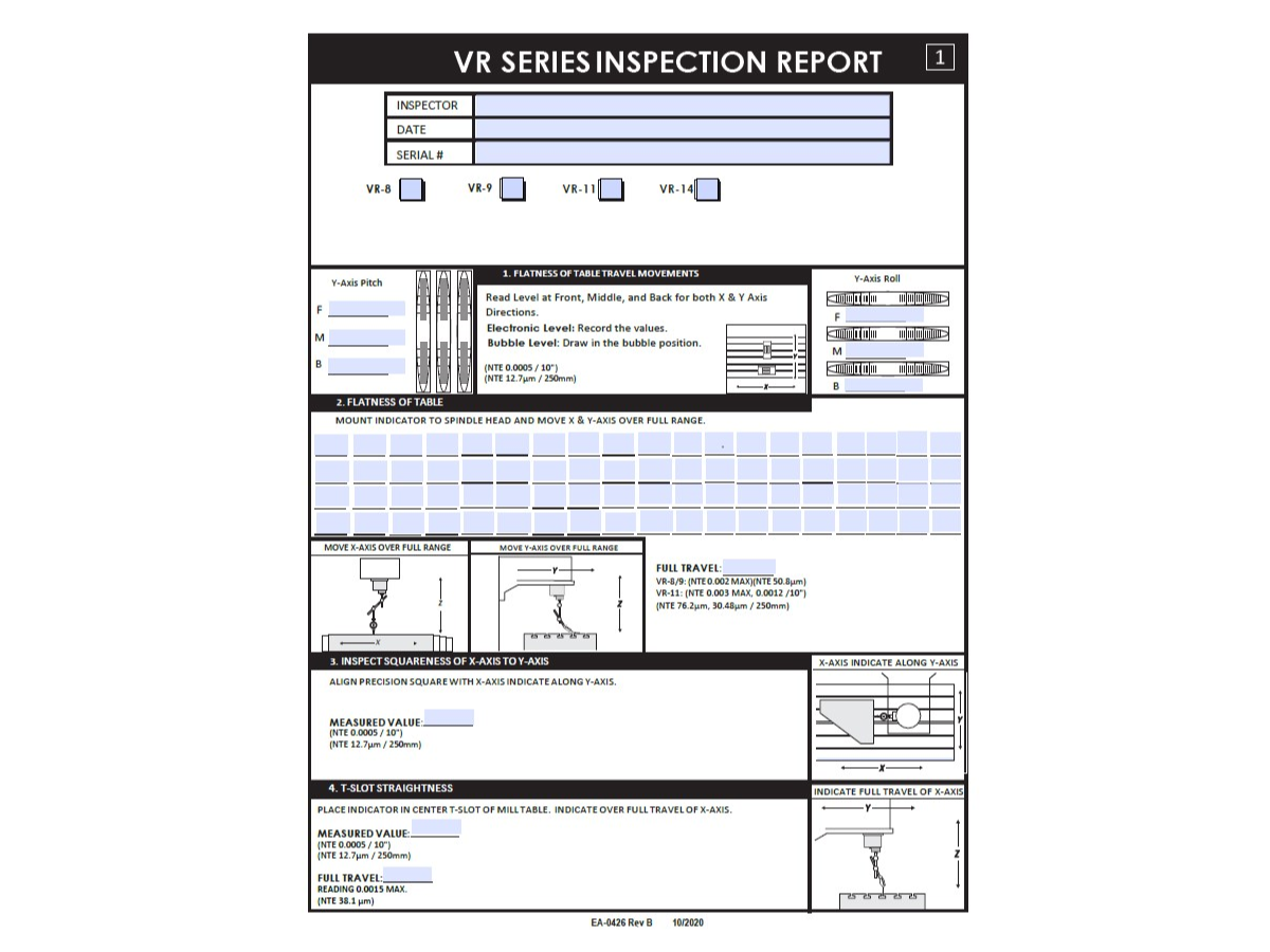
Complete the latest inspection report found in the Alignment Inspection Report and Checklists folder on HBC.

 Note: This site is available only to Haas Service Techs.

Please refer to the H-5AX Single Yoke Spindle Head - Geometry Guide or the GM-2-5AX Head Alignment Procedure for further details on how to perform the 5AX inspection report checks.   

Recently Viewed Items

You Have No Recently Viewed Items Yet

Feedback
Haas Logo

Haas Delivered Price

This price includes shipping cost, export and import duties, insurance, and any other expenses incurred during shipping to a location in France agreed with you as a buyer. No other mandatory costs can be added to the delivery of a Haas CNC Product.

KEEP UP WITH THE LATEST HAAS TIPS AND TECHNOLOGY...

Sign up now!   

HAAS TOOLING ACCEPTS THE FOLLOWING:

  • Service & Support
  • Owners
  • Request Service
  • Operator Manuals
  • Haas Parts
  • Rotary Repair Request
  • Pre-Install Guides
  • Shopping Tools
  • Build & Price a New Haas
  • Available Inventory
  • The Haas Price List
  • CNCA Financing
  • About Haas
  • Accessibility Statement
  • DNSH Statement
  • Export Compliance
  • Careers
  • Certifications & Safety
  • Contact Us
  • History
  • Terms & Conditions
  • Haas Tooling Terms & Conditions
  • Privacy
  • Warranty
  • Haas Community
  • Haas Certification Program
  • Haas Motorsports
  • Gene Haas Foundation
  • Haas Technical Education Community
  • Events
  • Join the Conversation
  • Facebook
  • X
  • Flickr
  • YouTube
  • LinkedIn
  • Instagram
  • TikTok
© 2026 Haas Automation, Inc – CNC Machine Tools
This site is protected by reCAPTCHA and the Google Privacy Policy and Terms of Service apply.

2800 Sturgis Rd., Oxnard, CA 93030
Toll Free: (888) 817-4446 / Fax: 805-278-8554