My Haas Welcome,
!
Haas Tooling MyHaas/HaasConnect Sign In Register Haas Tooling MyHaas/HaasConnect Sign Out Welcome, My Machines Latest Activity My Quotes My Account My Users Sign Out
Find Your Distributor
  1. Select Language
    1. English
    2. Deutsch
    3. Español - ES
    4. Español - MX
    5. Français
    6. Italiano
    7. Português
    8. Český
    9. Dansk
    10. Nederlands
    11. Magyar
    12. Polski
    13. Svenska
    14. Türkçe
    15. 中文
    16. Suomi
    17. Norsk
    18. الإنجليزية
    19. български
    20. Hrvatski
    21. Ελληνικά
    22. Română
    23. Slovenský
    24. Slovenščina
    25. 한국어
    26. 日本語
    27. Українська
  • machines Main Menu
    • Vertical Mills
      Vertical Mills
      Vertical Mills View All
      • Vertical Mills
      • VF Series
      • Universal Machines
      • VR Series
      • VP-5 Prismatic
      • Pallet-Changing VMCs
      • Mini Mills
      • Mold Machines
      • High-Speed Drill Centers
      • Drill/Tap/ Mill Series
      • Toolroom Mills
      • Pocket Mill
      • Compact Mills
      • Gantry Series
      • SR Sheet Routers
      • Extra-Large VMC
      • Double-Column Mills
      • 3+2 Positioning Machines
    • Multi-Axis Solutions
      Multi-Axis Solutions
      Multi-Axis Solutions View All
      • Multi-Axis Solutions
      • Y-Axis Lathes
      • 5-Axis Mills
    • Lathes
      Lathes
      Lathes View All
      • Lathes
      • ST Series
      • Dual-Spindle
      • Box Way Series
      • Toolroom Lathes
      • Chucker Lathe
      • Pocket Lathe
      • Haas Bar Feeders
    • Horizontal Mills
      Horizontal Mills
      Horizontal Mills View All
      • Horizontal Mills
      • 50-Taper
      • 40-Taper
    • Rotaries & Indexers
      Rotaries & Indexers
      Rotaries & Indexers View All
      • Rotaries & Indexers
      • Rotary Tables
      • Indexers
      • 5-Axis Rotaries
      • Extra-Large Rotaries
    • Special Series
      Special Series
      Special Series View All
      • Special Series
      • EU_Series_Redirect
    • Automation Systems
      Automation Systems
      Automation Systems View All
      • Automation Systems
      • Mill Automation
      • Lathe Automation
      • Automatic Parts Loaders
      • Automation Models
    • Desktop Machines
      Desktop Machines
      Desktop Machines View All
      • Desktop Machines
      • Desktop Mill
      • Desktop Lathe
      • Control Simulator, Standard
      • Control Simulator, Premium
    • Shop Equipment
      Shop Equipment
      Shop Equipment View All
      • Shop Equipment
      • Knee Mill
      • Haas Manual Lathes
      • Haas Saws
    • Fabrication Machines
      Fabrication Machines
      Fabrication Machines View All
      • Fabrication Machines
      • Laser Cutting Machines
      • CNC Press Brakes
    • QUICK LINKS Special Series  Special Series 
      EU SERIES EU SERIES BUILD & PRICE | PRICE LIST BUILD & PRICE | PRICE LIST In-Stock Machines In-Stock Machines WHAT’S NEW WHAT’S NEW YOUR FIRST CNC YOUR FIRST CNC
      SHOPPING TOOLS
      • Build & Price a Haas
      • Price List
      • Available Inventory
      • CNCA Financing
      WANT TO TALK TO SOMEONE?

      A Haas Factory Outlet (HFO) can answer your questions, and walk you through your best options.

      CONTACT YOUR DISTRIBUTOR >
  • Options Main Menu
    • The Haas Control Value Option Packages
      Value Option Packages
      Value Option Packages View All
      • Value Option Packages
    • Product Image Spindles
      Spindles
      Spindles View All
      • Spindles
    • Product Image Tool Changers
      Tool Changers
      Tool Changers View All
      • Tool Changers
    • Product Image 4th- | 5th-Axis
      4th- | 5th-Axis
      4th- | 5th-Axis View All
      • 4th- | 5th-Axis
    • Product Image Turrets & Live Tooling
      Turrets & Live Tooling
      Turrets & Live Tooling View All
      • Turrets & Live Tooling
    • Product Image Probing
      Probing
      Probing View All
      • Probing
    • Haas Chip & Coolant Management Chip & Coolant Management
      Chip & Coolant Management
      Chip & Coolant Management View All
      • Chip & Coolant Management
    • The Haas Control The Haas Control
      The Haas Control
      The Haas Control View All
      • The Haas Control
    • Product Image Product Options
      Product Options
      Product Options View All
      • Product Options
    • Product Image Tooling & Fixturing
      Tooling & Fixturing
      Tooling & Fixturing View All
      • Tooling & Fixturing
    • Product Image Workholding
      Workholding
      Workholding View All
      • Workholding
    • Product Image 5-Axis Solutions
      5-Axis Solutions
      5-Axis Solutions View All
      • 5-Axis Solutions
      • 5 Easy Steps to 5-Axis
    • QUICK LINKS Special Series  Special Series 
      EU SERIES EU SERIES BUILD & PRICE | PRICE LIST BUILD & PRICE | PRICE LIST In-Stock Machines In-Stock Machines WHAT’S NEW WHAT’S NEW YOUR FIRST CNC YOUR FIRST CNC
      SHOPPING TOOLS
      • Build & Price a Haas
      • Price List
      • Available Inventory
      • CNCA Financing
      WANT TO TALK TO SOMEONE?

      A Haas Factory Outlet (HFO) can answer your questions, and walk you through your best options.

      CONTACT YOUR DISTRIBUTOR >
  • Why Haas Main Menu
      Discover the Haas Difference
    • Why Haas
    • MyHaas
    • Education Community
    • Industry 4.0
    • Haas Certification
    • Customer Testimonials
  • Service Main Menu
      Welcome to Haas Service
      SERVICE HOME Operator’s Manuals How-To Procedures Troubleshooting Guides Preventive Maintenance Haas Parts Haas Tooling Videos
  • Videos Main Menu
  • Main Menu
    • View All
    • View All
    • View All
    • View All
      • HTEC Curriculum Support
      • Haas Value Option Packages (VOP) Journey
    • View All
      • Haas 10 kg Cobot Package
      • Cobot Kits
      • DC-1 Drill Center
      • CNC Sales News
      • Do More With Your Haas
    • View All
    • View All
      • contact-us-test
      • 4 - AUTOMATION SYSTEMS
      • Carousel-V2
      • expert test
      • Demo_Day_Trident-test
      • Link Test
      • image-sale-tag-test
      • article-list-test
      • Haas 25 kg Robot Package
      • test-algolia-page
    • View All
    • View All
    • View All
    • View All
      • calc-test
    • View All
    • QUICK LINKS Special Series  Special Series 
      EU SERIES EU SERIES BUILD & PRICE | PRICE LIST BUILD & PRICE | PRICE LIST In-Stock Machines In-Stock Machines WHAT’S NEW WHAT’S NEW YOUR FIRST CNC YOUR FIRST CNC
      SHOPPING TOOLS
      • Build & Price a Haas
      • Price List
      • Available Inventory
      • CNCA Financing
      WANT TO TALK TO SOMEONE?

      A Haas Factory Outlet (HFO) can answer your questions, and walk you through your best options.

      CONTACT YOUR DISTRIBUTOR >
  • Haas Tooling Main Menu
  • Haas Service Parts Main Menu

My Haas Welcome,
!
Haas Tooling MyHaas/HaasConnect Sign In Register Haas Tooling MyHaas/HaasConnect Sign Out Welcome, My Machines Latest Activity My Quotes My Account My Users Sign Out
Find Your Distributor
  1. Select Language
    1. English
    2. Deutsch
    3. Español - ES
    4. Español - MX
    5. Français
    6. Italiano
    7. Português
    8. Český
    9. Dansk
    10. Nederlands
    11. Magyar
    12. Polski
    13. Svenska
    14. Türkçe
    15. 中文
    16. Suomi
    17. Norsk
    18. الإنجليزية
    19. български
    20. Hrvatski
    21. Ελληνικά
    22. Română
    23. Slovenský
    24. Slovenščina
    25. 한국어
    26. 日本語
    27. Українська
×

Search Results

Web Pages

Images

    • <
    • 1
    • >

4 - HPB - Installation

Haas Press Brake - Operator's/Service Manual


  • 0 - HPB - Table of Contents
  • 1 - HPB - Introduction
  • 2 - HPB - Legal Information
  • 3 - HPB - Safety
  • 4 - HPB - Installation
  • 5 - HPB - Operation
  • 6 - HPB - Maintenance
  • 7 - HPB - Troubleshooting

Go To :

  • HPB 50-5 Installation
  • HPB 170-10 Installation
Recently Updated

Haas Press Brake 50-5 - Installation


Under Construction

Introduction

Required Tools:

  • 0.02mm Precision Level Gauge 
  • Wrenches
  • Digital Multimeter
  • Complete set of Hex Key Wrenches
  • Screwdrivers

Parts List:

  • Foundation Leveling Plates
  • Tool Box
  • Y1, Y2 Proportional Valves

Required (Not Included):

  • ISO VG 46 hydraulic oil

Pre-Installation and Setup

Environment: 

  • Adequate space around the machine for safe operation and maintenance
  • Clean, dry, and well-ventilate free from dust, corrosion, water leakage, and electrical interference

Foundation Requirements:

  • Concrete foundation thickness: ≥ 200 mm
  • Flatness: ±5 mm over 3 m
  • Must support machine weight (up to 20+ tons depending on model)
  • No soft materials (rubber, wood, etc.) under machine feet

Power Requirements: 

  • 3-phase, 380V, 50/60 Hz
  • Voltage fluctuation: ≤ ±5%
  • Grounding resistance: ≤ 4 ohms
  • Use regulated power supply (recommended) 


Installation

Important: The system has a higher center of gravity, with more weight at the front and less at the rear. During lifting, transportation, and installation, attention must be paid to the position of the center of gravity to prevent the machine from twisting.

Note: Leveling must be done at end of instalation beacuse it requires the machine to be set up so the ram can be opened to place the level on the worktable. Refer to end of installation for leveling instructions. 

Pre-Installation Requirements:

  • Install the machine on a pre-prepared concrete foundation (minimum 200 mm thickness)
  • Place square plates under each leveling bolt
  • Perform a final level check after installation and anchoring


1

Connect the terminal of the overhead rear sheet metal lamp [1].

2

Identify proportional valves Y1 and Y2 before installation.

  • Y1 is located on the left side of the machine.
  • Y2 is located on the right side of the machine.

Install Y2 on the right side, above the machine as shown.

3

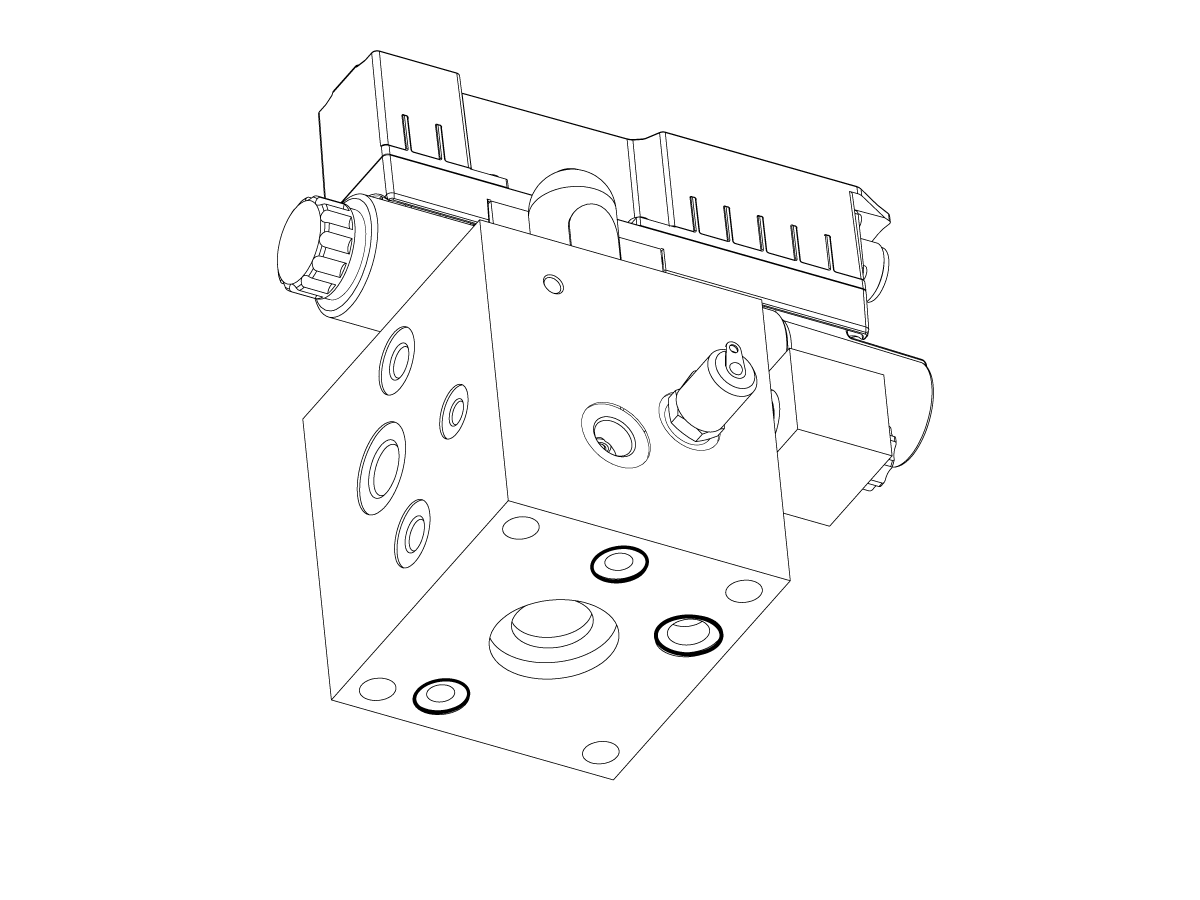
Verify Sealant rings on the bottom of the proportional valve are in place. Otherwise, oil leakage will occur.

4

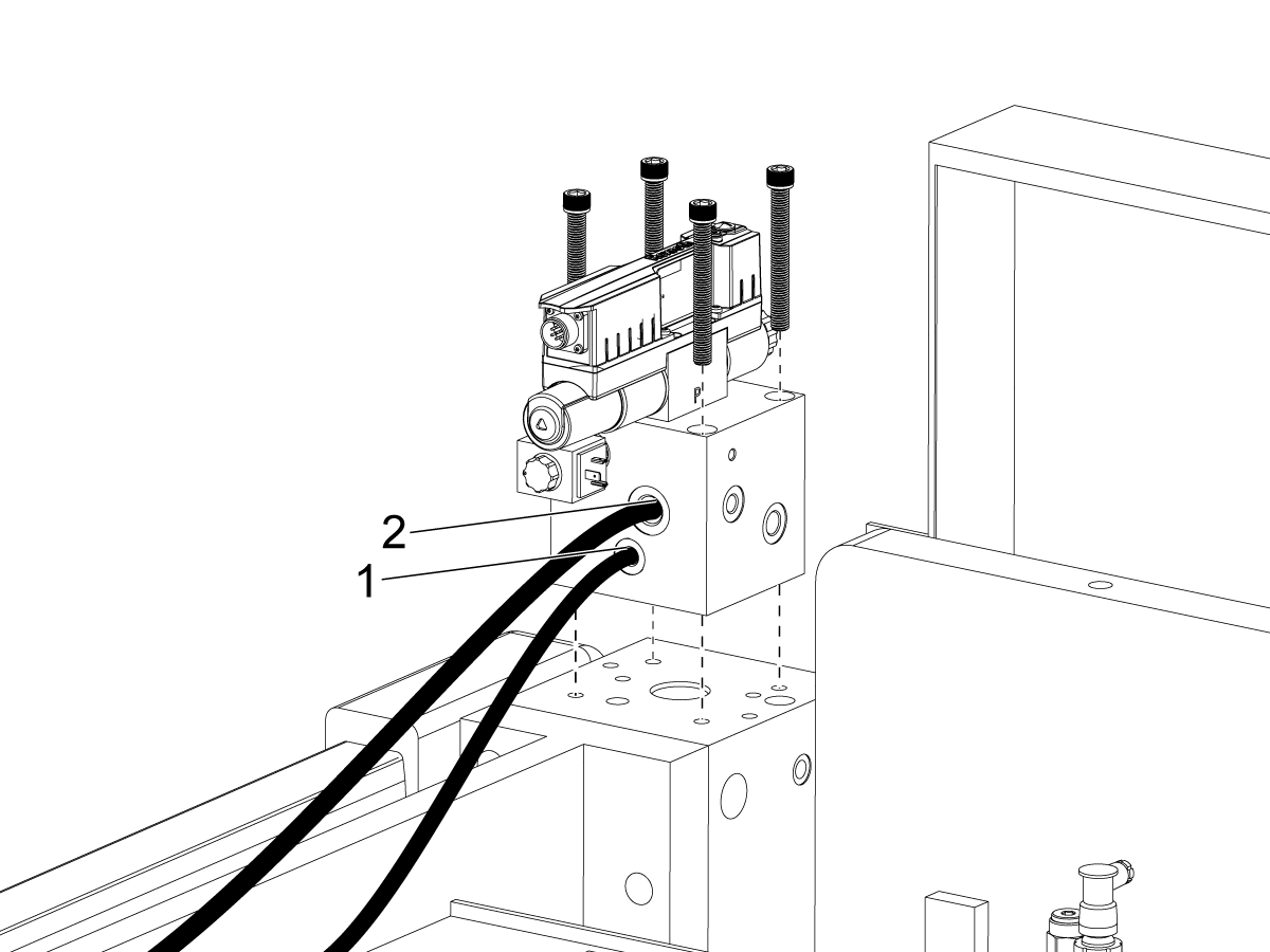
Install proportional value Y2 on the upper right corner of the machine. 

Install the thin hydraulic line [1]

Install the thick hydraulic line [2]

Screw in the proportional valve with the 4 mounting screws.

5

Connect two other connectors/control cable. 

6

Repeat steps 4 and 5 on the Y1 (left) side of the machine. 

7

Install front sheet metal panels using x6 screws as shown. 

Repeat the same process for the other side. 

8

Install the light Curtain. 

The left side is the transmitter and the right side is the reciever. 

9

Install the anti collision bar onto the right side of the bending machine.

10

Fill with oil

The oil level must exceed 80% of the oil gauge range

Holds 120L

Fill with oil

The oil level must exceed 80% of the oil gauge range

  • Maximum capacity: 120 L (31.7 gal)
  • Minimum required for operation: 
  • Recommended operating level: 


Electrical Installation

1

Install foot pedal, plug its connector in the socket at the bottom of the electrical cabinet

2

Terminal block at the bottom inside the cabinet. Machine uses a three-phase 380V power supply.

Machine requires a grounding wire, no neutral wire.

Required power supply voltage for the equipment is 380+/-10%

**Transformer will be needed**

**Voltage regulator**


Power-On Verification

1

Turn on main power supply

Open the Control Cabinet and check whether there is a phase sequence protector.

Condition 1: Phase sequence protector is installed in the electrical cabinet.

Step 1: Turn on the main switch on the electrical cabinet door.

Step 2: Observe the phase sequence protector

  • Green indicator light means the wiring phase sequence is correct
  • Red indicator light indicated an incorrect phase sequence of the power cables. In this case reverse the phase sequence of the wires at the terminal block.

Step 3: After disconnecting the machine from power, open the control cab and swap the phase sequence of any two of the three phase(live) wires on the terminal block. 

Step 4: Power on the machine. Verify Phase Sequence Protector now shows a green indicator light. This confirms correct wiring. 

2

Close control cabinet

Turn on the key switch 

Wait for screen to fully light up

Press oil pump start button.

If green light has turned on, oil pump started successfully. 

3

Press Break Screen Settings....

Software Verification

1

Ensure the oil pump start button is on.

Set the software to manual mode

Press the green start button on the software interface

**At this point the punch will rise and the machine will begin initialization**

**wait for the press brake to complete initialization**

Adjust the Safety Light Curtain

1

Step 1: Lower the Punch to a height of approximately 5-6 cm.

Note: the lunch will lower at a slow speed until the light curtain is adjusted. 

Step 2: Turn off the pump, press the emergency stop button on the control. 

Step 3: Place the auxiliary tooling between the punch and die. 

Step 4: Direct the red light emitted by the left light curtain emitter to the center of the marked hole on the auxiliary tooling

Note: Losen the locking handle of the light curtain to adjust its vertical postion down to the target height. Then tighten the handle to lock it in place. 

2

Loosen the screws attaching the light curtain to the machine to adjust the light curtain left or right to the center position of the auxiliary tooling.

Tighten the fixing screws with a hex key.

3

Remove the auxiliary tooling.

Adjust the right light curtain receiver so that the red light spot aligns with the center of the receiving area.

If the indicator light of the light curtain is on, the signal is well received and the light curtain operates normally.

If the Indicator light is off, the adjustment is not completed, and the position of the light curtain needs further adjustment

After adjustment, the punch can move at high speed.

Leveling

1

Note: When turning the leveling foot bolt clockwise will raise the corresponding foot. Counterclockwise will lower the corresponding foot. 

Place the level horizontally on the lower die., adjust front two feet until level is balanced. 

Place the level vertically on the lower die, adjust the back two feet until level is balanced. 

Place the level at various locations across the lower die to ensure proper leveling. 

Machine Leveling and Installation:

  • Use the machine worktable as the reference surface for leveling
  • Verify machine level in both directions:
    • Maximum deviation: 0.30 mm per 1000 mm
  • Install the machine on a pre-prepared concrete foundation (minimum 200 mm thickness)
  • Secure the machine using anchor bolts
  • Perform a final level check after installation and anchoring
Recently Updated

Haas Press Brake 170-10 - Installation


Under Construction

Introduction

Required Tools:

  • 0.02mm Precision Level Gauge 
  • Wrenches
  • Digital Multimeter
  • Complete set of Hex Key Wrenches
  • Screwdrivers

Parts List:
  • Foundation Leveling Plates
  • Tool Box
  • Y1, Y2 Proportional Valves

Required (Not Included):

  • ISO VG 46 hydraulic oil

Pre-Installation and Setup

Environment: 

  • Adequate space around the machine for safe operation and maintenance
  • Clean, dry, and well-ventilate free from dust, corrosion, water leakage, and electrical interference

Foundation Requirements:

  • Concrete foundation thickness: ≥ 200 mm
  • Flatness: ±5 mm over 3 m
  • Must support machine weight (up to 20+ tons depending on model)
  • No soft materials (rubber, wood, etc.) under machine feet

Power Requirements: 

  • 3-phase, 380V, 50/60 Hz
  • Voltage fluctuation: ≤ ±5%
  • Grounding resistance: ≤ 4 ohms
  • Use regulated power supply (recommended) 


Installation

Important: The system has a higher center of gravity, with more weight at the front and less at the rear. During lifting, transportation, and installation, attention must be paid to the position of the center of gravity to prevent the machine from twisting.

Note: Leveling must be done at end of instalation beacuse it requires the machine to be set up so the ram can be opened to place the level on the worktable. Refer to end of installation for leveling instructions. 

Pre-Installation Requirements:

  • Install the machine on a pre-prepared concrete foundation (minimum 200 mm thickness)
  • Place square plates under each leveling bolt
  • Perform a final level check after installation and anchoring

During installation, ensure that the machine's worktable base does not touch the ground (leave a 3–5mm gap) to prevent the risk of machine tipping.


1

Connect the terminal of the overhead rear sheet metal lamp [1].

2

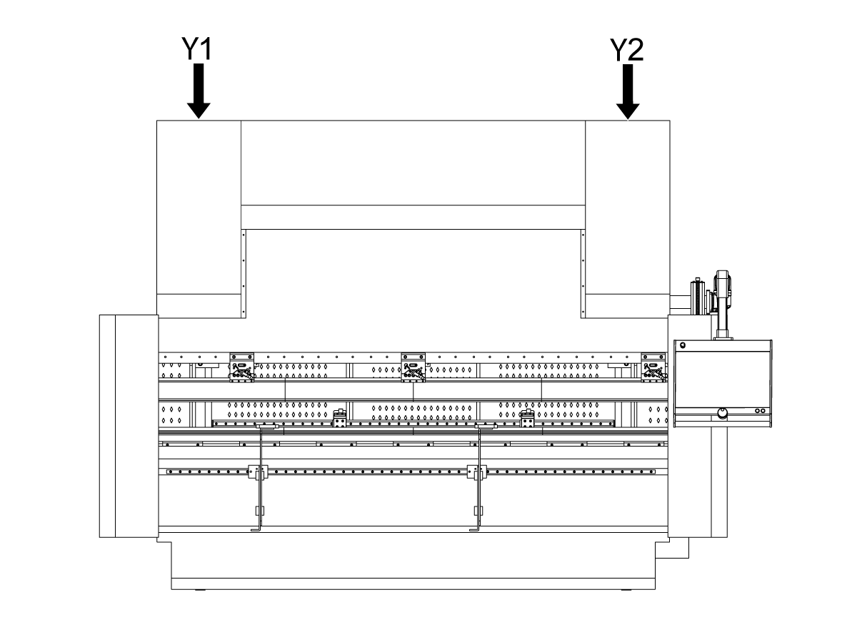
Identify proportional valves Y1 and Y2 before installation.

  • Y1 is located on the left side of the machine.
  • Y2 is located on the right side of the machine.

Install Y2 on the right side, above the machine as shown.

3

Verify sealant rings on the bottom of the proportional valve are in place. Otherwise, oil leakage will occur.

4

Install proportional value Y2 on the upper right corner of the machine. 

Install the thin hydraulic line [1]

Install the thick hydraulic line [2]

Screw in the proportional valve with the 4 mounting screws.

5

Connect the two connectors of the control cable [1] & [2]. 


6

Repeat steps 4 and 5 on the Y1 (left) side of the machine. 

7

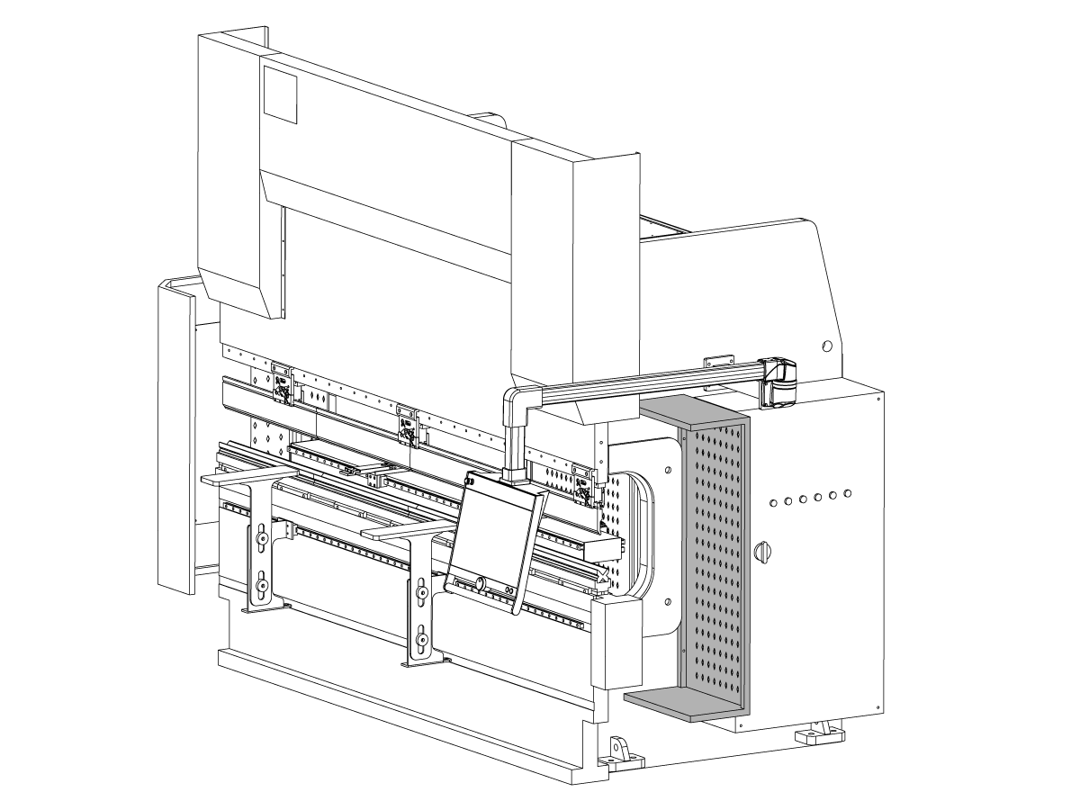
Install front sheet metal panels using x7 screws as shown. 

Repeat the same process for the other side. 

8

Install protective door frame sheet metal. 

9

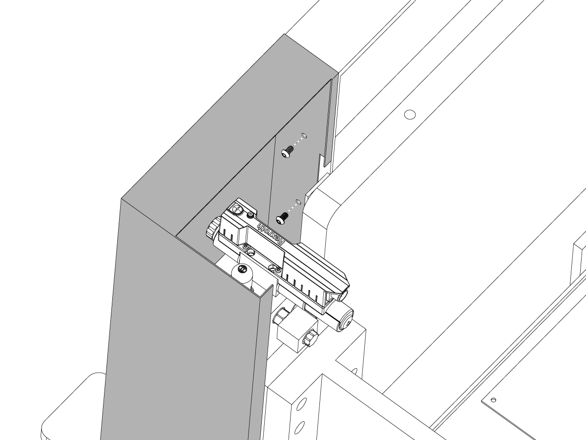
Install the light curtain into side of the ram casting [1]. 

The left side is the transmitter and the right side is the receiver. 

10

Install the sheet metal side doors. 

11

Install the anti collision bar onto the right side of the bending machine.

12

Fill with oil

The oil level must exceed 80% of the oil gauge range

  • Maximum capacity: 270 L (71.3 gal)
  • Minimum required for operation: 216 L (57 gal)
  • Recommended operating level: 230 L (61 gal)


Electrical Safety

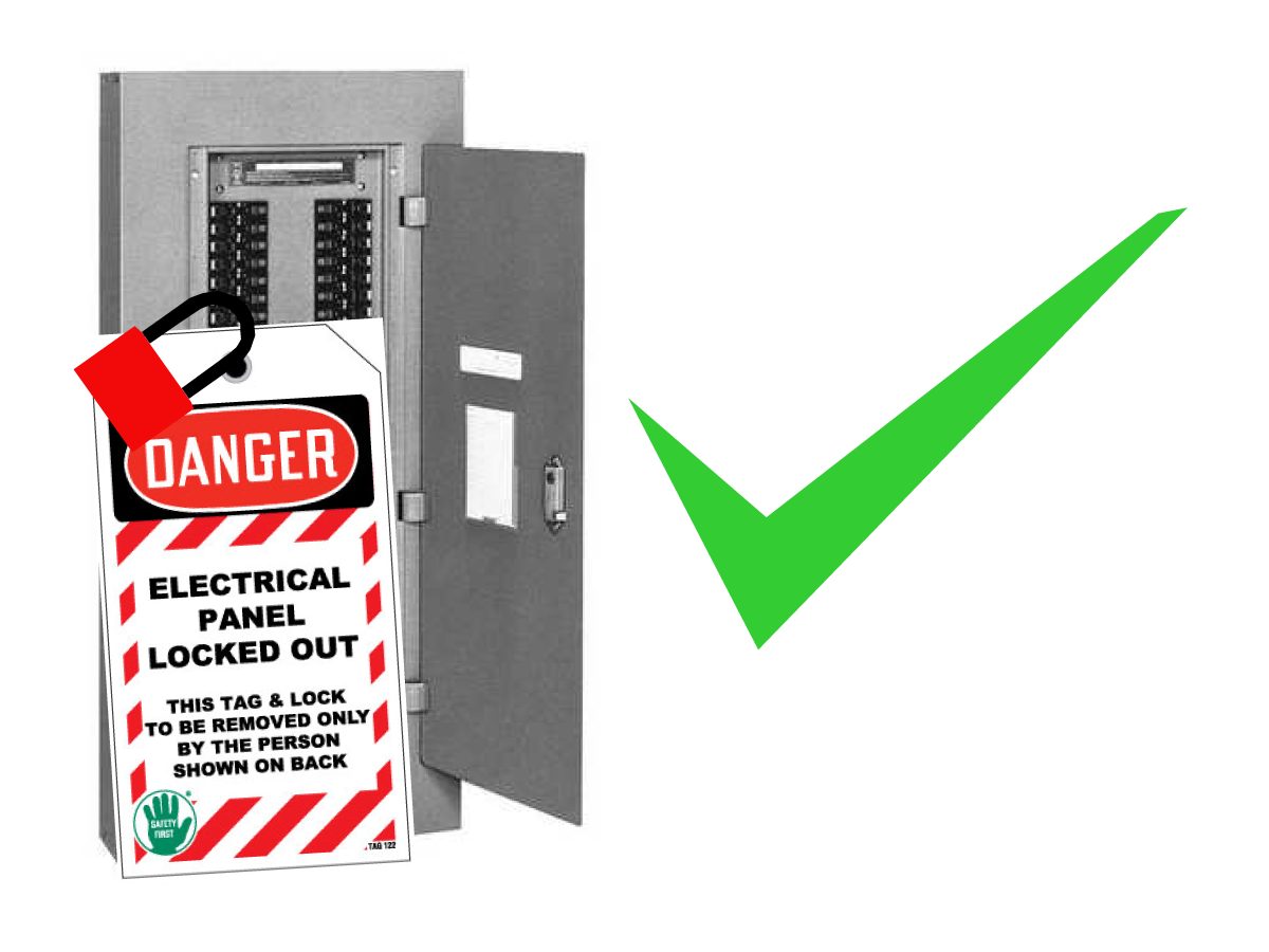
DANGER: Working with the electrical services required for CNC machines is extremely hazardous and can result in serious injury or death.

Before connecting line wires to the CNC:

  • Turn off all power to the machine at the source.
  • Perform a Lockout-Tagout (LOTO) procedure to ensure the power remains off during service.
  • Verify that power has been disconnected by using an AC voltage detector on all incoming lines.

If you are uncertain about how to safely disconnect power or perform LOTO procedures:

  • Do not proceed.
  • Contact qualified personnel or obtain appropriate assistance before continuing.

Failure to follow these precautions may result in electrical shock, equipment damage, or fatal injury.

1

Initial Control Inspection

Danger: At this point, there should be no electrical connection to the machine. Electrical panel must be closed and secured. When main switch is on, there is HIGH VOLTAGE throughout the electrical panel (including the circuit boards and logic circuits) and some components operate at high temperatures. Therefore, exercise extreme caution when working in the panel.

  • Turn the facility disconnect switch or circuit breaker supplying power to the machine OFF.
  • Take sufficient time to check all the components and connectors associated with the circuit boards. Look for any cables that have become disconnected, look for any signs damage and loose parts in the bottom of the panel box. If there are any signs that the machine was mishandled, call the factory before proceeding.

Electrical Installation

1

Install foot pedal, plug its connector in the socket at the bottom of the electrical cabinet

2

Route the facility power supply to the transformer, if required for the site power configuration. Connect the transformer output to the machine terminal block located at the bottom of the electrical cabinet.

The machine requires a three-phase 380 VAC power supply and a protective ground connection. A neutral wire is not required.

Verify that the voltage supplied to the machine is within 380 VAC ±5%. If the facility voltage fluctuates by more than ±5%, install a voltage regulator before powering on the machine.

Note: The machine does not have phase detection. Use a multimeter to verify correct phase rotation before applying power.

Power-On Verification

1

Close control cabinet

Turn on the key switch 

Wait for screen to fully light up

Press oil pump start button.

If green light has turned on, oil pump started successfully. 

2

Press Break Screen Settings....

Software Verification

1

Ensure the oil pump start button is on.

Set the software to manual mode

Press the green start button on the software interface

**At this point the punch will rise and the machine will begin initialization**

**wait for the press brake to complete initialization**

Adjust the Safety Light Curtain

1

Step 1: Lower the Punch to a height of approximately 5-6 cm.

Note: the ram will lower at a slow speed until the light curtain is adjusted. 

Step 2: Turn off the pump, press the emergency stop button on the control. 

Step 3: Place the auxiliary tooling between the punch and die. 

Step 4: Direct the red light emitted by the left light curtain emitter to the center of the marked hole on the auxiliary tooling

Note: Losen the locking handle of the light curtain to adjust its vertical postion down to the target height. Then tighten the handle to lock it in place. 

2

Loosen the screws attaching the light curtain to the machine to adjust the light curtain left or right to the center position of the auxiliary tooling.

Tighten the fixing screws with a hex key.

3

Remove the auxiliary tooling.

Adjust the right light curtain receiver so that the red light spot aligns with the center of the receiving area.

If the indicator light of the light curtain is on, the signal is well received and the light curtain operates normally.

If the Indicator light is off, the adjustment is not completed, and the position of the light curtain needs further adjustment

After adjustment, the punch can move at high speed.

Leveling

1

Note: When turning the leveling foot bolt clockwise will raise the corresponding foot. Counterclockwise will lower the corresponding foot. 

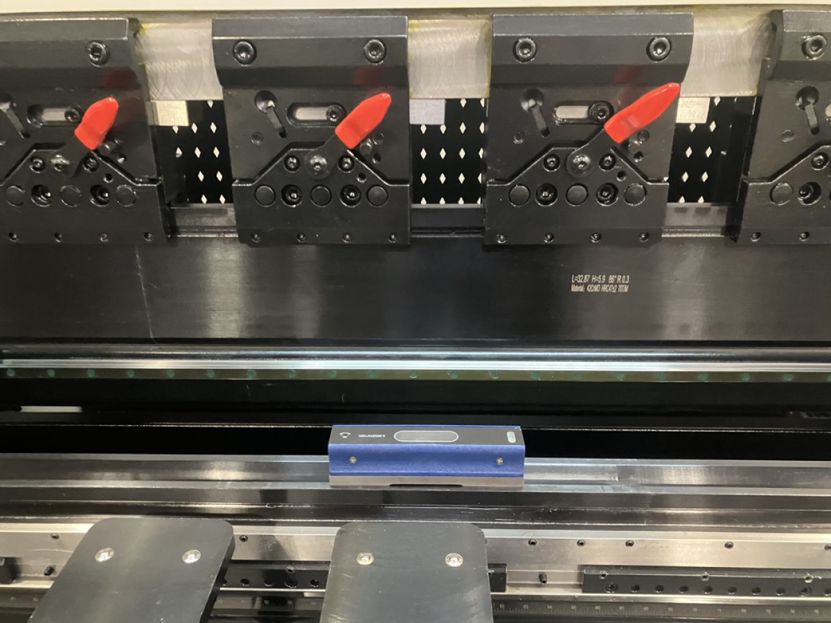
Place the level horizontally on the lower die., adjust front two feet until level is balanced. 

Place the level vertically on the lower die, adjust the back two feet until level is balanced. 

Place the level at various locations across the lower die to ensure proper leveling. 

Recently Viewed Items

You Have No Recently Viewed Items Yet

Feedback
Haas Logo

Haas Delivered Price

This price includes shipping cost, export and import duties, insurance, and any other expenses incurred during shipping to a location in France agreed with you as a buyer. No other mandatory costs can be added to the delivery of a Haas CNC Product.

KEEP UP WITH THE LATEST HAAS TIPS AND TECHNOLOGY...

Sign up now!   

HAAS TOOLING ACCEPTS THE FOLLOWING:

  • Service & Support
  • Owners
  • Request Service
  • Operator Manuals
  • Haas Parts
  • Rotary Repair Request
  • Pre-Install Guides
  • Shopping Tools
  • Build & Price a New Haas
  • Available Inventory
  • The Haas Price List
  • CNCA Financing
  • About Haas
  • Accessibility Statement
  • DNSH Statement
  • Export Compliance
  • Careers
  • Certifications & Safety
  • Contact Us
  • History
  • Terms & Conditions
  • Haas Tooling Terms & Conditions
  • Privacy
  • Warranty
  • Haas Community
  • Haas Certification Program
  • Haas Motorsports
  • Gene Haas Foundation
  • Haas Technical Education Community
  • Events
  • Join the Conversation
  • Facebook
  • X
  • Flickr
  • YouTube
  • LinkedIn
  • Instagram
  • TikTok
© 2026 Haas Automation, Inc – CNC Machine Tools

This site is protected by reCAPTCHA and the Google Privacy Policy and Terms of Service apply.

2800 Sturgis Rd., Oxnard, CA 93030
Toll Free: (888) 817-4446 / Fax: 805-278-8554