My Haas Welcome,
!
Haas Tooling MyHaas/HaasConnect Sign In Register Haas Tooling MyHaas/HaasConnect Sign Out Welcome, My Machines Latest Activity My Quotes My Account My Users Sign Out
Find Your Distributor
  1. Select Language
    1. English
    2. Deutsch
    3. Español - ES
    4. Español - MX
    5. Français
    6. Italiano
    7. Português
    8. Český
    9. Dansk
    10. Nederlands
    11. Magyar
    12. Polski
    13. Svenska
    14. Türkçe
    15. 中文
    16. Suomi
    17. Norsk
    18. الإنجليزية
    19. български
    20. Hrvatski
    21. Ελληνικά
    22. Română
    23. Slovenský
    24. Slovenščina
    25. 한국어
    26. 日本語
    27. Українська
  • machines Main Menu
    • Vertical Mills
      Vertical Mills
      Vertical Mills View All
      • Vertical Mills
      • VF Series
      • Universal Machines
      • VR Series
      • VP-5 Prismatic
      • Pallet-Changing VMCs
      • Mini Mills
      • Mold Machines
      • High-Speed Drill Centers
      • Drill/Tap/ Mill Series
      • Toolroom Mills
      • Pocket Mill
      • Compact Mills
      • Gantry Series
      • SR Sheet Routers
      • Extra-Large VMC
      • Double-Column Mills
      • 3+2 Positioning Machines
    • Multi-Axis Solutions
      Multi-Axis Solutions
      Multi-Axis Solutions View All
      • Multi-Axis Solutions
      • Y-Axis Lathes
      • 5-Axis Mills
    • Lathes
      Lathes
      Lathes View All
      • Lathes
      • ST Series
      • Dual-Spindle
      • Box Way Series
      • Toolroom Lathes
      • Chucker Lathe
      • Pocket Lathe
      • Haas Bar Feeders
    • Horizontal Mills
      Horizontal Mills
      Horizontal Mills View All
      • Horizontal Mills
      • 50-Taper
      • 40-Taper
    • Rotaries & Indexers
      Rotaries & Indexers
      Rotaries & Indexers View All
      • Rotaries & Indexers
      • Rotary Tables
      • Indexers
      • 5-Axis Rotaries
      • Extra-Large Rotaries
    • Special Series
      Special Series
      Special Series View All
      • Special Series
      • EU_Series_Redirect
    • Automation Systems
      Automation Systems
      Automation Systems View All
      • Automation Systems
      • Mill Automation
      • Lathe Automation
      • Automatic Parts Loaders
      • Automation Models
    • Desktop Machines
      Desktop Machines
      Desktop Machines View All
      • Desktop Machines
      • Desktop Mill
      • Desktop Lathe
      • Control Simulator, Standard
      • Control Simulator, Premium
    • Shop Equipment
      Shop Equipment
      Shop Equipment View All
      • Shop Equipment
      • Knee Mill
      • Haas Manual Lathes
      • Haas Saws
    • Fabrication Machines
      Fabrication Machines
      Fabrication Machines View All
      • Fabrication Machines
      • Laser Cutting Machines
      • CNC Press Brakes
    • QUICK LINKS Special Series  Special Series 
      EU SERIES EU SERIES BUILD & PRICE | PRICE LIST BUILD & PRICE | PRICE LIST In-Stock Machines In-Stock Machines WHAT’S NEW WHAT’S NEW YOUR FIRST CNC YOUR FIRST CNC
      SHOPPING TOOLS
      • Build & Price a Haas
      • Price List
      • Available Inventory
      • CNCA Financing
      WANT TO TALK TO SOMEONE?

      A Haas Factory Outlet (HFO) can answer your questions, and walk you through your best options.

      CONTACT YOUR DISTRIBUTOR >
  • Options Main Menu
    • The Haas Control Value Option Packages
      Value Option Packages
      Value Option Packages View All
      • Value Option Packages
    • Product Image Spindles
      Spindles
      Spindles View All
      • Spindles
    • Product Image Tool Changers
      Tool Changers
      Tool Changers View All
      • Tool Changers
    • Product Image 4th- | 5th-Axis
      4th- | 5th-Axis
      4th- | 5th-Axis View All
      • 4th- | 5th-Axis
    • Product Image Turrets & Live Tooling
      Turrets & Live Tooling
      Turrets & Live Tooling View All
      • Turrets & Live Tooling
    • Product Image Probing
      Probing
      Probing View All
      • Probing
    • Haas Chip & Coolant Management Chip & Coolant Management
      Chip & Coolant Management
      Chip & Coolant Management View All
      • Chip & Coolant Management
    • The Haas Control The Haas Control
      The Haas Control
      The Haas Control View All
      • The Haas Control
    • Product Image Product Options
      Product Options
      Product Options View All
      • Product Options
    • Product Image Tooling & Fixturing
      Tooling & Fixturing
      Tooling & Fixturing View All
      • Tooling & Fixturing
    • Product Image Workholding
      Workholding
      Workholding View All
      • Workholding
    • Product Image 5-Axis Solutions
      5-Axis Solutions
      5-Axis Solutions View All
      • 5-Axis Solutions
      • 5 Easy Steps to 5-Axis
    • QUICK LINKS Special Series  Special Series 
      EU SERIES EU SERIES BUILD & PRICE | PRICE LIST BUILD & PRICE | PRICE LIST In-Stock Machines In-Stock Machines WHAT’S NEW WHAT’S NEW YOUR FIRST CNC YOUR FIRST CNC
      SHOPPING TOOLS
      • Build & Price a Haas
      • Price List
      • Available Inventory
      • CNCA Financing
      WANT TO TALK TO SOMEONE?

      A Haas Factory Outlet (HFO) can answer your questions, and walk you through your best options.

      CONTACT YOUR DISTRIBUTOR >
  • Why Haas Main Menu
      Discover the Haas Difference
    • Why Haas
    • MyHaas
    • Education Community
    • Industry 4.0
    • Haas Certification
    • Customer Testimonials
  • Service Main Menu
      Welcome to Haas Service
      SERVICE HOME Operator’s Manuals How-To Procedures Troubleshooting Guides Preventive Maintenance Haas Parts Haas Tooling Videos
  • Videos Main Menu
  • Main Menu
    • View All
    • View All
    • View All
    • View All
      • HTEC Curriculum Support
      • Haas Value Option Packages (VOP) Journey
    • View All
      • Haas 10 kg Cobot Package
      • Cobot Kits
      • DC-1 Drill Center
      • CNC Sales News
      • Do More With Your Haas
    • View All
    • View All
      • contact-us-test
      • 4 - AUTOMATION SYSTEMS
      • Carousel-V2
      • expert test
      • Demo_Day_Trident-test
      • Link Test
      • image-sale-tag-test
      • article-list-test
      • Haas 25 kg Robot Package
      • test-algolia-page
    • View All
    • View All
    • View All
    • View All
      • calc-test
    • View All
    • QUICK LINKS Special Series  Special Series 
      EU SERIES EU SERIES BUILD & PRICE | PRICE LIST BUILD & PRICE | PRICE LIST In-Stock Machines In-Stock Machines WHAT’S NEW WHAT’S NEW YOUR FIRST CNC YOUR FIRST CNC
      SHOPPING TOOLS
      • Build & Price a Haas
      • Price List
      • Available Inventory
      • CNCA Financing
      WANT TO TALK TO SOMEONE?

      A Haas Factory Outlet (HFO) can answer your questions, and walk you through your best options.

      CONTACT YOUR DISTRIBUTOR >
  • Haas Tooling Main Menu
  • Haas Service Parts Main Menu

My Haas Welcome,
!
Haas Tooling MyHaas/HaasConnect Sign In Register Haas Tooling MyHaas/HaasConnect Sign Out Welcome, My Machines Latest Activity My Quotes My Account My Users Sign Out
Find Your Distributor
  1. Select Language
    1. English
    2. Deutsch
    3. Español - ES
    4. Español - MX
    5. Français
    6. Italiano
    7. Português
    8. Český
    9. Dansk
    10. Nederlands
    11. Magyar
    12. Polski
    13. Svenska
    14. Türkçe
    15. 中文
    16. Suomi
    17. Norsk
    18. الإنجليزية
    19. български
    20. Hrvatski
    21. Ελληνικά
    22. Română
    23. Slovenský
    24. Slovenščina
    25. 한국어
    26. 日本語
    27. Українська
×

Search Results

Web Pages

Images

    • <
    • 1
    • >

9- RPL - Pallet Loader Setup

Haas Robot Pallet Loader - Operators / Service Manual


  • 0 - RPL - Table of Contents
  • 1 - RPL - Introduction
  • 2 - RPL - Legal Information
  • 3 - RPL - Safety
  • 4 - RPL - Zero Point Ready - Installation
  • 5 - RPL - Installation
  • 6 - RPL - Fence/Interlock Installation
  • 7 - RPL - Light Curtain Installation
  • 8 - RPL - DCS Setup
  • 9- RPL - Pallet Loader Setup
  • 10 - RPL - Operation
  • 11 - RPL - Maintenance
  • 12 - RPL - Troubleshooting

Go To :

  • 9.1 Setup RPL System
  • 9.2 Set Robot Frames
  • 9.3 Pallet Shelf Layout

9.1 Setup RPL System

Recently Updated

Robot Pallet Loader - Setup System


Revision B - 11/2025

RPL Setup Introduction

This section will walk through setting up the RPL. Including setting all pallets in their correct position.

The RPL system comes with a configuration in the machine that includes a variety of default information for the RPL. Included in this configuration are robot frames, robot motion files, and ready and pickup positions.

These default values in the configuration should work for an RPL system, but it is possible that small adjustments need to be made. See section 9.2 and 9.3 for how to troubleshoot issues with the RPL.

1

Important: Before continuing further check that the default motion files and positions have been loaded correctly.

Press [Current Commands] and then go to the Devices->Robot Motions Setup tab [1].

To determine if the default values were loaded from the configuration, check the following places on the window:

  • The Job field will be empty and the Active Frame will show "Error" [2].
  • All the values for the positions in the table [3] will be empty. 

Note: These are both indicators that the values were not loaded. Refer to the Chapter 12 - Troubleshooting for how to get the default values onto the control.

RPL - Parameter Setup - UMC Machines

1

There are two parameters that need to be set:

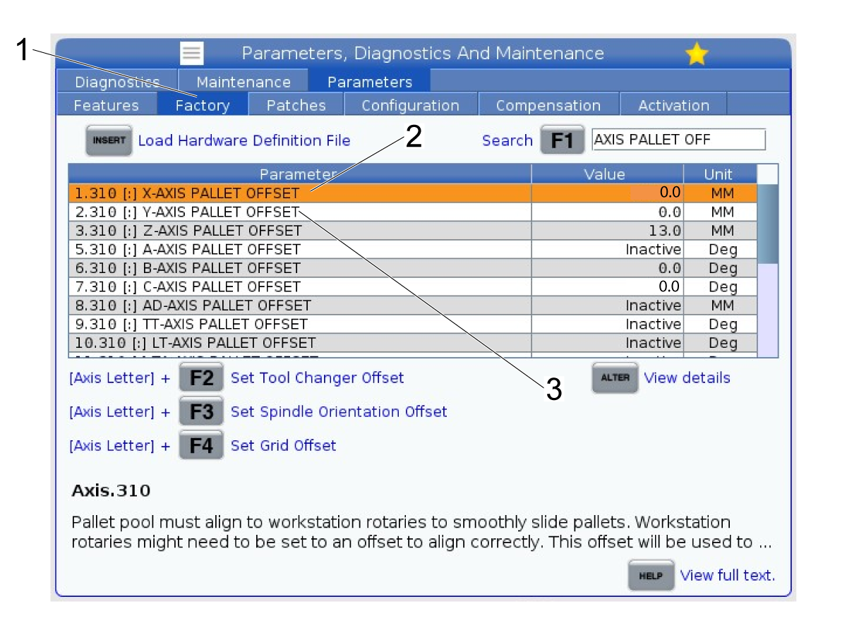
  1. Parameter 1.310 - X-Axis Pallet Offset
  2. Parameter 7.310 - C-axis Pallet Offset (UMC machines only)

Note: You can set Y-axis Pallet Offset and Z-axis Pallet Offset as well if needed for your application.

Parameter 1.310:

Jog the X-axis all the way to the left of the machine near the tool changer. Record the value for the X-axis position.

Navigate to P1.310 in the Factory tab [1]. Find 1.310 and enter the value that was recorded and press [Enter] to set the parameter.

Note: This is the position the X-axis will move to when a pallet change is commanded.

Parameter 7.310:

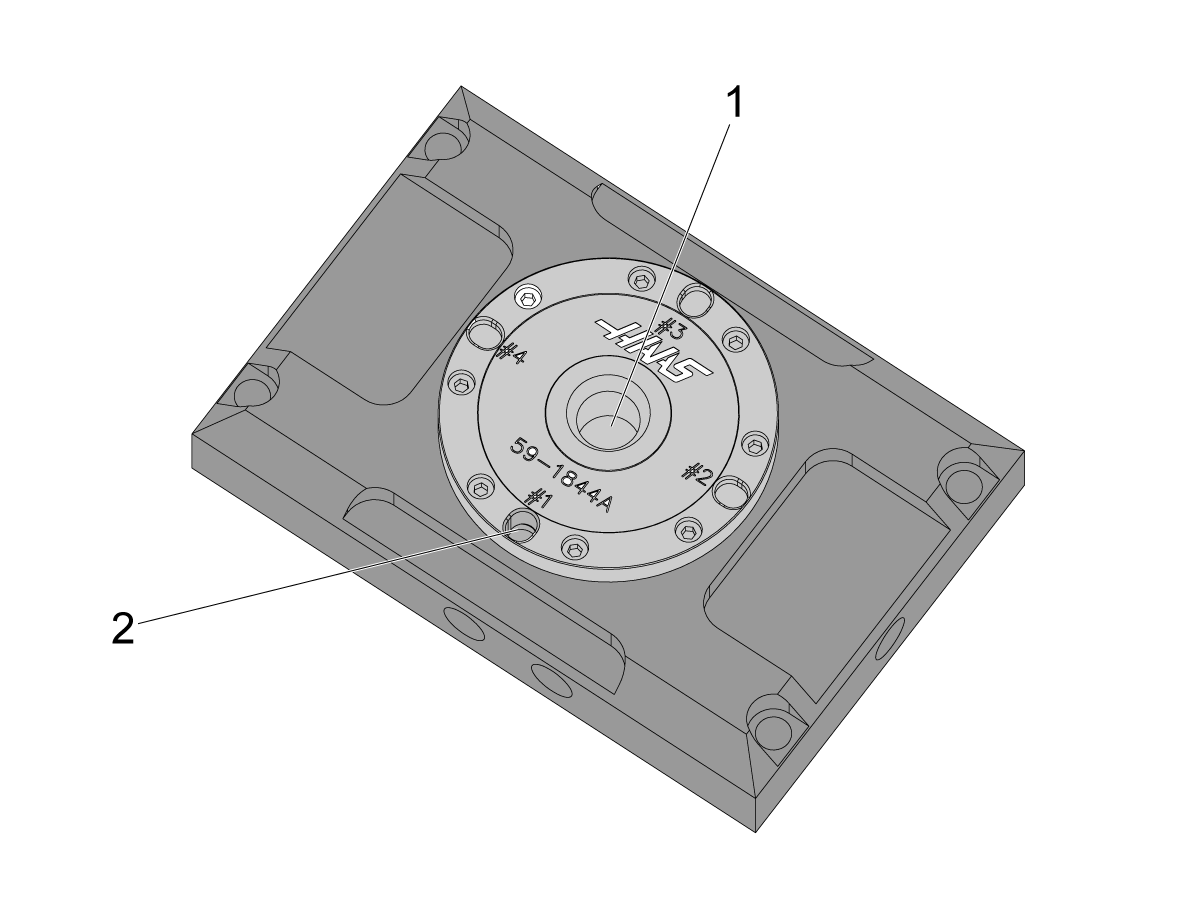
Jog the C-axis so that the back of the zero point receiver is pointed away from the auto window.

Note: The back of the zero point receiver [1] can be found by the deepest slotted bore [2] out of the 4 slots. The deepest bore is where the dowel pin on the pallet will sit when a pallet is clamped in the zero point receiver.

Set the parameter in the same way as P1.310.

Note: This value should be close to 90.0 or -90.0 Deg depending how the pallet receiver was mounted to the table.

RPL - Parameter Setup - VF Machines

1

The table below lists the default values for the pallet offsets on VF machines.

Note: The section below the table gives more information for how to change each of these parameters in case they need to be adjusted from the defaults. Depending on application and machine size, these parameters may need fine tuning.

Factory Setting Description Value
1.310 - X-axis Pallet Offset X-axis moves to this position when a pallet is being changed 759.250
2.310 - Y-axis Pallet Offset Y-axis moves to this position when a pallet is being changed 161.476
3.310 - Z-axis Pallet Offset Z-axis moves to this position when a pallet is being changed 0.0

2

There are two parameters that may need to be set:

  1. Parameter 1.310 - X-Axis Pallet Offset
  2. Parameter 2.310 - Y-Axis Pallet Offset

Parameter 1.310:

Jog the X-axis all the way to the right of the machine near the auto window. Record that position value for the X-axis.

Navigate to P1.310 [2] in the Factory tab [1]. Find 1.310 and enter the value that was recorded and press [Enter] to set the parameter.

Parameter 2.310:

Jog the Y-axis so that the table is centered with the auto window. Record the position for the Y-axis.

Navigate to P1.310 [3] in the Factory tab [1]. Find 2.310 and enter the value that was recorded and press [Enter] to set the parameter.

Set the parameter in the same way as P1.310.

Note: These are the positions that the X and Y axes will move to when a pallet change occurs.

Parameter 3.310:

This is the position that the Z-axis will move to during a pallet change. It should not need to be changed from it's default value of zero.

Set Work Station Pickup location

1

Note: For VF machines, setting the initial pickup position for inside the machine can be done by adjusting the X and Y pallet offsets.  You can adjust the offsets to move the receiver on the table to match where the robot attempts to pickup the pallet. This approach is the same as setting the offsets for a normal Haas pallet pool on a VF.

Even after adjusting the X and Y pallet offsets for a VF machine, the robot's pickup location will likely still need to be adjusted. See the rest of this section for details on setting the point.

2

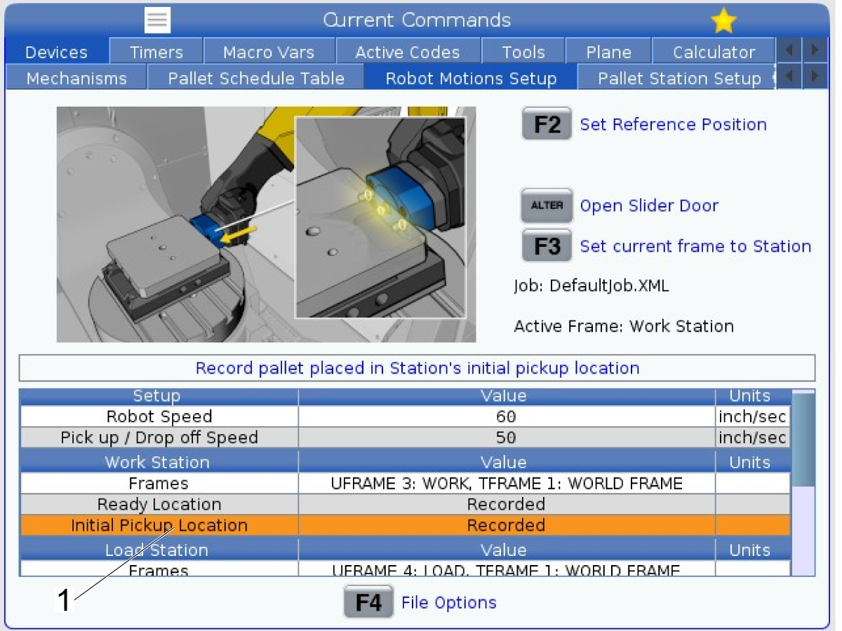
The Work Station initial pickup location [1] will need to be set at installation since the placement of the RPL pallet will vary in relation to the machine.

This is the location to the robot goes to pickup and drop off pallets in the machine's zero point receiver.

This section will show how to record the pickup location.

3

Press [CURRENT COMMANDS] on the Haas control and then navigate to the Robot Motions Setup tab.

Highlight the Initial Pickup Location option [1] under the Work Station [2] section.

Press [Alter] [3] to open the slider window.

Check if the Active Frame is set to "Work Station" [4]. If it is set to a different frame, press [F3] [5] to change the Active Frame to "Work Station."

Make sure the Active Frame is "Work Station" before continuing.

Note: you can also change the active frame by navigating to the Robot tab and then the Frames tab on the Haas control or by entering Recovery.

4

Press [HANDLE JOG] on the control so that you can jog the C-axis to the pallet change offset (P7.310) value. This should be close to either 90.0 degrees or -90.0 degrees [1].

Press [CURRENT COMMANDS] and then go to the Robot tab [2].

Got to the Jogging window [3].

Use the Remote Jog Handle [4] to jog the robot into the machine.

5

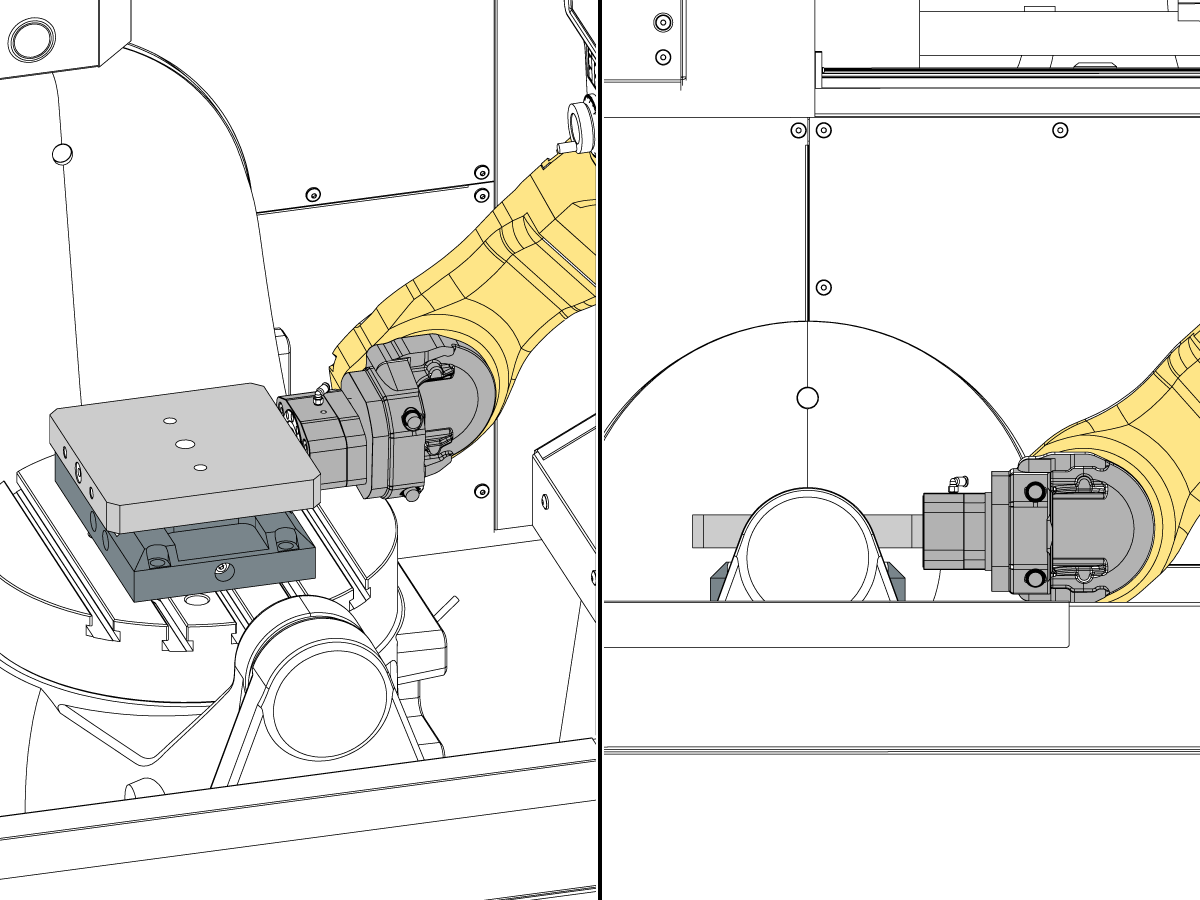
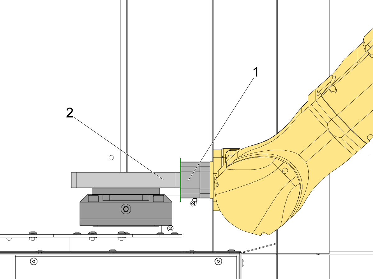
Jog the robot near the platter.

Place a pallet [1] in the zero point receiver [2] with the pull stud [3] facing the robot [4].

Note: The pallet should not be clamped when trying to set the reference position for the grippers. Make sure the pallet is unclamped.

Jog the robot so that the dowel pins on the gripper [5] sit inside the alignment bores in the pallet.

See the next step for more detail on where to jog the robot.

6

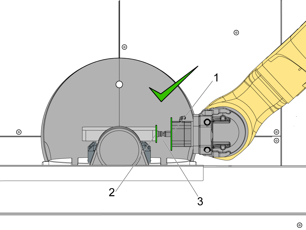
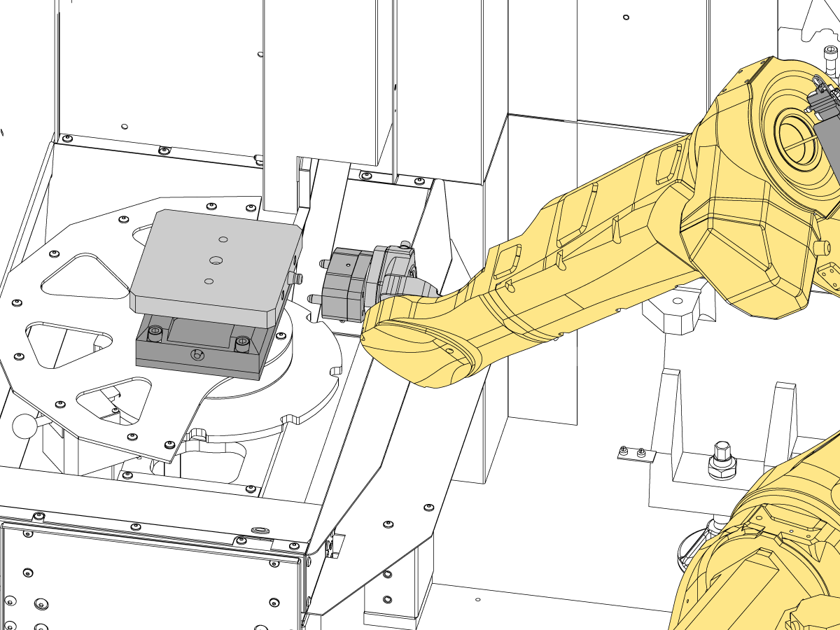
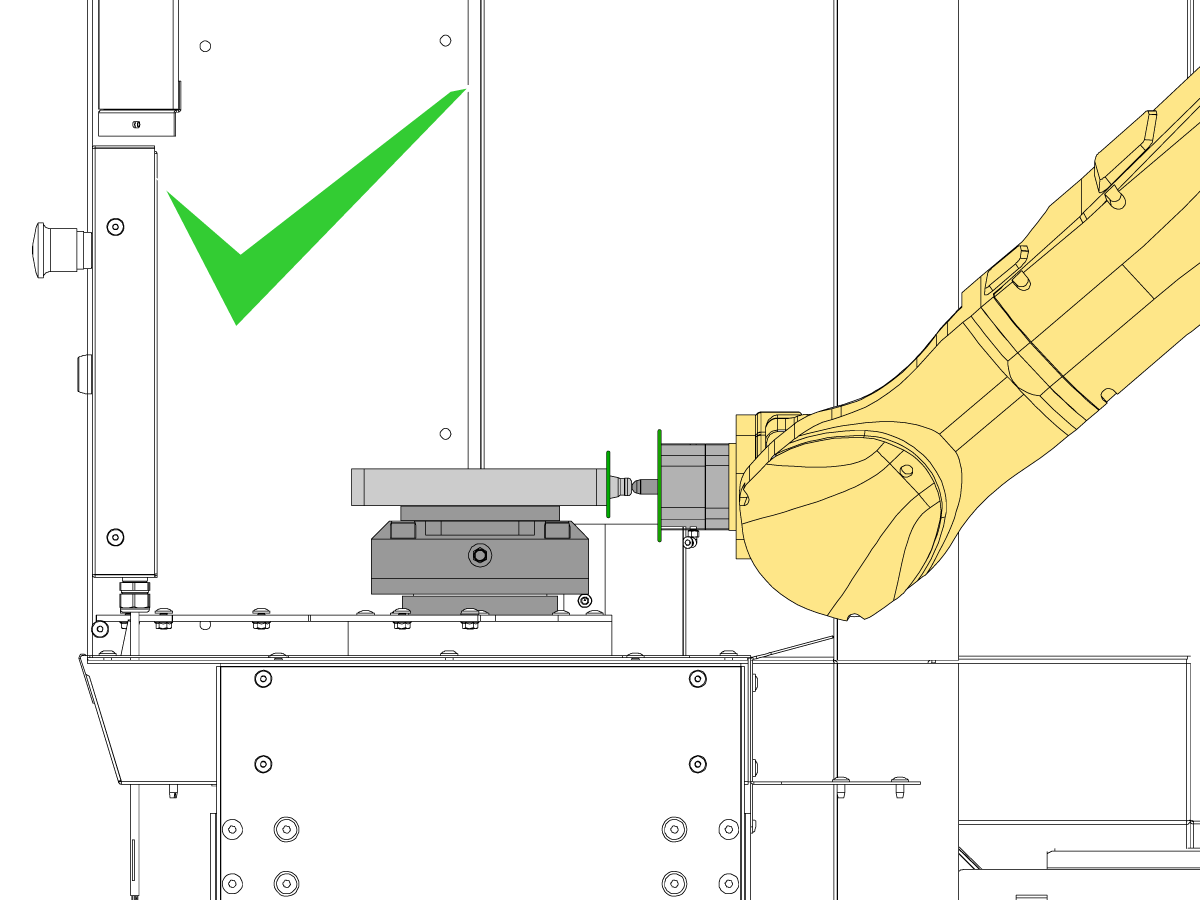
The face of the gripper [1] needs to be as parallel as possible to the face of the pallet [2].

Make sure that the gripper isn't twisted around the x-axis and z-axis as shown in images 3 and 4.

Jog the robot until the gripper is aligned as shown in image 5.

Important: Do not jog the robot in the U, V, or W directions while the dowels are inside the pallet. If the face of gripper and pallet aren't parallel and adjustments need to made, back the gripper out of the pallet and adjust the grippers by jogging with the RJH. Rotating the gripper while inside the pallet could put a load on the robot causing an alarm state.

7

After the gripper face is properly aligned to the pallet, jog the robot using Cartesian coordinates.

Jog the robot so that there is almost contact between the grippers and the pallet. There should be less than 0.002" gap between the gripper and the pallet. 

Note: A shim can be used if needed to verify the gap.

It is OK for there to be contact between the gripper and pallet, but make sure the gripper isn't pushing against the pallet with excess force that will cause misalignment when loading and unloading pallets.

8

To test whether the grippers are in a good spot, test clamping and unclamping the gripper on the pallet.

When clamping, look for if the pallet gets pulled towards the grippers. Or if the grippers get pulled towards the pallet. If there is significant movement when the grippers clamp and unclamp, adjust the position of the grippers.

Note: Slight movements when clamping are acceptable, but it is possible for the pallet to get stuck in the receiver causing the robot to alarm out.

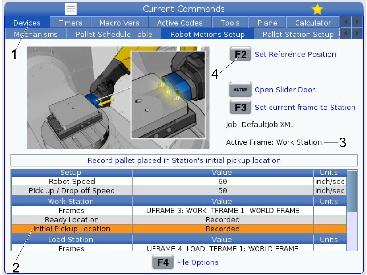
9

With the robot in the same position as the previous step, navigate to the Robot Motions Setup page by pressing [CURRENT COMMANDS] and then going in the "Devices" tab [1].

Highlight the "Initial Pickup Location" [2] inside the Work Station table.

Check that the Active Frame is "Work Station" [3]. 

Press [F2] to set the current robot position as the recorded value for the "Initial Pickup Location."

Note: This is the position the robot will go to when dropping off or picking up pallets from the machine. The other positions on the Robot Motions Setup page should not need to be altered. 

The RPL setup should now be complete. See the operation section for setting up a program to verify the system is working properly.

Setup Load Station Pickup Location

1

The load station initial pickup location [1] may need to be set as well.

This is the position the robot will go to when grabbing a pallet from the load station.

Go to the Robot Motions Setup tab under current commands and highlight the initial pickup location line on the control. This is the position that may need to be adjusted.

2

Use the foot pedal to unclamp the load station zero point receiver.

Place a pallet inside the load station receiver and use the foot pedal to clamp on the pallet. This will be used to help align the grippers to the pallet to set the pickup location.

Turn the machine to 25% rapid.

Go to the Pallet schedule table and press [F4] to pickup the pallet from the load station. As the grippers get close to the pallet watch how the dowel pins are aligned to the pallet.

When the gripper is close to the pallet press the [E-Stop] button to stop the robot. You can then continue jogging the robot to finish aligning the gripper to the pallet.

3

WARNING: Make sure that the gripper and load station are unclamped. If either are clamped then the robot could get servo overload alarms.

On the control switch to the Robot Motions Setup tab.

Press [Handle Jog] and use the RJH to jog the robot.

Note: Since the gripper is already close to it's pickup position use Cartesian motion to jog the robot. Make sure that the active frame is set to Load Station.

Jog the robot close to the pallet. Check to make sure that the gripper is parallel to the pallet before you fully engage the pallet.

Make sure the gripper is not twisted compared to the pallet. Use U, V, and W to rotate the grippers.

Important: Do not jog the robot in the U, V, or W directions while the dowels are inside the pallet. If the face of gripper and pallet aren't parallel and adjustments need to made, back the gripper out of the pallet and adjust the grippers by jogging with the RJH. 

4

Make sure the active frame is the Load Station frame.

Once the gripper is parallel to the pallet, jog the robot in the Z-negative direction so that it moves directly towards the pallet.

Watch the height of the dowel pins to make sure they are aligned to the holes in the pallet. You can make small adjustments in the X and Y directions to fix alignment.

Jog the gripper in until there is almost contact between the gripper [1] and the pallet [2].

Note: To test whether you are in a good location, clamp and unclamp the grippers to see how the arm and pallet move or twist. This can help indicate the direction of misalignment.

5

Once the robot is in the correct position, highlight the position on the Initial Pickup Location [1] row for the Load Station.

Press [F2] [2] on the control to set the current position of the robot as the initial pickup location.

The robot will go to this position when grabbing a pallet from the load station. You can test this by going the Pallet Schedule Table [3] tab and pressing [F3] [4] to have the robot grab a pallet from the load station.

Note: In order to use the Pallet Schedule Table all pallets must be assigned a position. Refer to Section 10.2 Pallet Schedule Table for how to use this tab.

Warning: When running the robot to pickup a pallet for the first time, it's recommended to pick it up at 5% rapid.

Set Initial Pickup Location on Rack

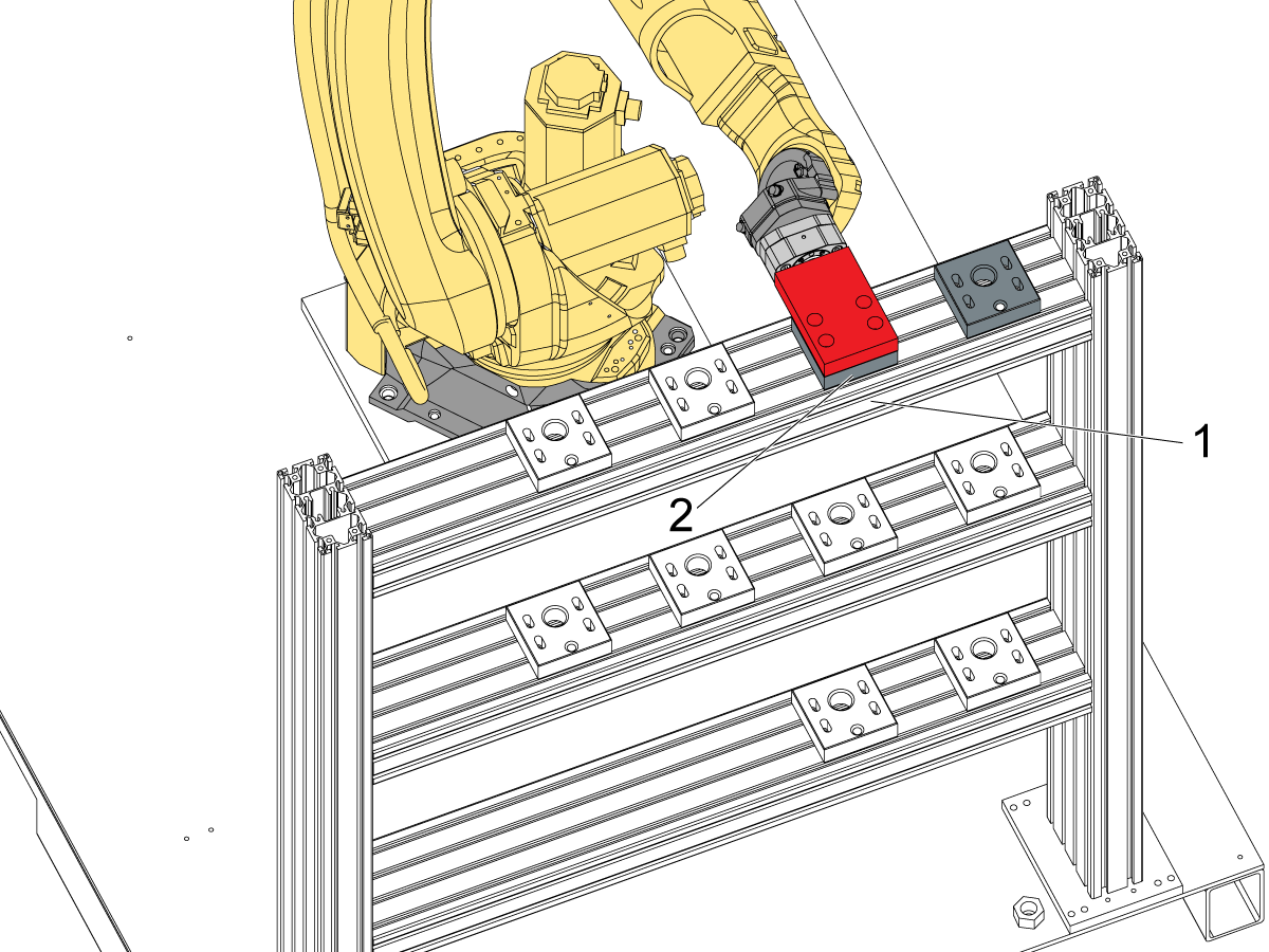
1

The initial pickup location for the racks need to will need to be set.

 Note: The images in this step show setting the initial pickup for rack 2. The same process is done on each of the pallet racks. Rack 2 should only be set for a dual rack RPL.

To set this position, start by clamping the red setup pallet in the gripper.

Use the Pallet Shelf Setup tab inside current commands. On this page press [F1] to switch between Rack 1 and Rack 2.

Highlight Position 2-A1 and press [F3] move to highlighted station. Don't let it go all the way to the position. Be ready to E-Stop the robot when you are close to the rack.

IMPORTANT: Run the robot slowly so that you can E-stop the robot in case it gets close to colliding with the rack.

When the setup pallet is extended above the rack, press E-Stop. You will jog the robot in cartesian motion to align the setup pallet to the 2-A1 pallet holder.

2

After pressing E-Stop, switch to the Robot Motions Setup tab.

Press [Handle Jog] so and select Cartesian mode on the RJH.

Jog the robot so that the red setup pallet lines up with the sides and back  of the pallet holder. Jog down so that the setup pallet is sitting flush or a few mm above the pallet holder.

Refer to the images for what good alignment looks like.

3

Once Aligned, highlight the Initial Pickup Position in the Rack 2 menu [3] and press [F2] to record the position.

Note: Make sure your Active Frame is set to Pallet Station R2 [4]. To change the frame press [F3].

4

Before testing the initial pickup position, check that the frame matches the shelf.

To test the frame, you will first need to recover the robot.

Once recovered, return to the Pallet Shelf Setup tab and clamp the setup pallet in the gripper.

Highlight station 2-A5 [1] and press [F3] [2] to move this pallet location. This will test if the frame matches the shelf, or if a new frame needs to be created.

Warning: Watch the robot carefully as it approaches the 2-A5 location. Its recommended to run the robot slowly to ensure it moves as expected. 

Note: If the robot alarms out moving across the shelf, recover the robot and then return to the ready location before going to the 2-A5 location. 

Note: If the frame is set correctly, the setup pallet will be just above the pallet holder. You should be able to slide the pallet holder underneath the setup pallet, with less than 1/4" gap.

If the setup pallet is way off as shown in the image, then the frame needs to be reset, as well as the initial pickup position.

Note: Refer to the section 9.2 - Set Robot Frames for more information on recreating the rack frames.

5

If the height of setup pallet is correct above the A5 location then the remaining pallet holders can be setup on the second rack.

Move to each of the pallet positions that will be used on the shelf.

Line up the pallet holders [1] underneath where the red setup pallet is located [2].

Once the pallet holder is aligned to the setup pallet, tighten the 4 SHCS [3] to secure the pallet holder in position.

Setup Pallet Holders

1

Before continuing with this section, the pallet shelf grid needs to be configured in the control.

Go to the Pallet Station Setup window in the CURRENT COMMANDS on the control. Before continuing to setup the shelf pallet holders, make sure to verify the template has the following values set:

  • Distance Between Columns: 8.75in (222.25mm)
  • Distance Between Rows: 18.0in (457.2mm)

Warning: Having these fields set to other values can lead to collisions between the robot and the shelf. Always prove out all shelf locations that will be used at low rapids before running a job with the scheduler.

Note: These template values can be adjusted if needed based off the behavior of the robot. 

Note: The RPL comes with 3 pallets as standard. Up to 15 pallets can be used on the RPL system. 

Refer to Section 10.1 Setup Pallet Shelf Grid for more information on how to configure the pallet shelf.

 Note: For Dual Rack RPL's repeat the process for setting up pallet holders on both racks.

2

To set all the pallets in the correct positions on the shelf, navigate to the Pallet Shelf Setup tab on the control.

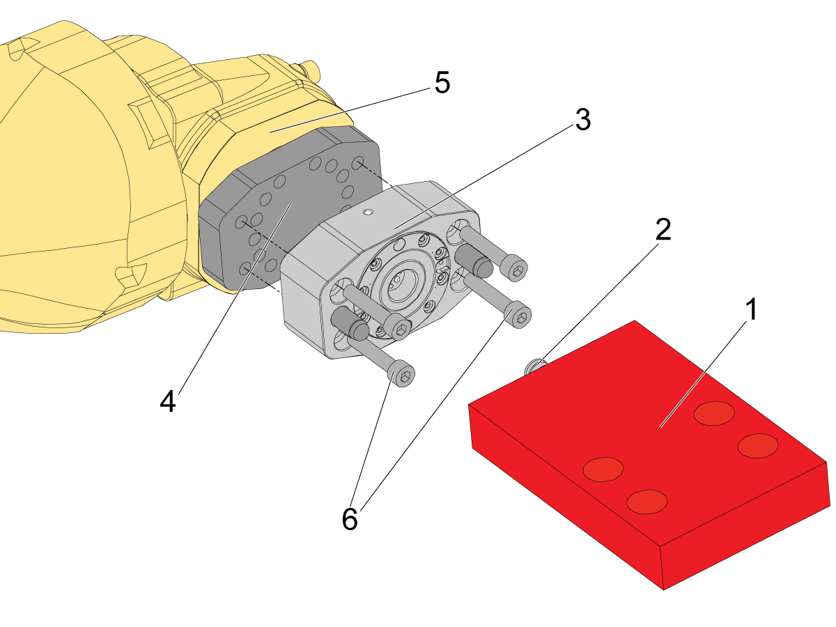
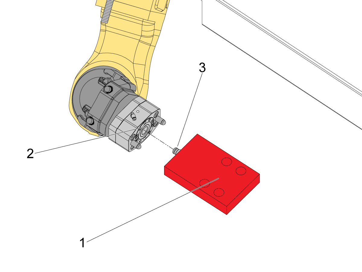
Once on the page you will need to get the RPL-25KG Setup Pallet (30-14426) [1] that includes the pull stud [2] installed to setup each pallet location on the shelf.

Fasten the zero point gripper [3] and mounting plate [4] to the end joint 6 of the HRP-2 [5]. Use the SHCS [6] to mount the gripper to the plate if it isn't already installed.

3

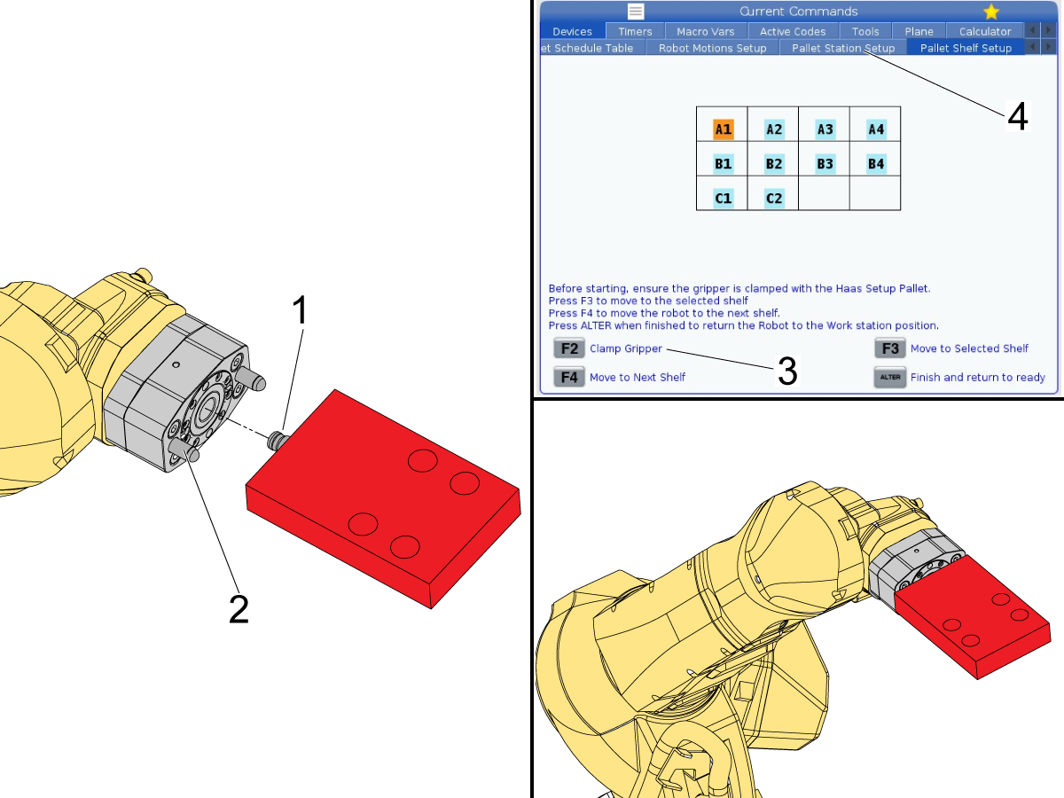
With the pull stud installed on the setup pallet, place the pull stud [1] into the gripper and allow the gripper guide pins [2] to grab the setup pallet.

Once the pallet is fully pressed into the gripper, press [F2] [3] on the control to clamp the gripper.

Note: Make sure the air going to the gripper is on. Otherwise there will be no clamp force on the pull stud.

Note: The arrangement of pallets on the Pallet Shelf Setup page is determined by the information in the Pallet Station Setup tab [4].  Set the desired shelf configuration before continuing further. See Section 10.1 Setup Pallet Shelf Grid for details on that page.

4

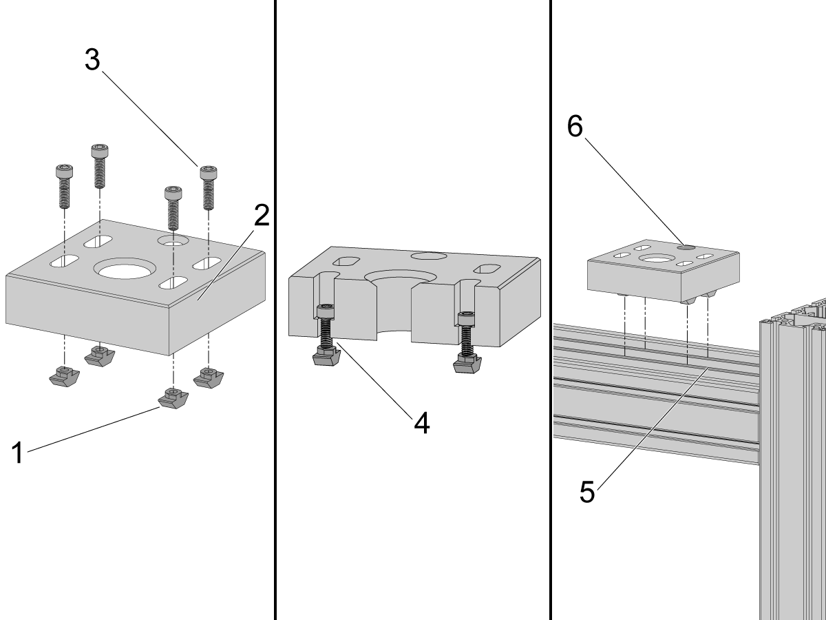
To begin setting up pallet holders on the shelf, fasten the 4 slotted t-nuts [1] to each pallet holder [2] using the 4 M6 x 20mm SHCS [3].

Do not tighten the SHCS at this time. The slotted t-nuts should be barely threaded on the screw so that there is a gap [4] between the pallet holder and the t-nut.

The t-nuts need to be able to move and rotate so that they can get in the t-slot [5] of the shelf. 

After attaching the t-nuts to the pallet holders, place the pallet holder in the shelf so that the t-nuts fall into position.

Note: The alignment hole [6] is the rear of the pallet holder.  Make sure this hole is facing away from the robot

5

Make sure the gripper is clamped on the setup pallet and that the grid of pallets is configured correctly.

Note: If you are using just the 3 pallets that come standard with the RPL, you should only see squares for pallets A1, A2, and A3 on the shelf layout image.  

The example in this procedure shows an application using 10 pallet locations on the shelf. The setup is the same regardless of the number of pallets used.

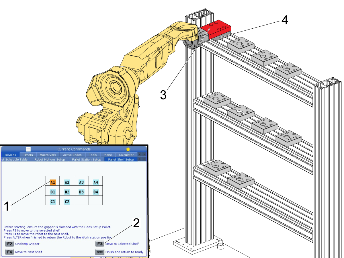
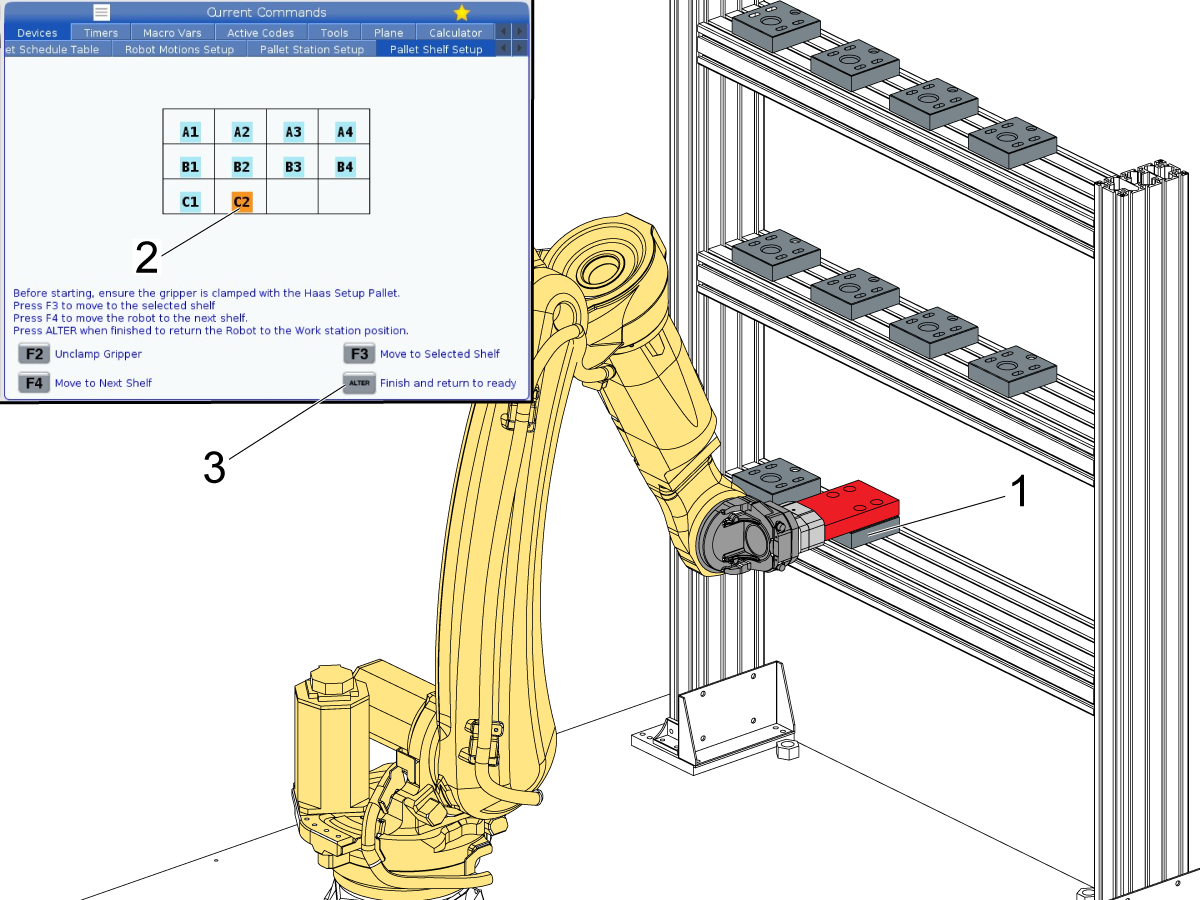
The layout image on this page represents a front view of the shelf. Where spot A1 [1] is the top row left most pallet [2], and spot B4 [3] would be the right most pallet on the middle shelf [4].

6

With the setup pallet [3] clamped in the gripper, make sure that location A1 [1] is highlighted on the control.

Important: Set the control to 5% rapid and watch closely to prevent the robot from damaging anything. 

Pallet holders on the far left side [4] should be roughly 2.25 inches (57mm) from the inside edge of the left post (This is the default initial pickup location). The pallets after that point will be spaced out according to the distance between columns value set on the Pallet Station Setup tab.

Press [F3] on the control [2] to move the robot to the highlighted pallet location.

The robot will move to the shelf and then stop at where pallet 1 should be placed. 

Adjust the first pallet holder [4] under the setup pallet [3] so that the through holes in the setup pallet are directly above the SHCS in the pallet holder [4].

Note: If you want the first pallet to be placed further from the inside edge of the post, you need to change your initial pickup location for the shelf.

7

The pallet holder [1] should slide underneath the setup pallet [2].

The SHCS [3] need to be visible from a top down view as shown in the image. Center the slots on the pallet holder with the access holes in the setup pallet as much as possible. 

Torque down the M6 SHCS [3] fasteners so that the pallet holder is locked in place.

Torque the bolts to their required specs.

Note: This process will be repeated for the remaining pallet holders.

8

On the control, press [F4] [1] to have the robot move to the next location. For example, pressing [F4] on the control will move the robot from pallet A1 to pallet A2 [2] on the shelf.

9

The robot should now be at pallet location A2 [1].

Adjust the pallet holder [2] so that it is in the right place and then tighten the M6 SHCS so that the pallet holder is fixed in position.

Note: This is the same as step 6. Refer to that step for more details.

Press [F4] on the control to move to the next pallet location. Repeat this until all the pallet holders are fixed in location.

10

Once the last pallet holder [1] has been fastened, press [ALTER] on the control [2] to return the robot to the ready location.

Note: In this example with 10 total pallets, pallet location C2 [2] is the last pallet location.

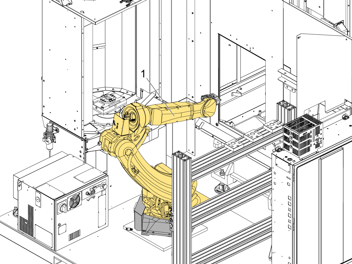
Note: The ready location is the position where the robot is facing the machine in front of the side window. The ready location is shown in the bottom image.

11

With the robot in the ready position [1], press [F2] on the control to unclamp the zero point gripper so that you can remove the setup pallet.

See the next section for setting the pallet drop-off/pick-up locations inside the machine.

9.2 Set Robot Frames

Recently Updated

Robot Pallet Loader - Set Robot Frames


Revision A - 09/2025

Robot User Frames

1

If the robot frames need to be changed, follow this section.

Note: This should only be done in extreme cases.

There are 3 frames needed for the RPL to work:

  1. Shelf
  2. Work Station
  3. Load Station
  4. Shelf 2 (optional)

The shelf frames are the important frames. The shelf frame should be set first if needed and the work station and load station frames can be rotated by 90 degrees each.

The frame for the second shelf needs to be set the same way as the first shelf. Use the following locations on the racks to create the frame using the 3-point method:

  1. Pallet Station C1 (as point 1)
  2. Pallet Station C5 (as point 2)
  3. Pallet Station A5 (as point 3)

This section shows you how to set all of these frames to work with the positioning of the pallet shelf.

Note: The ready and pickup positions will need to be redone once the robot frames are altered.

2

Start by setting setting the frame for the pallet shelf. 

To set this frame use the setup pallet 30-14426 [1]. Clamp the setup pallet to the end of the zero point gripper [2].

Note: The setup pallet 30-14426 includes the pull stud 59-2273 [3].

3

Use the setup pallet to go through the 3-point method for creating a robot frame. 

Refer to section 11.1 - HRP Setup of the HRP manual for more details on the 3-point method for creating frames.

Note: The purpose for creating this frame is to have it match the orientation of the pallet shelf. Because of this the shelf will be used as reference for the 3-point method.

Use the bottom left [1], bottom right [2], and top right [3] corners of the pallet shelf as the reference positions for creating the frame.

4

On the Haas Control press [CURRENT COMMANDS].

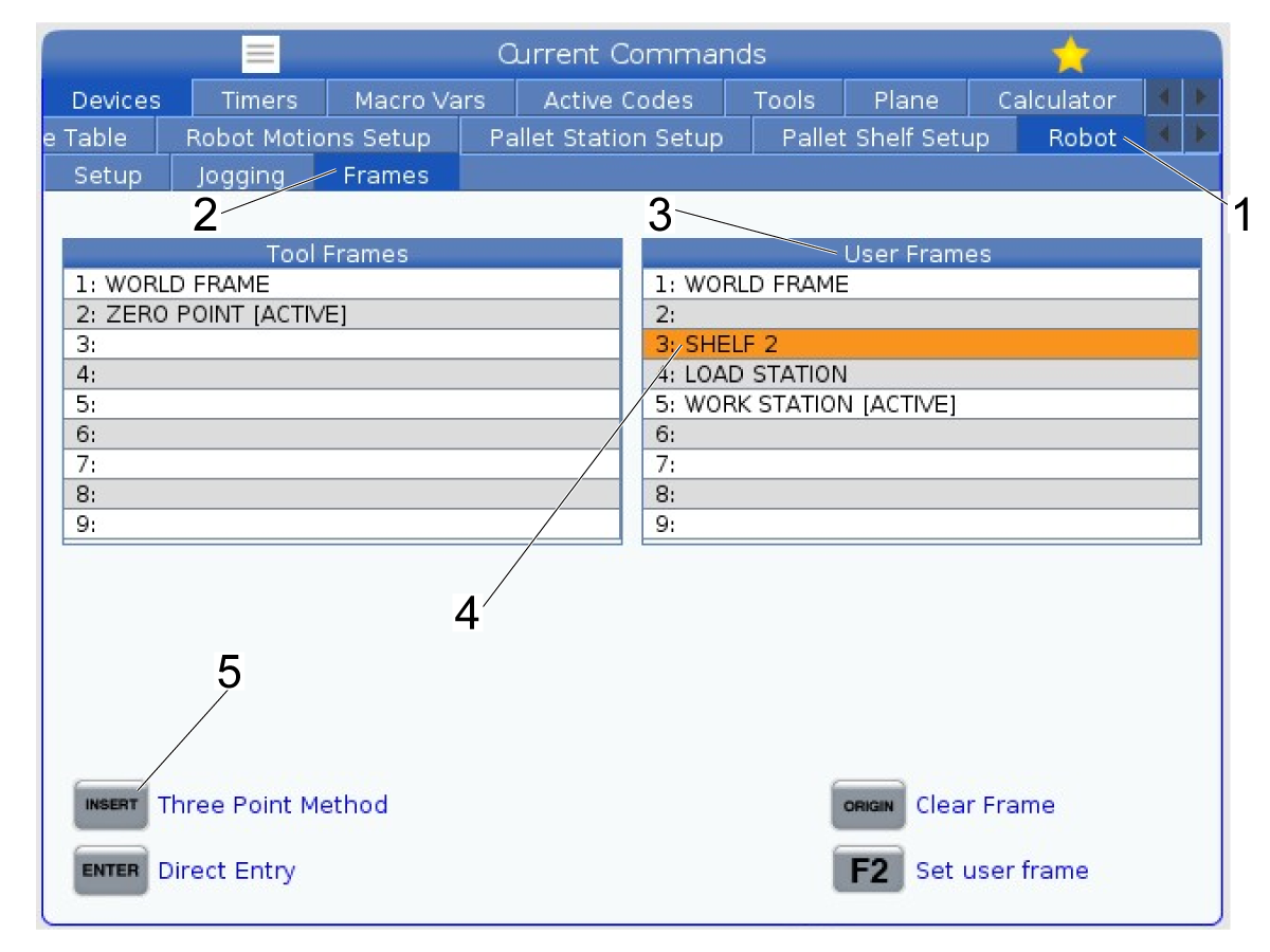
In the Devices tab go to Robot tab [1] and then the Frames window [2].

In the User Frames table [3]  highlight the SHELF frame [4].

To begin the 3-point method press [INSERT] [5] on the control. This will now prompt you to record the positions needed to create the frame.

5

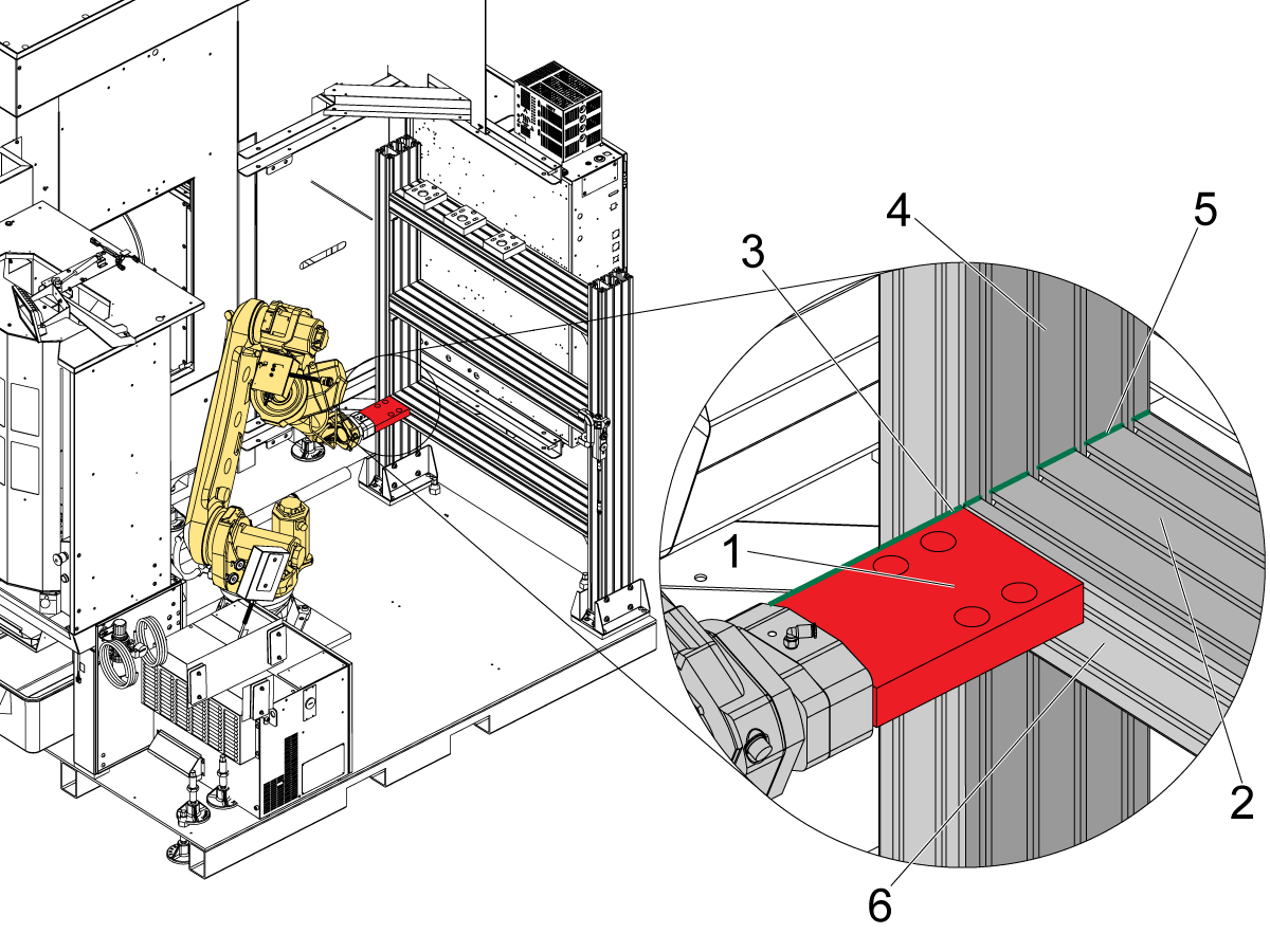
Jog the robot to the bottom left corner of the shelf as shown in the image.

Align the top of the setup pallet [1] with the top surface [2] of the bottom shelf.

Align the left side of the setup pallet [3] with the inside surface [4] of the shelf post.

Note: Make sure that the edge of the setup pallet is aligned with the edge of the shelf [5].

Make sure that setup pallet is flush with the front of the shelf [6]. Both edges of the setup pallet need to be touching the shelf to ensure there is no misalignment between the frame and the shelf.

Press [F2] once the robot is in the correct location to set this as point 1 for the 3-point method.

6

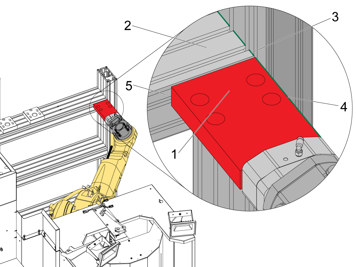
Jog the robot to the bottom right corner of the shelf as shown in the image.

Align the top of the setup pallet [1] with the top surface [2] of the bottom shelf.

Align the right side of the setup pallet [4] with the inside surface [3] of the shelf post.

Note: Make sure that the edge of the setup pallet is aligned with the edge of the shelf. This is shown in the image with the green line.

Make sure that setup pallet is flush with the front of the shelf [5]. Both edges of the setup pallet need to be touching the shelf to ensure there is no misalignment between the frame and the shelf.

Press [F2] once the robot is in the correct location to set this as point 2 for the 3-point method.

7

Jog the robot to the top right corner of the shelf as shown in the image.

Align the top of the setup pallet [1] with the top surface [2] of the bottom shelf.

Align the right side of the setup pallet [4] with the inside surface [3] of the shelf post.

Note: Make sure that the edge of the setup pallet is aligned with the edge of the shelf. This is shown in the image with the green line.

Make sure that setup pallet is flush with the front of the shelf [5]. Both edges of the setup pallet need to be touching the shelf to ensure there is no misalignment between the frame and the shelf.

Press [F2] once the robot is in the correct location to set this as point 2 for the 3-point method.

8

Once the shelf frame is set the work station [1] and load station [2] frames can be set using the direct entry method.

Take a picture of the shelf frame.

For the work station frame, enter the same values for X, Y, Z, W, and P.

Change the value for R by 90 degrees. For example if your shelf frame had an R value of -124.6461, the R value for the work station frame [3] would be -124.6461 + 90 = -34.6461

Repeat this step for the load station frame, by adding 90 to the R value of the work station frame.

9.3 Pallet Shelf Layout

Recently Updated

Robot Pallet Loader - Pallet Shelf Layout


Pallet Shelf Layout

It is possible for the pallet shelf to move during shipping or during a potential crash. If this occurs the pallet shelf may need to be adjusted to work with the existing software.

This section details what to check for if the pallet shelf seems to not be aligned, as well as how to fix the alignment.

Important: Go through section 9.1 Setup RPL System before attempting to make changes to the pallet shelf.  The default software system should match the position and orientation of the shelf. This section should be only used to troubleshoot issues.

1

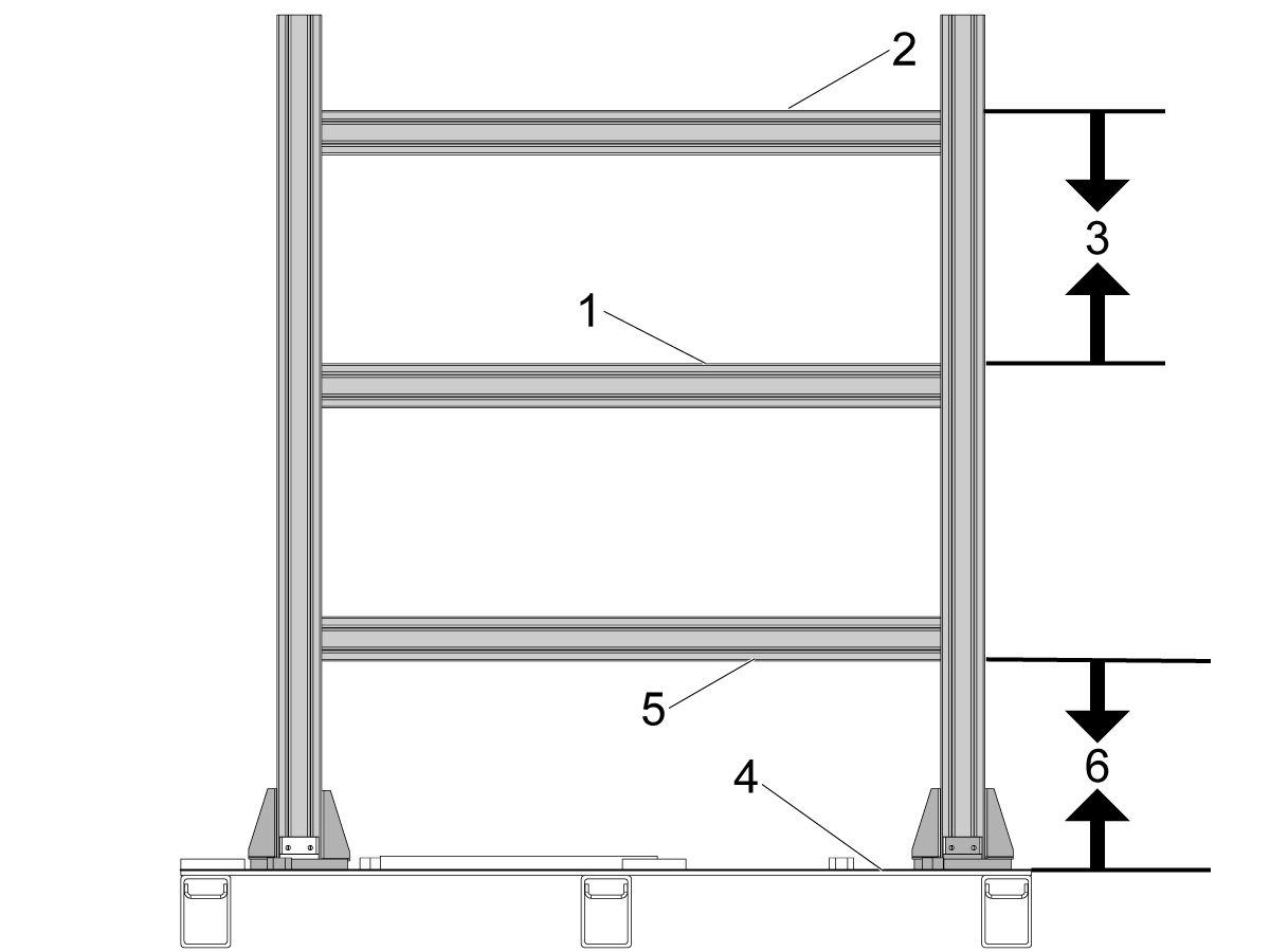
The spacing between shelves needs to be consistent. 

The distance between the top of one shelf [1] and the top of the shelf above [2] should be 18in (457.2mm) [3].

The distance from the base plate [4] to the bottom of the lowest shelf [5] should also be 18in (547.2mm) [6].

2

If the robot position become inaccurate when moving to lower shelves, the posts holding the shelves might not be vertical.

Make sure that the posts holding the shelves [1] are vertical by placing a level along the front [2] of each post and verify that it is level.

Note: The shelf will only be vertical if the metal pallet is level horizontally. Before adjusting the shelf make sure that the metal pallet is level [3] by adjusting the leveling feet.

If the shelf posts are not vertical, loosen the SHCS [4] and then adjust the post until the level shows the post is vertical. Use a mallet to make adjustments on a post. Re-torque the SHCS with the posts level.

3

After adjusting the shelf posts, go through the pallet holder setup in section 9.1.

If the robot moving from station to station is not aligned with the orientation of the shelf, then the robot frame may need to be altered.

Section 9.2 details how to set the robot frames based on the pallet shelf.

Recently Viewed Items

You Have No Recently Viewed Items Yet

Feedback
Haas Logo

Haas Delivered Price

This price includes shipping cost, export and import duties, insurance, and any other expenses incurred during shipping to a location in France agreed with you as a buyer. No other mandatory costs can be added to the delivery of a Haas CNC Product.

KEEP UP WITH THE LATEST HAAS TIPS AND TECHNOLOGY...

Sign up now!   

HAAS TOOLING ACCEPTS THE FOLLOWING:

  • Service & Support
  • Owners
  • Request Service
  • Operator Manuals
  • Haas Parts
  • Rotary Repair Request
  • Pre-Install Guides
  • Shopping Tools
  • Build & Price a New Haas
  • Available Inventory
  • The Haas Price List
  • CNCA Financing
  • About Haas
  • Accessibility Statement
  • DNSH Statement
  • Export Compliance
  • Careers
  • Certifications & Safety
  • Contact Us
  • History
  • Terms & Conditions
  • Haas Tooling Terms & Conditions
  • Privacy
  • Warranty
  • Haas Community
  • Haas Certification Program
  • Haas Motorsports
  • Gene Haas Foundation
  • Haas Technical Education Community
  • Events
  • Join the Conversation
  • Facebook
  • X
  • Flickr
  • YouTube
  • LinkedIn
  • Instagram
  • TikTok
© 2026 Haas Automation, Inc – CNC Machine Tools

This site is protected by reCAPTCHA and the Google Privacy Policy and Terms of Service apply.

2800 Sturgis Rd., Oxnard, CA 93030
Toll Free: (888) 817-4446 / Fax: 805-278-8554