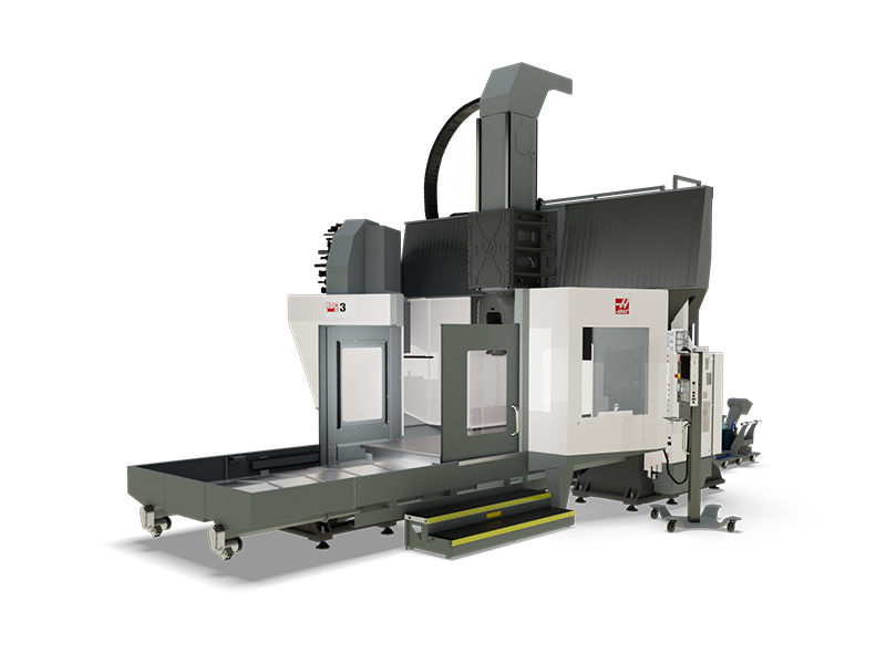
MyHaas Welcome,
!
Haas Tooling Guest Order History MyHaas/HaasConnect Sign In Register Haas Tooling My Account Order History Return History MyHaas/HaasConnect Sign Out Welcome, My Machines Latest Activity My Quotes My Account My Users Sign Out
0
Find Your Distributor
  1. Select Language
    1. English
  • machines Main Menu
    • Haas Vertical Mills Vertical Mills
      Vertical Mills
      Vertical Mills View All
      • Vertical Mills
      • VF Series
      • Universal Machines
      • VR Series
      • VP-5 Prismatic
      • Pallet-Changing VMCs
      • Mini Mills
      • Mold Machines
      • High-Speed Drill Centers
      • Drill/Tap/ Mill Series
      • Toolroom Mills
      • Compact Mills
      • Gantry Series
      • SR Sheet Routers
      • Extra-Large VMC
      • Double-Column Mills
      • Control Simulator
      • Mill Automatic Parts Loader
      • VMC/UMC Side-Loading Automatic Parts Loader
      • Compact Automatic Parts Loader
    • Product Image Multi-Axis Solutions
      Multi-Axis Solutions
      Multi-Axis Solutions View All
      • Multi-Axis Solutions
      • Y-Axis Lathes
      • 5-Axis Mills
    • Haas Lathes Lathes
      Lathes
      Lathes View All
      • Lathes
      • ST Series
      • Dual-Spindle
      • Box Way Series
      • Toolroom Lathes
      • Chucker Lathe
      • Haas Bar Feeder V2
      • Lathe Automatic Parts Loader
    • Haas Horizontal Mills Horizontal Mills
      Horizontal Mills
      Horizontal Mills View All
      • Horizontal Mills
      • 50-Taper
      • 40-Taper
    • Haas Rotaries & Indexers Rotaries & Indexers
      Rotaries & Indexers
      Rotaries & Indexers View All
      • Rotaries & Indexers
      • Rotary Tables
      • Indexers
      • 5-Axis Rotaries
      • Extra-Large Rotaries
    • Special Series
      Special Series
      Special Series View All
      • Special Series
      • EU_Series_Redirect
    • Product Image Automation Systems
      Automation Systems
      Automation Systems View All
      • Automation Systems
      • Mill Automation
      • Lathe Automation
      • Automation Models
    • Haas Drill Centers Desktop Machines
      Desktop Machines
      Desktop Machines View All
      • Desktop Machines
      • Desktop Mill
      • Desktop Lathe
    • Haas Shop Equipment Shop Equipment
      Shop Equipment
      Shop Equipment View All
      • Shop Equipment
      • Bandsaw
      • Knee Mill
      • Surface Grinder, 2550
      • Surface Grinder, 3063
      • Laser Cutting Machine
    • QUICK LINKS Special Series  Special Series 
      EU SERIES EU SERIES BUILD & PRICE | PRICE LIST BUILD & PRICE | PRICE LIST In-Stock Machines In-Stock Machines WHAT’S NEW WHAT’S NEW YOUR FIRST CNC YOUR FIRST CNC
      SHOPPING TOOLS
      • Build & Price a Haas
      • Price List
      • Available Inventory
      • CNCA Financing
      WANT TO TALK TO SOMEONE?

      A Haas Factory Outlet (HFO) can answer your questions, and walk you through your best options.

      CONTACT YOUR DISTRIBUTOR >
  • Options Main Menu
    • The Haas Control Value Option Packages
      Value Option Packages
      Value Option Packages View All
      • Value Option Packages
    • Product Image Spindles
      Spindles
      Spindles View All
      • Spindles
    • Product Image Tool Changers
      Tool Changers
      Tool Changers View All
      • Tool Changers
    • Product Image 4th- | 5th-Axis
      4th- | 5th-Axis
      4th- | 5th-Axis View All
      • 4th- | 5th-Axis
    • Product Image Turrets & Live Tooling
      Turrets & Live Tooling
      Turrets & Live Tooling View All
      • Turrets & Live Tooling
    • Product Image Probing
      Probing
      Probing View All
      • Probing
    • Haas Chip & Coolant Management Chip & Coolant Management
      Chip & Coolant Management
      Chip & Coolant Management View All
      • Chip & Coolant Management
    • The Haas Control The Haas Control
      The Haas Control
      The Haas Control View All
      • The Haas Control
    • Product Image Product Options
      Product Options
      Product Options View All
      • Product Options
    • Product Image Tooling & Fixturing
      Tooling & Fixturing
      Tooling & Fixturing View All
      • Tooling & Fixturing
    • Product Image Workholding
      Workholding
      Workholding View All
      • Workholding
    • Product Image 5-Axis Solutions
      5-Axis Solutions
      5-Axis Solutions View All
      • 5-Axis Solutions
      • 5 Easy Steps to 5-Axis
    • QUICK LINKS Special Series  Special Series 
      EU SERIES EU SERIES BUILD & PRICE | PRICE LIST BUILD & PRICE | PRICE LIST In-Stock Machines In-Stock Machines WHAT’S NEW WHAT’S NEW YOUR FIRST CNC YOUR FIRST CNC
      SHOPPING TOOLS
      • Build & Price a Haas
      • Price List
      • Available Inventory
      • CNCA Financing
      WANT TO TALK TO SOMEONE?

      A Haas Factory Outlet (HFO) can answer your questions, and walk you through your best options.

      CONTACT YOUR DISTRIBUTOR >
  • Why Haas Main Menu
      Discover the Haas Difference
    • Why Haas
    • MyHaas
    • Education Community
    • Industry 4.0
    • Haas Certification
    • Customer Testimonials
  • Service Main Menu
      Welcome to Haas Service
      SERVICE HOME Operator’s Manuals How-To Procedures Troubleshooting Guides Preventive Maintenance Haas Parts Haas Tooling Videos
  • Videos Main Menu
  • Main Menu
    • View All
    • View All
    • View All
    • View All
      • HTEC Curriculum Support
    • View All
      • Haas 10 kg Cobot Package
      • Cobot Kits
    • View All
    • View All
      • 4 - AUTOMATION SYSTEMS
      • Mill Toolholding
      • Carousel-V2
    • View All
    • View All
    • View All
    • View All
    • QUICK LINKS Special Series  Special Series 
      EU SERIES EU SERIES BUILD & PRICE | PRICE LIST BUILD & PRICE | PRICE LIST In-Stock Machines In-Stock Machines WHAT’S NEW WHAT’S NEW YOUR FIRST CNC YOUR FIRST CNC
      SHOPPING TOOLS
      • Build & Price a Haas
      • Price List
      • Available Inventory
      • CNCA Financing
      WANT TO TALK TO SOMEONE?

      A Haas Factory Outlet (HFO) can answer your questions, and walk you through your best options.

      CONTACT YOUR DISTRIBUTOR >
  • Haas Tooling Main Menu
      Automation Accessories Shop Support Mill Toolholding Mill Cutting Tools Boring Systems Mill Workholding Lathe Toolholding Lathe Cutting Tools Lathe Workholding Package Kits ER Collets & Chucks Holemaking Threading Broaching Tombstones & Kits Manual Chucks For Milling Deburring & Abrasives Tool Presetter & Heat Shrinkers Storage & Handling Machine Maintenance Tooling Accessories Apparel & Accessories Measuring & Inspection Winner's Circle Winner's Circle Clearance Today's Hot Deals
    • Haas Tooling
    • Winner's Circle
      Winner's Circle Shop All
      • WINNERS_CIRCLE-1Y
    • Winner's Circle
      Winner's Circle Shop All
      • WC-1Y-EU
    • Today’s Hot Deals
      Today’s Hot Deals Shop All
      • Mill Toolholding
      • Mill Tooling
      • Measuring & Inspection
      • Boring Systems
      • Mill Workholding
      • Shell Mill Kits
      • Lathe Toolholding
      • Lathe Tooling
      • Lathe Workholding
      • ER Collets & Chucks
      • Holemaking
      • Threading
      • Broaching
      • Tool Storage
      • Apparel & Accessories
    • Clearance
      Clearance Shop All
    • Measuring & Inspection
      Measuring & Inspection Shop All
      • Probe Kits & Accessories
      • Edge & Center Finders
      • Comparative Measuring Gauges
      • Height Gauges
      • Calipers
      • Threaded Plug & Ring Gauges
      • Gauge Blocks
      • Pin Gauges
      • Drop Indicators
      • Dial Test Indicators
      • Bore Gauges
      • Indicator Accessories
      • V Blocks
      • Setup Blocks
      • Depth Measuring
      • Micrometers
      • Micrometer Accessories
      • Micrometer Kits
      • Bore Gauge Kits
      • Starter Kits
      • Indicator Kits
      • Caliper Kits
      • Toolholder Check Station
      • Height Setters
      • Coordinate Measuring Machines
    • Automation Accessories
      Automation Accessories Shop All
      • Cobot Kits
      • Cobot Kits
      • Protective Barriers
      • Grippers
      • Robot Cell Accessories
    • Shop Support
      Shop Support Shop All
      • Air Compressors
      • Laser Marking Machines
      • Bandsaw Blades
      • Bandsaw Accessories
      • Surface Grinding Wheels
      • Shop Equipment Accessories
    • Mill Toolholding
      Mill Toolholding Shop All
      • End Mill Holders
      • Shell Mill Holders
      • Shrink Fit Holders
      • ER Collet Chucks
      • Milling Chucks & Collets
      • NC Drilling Chucks
      • Pull Studs / Retention Knobs
      • Rotary Tool Holder & Tool Chuck Kits
      • Hydraulic Milling Chucks & Collets
      • Toolholder Attachments & Wrenches
      • Mill Broaching Holders
    • Mill Tooling
      Mill Tooling Shop All
      • Shell Mill Bodies
      • Milling Inserts
      • End Mills
      • Chamfer Mills & Inserts
      • Indexable End Mill Bodies
      • Ball End Mills
      • Chamfer End Mills
      • Roughing End Mills
      • Indexable Ball End Mills & Inserts
      • Shell Mill Kits
      • Chamfer Mill Kits
      • Indexable End Mill Kits
      • Dovetail Cutters
      • Indexable Dovetail Cutters
      • Engraving End Mills
      • Rotary Burrs / Die Grinding Bits
      • Keyseat Cutters
      • Corner Rounding End Mills
      • Slot Mill Bodies
      • CNC Router Bits For Wood
      • Indexable CNC Router Bits & Inserts
    • Boring Systems
      Boring Systems Shop All
      • Boring Heads & Cartridges
      • Boring Holders & Extensions
    • Mill Workholding
      Mill Workholding Shop All
      • Fixed-Jaw Vises
      • Self-Centering Vises
      • Adapter Plates
      • Vise Jaws
      • Vise Mounts & Fixtures
      • Vise Kits
      • Vise Parallels
      • Rotary Vise Kits
      • Fixture Clamps & Rails
      • Automated Workholding Kits
      • Tooling Fixture Subplates
      • Toolmakers' Vises
      • Clamp Force Gauges
      • Collet Fixtures
      • Angle Plates
    • Lathe Toolholding
      Lathe Toolholding Shop All
      • TL & CL Static Turning Holders
      • BOT Static Turning Holders
      • BMT Static Turning Holders
      • Live / Driven Turning Holders
      • Turning Holder Reduction Sleeves / Bushings
      • VDI Static Turning Holders
      • Turning Holder Accessories
    • Lathe Tooling
      Lathe Tooling Shop All
      • Cut-Off Tool Blocks & Blades
      • Cut-Off Tooling Kits
      • Turning Inserts
      • Grooving & Cut-Off Tools
      • Internal (ID) Grooving & Threading Tools
      • Threading Inserts
      • Threading Tools
      • Boring Bars / Internal (ID) Turning Tools
      • External (OD) Turning Tools
      • Cermet Turning Inserts
      • CBN Turning Inserts
      • Haas Notch Grooving & Threading Inserts
      • Haas Notch Grooving & Threading Tools
      • Micro Turning Tools
      • Desktop Lathe Tools
    • Lathe Workholding
      Lathe Workholding Shop All
      • Live Centers
      • Spindle Reduction Sleeves / Liners
      • Quick-Change Collets
      • Quick-Change Collet Chucks
      • 5C Collets
      • 5C Collet Sets
      • Lathe Jaw Boring Rings
      • Lathe Jaws
      • Bar Pullers
      • Scroll Chucks
      • Guide Pins
      • Collet Accessories
    • Package Kits
      Package Kits Shop All
      • Chip Clearing Fan Kits
      • Cutting Tool Kits
      • Indexable End Mill Kits
      • Cut-Off Tool Block & Blade Kits
      • Drill & Tap Kits
      • Indexable Drilling Kits
      • Shell Mill Kits
      • Chamfer Mill Kits
      • Rotary Tool Holder & Tool Chuck Kits
      • Lathe Starter Kits
      • Workholding Kits
      • Rotary Vise Kits
      • Vise Kits
      • 3-Jaw Chuck Kits for Mills
      • Tombstone Kits
      • Reduction Sleeve Kits
      • Automated Workholding Kits
      • Measuring & Inspection Kits
      • Starter Kits
      • Bore Gauge Kits
      • Caliper Kits
      • Indicator Kits
      • Micrometer Kits
    • ER Collets & Chucks
      ER Collets & Chucks Shop All
      • ER Straight-Bore Collets
      • ER Sealed Collets
      • ER Tap Collets
      • ER Collet Sets & Accessories
      • ER Collet Chucks
      • Straight Shank ER Collet Chucks
      • Straight Shank Keyless NC Drilling Chucks
    • Holemaking
      Holemaking Shop All
      • Carbide Drills
      • Indexable Drill Bodies
      • Indexable Drill Inserts
      • Modular Drill Bodies
      • Modular Drill Heads
      • Cobalt Drills & Sets
      • Center Drills
      • Reamers
      • Indexable Drilling Kits
      • Spot Drills
      • Spade Drill Bodies
      • Spade Drill Inserts
      • Countersinks
    • Threading
      Threading Shop All
      • Taps
      • Threading Inserts
      • Threading Tools
      • Thread Mills
      • Pipe Taps
      • Drill Tap Kits
    • Broaching
      Broaching Shop All
      • Broaching Tools
      • Broaching Inserts
    • Tombstones
      Tombstones Shop All
      • Tombstones
      • Tombstone Kits
      • Vise Cluster Towers
    • Manual Chucks For Milling
      Manual Chucks For Milling Shop All
      • 5C Indexer Chucks
      • 3-Jaw Chucks & Mounts for Mills
    • Deburring & Abrasives
      Deburring & Abrasives Shop All
      • Abrasive Pads
      • Deburr Tools
      • Deburr Wheels
      • Abrasive Sheets & Rolls
      • Sharpening / Lapping Stones
    • Tool Presetter & Heat Shrinkers
      Tool Presetter & Heat Shrinkers Shop All
      • Tool Presetting Machines
      • Shrink Fit Machines
    • Tool Storage
      Tool Storage Shop All
      • Tool Carts
      • Tool Tray
      • Tool Bags
    • Machine Maintenance
      Machine Maintenance Shop All
      • Spindle Test Bars
      • Levels
      • Refractometers
      • Machine Additives & Supplies
      • Machine Accessories
      • Machine Maintenance Kits
    • Tooling Accessories
      Tooling Accessories Shop All
      • Spindle & Toolholder Taper Cleaners
      • Haas Shop Lift
      • Toolholder Fixtures
      • CNC Chip Clearing Fans
      • Hammers & Mallets
      • Anti-Fatigue Mats
      • Layout Tools
      • Wrenches
      • Magnetic Tools
      • Torque Screwdrivers
      • Hand Cutting Tools
      • Shop Stools
      • Lifting Magnets
      • Safety Apparel
      • Cutting Tool Sharpeners
    • Apparel & Accessories
      Apparel & Accessories Shop All
      • Accessories
      • Apparel
    • HAAS TOOLING QUICK LINKS
      NEW PRODUCTS NEW PRODUCTS NEW PRODUCTS NEW PRODUCTS
      MOST POPULAR MOST POPULAR
      TOOLING PROMOS TOOLING PROMOS
      FINANCING & OPEN TERMS FINANCING & OPEN TERMS PAY BY INVOICE PAY BY INVOICE
      FAQs FAQs
      KITS CREATED FOR YOU KITS CREATED FOR YOU
  • Haas Service Parts Main Menu
      Automatic Pallet Changer Lathe Turret Tool Changer Chip Management Coolant Counterbalance Electrical Cabinet Enclosure Hydraulics Lubrication Maintenance Pendant Probing Rotary Spindle Tailstock
    • Haas Service Parts
    • Automatic Pallet Changer
      Automatic Pallet Changer Shop All
      • HMC - Automatic Pallet Changer
      • VMC - Automatic Pallet Changer
    • Lathe Turret
      Lathe Turret Shop All
      • Lathe - Turret
      • Live Tooling
    • Tool Changer
      Tool Changer Shop All
      • Side Mount
      • Umbrella
    • Chip Management
      Chip Management Shop All
      • Multi Auger
      • Single Auger
    • Coolant
      Coolant Shop All
      • Auxiliary Filter
      • HPC-300 (Lathe)
      • HPC-1000 (Lathe)
      • Oil Skimmer
      • Standard Coolant
      • TSC-300 (Mill)
      • TSC-1000 (Mill)
      • Coolant Refill
      • Loc-Line
    • Counterbalance
      Counterbalance Shop All
      • Charge & Discharge Hose
    • Electrical Cabinet
      Electrical Cabinet Shop All
      • Fans
      • Filters
      • Upgrade Kits
    • Enclosure
      Enclosure Shop All
      • Accessories
      • Air Nozzle
      • Decals
      • Door Bumpers
      • Lighting
      • Windows, Gaskets, & Weather Strip
      • Chip & Coolant Management
    • Hydraulics
      Hydraulics Shop All
      • Filters
      • Gauges
      • Heat Exchanger
      • Hoses
    • Lubrication
      Lubrication Shop All
      • Bijur Mechanical Lubrication
      • Minimum Lubrication
    • Maintenance
      Maintenance Shop All
      • Grease, Oil, & Sealants
    • Pendant
      Pendant Shop All
      • Floppy Disk & USB
      • Keypad
      • Keys
      • Lens
      • Gaskets & Seals
    • Probing
      Probing Shop All
      • Mill Probing
      • Lathe Tool Presetter
    • Rotary
      Rotary Shop All
      • Rotary Gaskets & Seals
    • Spindles
      Spindles Shop All
      • Couplings
      • Gaskets & Seals
      • Spindle Motor Drive
      • Gearbox Drive
      • Tool Release Piston
    • Tailstock
      Tailstock Shop All
      • Handles
×

Search Results

Web Pages

Images

    • <
    • 1
    • >
Use the up and down arrows to select a result. Press enter to go to the selected search result. Touch device users can use touch and swipe gestures.
MyHaas Welcome,
!
Haas Tooling Guest Order History MyHaas/HaasConnect Sign In Register Haas Tooling My Account Order History Return History MyHaas/HaasConnect Sign Out Welcome, My Machines Latest Activity My Quotes My Account My Users Sign Out
0
Find Your Distributor
  1. Select Language
    1. English
×

Search Results

Web Pages

Images

    • <
    • 1
    • >

4 - HDC-3-5AX - Installation

HDC-3-5AX Operator's/Service Manual


  • 0 - HDC-3-5AX - Table of Contents
  • 1 - HDC-3-5AX - Introduction
  • 2 - HDC-3-5AX - Legal Information
  • 3 - HDC-3-5AX - Safety
  • 4 - HDC-3-5AX - Installation
  • 5 - HDC-3-5AX - Control Icons
  • 6 - HDC-3-5AX - Operation
  • 7 - HDC-3-5AX - MRZP

Go To :

  • 4.1 HDC-3-5AX - Installation
  • 4.2 HDC-3-5AX - Anchoring

4.1 HDC-3-5AX - Installation

Recently Updated

HDC-3-5AX Installation


Under Construction

Revision A 05/2025

Introduction

Verify the Installation preparations are in accordance with the Pre-installation Guide prior to setting the machine in place.

 Note: The condition of the foundation may require different heights at some leveling screws to make the machine level.

Order Anchoring Kit 93-1000861 (Qty 1) and verify the anchoring preparations are in accordance with the anchoring instructions prior to setting the machine in place.

  Important: It is required that the machine be anchored. Refer to the following link: ANCHORING INSTRUCTIONS.

Tools Required:

  • HDC Tooling Kit
 Note: The HDC Tooling Kit will be be shipped with the machine. It is the dealers responsibility to ship it back to Haas when the installation is complete.  
 
  • Precision bubble level, calibrated to show 0.0005 inch per 10" (x2)
  • Test indicator (0.0005") with mag base
  • Two ¾" hex wrenches (one open end or box and one ratchet)
  • HSK-A100T X 8” PREC SPINDLE ALIGNMENT TOOL

Leveling Screws Hardware

Note: The washers [1] and nuts [2] are installed during shipping and should be saved for installation and not be discarded.

Note: The washer orientation [3] is important.  The conical part of the washer should be against the casting,  see illustration.

Install Columns

1

Place the first column on the 4 corner pucks in the location marked by the anchoring template. The middle pucks will be added later.

 Note: Stone the top of the column to ensure the surface is free from burrs.

2

Set the Laser [1] at the coolant tank location with the laser line 7 in (177.8 mm) off the ground. 

 Note: The 7 in (177.8 mm) laser height should be measured at the coolant tank location.

Level the first column so that the laser line intersects the machined pads [2] for the connection plates.

Verify the column's level by placing two precision levels [3] on the top of the column, one parallel and one perpendicular to the X-Axis.

3

Use the leveling laser [1] to set a reference line [2] from the two back anchor holes [3] of the second column to the back anchor stud of the first column [4].

4

Verify the columns position in the X-direction by measuring the distance between the anchoring stud and the side of the leveling screw. This should be 3.625 inches (92.075 mm). 

The long pry bar can be used to make adjustments.

 Note: If a crane is available some of the weight of the column can be supported to make this step easier. 

5

Use the leveling laser [1] to set a reference line [2] from the center of the saddles anchor holes to the column.

 Note: Position the laser line so it passes through all nine of the saddle anchor holes.

6

Verify that the column sits between 12.25 - 12.5 inches (311.15 - 317.5 mm) [1] from the anchor line [2] by using the laser line [4] from the previous step and measuring off the side of both leveling screws [3] closest to the saddle anchor holes.

The long pry bar can be used to make adjustments.

 Note: If a crane is available some of the weight of the column can be supported to make this step easier. 

7

Re-check the level [1] and adjust as needed.

Install the remaining middle pucks [2] and install all 6 anchors [3]. Torque the anchors to 80 ft-lbs.

Verify the level and height again. 

8

Install second column. 

Stone the top of the column to ensure the surface is free from burrs.

9

Set height of columns to each other with laser tool.

The laser should catch the edge of the top surface of each column equally. Adjust the second column's height if needed.

Verify the column's level by placing two precision levels on the top of the column, one parallel and one perpendicular to the X-Axis.

10

Verify the dowel pins are installed on the columns and are in good condition. 

11

Stone the bottom machined surface of the Spacer Tools to ensure the surface is free from burrs.

Install the Spacer Tool over the dowel pins of the first column.

The Spacer Tool is used to set the correct location of the second column.

12

Use a pry bar to adjust the second column to align the dowel pins with the Spacer Tool.

 Note: If a crane is available some of the weight of the column can be supported to make this step easier. 

13

The Spacer Tool should sit flush with the machined surface on both columns.

 Note: Weight may need to be added to the top of the Spacer Tool to fully seat it.

With the Spacer Tool in place verify and adjust the level and height of the second column so that it matches the first column.

Install the remaining pucks and anchors to both columns. Torque down the anchors to 80 ft-lbs.

Verify the level and height again.

Install Bridge

1

Clean top of columns where the bridge will sit.

Use an air hose to remove any debris in the threaded holes on the top of the columns. 

Install the Tapered Pins (T-0195) on the four outside corners of the column and verify adjustment blocks are installed and in good condition.

2

Install the Tool Changer lifting tool (T-0192) on the Tool Changer assembly. 

3

Use the Fork LIFT TOOL to lift the bridge above the columns.

4

Lower the bridge onto the columns using the tapered pins (T-0195) as guides.

5

Install the bolts and washers to connect the bridge to the columns.

Once most of the bolts are installed, replace the tapered pins (T-0195) with the remaining bolts and washers.

Remove the Fork Lift Tool.

Install the remaining bolts after the Fork Lift Tool is removed.

Leave all of the bolts loose.

6

Install alignment bolts on the front of the bridge. The longer bolt will be installed in the through hole and the shorter bolt will be installed in the threaded hole.

7

Use the four jacking bolts [1] to remove the Spacer Tool. Evenly apply pressure with the screws to avoid damaging the tool or the dowel pins. 

Install Saddle

1

Move the saddle between the columns and set on the three level pads [1] with Anti-Friction base [2] and pads [3] (from T-0198) underneath.

Rough level the saddle on the three leveling feet.

  • With the table in the center of travel, place two levels at right angles to each other as close as possible to the center of the table. One will show the level across the width of the table and the other will show the level along the length of the table.
  • Focus on leveling the table only in this X-axis position to establish a primary datum for the machine. 
  • Only the first three leveling feet [1] should be supporting the saddle, the rest of the leveling feet should not be touching the pads. Use the precision levels and the three leveling screws to adjust pitch and roll.  

2

Set the height of the laser line [1] to intersect the mark [2] on the front of the column. 

Raise/lower the saddle so the laser line intersects the underside of the table plates [3].

After adjusting the height of the saddle on the three leveling pads, recheck the rough level.

 Note: The augur troughs have been removed for illustrative purposes. 

3

Install T-0198 HDC SADDLE ALIGNMENT TOOL KIT in the anchor holes at the ends of the saddle. 

Make sure the side screws are in a position that will make contact with the saddle. 

Adjust the saddle with the Alignment Tool to allow the installation of the connection plates. 

 Note: It is helpful to first engage dowel pins on the saddle, then adjust the saddle to align the holes in the connector plates with the dowel pins in the columns.

 Note: The connector plates will not drop to fully engage the pins. When the alignment is close, back off all of the Alignment Tool's jack screws and use connection plate bolts to evenly install the plates over the pins until fully installed. 

4

Once the connection plates are installed, lower the three adjacent leveling pads [2] and back off the original three leveling screws [1].

Remove the saddle Alignment Tool Kit, including the Anti-Friction bases [3] and pads [4]. Lower the original three leveling screws [1] and raise the adjacent leveling screws [2]. 

Verify the saddle height. 

Install Tool Changer

1

Note: Some components of the Carousel where removed for illustration purpose only.

Use the proper lifting equipment as shown to support the tool changer and mount (approx. 2100 lbs. / 952.54 kg).

 Note: The tool changer should be lifted from the hook located closest to the bridge if the mount is attached.

Unbolt [2] the tool changer from the shipping location.

2

Move the Tool Changer assembly to the tool changer side of the machine.

 Note: Be careful not to pinch or stretch cables/hoses.

Clean the mount and bridge surfaces before installing the assembly onto the bridge.

3

Install the Tool Changer assembly onto the bridge. 

Install the unused copper washers provided in the hardware kit.

Torque the mounting bolts per the Haas Torque Specification.

Install Control Cabinet

1

Remove the bolts holding the control bracket closed. 

2

Using the CONTROL LIFT TOOL T-0194 to support the control cabinet (approx. 500 lbs / 226.8 kg).

Unbolt the control cabinet [1] from the shipping location.

Remove the shipping brackets. 

3

Lift the control cabinet into position and attach to the control bracket while it is in the 90 degree position. 

Torque all bolts per the Haas Torque Specifications. 

4

Remove the lifting bracket.

Close the 90 degree bracket and secure it with the provided hardware.

Torque all bolts per the Haas Torque Specifications. 

5

Install the Lube panel bracket [1] onto the right side of the control cabinet.

6

Install 2 of the 6 screws onto the Lube Panel Bracket.

Install Lube Panel [1] onto bracket. 

Tighten the 2 screws and install the remaining 4 screws to secure the Lube Panel to the bracket.

7

Install 25-15589 CONTROL WIRE BOX BOTTOM HDC-3 underneath the control cabinet. 

8

Install the following:

1 - 25-17124 ENCL PANL CONTROL BRKT TOP HDC

2 - 25-17122 CABLE CHANNEL BRIDGE SIDE LOWER HDC

9

Route the cables and hoses bundled with the control cabinet into the bridge cable channel.

Use cable clamps to secure the cables and hoses to the sheet metal as shown.

10

Once the cables are routed and secured using cable clamps in the bridge cable channel, install the following:

1 - 25-17123 ENCL PANL CONTROL CVR TOP HDC

2 - 25-17118 COVER CABLE CHANNEL BRIDGE SIDE HDC

3 - 25-17116 COVER CABLE CHANNEL BRIDGE TOP HDC

4 - 25 -1304A COVER CABLE HOLES

5 - 25-15006 ENCL PANL CONTROL CVR TOP REAR VS-3

Install Catwalk

1

Install the supports [1] (x5) onto the back of the bridge.

  • 25-16010A PLANK SUPPORT SERVICE PLATFORM HDC

2

Install the platform [1] onto the catwalk supports.

  • 20-9971 PLANK SERVICE PLATFORM HDC

 Note: The notches in the plank face will be closest to the back of the bridge.

3

Install the two side rails [1].

  • 20-9977 END RAIL SERVICE PLATFORM HDC

4

Install the back railing [1].

  • 20-9970 MAIN RAIL SERVICE PLATFORM HDC

5

Install the ladder [1].

  • 20-9978 LADDER SERVICE PLATFORM HDC

Wire Saddle and Tool Changer

1

Wiring the Saddle

  • On the saddle, locate the bundle of wires containing 
    • Auger motor power (Green Line)
    • X-Axis motor power (Orange Line)
    • X-Axis scale (Orange Line)
    • X-Axis encoder (Orange Line)
    • X-Axis Lube lines (x2) (Purple Line)
  • Locate the Coolant & Conveyor Electrical Connection Bracket cables (Blue Line)
  • Route cables through the cable channel along the base of the saddle. Secure the cables to the channel.
  • Continue through the column on the operator side 
  • Route the cables up through the base of the control cabinet.
  • Connect the X axis motor cable the Amplifier.
  • Route the X axis encoder cable up to the Main Processor and connect to P1.
  • Connect auger motors to open location on QUAD CHIPC  PBC  (P4 - P7)
  • Connect the X-Axis scale cable into the interpolation box underneath the control cabinet.
  • Route the lube lines up through the base of the CALM cabinet.
  • Connect the X-Axis lube lines into the oil reservoir ports.

2

Shipping bracket removal
 
  • Remove the shipping bracket and hardware completely from underneath the cable carrier [1].
  • Remove the shipping bracket and hardware completely from the spindle head [2]. The hardware will be used to install sheet metal later.

 Note: Save the hardware from the spindle head bracket [2]. It will be used to install sheet metal later.

3

Wiring the Top of the Spindle Head

Install the following: 

1 - 25-15580A CBL CARRIER MNT BRKT YZ RIGHT HDC

2 - 25-15579 CBL CARRIER BRKT YZ LEFT HDC-3

3 - 25-15581A CBL CARRIER MNT BRKT YZ REAR HDC

Attach the cable carrier [4] to the bottom sheet metal panel [3].

Route and secure the cables and hoses using the cable clamps [5] to the sheet metal.

Install the following:

6 - 25-15582 CBL CARRIER BRKT YZ FRONT HDC-3

7 - 25-15598 CBL CARRIER BRKT YZ TOP HDC-3

4

Wiring the Coolant & Conveyor Electrical Connection Bracket

  • Route one of the coolant hoses along the saddle to the Operator side coolant port [1] located inside the support leg and connect it. (Green Line)
  • Route another coolant hose under the saddle to the Tool Changer coolant port [1] located inside the front leg and connect it. (Blue Line)
  • Route the last coolant hose through the bridge to the Operator side column and along the side of the saddle to the Coolant & Conveyor Electrical Connection Bracket. (Red Line)

 Note: Use cable clamps to secure the coolant hose to the underside of the Operator and Tool Changer sheet metal pans. 

5

Wiring the Coolant & Conveyor Electrical Connection Bracket

  • Mount the coolant electrical connection bracket and Coolant Filter to the side of the rear trough and connect hoses and cables.
  • Connect the Conveyor cable to P24 on the I/O PCB.
  • Connect the High pressure coolant Aux to P29 on the I/O PCB.
  • Connect the low pressure coolant cable to P29 on the I/O PCB.
  • Connect the coolant level sensor cable to P43 on the I/O PCB.
  • Connect the hoses to the Coolant Chip Separator by following the Chip Separator - Installation procedure.

 Important: Use the hose clamps and a Ratchet Clamp Cinch Tool to secure the hoses to the Chip Separator.

 Note: The cable channel for the coolant and conveyor connections will be installed later in the procedure.

6

Wiring the CALM Cabinet
  • On the Operator Side of the bridge, locate the bundle of hoses containing
    • Spindle airline (clear hose)
    • TSC (purple hose)
    • SMTC Pocket Up (green hose)
    • SMTC Pocket Down (red hose)
    • 4th Axis Unclamp (blue hose)
    • 4th Axis Clamp (opaque hose)
    • 5th Axis Unclamp (orange hose)
    • 5th Axis Clamp (black hose)
    • Y-Axis Lube Lines
    • Z-Axis Lube Lines
  • Route the hoses in the cable channel to the CALM Cabinet. 
  • Connect the airlines and lube lines according to the schematics located on the CALM Cabinet door.

Connect HPU

1

Remove the HPU cover.

Move the HPU from its shipping location [1] to its permanent location [2]. 

Connect the Hydraulic hose.

Verify the HPU pressure is between 650-725 PSI (45-50 bars).

Install the cover back on.

Wire Control Pendant

1

Route the pendant cables [1] into the pendant [2] and install the cable harness retainer.

Connect the cables to the SKBIF PCB. Refer to the step below for connections.

Install the back cover [3].

Attach the  pendant assembly to the pendant stand [4].

Install the dome plugs [5]

2

Remove the rear panel of the pendant. Connect these cables:

  • Remote Jog handle cable [1] to P9
  • Power cable [2] to J20
  • USB cable [3] to J9
  • Ethernet cable [4] to J28

Install a ferrite [5] onto the USB cable [3] connected to SKBIF J9 connection.

Install a ferrite [5] on the touchscreen cable [6] connected to SKBIF J11 connection.

 Note: Make sure to loop the USB cable within the ferrite [5] as shown. 

Attach the ground wire [7] from pendant to the control cabinet. 

  Note: Recommended to attach the ground wire to the cable clamp as not all screws in that area can be used for grounding. 

For ease of removal, first use a plastic scraper to remove most of the rust inhibitor and then use either a heavy duty citrus cleaner or Simple Green to spray all the way covers and other non-painted surfaces that have been coated with rust inhibitor. Let it soak for a few minutes before removing it using a shop towel. It is recommended to apply mineral spirit or WD-40 to all exposed metal surfaces for rust proofing.

 Important: Do not use scotch-brite or metal scrapers, these will scratch the way covers. Furthermore, to avoid any contamination of the way cover seals with the sticky residue. Do not move any of the axes until all the rust inhibitor has been removed.

Note: The product is not hazardous and can typically be disposed of similarly to used oil.

: https://vimeo.com/haasautomation/review/171129636/7c2a5127f9

Air Connection

Connect the air supply at the lube panel.

 Note: For air requirements refer to the decal that is located on the lube cabinet door.

Follow the Air Gun and Hose Installation procedure to install or replace the Air Gun.

 Note: Some installation kits will come with a spare air gun assembly.

Electrical Connections

Danger: WORKING WITH ELECTRICAL SERVICES REQUIRED FOR A CNC ARE EXTREMELY HAZARDOUS. ALL POWER TO CNC MUST BE TURNED OFF LOCKOUT-TAGOUT AT THE SOURCE PRIOR TO CONNECTING THE LINE WIRES TO CNC. HOWEVER, IF THIS NOT THE CASE OR ARE NOT SURE HOW TO DO THIS, CHECK WITH APPROPIATE PERSONNEL OR OBTAIN THE NECESSARY HELP BEFORE CONTINUING. ALWAYS CHECK THE INCOMING LINES WITH AN AC VOLTAGE DETECTOR TO MAKE SURE POWER HAS BEEN DISCONNECTED.

1

Initial Control Inspection

Danger: At this point, there should be no electrical connection to the machine. Electrical panel must be closed and secured. When main switch is on, there is HIGH VOLTAGE throughout the electrical panel (including the circuit boards and logic circuits) and some components operate at high temperatures. Therefore, exercise extreme caution when working in the panel.

  • Set the main breaker switch at the upper right of the electrical panel on the back of the machine to OFF.
  • Using a screwdriver, unlock the two latches on the panel door, unlock the cabinet with the key and open the door.
  • Take sufficient time to check all the components and connectors associated with the circuit boards. Look for any cables that have become disconnected, look for any signs damage and loose parts in the bottom of the panel box. If there are any signs that the machine was mishandled, call the factory before proceeding.

2

1-Phase Machines: Insert each power lead into the wire cover.  Connect the two power leads to L1 and L3 terminals on top of the main circuit breaker.

3-Phase Machines: Insert each power lead into the wire cover.  Connect the three power leads to L1, L2 and L3 terminals on top of the main circuit breaker.

Connect the separate ground line to the ground bus to the left of the terminals.

Refer to Haas Main Circuit Breaker - Torque Specifications for what value to torque the circuit breaker power leads.

 Note: Make sure that the leads actually go into the terminal-block clamps . (A poor connection will cause the machine to run intermittently or have other problems, such as servo overloads.) To check, simply pull on the wires after the screws are tightened.

3

After the line voltage is connected to the machine, make sure that main circuit breaker (at top-right of rear cabinet) is OFF . Remove the Lockout / Tagout and Turn ON the power at the source. Using a digital voltmeter and appropriate safety procedures: 

1-Phase Machines: Measure the AC voltage across L1 & L3 at the main circuit breaker.  The AC voltage must be between 220 - 250 volts .
Note: Lower or higher than this voltage can generate low/high voltage alarms.

3-Phase Machines : Measure the AC voltage between all three pair phases at the main circuit breaker. 

The AC voltage must be between 195 and 260 volts (360 and 480 volts for high voltage option).

SMinimill - Reboot: The AC voltage must be between 198 and 242 volts for machines without a high voltage transformer.  Refer to the Minimill/SMinimill - Identification document.

 Note: Wide voltage fluctuations are common in many industrial areas; minimum and maximum voltage supplied to a machine while it is in operation must be known. U.S. National Electrical Code specifies that machines should operate with a variation of +5% to -5% around an average supply voltage. If problems with line voltage occur, or low line voltage is suspected, an external transformer may be used. If you suspect voltage problems, voltage should be checked every hour or two during a typical day to be sure it does not fluctuate more than +5% or -5% from an average.

4

Important: With the main circuit breaker turned OFF.

Check the transformer taps at the bottom-right corner of the rear cabinet.

1-Phase Machines: The input voltage cable must be moved to the connector which corresponds to the average voltage measured in the above step.

3-Phase Machines:  The input voltage cables labeled 74, 75, and 76 must be moved to the terminal block triple which corresponds to the average voltage measured in the above step.

5

Transformer T5 supplies 24VAC used to power the main contactor. There are two versions of this transformer for use on a 240 and 400V machines. The 240V transformer has two input connectors located about two inches from the transformer, which allow it to be connected to either 180-220V or 221-240V.

Users that have 220V-240V RMS input power should use the connector labeled 221-240V, while users with 190-220V input power should use the connector labeled 180-220V. Failure to use the correct input connector will result in either overheating of the main contactor or failure to reliably engage the main contactor.

The 480V (option) T5 transformer has three input connectors, labeled 340-380V, 381-440V and 441-480V.

Users with 340-380V 50/60Hz power should use the 340-380V connector while users with 380V-440V 50/60Hz power should use the 381-440V connector.

Important: Set the main circuit breaker to ON. Check for evidence of problems, such as the smell of overheating components or smoke. If such problems are indicated, immediately set the main circuit breaker to OFF and call the factory before proceeding.

After the power is on, measure the voltage across the bottom terminals on the main circuit breaker. It should be the same as the measurements where the input power connects to the main breaker. If there are any problems, check the wiring.

6

Apply power to the control by pressing the Power-On switch on the front panel.

Check the DC Voltage and AC Line Voltage gauges in Diagnostics. The DC Voltage gauge must read between 310 - 360V. The AC Line Voltage must be between 90 and 105 percent. If the voltage is outside these limits, turn off the power and recheck steps 2 and 3. If the voltage is still outside these limits, call the factory.

7

Electrical power must be phased properly to avoid damage to your equipment. The Power Supply Assembly PC board incorporates a "Phase Detect" circuit with neon indicators. When the orange neon is lit (NE5), the phasing is incorrect. If the green neon is lit (NE6), the phasing is correct. If both neon indicators are lit, you have a loose wire; check the connections. Adjust phasing by setting the source power to off and then swapping L1 and L2 of the incoming power lines at the main circuit breaker.

Danger: ALL POWER TO CNC MUST BE TURNED OFF LOCKOUT-TAGOUT AT THE SOURCE PRIOR TO ADJUSTING PHASING. ALWAYS DOUBLE CHECK THE INCOMING LINES WITH AN AC VOLTAGE DETECTOR.

Turn off the power and set the main circuit breaker to OFF. Close the door, lock the latches, and turn the power back on.

Remove the key from the control cabinet and give it to the shop manager.

8

Activation

When the machine is properly placed and connected to both air and electrical power, it is ready for final installation (removing shipping blocks, leveling, spindle sweep, etc.) and software activation. The HFO service technician does this. Contact the local HFO to schedule the work.

Unblocking the Machine

1

Unblocking the Bridge


  • Remove the shipping bracket and hardware completely from both sides of the Y-Axis [1].
  • Remove the shipping bracket and hardware completely from the Z-Axis [2].

2

Unblocking the Table Base


  • Remove the shipping bracket and hardware completely from the X-Axis.
  • Install the cover plate onto the trough after removing the X-Axis shipping bracket.
  • Install the side table cover.

Verify Counterbalance Pressure

1

WARNING : Use appropriate PPE equipment (face shield, gloves, etc.) when filling the hydraulic tanks.

 Note: The counterbalance pressure cannot be checked with the Z-Axis at the top of travel. 

If the tank's gauge reads less than 1050psi, use the steps below to fill the tank to 1050psi.

Make sure all tank valves are closed before beginning. 

Attach nitrogen tank fill nozzle

Begin filling counterbalance tank by SLOWLY cracking open the valve

Fill tank until gauge reads 1050psi.

Machine Leveling

Leveling the Machine

At this point the machine is completely unblocked and all axes are enabled. The process of leveling can now begin. The following criteria should have already been met at this point:

  • The machine correctly placed with respect to the anchoring points.
  • The machine is fully wired.
  • Machine Power up.

1

Level the Table 


  • With the table in the center of travel, place two levels at right angles to each other as close as possible to the center of the table. One will show the level across the width of the table and the other will show the level along the length of the table.
  • Focus on leveling the table only in this X-axis position to establish a primary datum for the machine. 
  • Only the first three leveling feet [1] should be supporting the saddle, the rest of the leveling feet should not be touching the pads. Use the precision levels and the three leveling screws to adjust pitch and roll. Once level, anchor those three feet to the full 80 ft-lbs. 
  • When the table level is close to zero in both directions, the three leveling screws [2] may be brought down to touch the leveling pads.
  • Use the three leveling screws [2] to adjust the pitch and roll. Once level, anchor those three feet to the full 80 ft-lbs. 
  • Lower the next four leveling feet [3]. Do not adjust the pitch and roll. Once the leveling feet are touching, anchor those four feet to 40 ft-lbs.
  • Lower the next four leveling feet [4]. Do not adjust the pitch and roll. Once the leveling feet are touching, anchor those four feet to 40 ft-lbs.
  • Lower the next four leveling feet [5]. Do not adjust the pitch and roll. Once the leveling feet are touching, anchor those four feet to 40 ft-lbs.

2


Sweeping the Table


  • Mounting the indicator on the spindle, first verify that the table is flat to the Y-axis plane.
  • Place a parallel granite (38") on the table surface. Sweep the granite in the Y-axis to determine, and correct column / table flatness in the Y-axis direction. This is a very sensitive measurement method and corrections to this flatness should be made in conservative steps.
  • Raise or lower the side of the table to get the flatness within specification using all the leveling screws on one side.
  • Move the levels to the table and place them as close to the center as possible.
  • One level should be parallel to the X-axis and one level should be perpendicular to the X-axis.
  • Once the Column to Table flatness has been established, check the table for twist using the step below.

3


Table Twist 


  • Focus on leveling the table only in this X-axis plane to establish a primary datum from the granite. 
  • Make note of the reading that is present. 
  • While monitoring the level, jog the table all the way to left and check if there is a change in the level reading.
  • While monitoring the level, jog the table all the way to right and check every 15 inches if there is a change in the level reading.
  •  If there is no change of reading, then the table has no twist. If there is a twist in the table, this must be corrected.

4

Level of the Bridge


  • With the Y-Axis and Z-Axis in their home positions, insert T-0157A SPINDLE LEVEL TOOL CT50/HSK100A VS/HDC into the spindle. 
  • Place a precision level on T-0157A
  • The level should be perpendicular to the X-axis of the machine to check the pitch [1]. It is very unlikely that this surface will read zero; do not expect it to. Make note of the reading that is present.
  • While monitoring the level, jog the Y-Axis to the end of travel and back and check if there is a change in the level reading. If there is no change in reading, then the columns are level. If the pitch is out, this must be corrected by adjusting all the leveling feet on one column evenly to either raise or lower one side of the bridge.
  • Place a single level on the spindle level tool (T-0157A), parallel to the X-axis of the machine to check the roll [2]. It is very unlikely that this surface will read zero; do not expect it to. Make note of the reading that is present.
  • While monitoring the level, jog the Y-Axis to the end of travel and back and check if there is a change in the level reading. If there is no change in reading, then the bridge has no twist. If there is a twist in the bridge, this must be corrected by evenly adjusting the front column leveling feet on the affected column.

5

Once the machine is rough leveled, torque all anchors to 40 ft-lbs.


Install Enclosure

1

 Note: Remove the shipping bracket connected to the X-Axis waycover and saddle.

Install the panels in the following order:

1 - 25-15975 ENCL PANL RT FRONT INTERMEDIATE PAN HDC

2 - 25-15976 ENCL PANL RT REAR INTERMEDIATE PAN HDC-3

 Note: Install one  25-15439 ENCL AUGER SUPPORT BRKT LONG VS-3 on both sides of the saddle before installing panels 3 and 4.

3 - 25-15974 ENCL PANL RIGHT INTERMEDIATE PAN HDC-3

4 - 25-15974 ENCL PANL RIGHT INTERMEDIATE PAN HDC-3

5 - 25-15973 ENCL PANL RIGHT FRONT PAN HDC-3

6 - 25-16025 ENCL PANL RIGHT REAR PAN HDC-3

7 - 25-15969 ENCL PANL LEFT MIDDLE PAN HDC-3

 Note: Install the chip guards before installing 30-13074B WAYCVR TELESCOPE 21X 153 X-AX VS-3. See step below.

8 - 30-13074B WAYCVR TELESCOPE 21 X 153 X-AX VS-3

 Note: Apply gasket tape and sikaflex to all the troughs. 


2

Install 25-15980 ENCL CBL CHANNEL RIGHT HDC-3 [1] on to the RIGHT INTERMEDIATE PAN [2].

Route and secure the cables and hoses to the cable channel. 

3

Install the following:

1 - 25-16014 CHIP BLOCKER X-AXIS VS-3 (x2)

2 - 25-16221 INTRNL PANL CHIP BLOCKER X-AXIS HDC/VS-3 (x2)

Re-position both of the 25-14834 WAYCOVER RIDER GUIDE [3] from the shipping position to the operating position shown.

4

Install the coolant drain tube [1] into the fitting under [2] the saddle. 

Install the drain pan [3] under the rear augers.

Secure the drain tube [1] to the drain pan [3] with a zip tie.


5

Install the panels in the following order:

1 - 25-15641 SMTC 50 PCKT CVR CAMBOX LEFT HDC-3

2 - 25-15642 SMTC 50 PCKT CVR CAMBOX RIGHT HDC-3

3 - 25-15631 SMTC 50 PCKT CVR LOWER LEFT HDC-3

4 - 25-15637 SMTC 50 PCKT CVR CAROUSEL LEFT HDC-3

 Note: Route the work light power cable, USB cable, Front curtain air lines (blue and orange hoses), and sensor cables through the hole on the side of the sheet metal [4].

5 - 25-15634 SMTC 50 PCKT CVR LOWER RIGHT HDC-3

6 - 25-15636 SMTC 50 PCKT CVR MIDDLE RIGHT HDC-3

7 - 25-15639 SMTC 50 PCKT CVR CAROUSEL TOP HDC-3

8 - 25-15633 SMTC 50 PCKT CVR UPPER LEFT HDC-3

9 - 25-15635 SMTC 50 PCKT CVR UPPER RIGHT HDC-3

10 - 25-15643 SMTC 50 PCKT CVR CAMBOX UPPER HDC-3

11 - 25-15640 SMTC 50 PCKT CVR CAROUSEL REAR HDC-3

12 - 25-15638 SMTC 50 PCKT CVR CAROUSEL RIGHT HDC-3

6

Install the panels in the following order:

 Note: 25-16041 ENCL PANL FRONT SUPPORT LEG HDC-3 is installed onto the pan before it is installed onto the machine.

1 - 25-16041 ENCL PANL FRONT SUPPORT LEG HDC-3

2 - 25-15982 ENCL PANL FRONT PAN EXT HDC-3

3 - 25-15981 ENCL PANL REAR PAN EXT HDC-3

7

 Note: Only the Tool Changer side of the machine is shown for illustrative purposes. This step also applies to the Operators side.

Add gasket tape along the top edges [1] of the pans and middle augers on both the Operator and Tool Changer side of the machine. 

Overlap the tape in the corners [2]. 

Squaring

1

Two fundamental geometry checks need to be made. The first is the perpendicularity of the X-axis to the Y-axis, and the second is to verify the sweep of the Z-axis.

  • The sweep of the X-axis to the Y-axis is accomplished using a granite square. Set zero by sweeping the X-axis on one side of the square, and then verify that the motion of the Y-axis is perpendicular by sweeping the adjacent side of the square. If the X-axis and Y-axis are not found to be within tolerance use the adjusting screws on the front of the columns to correct the X-Y perpendicularity.
  • NTE 0.0010/35"
  • Torque the bridge-to-column bolts to 450 ft-lbs.

2

Verify the sweep of the X/Z and Y/Z-axis:

  • Sweeping the Z-axis is accomplished using a triangle square. 
  • The line of motion of the Z-axis will be checked by comparing it to the line of intersection of the two most convenient relative planes, that of the X-Z plane and the Y-Z plane.
  •  By assuring that each of these planes are perpendicular to the X-Y plane within specification, the machine geometry will be preserved. 

 Note: Sheet metal has been removed in the model for illustrative purposes. 

3

X-Z plane:

  • Place a parallel granite [1] in the middle of the table parallel to the X-Axis. 
  • Place the granite triangle [2] on top of the parallel granite with a one side of the triangle granite hanging over the edge of the parallel granite. 
  • Attach an indicator to the spindle nose with the B-Axis at 90 degrees. 
  • Run the indicator along the bottom of the triangle that is hanging off the parallel granite [3]. Use mylar shims between the granites to adjust the triangles level. NTE 0.0001". 
  • Once the triangle is level, jog the indicator along the long side [4] of the triangle in the X-Z plane. 
  • The X-Z plane is NTE 0.0010/35"
  • If the X-Z plane is out, evenly adjust the front column leveling feet on both columns to bring the reading into spec.

4

X-Z plane: 

  • Use the T-0196 JACK BLOCKS YZ SQUARING HDC [1] on one side of the carriage to lift it off the Y-Axis truck that needs shimming.
  • Loosen the bolts on all 6 trucks leaving one upper truck screw on the opposite side of the jack tight as a pivot point.
  • Add shims on the top surface of the top corner Y-Axis truck [3] to adjust the Y-Z plane.

 Note: The Y-axis ball nut needs to be floated in after a change in the Y-Z square. 

5

Y-Z plane: 

  • Place a parallel granite [1] in the middle of the table perpendicular to the X-Axis. 
  • Place the granite triangle [2] on top of the parallel granite with one side of the triangle granite hanging over the edge of the parallel granite. 
  • Attach an indicator to the spindle nose with the B-Axis at 90 degrees. 
  • Run the indicator along the bottom of the triangle that is hanging off the parallel granite [3]. Use mylar shims between the granites to adjust the triangles level. NTE 0.0001". 
  • Once the triangle is level, jog the indicator along the long side [4] of the triangle in the Y-Z plane. 
  • The Y-Z plane is NTE 0.0010/35"

Install Enclosure

1

Install the panels in the following order:

1 - 25-16037 ENCL PANL REAR RIGHT HDC-3

2 - 25-16028 ENCL PANL FRONT RIGHT HDC-3

3 - 25-16038 ENCL PANL REAR RIGHT EXT HDC-3

4 - 25-16029 ENCL PANL FRONT RIGHT EXT HDC-3

 Note: 25-16029 ENCL PANL FRONT RIGHT EXT HDC-3 is not shown but is a mirror image of and should be installed after 25-16038 ENCL PANL REAR RIGHT EXT HDC-3.

5 - 25-16259A ENCL PANL BRIDGE CVR FRONT HDC-3

 Note: Install the back curtain, 25-16264 ENCL PANL REAR BRIDGE CVR SUPPORT HDC-3 and 25-16263A ENCL PANL BRIDGE CVR REAR HDC-3, not shown in image, after 25-16259A ENCL PANL BRIDGE CVR FRONT HDC-3.

6 - 25-16264 ENCL PANL REAR BRIDGE CVR SUPPORT HDC-3

7 - 25-16263A ENCL PANL BRIDGE CVR REAR HDC-3

 Note: Panels 8-10 may get in the way when making adjustments for the X and Y-Axis geometry. 

8 - 25-16260A ENCL PANL BRIDGE CVR LOWER LEFT HDC-3

9 - 25-16261A ENCL PANL BRIDGE CVR LOWER RIGHT HDC-3

10 - 25-16262A ENCL PANL BRIDGE CVR LOWER MID HDC-3

2

Install the panels in the following order:

 Note: Panels 25-16043 ENCL PANL REAR SUPPORT LEG RIGHT HDC-3  and 25-16042 ENCL PANL REAR SUPPORT LEG LEFT HDC-3  will be installed onto 25-16040 ENCL PANL REAR PAN TC HDC-3 before it gets installed onto the machine.

1 - 25-16040 ENCL PANL REAR PAN TC HDC-3

2 - 25-16042 ENCL PANL REAR SUPPORT LEG LEFT HDC-3

3 - 25-16043 ENCL PANL REAR SUPPORT LEG RIGHT HDC-3

 Note: Sikaflex may need to be added to the seams between panels 4 and 5, 5 and 6, and 6 and 7 to prevent coolant leaks.

4 - 25-16036 ENCL PANL REAR RIGHT TC HDC-3

5 - 25-16035 ENCL PANL REAR EXT HDC-3

6 - 25-16031 ENCL PANL REAR HDC-3

7 - 25-16032 ENCL PANL REAR LEFT HDC-3

8 - 25-16034A ENCL PANL REAR LEFT LOWER HDC-3

9 - 25-16536 ENCL PANL REAR LEFT EXT HDC-3

10 - 25-16033 ENCL PANL REAR LEFT UPPER HDC-3

11 - 25-16052 ENCL PANL REAR DOOR STIFFENER HDC-3

3

Attach a bubble level [1] vertically to 25-16536 ENCL PANL REAR LEFT EXT HDC-3 [2]. Use the leveling screws [3] to make the panel perpendicular to the floor.

4

Install the panels in the following order:

1 - 25-16026 ENCL PANL FRONT HDC-3

2 - 25-16027A ENCL PANL FRONT LEFT HDC-3

3 - 25-16533 ENCL PANL FRONT LEFT EXT HDC-3

4 - 25-16532 ENCL PANL FRONT UPPER HDC-3

5 - 25-16534 ENCL PANL FRONT LEFT EXT BRACE HDC-3

5

Attach a bubble level [1] vertically to 25-16533 ENCL PANL FRONT LEFT EXT HDC-3 [2]. Use the leveling screw [3] to make the panel perpendicular to the floor.

6

Install the parts in the following order:

1 - 59-2118 AIR CYL 1.25 X 32.0 W/MAGNET

2 - 25-15658 PP TOP AIR CYLINDER BRKT AW 

3 - 25-15659 PP BOTTOM CYLINDER MNT BRKT

 Note: 25-15659 PP BOTTOM CYLINDER MNT BRKT VF-2 and 25-15658 PP TOP AIR CYLINDER BRKT AW will be attached to 59-2118 AIR CYL 1.25 X 32.0 W/MAGNET

Connect the grey and yellow air hoses to the push connect ports at either end of the cylinder. Match the hose to the corresponding colored zip tie. 

Test the auto window opens correctly and the window sensor gets triggered in the correct location.  Make any needed adjustments before installing the cover.

4 - 25-16531 CYLINDER COVER OPERATOR WINDOW HDC-3

7

Install the panels in the following order:

1 - 25-16537 ENCL PANL REAR LEFT EXT BRACE HDC-3

2 - 25-16535 ENCL PANL DOOR CURTAIN HDC-3

3 - 59-2272 AIR CYL 32MM X 380MM W/FIXED CUSHIONS

 Note: Install 25-16538 after cylinder mount is adjusted for proper door closure.

4 - 25-16538 ENCL PANL DOOR CURTAIN CYL CVR HDC-3

8

Install the longer curtains onto the [1] 25-16535 ENCL PANL DOOR CURTAIN HDC-3

Install the shorter curtains onto the [2] 25-16263A ENCL PANL BRIDGE CVR REAR HDC-3.

Cable/Hose Routing Tool Changer Side

1

  • On the Tool Changer, locate the bundle of cable containing: 
    • Front curtain Open (blue hose) (Green Line)
    • Front curtain close (orange hose) (Green Line)
    • Front curtain switch cable (Green Line)
    • USB cable (Orange Line)
    • Work Light power cable (Purple Line)    
  • Route the cables and hoses through the cable hole in the Tool Changer's sheet metal [1].
  • Route the USB and Work light power cables through the cable channel located on the inside of the front sheet metal panel 
  • Connect the USB to the Camera and the Work light power cable to the Work light.
  • Route the air hoses and sensor cable up towards the Front curtain Air cylinder.
  • Route and connect the Tool Changer Window closed sensor cable.
  • Connect the air hoses to the Air Cylinder.
  • Connect the Front Curtain Sensor to the sensor bracket next to the Front Curtain hinge.

Cable/Hose Routing Operator Side

1

  • In the bridge, locate the bundle of cable containing: 
    • Operator Window Open (grey hose)
    • Operator Window Close (yellow hose)
    • Operator Window switch cable
    • WIPS cable
    • USB cable
    • Monitor Power cable
    • Work Light power cable
  • In the CALM Cabinet, locate the bag with the black hose and opaque hose. 
  • Connect the Operator Window Open (grey hose) and Operator Window Close (yellow hose) to the toggle valves.
  • Connect the black and opaque hoses to the air manifold inside the CALM Cabinet.
  • Route the cables inside the bridge through the cable hole on the front of the bridge and sheet metal. 
  • Route the hoses (black and opaque) for the Door and Window toggle valves through the cable hole on the bridge casting and through the cable channel on the outside of the 25-16026 ENCL PANL FRONT HDC-3. Plug the hoses into the toggle valves per the lube panel diagram. (Green Line)
  • Route the WIPS cable and work light power cable through the cable channel on the inside of the 25-16026 ENCL PANL FRONT HDC-3. (Purple Line)
  • Route the Air Cylinder sensor cable through the cable channel on the outside of the 25-16026 ENCL PANL FRONT HDC-3 to the Air Cylinder. (Blue Line)
  • Route the monitor power and USB cables through the cable channel on the outside of the 25-16026 ENCL PANL FRONT HDC-3. (Orange Line)

Install Spindle Chiller

1

Attach the bracket to the spindle chiller.

2

Attach the spindle chiller to the column using the brackets. 

3

Plug the spindle power cable [1] into the chiller power and flow chiller power cable [2].

Plug the spindle flow cable [3] into the chiller power  and flow spindle flow cable[4].

Connect the hoses [5] to the spindle chillers inlet [6] and outlet [7]. 

4

Once the hoses are connected, close the Drain Valve [1]. 

 Note: The Drain Value is closed when the handle is parallel to the floor. 

Camera and Monitors

1

Install the camera monitor system by following the steps in the Camera and Monitor - Installation - AD0793 procedure. 

Set Tool Changer Alignment

1

Verify the HPU pressure is between 650-725 PSI (45-50 bars).

2

Use T-0190 SMTC HSK100A SERVICE SPLIT TOOL and follow the steps in the SMTC - Double Arm - Alignment - VMC procedure. 

Use T-0190 SMTC HSK100A SERVICE SPLIT TOOL and follow the steps in the Side-Mount Tool Changer - HSK - Spindle Orientation Offset - NGC procedure. 

Inspection Report

1

Complete the latest Inspection Report on HBC and attach it to the machines history.

 Note: This site is available only to Haas Service Techs.

 Note: MRZP will be completed after the probe is calibrated and the compensations are calculated later in the procedure. 

Inspection Report

WIPS Calibration

1

Calibrate the probe by following the steps in the WIPS - Probe Calibration - NGC procedure.

B and C-Axis Compensation

1

Calculate the compensation values of B=+90, B=-90, C=+90, C=+180, and C=-90 by following the step in the H-5AX - VR DOUBLE YOKE - HDC - B/C-AXIS COMPENSATION procedure.

Take a back up after populating the compensation values and send to Haas service to have a complete compensation table created.

Populate the compensation tables with the complete table provided by Haas Service.

Take another backup after populating the complete compensation values and send to Haas service.

MRZP & Safe Zone Calibration

1

Set MRZP and Safe Zone by following the steps in the MRZP & Safe Zone Calibration procedure. 

Verify Tool Changes

1

Verify the Tool Changer alignment has been set with the split tool before running the Tool Change Program.

Download the Tool Change Program below onto a USB and load onto the machine.

Run the Program.

Verify every pocket has a successful tool change and there are not alarms generated after 500 tool changes. 

Tool Change Program:

O00012.nc

Ball Bar test

1

Complete a Ballbar Analysis by following the Ballbar Analysis - Quick Check Mode procedure.

Test Cut

1

Contact Haas Service to get the H-5AX test cut procedure.

Complete the H-5AX test cut procedure.

Adjust the MRZP values as needed.

Post-install Checklist

1

Complete the HDC-3-5AX Post-install Checklist ID-0038 and attach it to the machines history.

HDC-3-5AX Post-install Checklist

4.2 HDC-3-5AX - Anchoring

Recently Updated

HDC-3-5AX Machine Anchoring


Anchoring Instructions

Refer to the link below for a more detailed instruction on how to properly anchor a machine using the Epoxy Anchors. Use the HDC-3-5AX Anchor Footprint to map where to place anchors for the HDC-3-5AX. Refer to the part numbers below for the correct machine templates:

  • 96-0372 - ANCHORING TEMPLATE SADDLE HDC
  • 96-0375 - ANCHORING TEMPLATE BRIDGE HDC
Anchoring Instructions

Anchoring Video Guide

Recently Viewed Items

You Have No Recently Viewed Items Yet

Feedback
Haas Logo

美元价格不包括关税、报关费用、保险费、增值税及运费。
USD prices DO NOT include customs duty, customs fees, insurance, VAT, or freight.

人民币价格包含关税、报关费用、货运保险和增值税, 但不包括运费。
CNY prices include customs duty, customs fees, insurance, and VAT. DOES NOT include freight.

Haas Delivered Price

This price includes shipping cost, export and import duties, insurance, and any other expenses incurred during shipping to a location in France agreed with you as a buyer. No other mandatory costs can be added to the delivery of a Haas CNC Product.

KEEP UP WITH THE LATEST HAAS TIPS AND TECHNOLOGY...

Sign up now!   

HAAS TOOLING ACCEPTS THE FOLLOWING:

  • Service & Support
  • Owners
  • Request Service
  • Operator Manuals
  • Haas Parts
  • Rotary Repair Request
  • Pre-Install Guides
  • Shopping Tools
  • Build & Price a New Haas
  • Available Inventory
  • The Haas Price List
  • CNCA Financing
  • About Haas
  • DNSH Statement
  • Careers
  • Certifications & Safety
  • Contact Us
  • History
  • Terms & Conditions
  • Haas Tooling Terms & Conditions
  • Privacy
  • Warranty
  • Haas Community
  • Haas Certification Program
  • Haas Motorsports
  • Gene Haas Foundation
  • Haas Technical Education Community
  • Events
  • Join the Conversation
  • Facebook
  • X
  • Flickr
  • YouTube
  • LinkedIn
  • Instagram
  • TikTok
© 2025 Haas Automation, Inc – CNC Machine Tools

This site is protected by reCAPTCHA and the Google Privacy Policy and Terms of Service apply.

2800 Sturgis Rd., Oxnard, CA 93030
Toll Free: (888) 817-4446 / Fax: 805-278-8554