My Haas Welcome,
!
Haas Tooling MyHaas/HaasConnect Sign In Register Haas Tooling MyHaas/HaasConnect Sign Out Welcome, My Machines Latest Activity My Quotes My Account My Users Sign Out
Find Your Distributor
  1. Select Language
    1. English
    2. Deutsch
    3. Español - ES
    4. Español - MX
    5. Français
    6. Italiano
    7. Português
    8. Český
    9. Dansk
    10. Nederlands
    11. Magyar
    12. Polski
    13. Svenska
    14. Türkçe
    15. 中文
    16. Suomi
    17. Norsk
    18. الإنجليزية
    19. български
    20. Hrvatski
    21. Ελληνικά
    22. Română
    23. Slovenský
    24. Slovenščina
    25. 한국어
    26. 日本語
    27. Українська
  • machines Main Menu
    • Vertical Mills
      Vertical Mills
      Vertical Mills View All
      • Vertical Mills
      • VF Series
      • Universal Machines
      • VR Series
      • VP-5 Prismatic
      • Pallet-Changing VMCs
      • Mini Mills
      • Mold Machines
      • High-Speed Drill Centers
      • Drill/Tap/ Mill Series
      • Toolroom Mills
      • Pocket Mill
      • Compact Mills
      • Gantry Series
      • SR Sheet Routers
      • Extra-Large VMC
      • Double-Column Mills
      • 3+2 Positioning Machines
    • Multi-Axis Solutions
      Multi-Axis Solutions
      Multi-Axis Solutions View All
      • Multi-Axis Solutions
      • Y-Axis Lathes
      • 5-Axis Mills
    • Lathes
      Lathes
      Lathes View All
      • Lathes
      • ST Series
      • Dual-Spindle
      • Box Way Series
      • Toolroom Lathes
      • Chucker Lathe
      • Pocket Lathe
      • Haas Bar Feeders
    • Horizontal Mills
      Horizontal Mills
      Horizontal Mills View All
      • Horizontal Mills
      • 50-Taper
      • 40-Taper
    • Rotaries & Indexers
      Rotaries & Indexers
      Rotaries & Indexers View All
      • Rotaries & Indexers
      • Rotary Tables
      • Indexers
      • 5-Axis Rotaries
      • Extra-Large Rotaries
    • Special Series
      Special Series
      Special Series View All
      • Special Series
      • EU_Series_Redirect
    • Automation Systems
      Automation Systems
      Automation Systems View All
      • Automation Systems
      • Mill Automation
      • Lathe Automation
      • Automatic Parts Loaders
      • Automation Models
    • Desktop Machines
      Desktop Machines
      Desktop Machines View All
      • Desktop Machines
      • Desktop Mill
      • Desktop Lathe
      • Control Simulator, Standard
      • Control Simulator, Premium
    • Shop Equipment
      Shop Equipment
      Shop Equipment View All
      • Shop Equipment
      • Knee Mill
      • Haas Manual Lathes
      • Haas Saws
    • Fabrication Machines
      Fabrication Machines
      Fabrication Machines View All
      • Fabrication Machines
      • Laser Cutting Machines
      • CNC Press Brakes
    • QUICK LINKS Special Series  Special Series 
      EU SERIES EU SERIES BUILD & PRICE | PRICE LIST BUILD & PRICE | PRICE LIST In-Stock Machines In-Stock Machines WHAT’S NEW WHAT’S NEW YOUR FIRST CNC YOUR FIRST CNC
      SHOPPING TOOLS
      • Build & Price a Haas
      • Price List
      • Available Inventory
      • CNCA Financing
      WANT TO TALK TO SOMEONE?

      A Haas Factory Outlet (HFO) can answer your questions, and walk you through your best options.

      CONTACT YOUR DISTRIBUTOR >
  • Options Main Menu
    • The Haas Control Value Option Packages
      Value Option Packages
      Value Option Packages View All
      • Value Option Packages
    • Product Image Spindles
      Spindles
      Spindles View All
      • Spindles
    • Product Image Tool Changers
      Tool Changers
      Tool Changers View All
      • Tool Changers
    • Product Image 4th- | 5th-Axis
      4th- | 5th-Axis
      4th- | 5th-Axis View All
      • 4th- | 5th-Axis
    • Product Image Turrets & Live Tooling
      Turrets & Live Tooling
      Turrets & Live Tooling View All
      • Turrets & Live Tooling
    • Product Image Probing
      Probing
      Probing View All
      • Probing
    • Haas Chip & Coolant Management Chip & Coolant Management
      Chip & Coolant Management
      Chip & Coolant Management View All
      • Chip & Coolant Management
    • The Haas Control The Haas Control
      The Haas Control
      The Haas Control View All
      • The Haas Control
    • Product Image Product Options
      Product Options
      Product Options View All
      • Product Options
    • Product Image Tooling & Fixturing
      Tooling & Fixturing
      Tooling & Fixturing View All
      • Tooling & Fixturing
    • Product Image Workholding
      Workholding
      Workholding View All
      • Workholding
    • Product Image 5-Axis Solutions
      5-Axis Solutions
      5-Axis Solutions View All
      • 5-Axis Solutions
      • 5 Easy Steps to 5-Axis
    • QUICK LINKS Special Series  Special Series 
      EU SERIES EU SERIES BUILD & PRICE | PRICE LIST BUILD & PRICE | PRICE LIST In-Stock Machines In-Stock Machines WHAT’S NEW WHAT’S NEW YOUR FIRST CNC YOUR FIRST CNC
      SHOPPING TOOLS
      • Build & Price a Haas
      • Price List
      • Available Inventory
      • CNCA Financing
      WANT TO TALK TO SOMEONE?

      A Haas Factory Outlet (HFO) can answer your questions, and walk you through your best options.

      CONTACT YOUR DISTRIBUTOR >
  • Why Haas Main Menu
      Discover the Haas Difference
    • Why Haas
    • MyHaas
    • Education Community
    • Industry 4.0
    • Haas Certification
    • Customer Testimonials
  • Service Main Menu
      Welcome to Haas Service
      SERVICE HOME Operator’s Manuals How-To Procedures Troubleshooting Guides Preventive Maintenance Haas Parts Haas Tooling Videos
  • Videos Main Menu
  • Main Menu
    • View All
    • View All
    • View All
    • View All
      • HTEC Curriculum Support
      • Haas Value Option Packages (VOP) Journey
    • View All
      • Haas 10 kg Cobot Package
      • Cobot Kits
      • DC-1 Drill Center
      • CNC Sales News
      • Do More With Your Haas
    • View All
    • View All
      • contact-us-test
      • 4 - AUTOMATION SYSTEMS
      • Carousel-V2
      • expert test
      • Demo_Day_Trident-test
      • Link Test
      • image-sale-tag-test
      • article-list-test
      • Haas 25 kg Robot Package
      • test-algolia-page
    • View All
    • View All
    • View All
    • View All
      • calc-test
    • View All
    • QUICK LINKS Special Series  Special Series 
      EU SERIES EU SERIES BUILD & PRICE | PRICE LIST BUILD & PRICE | PRICE LIST In-Stock Machines In-Stock Machines WHAT’S NEW WHAT’S NEW YOUR FIRST CNC YOUR FIRST CNC
      SHOPPING TOOLS
      • Build & Price a Haas
      • Price List
      • Available Inventory
      • CNCA Financing
      WANT TO TALK TO SOMEONE?

      A Haas Factory Outlet (HFO) can answer your questions, and walk you through your best options.

      CONTACT YOUR DISTRIBUTOR >
  • Haas Tooling Main Menu
  • Haas Service Parts Main Menu

My Haas Welcome,
!
Haas Tooling MyHaas/HaasConnect Sign In Register Haas Tooling MyHaas/HaasConnect Sign Out Welcome, My Machines Latest Activity My Quotes My Account My Users Sign Out
Find Your Distributor
  1. Select Language
    1. English
    2. Deutsch
    3. Español - ES
    4. Español - MX
    5. Français
    6. Italiano
    7. Português
    8. Český
    9. Dansk
    10. Nederlands
    11. Magyar
    12. Polski
    13. Svenska
    14. Türkçe
    15. 中文
    16. Suomi
    17. Norsk
    18. الإنجليزية
    19. български
    20. Hrvatski
    21. Ελληνικά
    22. Română
    23. Slovenský
    24. Slovenščina
    25. 한국어
    26. 日本語
    27. Українська
×

Search Results

Web Pages

Images

    • <
    • 1
    • >

4 - Lathe - Spindle

Lathe - Interactive Service Manual


  • 1 - Lathe - Introduction
  • 2 - Lathe - Specifications
  • 3 - Lathe - Installation
  • 4 - Lathe - Spindle
  • 5 - Lathe - C-Axis
  • 6 - Lathe - Turret Indexer Assembly
  • 7 - Lathe - Live Tooling
  • 8 - Lathe - Hydraulic Power Unit (HPU)
  • 9 - Lathe - Tailstock
  • 10 - Lathe - Sub-Spindle
  • 11 - Lathe - Probing
  • 12 - Lathe - Parts Catcher
  • 13 - Lathe - Axis Motion
  • 14 - Lathe - Lubrication Systems
  • 15 - Lathe - Electrical Control
  • 16 - Lathe - Chip Removal and Coolant
  • 17 - Lathe - Workholding
  • 18 - Lathe - Auto Door
  • 19 - Lathe - Enclosure
  • 20 - Lathe - Maintenance
  • 21 - Lathe - Applications
  • 22 - Lathe - Automatic Parts Loader (APL)
  • 23 - Lathe - Haas Bar Feeder
  • 24 - Lathe - Haas Robot Package
  • 25 - Lathe - CAN Bus Systems

Go To :

  • 4.1 Lathe Spindle - Replacement
  • 4.2 Lathe Spindle - Troubleshooting

4.1 Lathe Spindle - Replacement

Recently Updated

Lathe - Spindle - Replacement


AD0598

Revision B - 09/2025

Introduction

This document applies to the following service kits :

  • 93-1911 - SPINDLE, LATHE A2-6
  • 93-3381 - SPINDLE, LATHE A2-5 2XW
  • 93-5633 - SPINDLE LATHE A2-8 4 BEARING ST-35

Important : If you ST/DS machine has a 6-bolt hollow cap ensure that it is upgraded to a solid cap when repalcing the spindle and shim accordingly. Refer to the spindle cap identification section below for more information

Installation Requirements :

  • Hot plate for sweat fitting
  • Hoist for spindle cartridge remove/install
  • 2"x2" wood board approximately 4 ft long for aligning spindle cartridge
  • 3/8"-16 set screws for balancing the spindle
  • 0.001" shim
  • Non-contact encoder shim
  • Gates Sonic Tension Meter
  • Octavis Vibration Analyzer
  • 0.0001" Dial Indicator with Mag Base
  • Air line with quick disconnect
  • T-0151 A2-8/A2-6 SPINDLE DEFLECTION TOOL KIT 
  • T-0156 A2-5 SPINDLE DEFLECTION TOOL KIT 
  • Haas Torque Chart
  • Lathe Spindle Belt Tension Chart
  • Lathe Spindle Vibration Specification Chart    

 Warning: Clean all areas of the spindle head assembly before removing any spindle components. This includes the spindle oil injector, front cap, top of the spindle head casting, and oil lubrication hose. This is done to not introduce contaminants when removing and replacing the spindle.

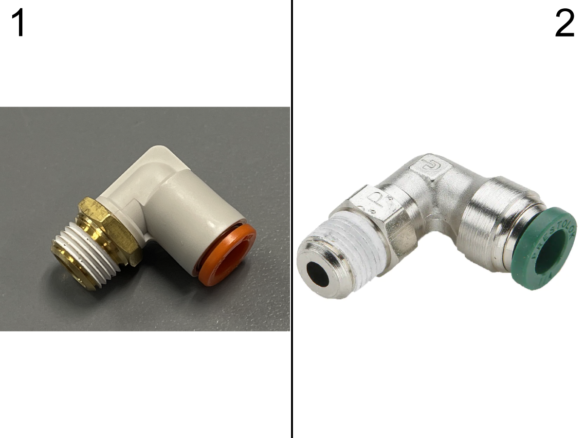
 Note: Depending on the build date of the machine. If PN: 58-3050 FITG PC1/4F NPT1/8M 90 STL is installed on the oil injector. Replace the fitting with PN: 58-2195 FITG PC1/4F NPT1/8M 90 STL.

Spindle Cap Identification

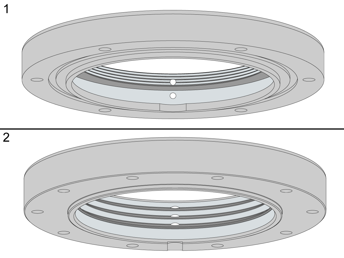
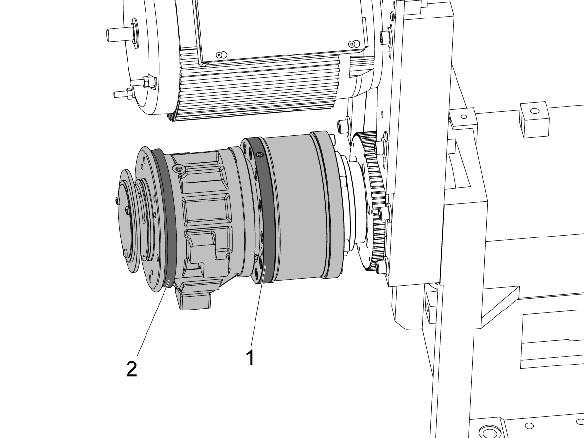
Depending on machine vintage the front spindle retainer cap of your machine may be the hollow design [1] or the updated current solid design [2].

Important : If your machine has the hollow cap design ensure that it is upgraded to the solid cap design when replacing the spindle since it deforms by design and cannot be used for multiple spindles.

 Note: Refer to the Lathe - Spindle Solid Front Cap – Replacement procedure to install/upgrade to a solid front cap if needed.

Removing the Old Spindle

1

  • Zero return the machine to allow for plenty of access to the spindle head
  • Power off and lock out the machine
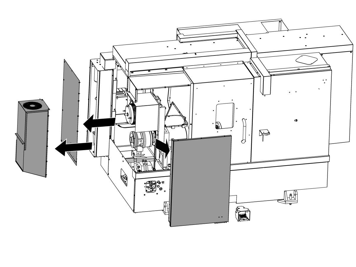
  • Remove the coolant collector box, rear, and front panel to gain access to the spindle head

2

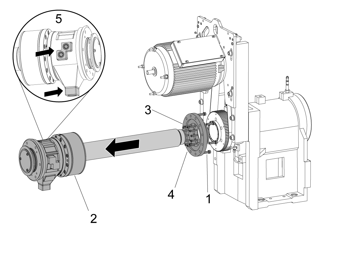
  • Remove the anti-rotation bracket that seats around hydraulic union drain hose
  • Lock the spindle to prevent it from rotating
  • Break the screws [1] loose that connect the adapter to the union
  • Disconnect the hydraulic lines [5] from the hydraulic union [2]. Note the clamp/unclamp hose and port orientation
    •  Note: Have plugs or baggies and rubber bands to cover the hoses to prevent hydraulic fluid from coming out and debris from getting in.  Keep the hoses pointed up and tucked away on the side of the spindle to prevent fluid from coming out
  • Remove the screws and slowly remove the union and drawtube assembly
    • Caution: The union is heavy and if dropped  it could receive permanent damage
    • Have a box or table nearby with padding to lay the union in and support the drawtube
  • Remove the adapter screws [3] that secure the adapter [4] to the spindle shaft.
  • Remove the adapter [4] (See ST Adapter Replacement Guide if the adapter must be replaced as well)
    • Early machines have a clearance fit adapter that will easily be removed once the screws are broken loose
    • Later machines (ST-15 through ST-30  11/2018 and after;  ST-10 02/2017 and after) will have a sweat fit adapter
      • To remove sweat fit adapters use a torch and evenly heat the outer diameter of the mating surface
      • After a few minutes begin gently dislodging the adapter until it slips free
      • Do not pry or cause damage when removing - you will need to re-use this part
      • Let it cool down slowly to prevent distortion

3

  • Break loose the motor mount plate screws [4]
  • Loosen the nut on the tensioner block [3] and loosen the belt tension on the belt by turning the socket head cap screw (SHCS) counter-clockwise
  • Remove the belt from the pulley
  • Break loose the drive sprocket [1] screws
  • Remove the drive sprocket
    • Some machines have a sweat fit drive sprocket that will clear the housing bore when the spindle cartridge is removed.  These won't need to be removed.

4

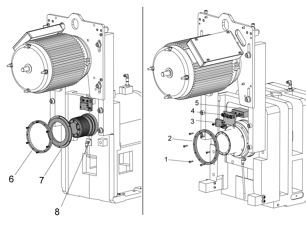
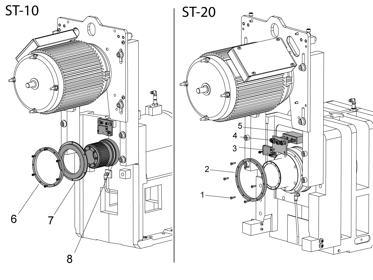
  • Removing the encoder ring [2]:
    • The encoder ring [2] could be a loose fit to the bearing lock on the rear of the spindle as shown, an encoder mount that mounts to the bearing lock, or a sweat fit to the bearing lock or encoder mount
    • On ST-30 gearbox and ST-35/gearbox machines the ring mount may be for the home switch instead. (machines 03/2019 and after). On these machines the non-contact encoder will be on the output of the motor shaft. In this case leave the encoder on the motor but remove the ring on the spindle for the proximity switch.
  • If loose fit: loosen screws [1] and carefully remove the ring without causing damage to the outer ring shield
  • If sweat fit: remove the screws [1] from the through holes, install the screws to the threaded hole pattern and use them as jacking screws to evenly remove the encoder ring
    • Use a stone to smooth out the marks left from the jacking screws when you're done
  • Temporarily remove the read-head [3] (or proximity switch), read-head plate [4], and bracket [5]
  • Secure the read-head out of the way to the motor mount brace with a cable tie
  • If there is an encoder ring mount: Heat the mount lightly with a torch, mount not to exceed  (230 °F, 110 °C ), and gently tap off the same way the sweat fit adapters are removed

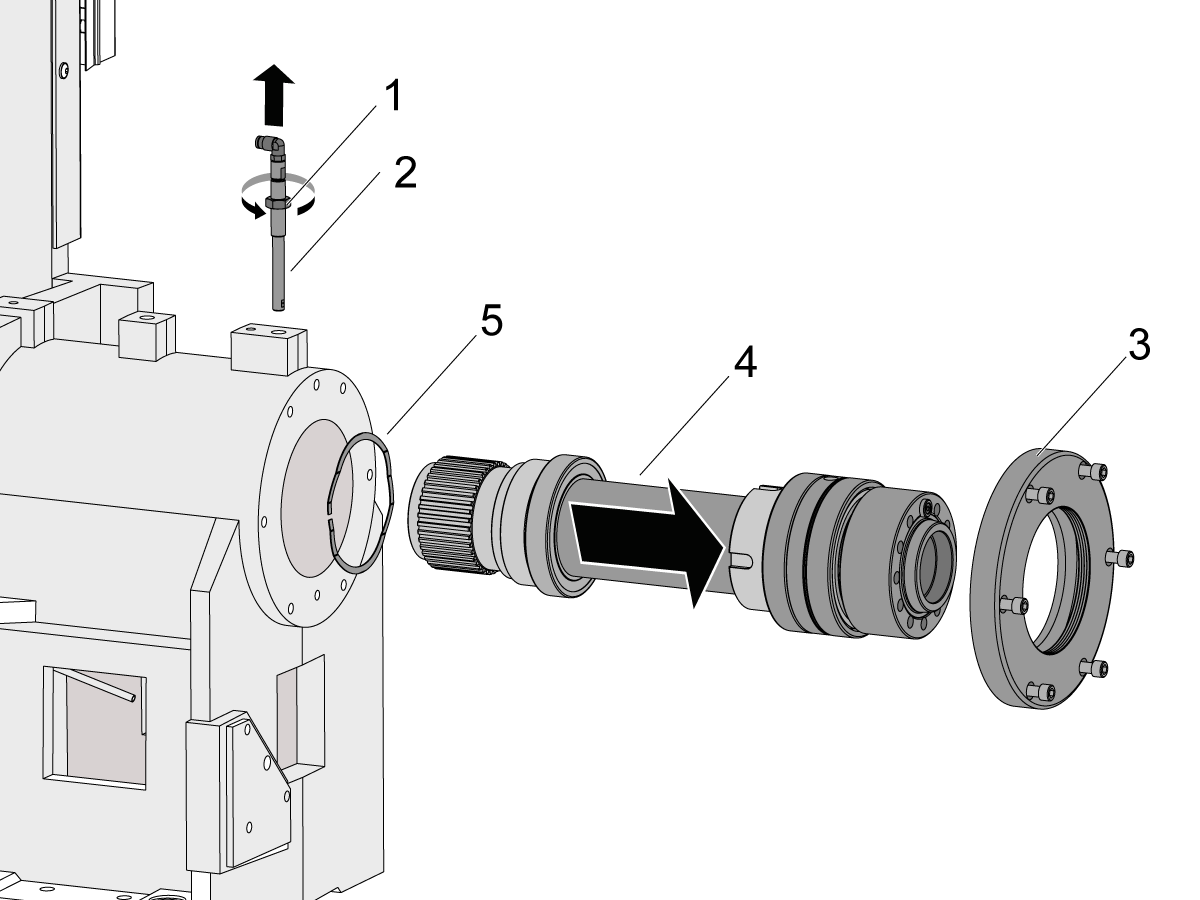
5

Warning: Clean all areas of the spindle head assembly before removing any spindle components. This includes the spindle oil injector, front cap, top of the spindle head casting, and oil lubrication hose. This is done to not introduce contaminants when removing and replacing the spindle.

  • Break loose the nut [1] on the spindle oil injector nozzle [2]
  • Remove the nozzle [2]
  • Break loose the spindle retainer cap [3] screws
  • Remove the retainer [3]
  • Remove the spindle cartridge [4]
    • Tap the rear of the cartridge with a plastic mallet to break it loose from the spindle bore
    • Place a strap around the spindle cartridge and use a hoist to help support the load as you remove it
  • Pack the spindle in the packaging the new spindle came in to return it if it is under warranty
  • Some spindles have a wave spring [5] or o-ring in the rear of the spindle housing bore
  • Remove this and clean it if necessary
  • Clean the spindle housing bore with scotch brite and alcohol
  • Wipe out all debris
  • Wipe with a light coat of SHC 625 or Mobil 5W20 oil or equivalent
  • Coat the o-ring or wave-spring with a light coat of Red-I grease or equivalent
  • Re-install to the rear of the spindle bore
    • Wave-spring goes pointed side down into the shoulder

Install New Spindle

1

Depending on the build date of the machine. If PN: 58-3050 FITG PC1/4F NPT1/8M 90 STL[1] is installed on the oil injector. Replace the fitting with PN: 58-2195 FITG PC1/4F NPT1/8M 90 STL[2].

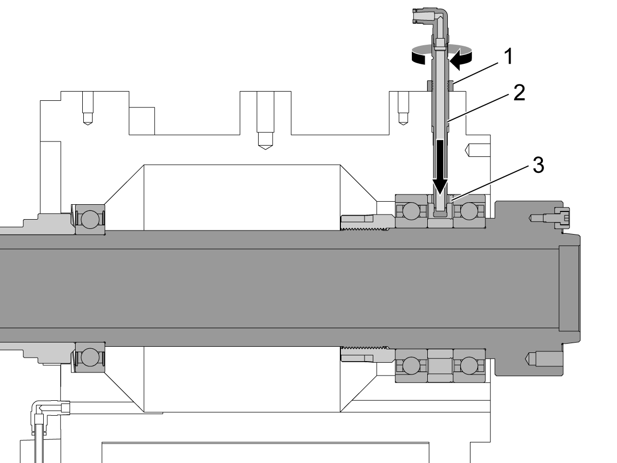
2

  • Install the new spindle cartridge using a strap and hoist
    • A 2"x2" piece of wood (or other soft material) placed through the bore of the spindle can be useful in order to get the rear of the cartridge to seat square in the bore of the spindle head
  • You must align the hole in the bearing spacer [3] with the injector nozzle [2] hole in the casting
  • Install the injector nozzle [2]
    • Thread it all the way in, then back it out one to one and a half turns
    • If it can't thread all the way in then the hole in the bearing spacer is not aligned correctly.  You will need to pull the cartridge out and re-align.
  • Adjust the injector nozzle so the flat side is facing forward (towards the chuck side of the spindle)
  • Hold in place and tighten the nut [1]

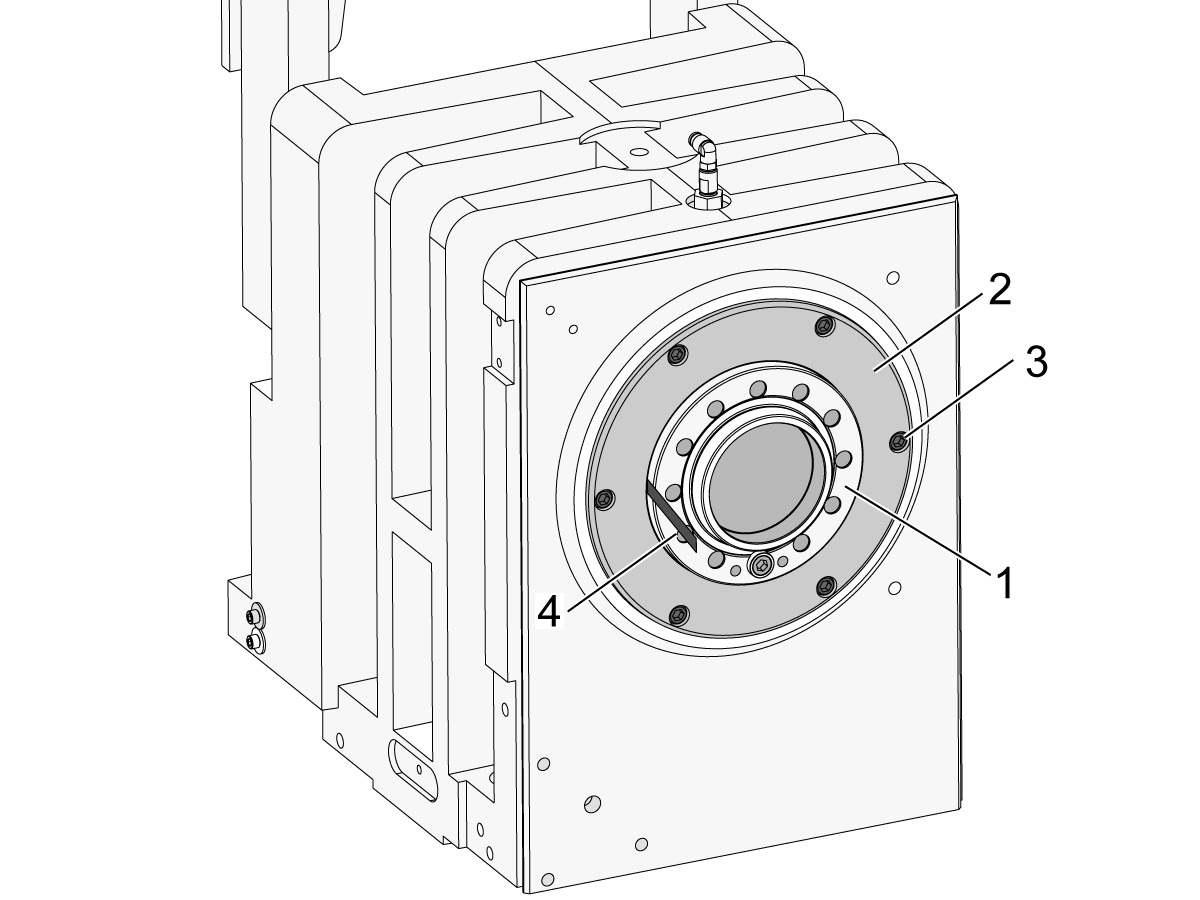
3

  • Install the spindle retainer cap [2]
  • Snug the spindle cap screws [3]
  • Use a .001" shim [4] between the cartridge and the spindle retainer [2]
  • Tap the spindle retainer with a plastic mallet until the shim clears every section of the cartridge
  • Torque the retainer screws [3] in a star pattern.
    • Note : You may need to start at a 1/3 of the torque value and torque them down 3 times. Torquing down all the way the first time may displace the retainer cap and require it to be reset.
  • Sweep between the cartridge and the retainer cap one last time to verify the .001" shim has clearance all the way around [4]

 Important : Ensure that a Spindle Deflection Test is conducted to verify spindle pre-load.

Note : Refer to Spindle Cap Identification section.

4

  • Install the non-contact encoder ring [2]/[6] or proximity switch ring:
  • If the ring is slip fit, install and indicate in to .001" TIR
  • If the ring is sweat fit it may mount directly to the spindle bearing lock as with the ST-20 OR it may mount to an encoder ring mount [7] that then mounts to the pulley [8] as with the ST-10
  • For the ST-10 mount, install the ring [6] to the mount [7] first:
    • Heat the encoder ring on a hot plate to a max temperature of 248 °F (120 °C) 
    • Install to the ring mount, press evenly to seat it square into the shoulder
    • Heat the ring mount and encoder ring assembly to a max temperature of  248 °F (120 °C) for 20 minutes
    • Install the assembly to the pulley shoulder, press evenly to seat it square into the shoulder
  • Once the ring has cooled down check the outer diameter runout NTE 0.001" TIR
  • Install the read-head bracket [5], read-head plate [4], and read-head [3]
  • Set the gap using the read-head/ring shim

5

  • Installation of the pulley is reverse of removal (ST-15/20/30/40). The ST-10 model from 08/2016 and onward, have sweat fit pulleys that do not need to be removed.
  • Slip the pulley onto the spindle shaft and snug the screws [1] into the spindle bearing lock [2]
  • Indicate the pulley, NTE .001" TIR
  • Torque the pulley screws [1]
  • Install the belt to the spindle and motor pulleys
  • Tension the belt by tightening the socket head cap screws [3] (SHCS) in the clockwise direction
    • Tighten both screws evenly until belt tension is achieved
    • Check belt tension with the Gates Sonic Meter, reference the Belt Tension Specs
    • Tighten the nut on each screw once belt tension is set
    • Verify the belt tension is correct
  • Torque the motor mount screws [4]
  • Check the gap between the encoder and read-head to make sure the shim still drags lightly between both surfaces

6

  • A hot plate will work best to uniformly heat the adapter
    •  Caution: Do not exceed 248 °F (120 °C) when heating the adapter
  • Place the adapter smaller diameter face down on the hot plate
    •  Caution: Be sure to use high temperature heat resistant gloves when sweat fitting the adapter
  • When you install the adapter you must move quickly as the aluminum will cool fast
  • With the adapter at about 248 °F (120 °C) on the hot plate - take one screw [1] and put it into the adapter washer [2] to have it ready
  • With gloves on, using both hands, take the adapter and quickly slip it onto the shaft
  • Press evenly on both sides, until you feel it seat  
  • Rotate it until the hole patterns line up
  • Take the screw and adapter washer and quickly run down the one screw into a hole
  • Quickly run the rest of the screws down in a star pattern
  • Torque the screws in a star pattern to ensure the adapter seats
    • Haas Torque Chart
  • Then break the screws loose but leave them snug while the adapter cools
  • Torque screws again once the adapter has cooled
  • Once cooled measure the inner radial runout [3], not to exceed 0.001"
  • Measure the axial runout [4], not to exceed 0.0005"
    • Production Tip: If you find that you're having a hard time getting the adapter to seat and have acceptable runout, then try the following.  After you slip the hot adapter on the shaft, snug all the screws down, and then lightly indicate the adapter on the inner radius [3] while using a plastic mallet on the outer diameter. When the runout is within spec, slowly torque all of the screws down in a star pattern being careful not to induce runout.

7

  • Install hydraulic union:
  • A limited number of ST-10's have a sweat fit from the adapter to the union.  If you have this condition you can heat the adapter with a torch for about 3-5 minutes until the bore grows enough to allow the hydraulic union to slip in.
  • All other lathes - install the union and snug the screws
  • Indicate in the steel strip [1] NTE 0.0005" TIR
  • Check the deflection measurement [2] by placing the indicator on the non-rotating body of the union and then rotate the pulley.  The deflection should be less than 0.001".
  • Re-attach the clamp/un-clamp hoses and the drain hose
  • Warning: Do not over tighten or you could crack the aluminum assembly

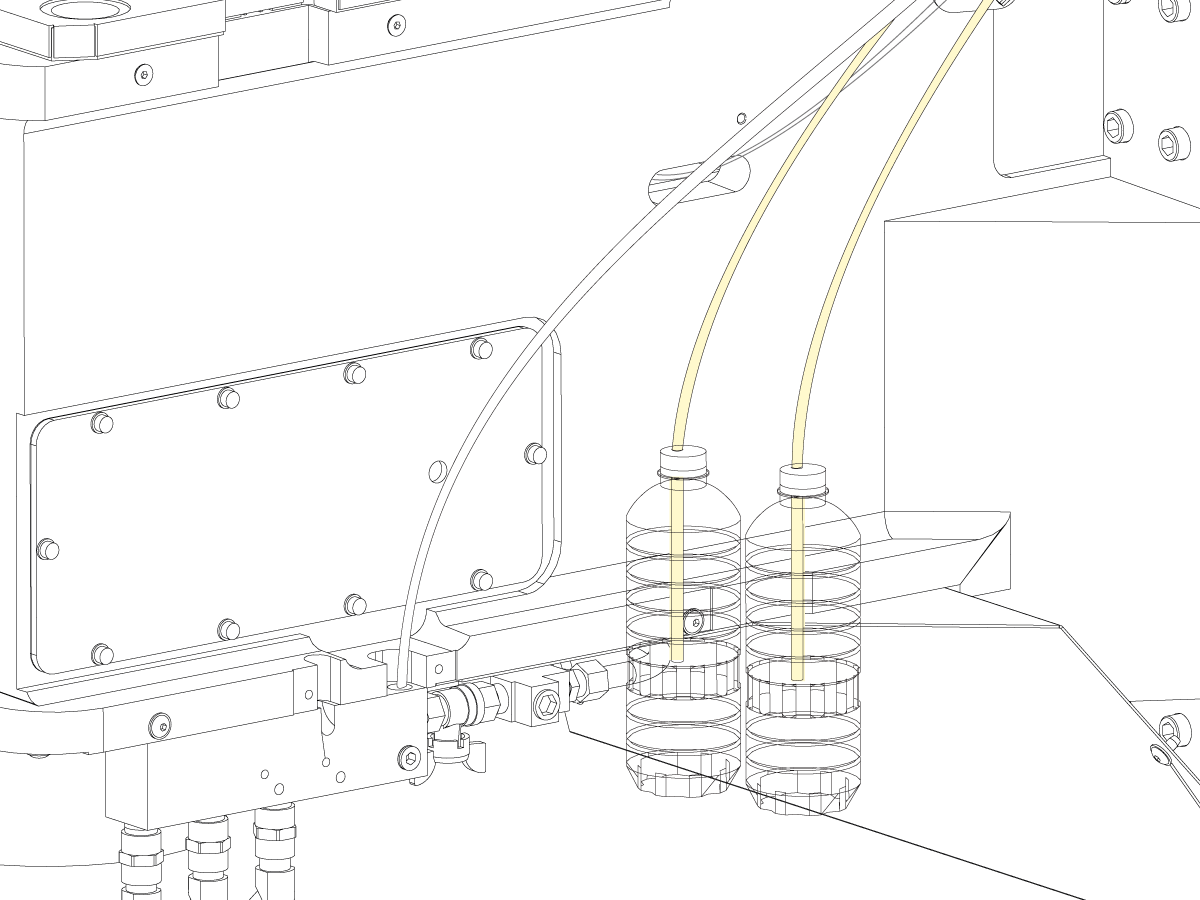
Verify Spindle Lubrication - Bottle Test

After replacing the spindle you will want to make sure it gets adequate oil.

For testing, refer to the link below.


Spindle Lubrication Test

Note: If you have an old style oil pump that does not have sight glasses, then you must install the sight glass upgrade.

For installation, refer to the link below.

Drip Sight Glass Installation

Check Spindle Vibration

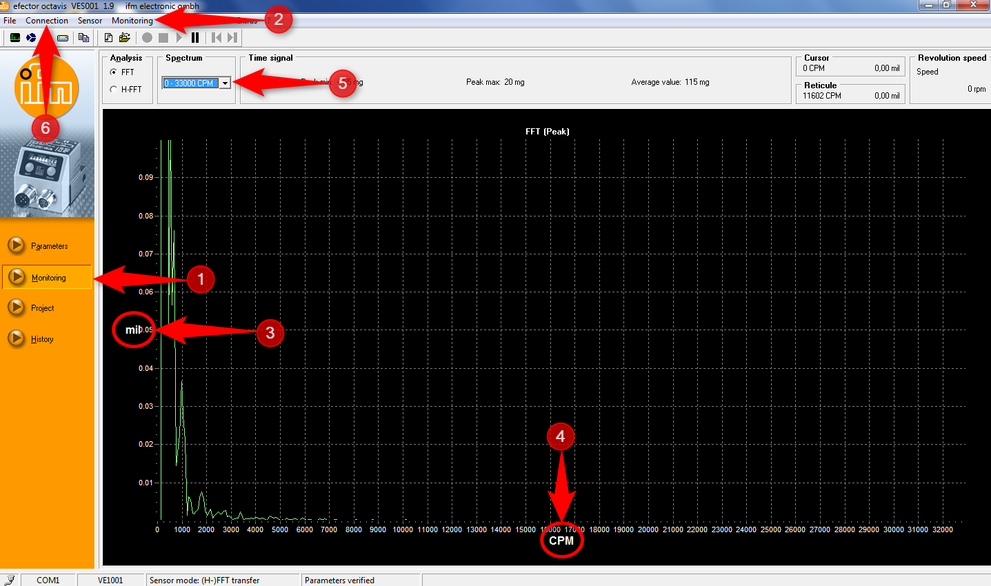
  • Run a spindle vibration test
  • Check results against Lathe Spindle Vibration Tolerances
  • Troubleshoot bad results with Lathe Vibration Troubleshooting Guide
    • Some lathes have balancing holes for set screws on the adapter plate or the pulley face
    • Use these holes to reduce unnecessary vibration only after verifying all components meet specified runouts
  • If the spindle passes, re-install enclosure, and the procedure is complete

4.2 Lathe Spindle - Troubleshooting

Recently Updated

Lathe Spindle - Troubleshooting Guide


TG0093

Revision B - 6/2026

Lathe Spindle Inspection Report

Download and fillout the lathe spindle Inspection Report Checklist below before replacing any parts.

Lathe Spindle - Service checklist

Section 1: Introduction

NOTE: Although this troubleshooting guide is for the main spindle many of the symptoms in the symptoms table can be used for the sub spindle. 

The most common problems with a lathe spindle are vibration, noise and surface finish. 

Vibration is caused by runout. Look first at your workholding and your material. Ensure the chuck body or collet nose runs true; that your jaws are bored correctly; that your material isn’t running out. If you are bar feeding make sure the liner fits the material properly. If you still have a problem check runout of the hydraulic closer, the brake disc and all adapters.

If you haven’t fixed noise by addressing vibration above then the most likely cause is the drive belt. Make sure tension is correct; that the belt is in good condition; that shaft alignment is good and the belt isn’t forced against a pulley flange. 

If you have a surface finish problem that hasn’t been solved by the above then check the application: speeds, feeds, tool tip alignment, coolant flow, etc. also check machine alignments. 

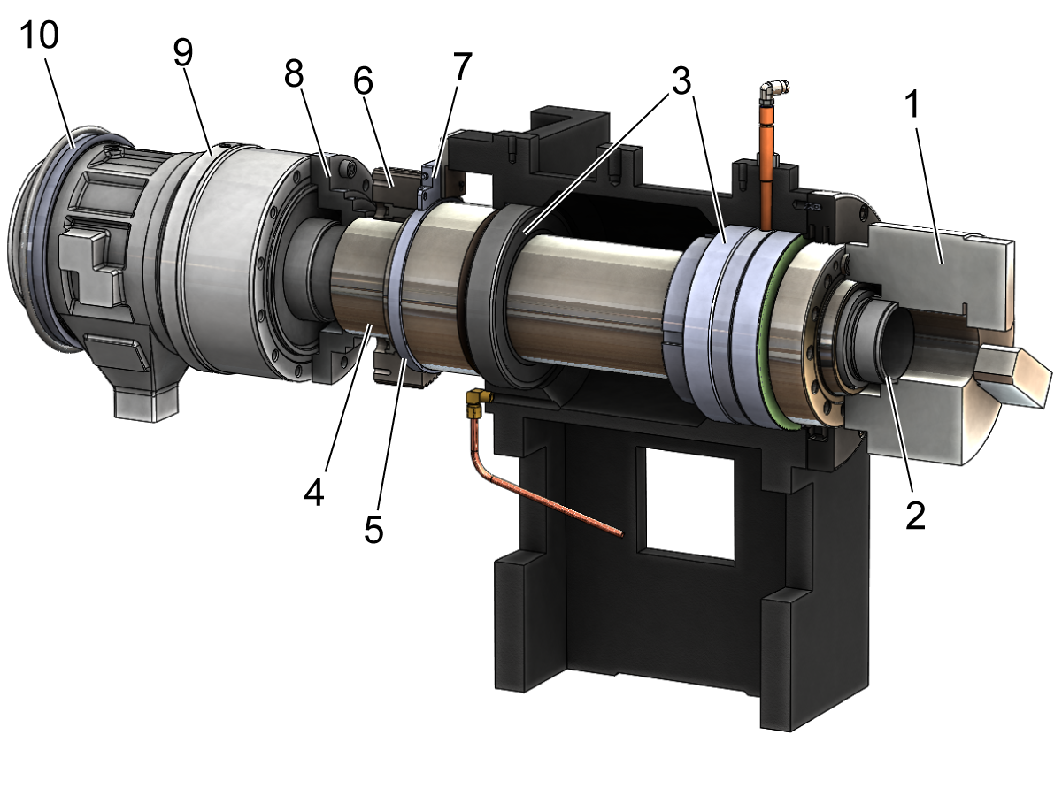
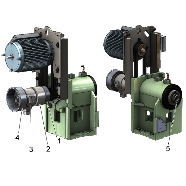
For more lathe spindle symptoms please view the troubleshooting table below. For reference, the spindle drivetrain consists of the following:

  1. Chuck or Collet
  2. Drawtube
  3. Bearings
  4. Spindle Shaft
  5. Non-Contact Encoder Ring
  6. Sprocket
  7. Non-Contact Encoder Read-Head
  8. Adapter
  9. Hydraulic Actuator
  10. Coolant Collector

Symptom Table

Symptom Possible Cause Corrective Action

Vibration

Alarm 966 Excessive Tool Imbalance

Workpiece runout Indicate in workpiece runout depending diameter and spindle speed
Long bar stock or liner adapters with a poor fit Do not run bar stock past the hydraulic union stop. Only use tight fit liner adapters (Big Bore). 
Big Bore Spindle Liner O-Rings do not center Liner to drawtube and union.

For the following Liner Kits replace both O-Rings with 93-3772. See Lathe - Spindle Liner O-ring - Replacement

  • LINER KIT 4.00 12
  • LINERKIT-4-ST40
Spindle drivetrain misalignment Verify each component is within specified runouts - see Section 2
Spindle speed is running in a resonance frequency of the machine Speed up or slow down the spindle by 10% until vibration or surface finish improves
Spindle imbalance Run a vibration analyzer test.  Balance out high vibration using set screws in the union adapter - see Section 3
Motor vibration Run the motor without the belt to isolate motor vibration from spindle vibration
Damaged spindle bearings Run a vibration analyzer test to determine bearing health - See Section 6.  Test the spindle lubrication system - See Section 5 and the  Spindle Minimum Lubrication System Troubleshooting Guide
Encoder feedback Test the spindle to see if vibration goes away when you cut machine power and allow the spindle to coast to a stop
Spindle retaining ring alignment Sweep with a .001" shim between the spindle shaft nose and ring to check gap - adjust ring if needed
The Main Processor PCB standoff hardware is loose or the Control Cabinet mounting hardware is loose or causing a bind.   Tighten the Main Processor PCB standoff hardware. Loosen the Control Cabinet mounting hardware, snug the hardware, then torque down the hardware.

ST-35Y only:

Machine missing spindle motor stabilizer.

See Lathe - Spindle Motor Stabilizer - Installation to add stabilizer.

CL-1 only:

The spindle was commanded to turn when the spindle lock pin was engaged. This deformed the lock collar so that the deformation contacts the bore of the spindle housing when the spindle rotates.

The lock collar cannot be replaced. The entire spindle assembly will need to replaced if the lock collar is damaged enough to contact the spindle house and cause vibration while the spindle rotates. See the Chucker Lathe Operator's Manual - Operation section for more information on operating the workholding.
Bearing Noise Ball bearings and cage sound like they are skating around the races - caused by too little pre-load Run a vibration analyzer test to determine bearing health.  Inspect the spindle retaining ring step (that presses on the outer bearing race) for permanent deformation - see Section 6
High pitched whining noise - caused by too much pre-load Run a vibration analyser test to determine bearing health - see Section 6
Clicking noise - caused by a brinelling of the bearing which occurs when there is an impact to the spindle Run a vibration analyzer test to determine bearing health - see Section 6
Belt Noise Tooth wear, tensile break, incorrect belt tension See Drive Belt Troubleshooting Guide and Section 4

Alarm 9918 Serial Encoder Fault

Alarm 9959 Serial Encoder Cable Fault

Alarm 4.103 Spindle Axis Servo Error too Large

Encoder gap incorrect See Spindle Encoder Troubleshooting Guide and Section 7
Encoder ring damaged
Encoder cable damaged or loose
Alarm 174 Tool Load Exceeded Insert worn Inspect and replace insert if necessary
Tool load limit incorrect View the Advanced Tool Management (ATM) tab to adjust user defined tool load limit
Aggressive feedrates Adjust your program for a more conservative feedrate
Alarm 4.116 S (SPINDLE) SPINDLE ORIENTATION FAULT The workholding has been replaced and the spindle load parameter is not set correctly Follow Setting 413 Procedure to set the Main Spindle Load Type parameter correctly. 
Alarm 12.116 SS (SECONDARY SPINDLE) ORIENTATION FAULT Alarm happens when the sub-spindle to orient with M119 Check on the mocon tab channel 14 [SS] home switch and move the spindle slowly by hand and verify the bit changes, if it does not check if the home switch or trip flag works properly. 
The spindle orient position changes after powering down the machine and powering back up. At power up if the spindle home switch is located exactly in the middle of the two encoder Z pulse locations. Depending on the first spindle rotation direction after booting up the machine, the spindle may pick different encoder Z pulse as a reference for the spindle Z pulse which can cause the spindle orient to be inconsistent. Update the machine to the latest software and configurations.
  • Non-repeatable spindle orients between power cycles.
  • C-Axis engagement alarms.
  • Re-running taps and threads between power cycles.

ST-15/20/25 lathes and variants built from 8/1/2022 switched the 5.6" Non-Contact Encoder mounted on the spindle to a 3" NCE on the motor output shaft. A home switch was added to the spindle to ensure repeatable spindle orientation at power up. This home switch was not enabled by parameters for these machines.

The home switch was also not enabled by parameters for all NGC ST-50/55 machines built 1/1/2021 and later.

Update the machine to the latest software version and download and load the latest configuration files from the service portal.

HSG-A  02-7-2023

The machine experiences issues during spindle deceleration, spindle orientation with M19, the C-axis engaging, or the following alarms after changing to a new job with a large or small workholding or a large or small part. Alarms: 650 DC BUS OVER VOLTAGE, 4.994 S (SPINDLE) AMPLIFIER OVERLOAD, 4.116 S (SPINDLE) SPINDLE ORIENTATION FAULT, 9989 C AXIS FAILED TO ENGAGE. The machine parameters are not tuned for the part or workholding installed.

Machines with Alarms: 650 DC Bus Over Voltage / 4.994 S see Section 8.

Follow Setting 413 Procedure to set the Main Spindle Load Type parameter correctly.

Setting 413 is available for machines with the New Mocon enabled and with software version 100.21.000.1111 or greater. The New Mocon, is a Motion Control algorithm that uses more parameters to better control the axis of the machine. Press Diagnostic and navigate to the System tab. The Mocon version will be in the Software section. Mocon version 1.16  .S. is the New Mocon. If the Mocon Version is 1.16 or 1.16  .K, then you have the old Mocon Version.

Note: At this time we are not updating machines to New Mocon in the field.

Alarm 4.108 S (SPINDLE) AXIS SERVO OVERLOAD
A large amount of constant surface speed (CSS) can cause acceleration/deceleration. That constant acceleration/deceleration causes the load meter to go above 100%. If the load meter remains above 100% for too long, you will get this alarm.  This can also happen if the average load over time is above 100%. Change the roughing constant surface speed (CSS) to a fixed spindle speed.
Alarm 12.9107 SS (2ND SPINDLE) CHECK YOUR HOME SWITCH Loss of ability to command finishing spindle on ST lathes. Verify that sub-spindle home switch is operational. Refer to Finishing Spindle section below.

Section 2: Spindle Drivetrain Alignment

 Note: For illustration purposes the chuck is removed. The chuck should not be removed to perform the following checks.
 
Check the runout at the following locations and adjust if necessary:
  • Radial runout of the hydraulic actuator rotary body on the steel strip [2] - NTE (not to exceed) 0.0005" TIR (total indicated runout)
  • Radial runout of the hydraulic actuator adapter on the inner diameter bore [1] - NTE  0.001"TIR 
  • Radial runout of the inner diameter of the drawtube [5]
    •  If more than 0.010" TIR this could indicate that the drawtube is not perpendicular to the bore of the hydraulic actuator piston
    • This causes excessive vibration and the drawtube would need to be re-installed
  • Measure the deflection on the side of the hydraulic actuator static body [3] or the coolant collector [4] while rotating the spindle. If more than .0015" TIR is measured, this will induce excessive vibration. You can attempt to loosen the screws that secure the actuator to the adaptor plate and lightly tap the rotary body of the actuator until you reduce the deflection runout on the static body. Use the vibration analyzer to see how this changed the vibration displacement and velocity plots.
  • Check the gap between the retaining ring (front spindle cap) and the spindle shaft nose using a 0.001" shim. To Align:
    • Break loose the retaining ring bolts
    • Tap the retaining ring to set the gap to 0.001"
    • Gradually tighten the bolts in a star pattern until they are torqued per the Haas Torque Chart
    • Verify the gap using a 0.001" shim

Section 3: Spindle Balancing

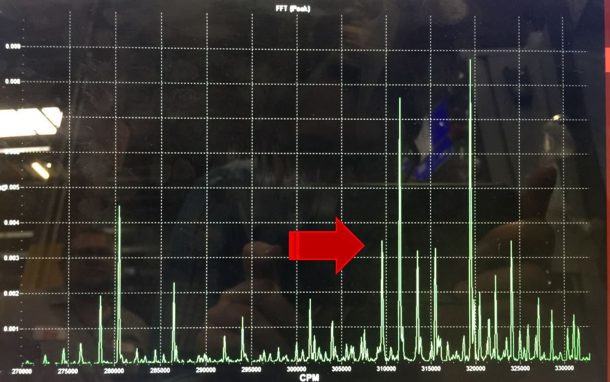
Lathe spindle balancing is applicable to re-boot ST machines. Use the Octavis Vibrational Analyzer program to view the displacement plot as you attempt to balance the spindle. If you do not have set screws to balance the spindle you can order kit 93-2867 .

  • Vibration Analysis - Ethernet Interface
  • Vibration Analysis - RS-232 Interface

There are balancing holes provided on the actuator adapter [1]. The goal is to make the displacement spike the lowest possible value at whichever speed the test is being run at.

  • If the Displacement spike decreases when a weight is added, then continue to increase the amount of weight inserted into the hole until the spike gets to the lowest possible value. Check that moving the weight or adding weight to the surrounding holes does not lower the spike as well.
  • If the Displacement spike increases, then remove weight and move to the next balancing hole on the union adapter until the Displacement spike reaches the lowest possible value. Experiment with small and large weights to get the best results.

Section 4: Belt Noise

Inspect the condition and tension of the spindle drive belts. A belt that is too tight or too loose will induce undesirable vibration. ST-30 NGC gearbox machines with prematurely worn belts will need the ST-30 Gearbox Non-Contact Encoder Upgrade Kit

Refer to the Drive Belts Troubleshooting Guide for more information.

Section 5: Lubrication System

Verify the spindle is getting adequate lubrication by completing a bottle test

  • Insufficient oil will cause premature bearing failure that will induce vibration
  • Excessive amount of oil will cause the bearings to overheat and prematurely fail

Refer to the Lubrication System Troubleshooting links below:

  • Mechanical Bijur Lube Pump - Troubleshooting Guide
  • Spindle Minimum Lubrication System - Troubleshooting Guide

Section 6: Bearing Noise

Use the Octavis Vibration Analyzer to monitor bearing health.  Place the accelerometer on the side on the spindle head retaining ring or motor mount.

  • Run a vibration test throughout the machine's entire RPM range while taking note of the following:
    • Cage rattle - sounds like the ball bearings are skating on the races or the cage is rattling - [Velocity Plot 1]
    • High pitched squeal or screech caused by a ball flaw or damaged race- [Velocity Plot 2]
    • If you encounter an RPM where the machine makes noise, check the velocity plots for signs of bearing damage or cage rattle
    • Harmonic nodes where the machine displacement is amplified - these look like sudden increased in value spikes on the displacement plot.  Do these harmonic nodes correlate to the RPM where the machine is vibrating? If so - the machine is struggling with a resonant frequency.
  • If you note any signs of bearing damage, perform the following checks to verify the mechanical soundness of the spindle:
    • Check the machine history for any signs of a machine crash
    • Check the fore and aft movement of the spindle with an indicator on the spindle nose.  The movement should be less than 0.0005" if pushing by hand and the indicator should return to zero within 0.0001"
    • Check the axial and radial runout of the spindle nose.  Runout should be less than 0.0005" TIR
  • Corrective action includes:
    • Attempting to increase or decrease spindle speed in 10% intervals to reduce the affect of resonant frequencies
    • Balancing the spindle at the speed in which the owner most uses the spindle to reduce the displacement spike and reduce noise seen on the velocity plots
    • Verifying the spindle receives adequate oil (Section 5)
    • Check machine level and verify the machine is not too high up on the leveling feet
    • Check the step on the spindle retainer to see if it has permanent deformation.  The retainer must be removed to perform this check.
  • If nothing reduces vibration then the spindle may be at the end of its life and need to be replaced.  Contact Haas Service for approval if within warranty.

Section 7: Motor Encoder Feedback

The Haas spindle drive system is a Closed Loop System and requires continuous feedback from the encoder to precisely control the spindle speed via the motor. Inadequate encoder feedback could cause vibration and noise in the spindle drivetrain. Test the encoder feedback by turning the power to the machine off while running the spindle and let the spindle coast. If the vibration goes away when power is off, then troubleshoot the Encoder / Encoder belt / Wye-Delta Contactor / or Vector Drive.

  • If the machine is equipped with the non-contact spindle encoder, then check the read head alignment with the provided shim (incorrect read head alignment could cause unreliable feedback).

For Encoder troubleshooting information refer to the Spindle Encoder - Troubleshooting Guide.

For Vector drive troubleshooting information refer to the Vector Drive - Troubleshooting Guide.

For Belt troubleshooting information refer to the Drive Belts - Troubleshooting Guide.

Section 8: Lathe Spindle Inertia Load Type Setting

Machines that experience alarm 650 / Alarm 4.994 will need to do the following:

  1. Remove the chuck from the lathe
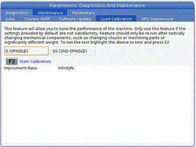
  2. Run the load calibration
  3. Take an error report and provide it to Haas Service

Note: Refer to the Lathe - Spindle Inertia Load Type Setting for information regarding the load calibration. 

Finishing Spindle : Alarm 12.9107

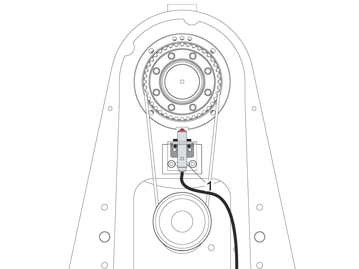
Haas Finishing spindles used on ST series machines use a home switch unlike secondary spindle in DS series lathes.

Remove the sheet metal enclosure and examine functionality of home switch [1].

Refer to Proximity Sensor - Troubleshooting Guide for more detail.

Setting 413 – Main Spindle Load Type

Setting 413 is available for machines with the New Mocon enabled and with software version 100.21.000.1111 or greater. The New Mocon, is a Motion Control algorithm that uses more parameters to better control the axis of the machine. Press Diagnostic and navigate to the System tab. The Mocon version will be in the Software section. Mocon version 1.16  .S. is the New Mocon. If the Mocon Version is 1.16 or 1.16  .K, then you have the old Mocon Version.

Note: At this time we are not updating machines to New Mocon in the field.

Recently Viewed Items

You Have No Recently Viewed Items Yet

Feedback
Haas Logo

Haas Delivered Price

This price includes shipping cost, export and import duties, insurance, and any other expenses incurred during shipping to a location in France agreed with you as a buyer. No other mandatory costs can be added to the delivery of a Haas CNC Product.

KEEP UP WITH THE LATEST HAAS TIPS AND TECHNOLOGY...

Sign up now!   

HAAS TOOLING ACCEPTS THE FOLLOWING:

  • Service & Support
  • Owners
  • Request Service
  • Operator Manuals
  • Haas Parts
  • Rotary Repair Request
  • Pre-Install Guides
  • Shopping Tools
  • Build & Price a New Haas
  • Available Inventory
  • The Haas Price List
  • CNCA Financing
  • About Haas
  • Accessibility Statement
  • DNSH Statement
  • Export Compliance
  • Careers
  • Certifications & Safety
  • Contact Us
  • History
  • Terms & Conditions
  • Haas Tooling Terms & Conditions
  • Privacy
  • Warranty
  • Haas Community
  • Haas Certification Program
  • Haas Motorsports
  • Gene Haas Foundation
  • Haas Technical Education Community
  • Events
  • Join the Conversation
  • Facebook
  • X
  • Flickr
  • YouTube
  • LinkedIn
  • Instagram
  • TikTok
© 2026 Haas Automation, Inc – CNC Machine Tools

This site is protected by reCAPTCHA and the Google Privacy Policy and Terms of Service apply.

2800 Sturgis Rd., Oxnard, CA 93030
Toll Free: (888) 817-4446 / Fax: 805-278-8554