My Haas Welcome,
!
Haas Tooling MyHaas/HaasConnect Sign In Register Haas Tooling MyHaas/HaasConnect Sign Out Welcome, My Machines Latest Activity My Quotes My Account My Users Sign Out
Find Your Distributor
  1. Select Language
    1. English
    2. Deutsch
    3. Español - ES
    4. Español - MX
    5. Français
    6. Italiano
    7. Português
    8. Český
    9. Dansk
    10. Nederlands
    11. Magyar
    12. Polski
    13. Svenska
    14. Türkçe
    15. 中文
    16. Suomi
    17. Norsk
    18. الإنجليزية
    19. български
    20. Hrvatski
    21. Ελληνικά
    22. Română
    23. Slovenský
    24. Slovenščina
    25. 한국어
    26. 日本語
    27. Українська
  • machines Main Menu
    • Vertical Mills
      Vertical Mills
      Vertical Mills View All
      • Vertical Mills
      • VF Series
      • Universal Machines
      • VR Series
      • VP-5 Prismatic
      • Pallet-Changing VMCs
      • Mini Mills
      • Mold Machines
      • High-Speed Drill Centers
      • Drill/Tap/ Mill Series
      • Toolroom Mills
      • Pocket Mill
      • Compact Mills
      • Gantry Series
      • SR Sheet Routers
      • Extra-Large VMC
      • Double-Column Mills
      • 3+2 Positioning Machines
    • Multi-Axis Solutions
      Multi-Axis Solutions
      Multi-Axis Solutions View All
      • Multi-Axis Solutions
      • Y-Axis Lathes
      • 5-Axis Mills
    • Lathes
      Lathes
      Lathes View All
      • Lathes
      • ST Series
      • Dual-Spindle
      • Box Way Series
      • Toolroom Lathes
      • Chucker Lathe
      • Pocket Lathe
      • Haas Bar Feeders
    • Horizontal Mills
      Horizontal Mills
      Horizontal Mills View All
      • Horizontal Mills
      • 50-Taper
      • 40-Taper
    • Rotaries & Indexers
      Rotaries & Indexers
      Rotaries & Indexers View All
      • Rotaries & Indexers
      • Rotary Tables
      • Indexers
      • 5-Axis Rotaries
      • Extra-Large Rotaries
    • Special Series
      Special Series
      Special Series View All
      • Special Series
      • EU_Series_Redirect
    • Automation Systems
      Automation Systems
      Automation Systems View All
      • Automation Systems
      • Mill Automation
      • Lathe Automation
      • Automatic Parts Loaders
      • Automation Models
    • Desktop Machines
      Desktop Machines
      Desktop Machines View All
      • Desktop Machines
      • Desktop Mill
      • Desktop Lathe
      • Control Simulator, Standard
      • Control Simulator, Premium
    • Shop Equipment
      Shop Equipment
      Shop Equipment View All
      • Shop Equipment
      • Knee Mill
      • Haas Manual Lathes
      • Haas Saws
    • Fabrication Machines
      Fabrication Machines
      Fabrication Machines View All
      • Fabrication Machines
      • Laser Cutting Machines
      • CNC Press Brakes
    • QUICK LINKS Special Series  Special Series 
      EU SERIES EU SERIES BUILD & PRICE | PRICE LIST BUILD & PRICE | PRICE LIST In-Stock Machines In-Stock Machines WHAT’S NEW WHAT’S NEW YOUR FIRST CNC YOUR FIRST CNC
      SHOPPING TOOLS
      • Build & Price a Haas
      • Price List
      • Available Inventory
      • CNCA Financing
      WANT TO TALK TO SOMEONE?

      A Haas Factory Outlet (HFO) can answer your questions, and walk you through your best options.

      CONTACT YOUR DISTRIBUTOR >
  • Options Main Menu
    • The Haas Control Value Option Packages
      Value Option Packages
      Value Option Packages View All
      • Value Option Packages
    • Product Image Spindles
      Spindles
      Spindles View All
      • Spindles
    • Product Image Tool Changers
      Tool Changers
      Tool Changers View All
      • Tool Changers
    • Product Image 4th- | 5th-Axis
      4th- | 5th-Axis
      4th- | 5th-Axis View All
      • 4th- | 5th-Axis
    • Product Image Turrets & Live Tooling
      Turrets & Live Tooling
      Turrets & Live Tooling View All
      • Turrets & Live Tooling
    • Product Image Probing
      Probing
      Probing View All
      • Probing
    • Haas Chip & Coolant Management Chip & Coolant Management
      Chip & Coolant Management
      Chip & Coolant Management View All
      • Chip & Coolant Management
    • The Haas Control The Haas Control
      The Haas Control
      The Haas Control View All
      • The Haas Control
    • Product Image Product Options
      Product Options
      Product Options View All
      • Product Options
    • Product Image Tooling & Fixturing
      Tooling & Fixturing
      Tooling & Fixturing View All
      • Tooling & Fixturing
    • Product Image Workholding
      Workholding
      Workholding View All
      • Workholding
    • Product Image 5-Axis Solutions
      5-Axis Solutions
      5-Axis Solutions View All
      • 5-Axis Solutions
      • 5 Easy Steps to 5-Axis
    • QUICK LINKS Special Series  Special Series 
      EU SERIES EU SERIES BUILD & PRICE | PRICE LIST BUILD & PRICE | PRICE LIST In-Stock Machines In-Stock Machines WHAT’S NEW WHAT’S NEW YOUR FIRST CNC YOUR FIRST CNC
      SHOPPING TOOLS
      • Build & Price a Haas
      • Price List
      • Available Inventory
      • CNCA Financing
      WANT TO TALK TO SOMEONE?

      A Haas Factory Outlet (HFO) can answer your questions, and walk you through your best options.

      CONTACT YOUR DISTRIBUTOR >
  • Why Haas Main Menu
      Discover the Haas Difference
    • Why Haas
    • MyHaas
    • Education Community
    • Industry 4.0
    • Haas Certification
    • Customer Testimonials
  • Service Main Menu
      Welcome to Haas Service
      SERVICE HOME Operator’s Manuals How-To Procedures Troubleshooting Guides Preventive Maintenance Haas Parts Haas Tooling Videos
  • Videos Main Menu
  • Main Menu
    • View All
    • View All
    • View All
    • View All
      • HTEC Curriculum Support
      • Haas Value Option Packages (VOP) Journey
    • View All
      • Haas 10 kg Cobot Package
      • Cobot Kits
      • DC-1 Drill Center
      • CNC Sales News
      • Do More With Your Haas
    • View All
    • View All
      • contact-us-test
      • 4 - AUTOMATION SYSTEMS
      • Carousel-V2
      • expert test
      • Demo_Day_Trident-test
      • Link Test
      • image-sale-tag-test
      • article-list-test
      • Haas 25 kg Robot Package
      • test-algolia-page
    • View All
    • View All
    • View All
    • View All
      • calc-test
    • View All
    • QUICK LINKS Special Series  Special Series 
      EU SERIES EU SERIES BUILD & PRICE | PRICE LIST BUILD & PRICE | PRICE LIST In-Stock Machines In-Stock Machines WHAT’S NEW WHAT’S NEW YOUR FIRST CNC YOUR FIRST CNC
      SHOPPING TOOLS
      • Build & Price a Haas
      • Price List
      • Available Inventory
      • CNCA Financing
      WANT TO TALK TO SOMEONE?

      A Haas Factory Outlet (HFO) can answer your questions, and walk you through your best options.

      CONTACT YOUR DISTRIBUTOR >
  • Haas Tooling Main Menu
  • Haas Service Parts Main Menu

My Haas Welcome,
!
Haas Tooling MyHaas/HaasConnect Sign In Register Haas Tooling MyHaas/HaasConnect Sign Out Welcome, My Machines Latest Activity My Quotes My Account My Users Sign Out
Find Your Distributor
  1. Select Language
    1. English
    2. Deutsch
    3. Español - ES
    4. Español - MX
    5. Français
    6. Italiano
    7. Português
    8. Český
    9. Dansk
    10. Nederlands
    11. Magyar
    12. Polski
    13. Svenska
    14. Türkçe
    15. 中文
    16. Suomi
    17. Norsk
    18. الإنجليزية
    19. български
    20. Hrvatski
    21. Ελληνικά
    22. Română
    23. Slovenský
    24. Slovenščina
    25. 한국어
    26. 日本語
    27. Українська
×

Search Results

Web Pages

Images

    • <
    • 1
    • >

6 - CL - Operation

Chucker Lathe - Operator's Manual Supplement


  • 0 - CL - Table of Contents
  • 1 - CL - Introduction
  • 2 - CL - Legal Information
  • 3 - CL - Safety
  • 4 - CL - Installation
  • 5 - CL - Control Icons
  • 6 - CL - Operation
  • 7 - CL - G-Codes
  • 8 - CL - M-Codes
  • 9 - CL - Settings
  • 10 - CL - Maintenance

Go To :

  • 6.1 CL - Machine Power-On
  • 6.2 CL - Workholding
  • 6.3 ATT8 Turret Operation
  • 6.4 ATT8 Tool Change Recovery
  • 6.5 Bar Pusher - Load Bars
  • 6.6 Bar Pusher - Setup
  • 6.7 Bar Pusher - Operation
  • 6.8 Bar Pusher - Change Bars
  • 6.9 CL - Parts Catcher Setup
  • 6.10 CL - Parts Catcher Operation

6.1 CL - Machine Power-ON

CL - Machine Power-On

Follow this procedure to turn on a Chucker Lathe for the first time.

Before you do this procedure, make sure that possible crash areas, such as the spindle, and tool changer are clear and that all shipping brackets have been removed.

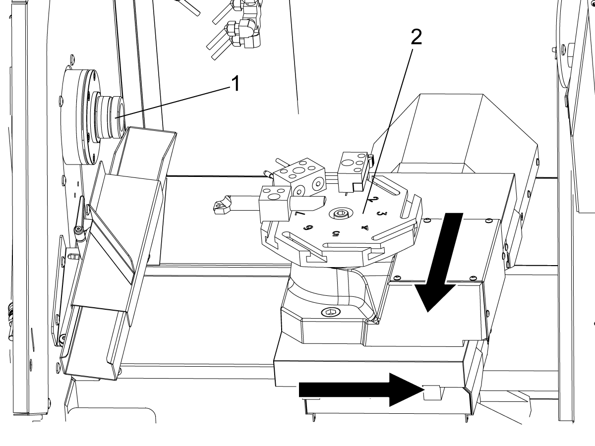
Power-Up X/Z-Axis Home Movement and Possible Crash Areas:

  • Spindle[1]
  • Cross-slide with tool post, riser block, or tool changer[2] 

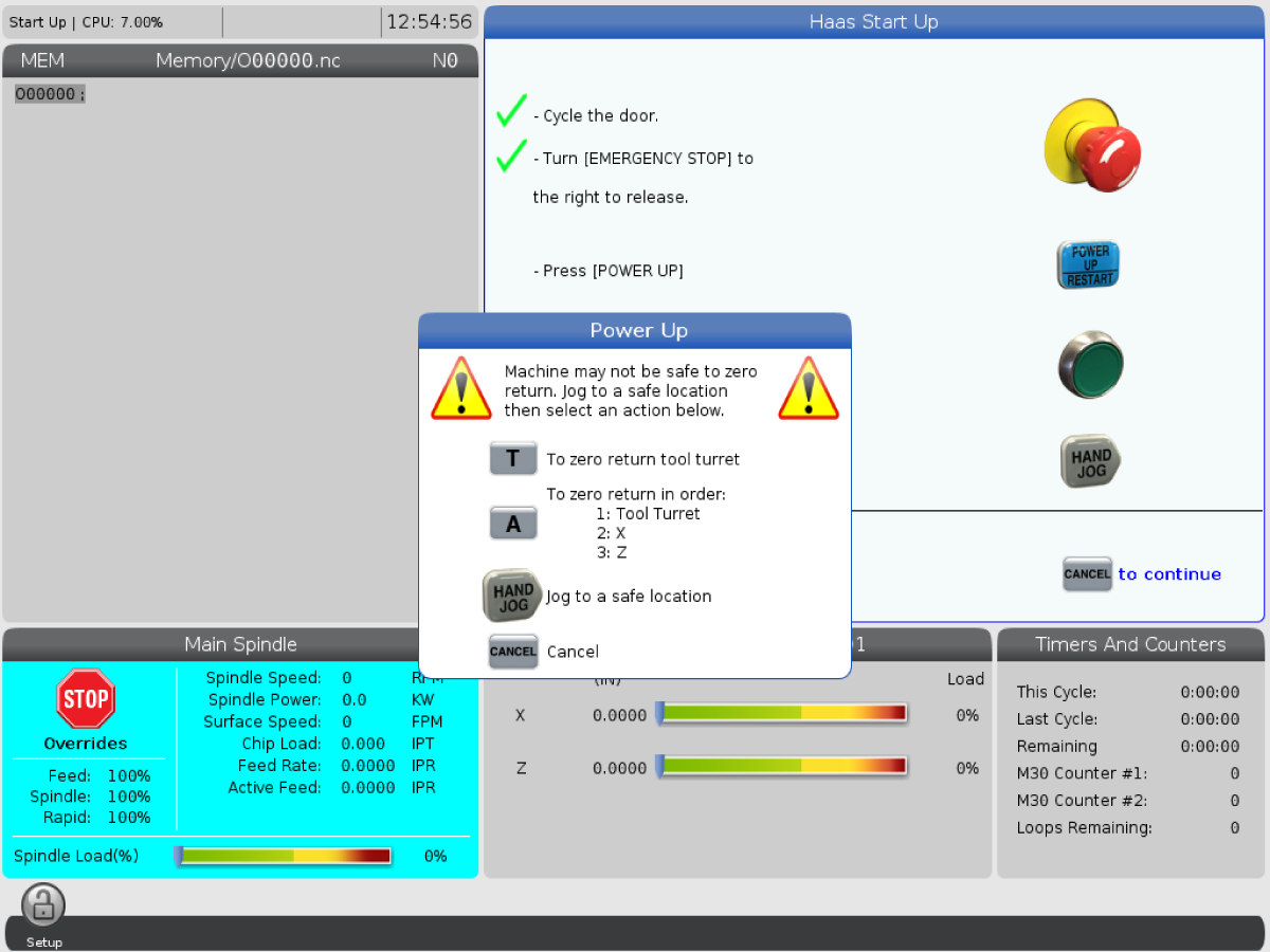
1. Press and hold [POWER ON] until you see the Haas logo on the screen. After a self-test and boot sequence, the display shows the startup screen. The startup screen gives basic instructions to start the machine. Press [CANCEL] to dismiss the screen. You can also press [F1] to disable it.

2. Turn [EMERGENCY STOP] clockwise to reset it.

3. Press [RESET] to clear the startup alarms. If you cannot clear an alarm, the machine may need service. Contact your Haas Factory Outlet (HFO) for assistance.

4. Close the doors.

Warning: Before you do the next step, remember that automatic motion begins immediately when you press [POWER UP/RESTART]. Make sure the motion path is clear. Stay away from the spindle, tool changer.

5. Press [POWER UP]. The axes move slowly until the machine finds the home switch for each axis. This establishes the machine home position. The control is now in OPERATION:MEM mode. 

6.2 CL - Workholding

CL - Workholding

Installing a Collect:

1. Open the large operator door.

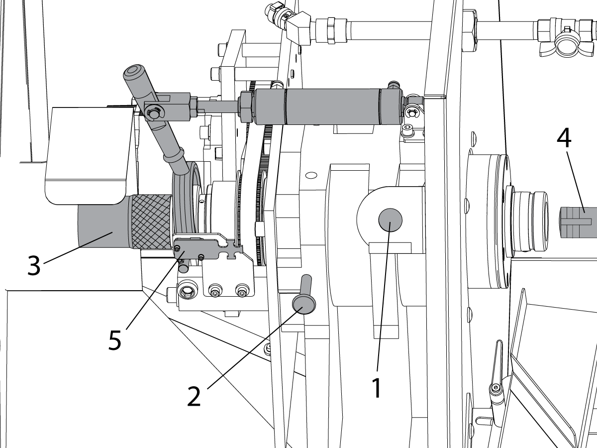
2. Press the CHUCK button[1] to unclamp the collet. The message “UNCLAMPED” appears on the control screen.

3. Push on the spindle lock pin[2] and turn the spindle by hand until the pin engages and the spindle can not turn.

4. Turn the knurled knob[3] at the end of the drawbar assembly clockwise until you can insert the collet[4] into the spindle nose. The spindle contains a collet anti-rotation pin to align the collet for installation. Turn the collet in the spindle head until you feel the anti-rotation pin engage with the pin slot on the collet.

5. Turn the knurled knob clockwise to draw the collet into the spindle. You will feel the draw bar tighten on the collet threads. 

 Note: Make sure the collet is correctly aligned with the anti-rotation pin. An incorrectly aligned collet can damage the spindle and the collet.

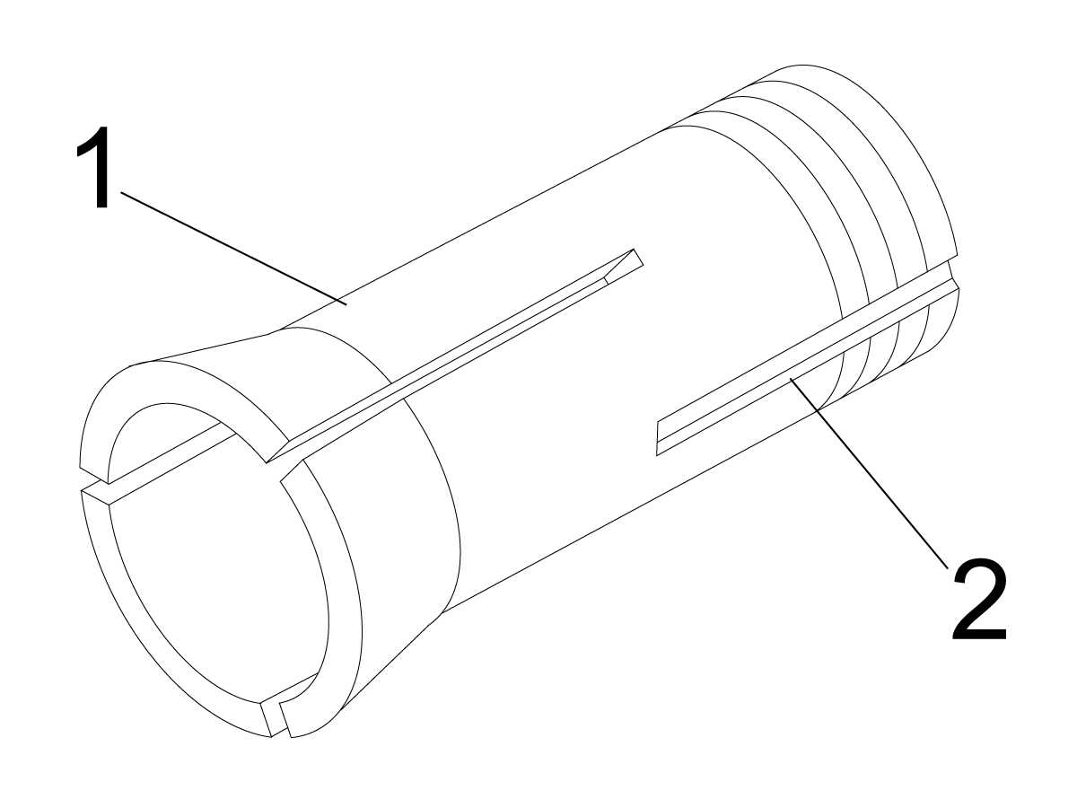
Collet Anti-rotation Pin:

1. Collet
2. Collet anti-rotation pin slot.

Collet Use Tips:

Some collets hold certain materials better than others, so make sure to choose the proper collet for the application (i.e., serrated vs. smooth). Standard collets pull back while they clamp material. If the part outer diameter (OD) varies, pullback (Z-distance) will vary. Because of their design, dead length (exact length) collets position parts more consistently.

Note: Do not try to adjust the length of the draw bar arm air cylinder. Contact Haas Service for adjustment. If roller bearings spin while the spindle turns, contact Haas Service.

Inserting a Workpiece:

1. Put a part into the open collet.

2. Turn the knurled knob clockwise until the part is tight in the collet, then loosen the knob about one half-turn.

3. Press the CHUCK button. Make sure that the part is clamped in the collet.

Warning: If the part is in place, but the collet and the part are not tight, do not operate the spindle.

4. Next, find the correct clamping force for your stock:

  • Press the CHUCK button to unclamp the collet (‘UNCLAMPED’ will be displayed on the screen).
  • Turn the knurled knob slightly; clockwise to tighten, counterclockwise to loosen.
  • Press the CHUCK button to clamp the collet.The part is properly clamped when the draw bar arm hesitates during clamping, then continues to the end of the piston stroke. The mechanism makes a distinct sound when it clamps.

Warning: If the arm does not go to full stroke, the collet has not properly clamped the part. The machine will not start the spindle until the micro switch[5] is tripped when the collet is clamped.

 Warning: If the arm does not hesitate while the part is clamped, the part will not be clamped tightly and it may spin when the tool makes contact. The part may also come out, causing damage or injury.

5. Do a couple of test clamps to make sure the collet is set at the correct tension.

Note: A standard 5C collet has a maximum adjustment range of only around 0.010". Part diameter variation or bar stock variations may therefore cause improper clamping. Good machining practices include regular inspection of bar stock diameter and/or adjustment of the collet.

6. Make sure to disengage the spindle lock pin before you try to operate the spindle.

Warning: Failure to disgengage the spindle lock pin can damage the lock collar on the spindle assembly. This deformation can contact the spindle housing while the spindle rotates. The lock collar cannot be replaced. The entire spindle assembly will need to replaced if the lock collar is damaged enough to contact the spindle house and cause vibration while the spindle rotates.

Removing a Collet:

1. Open the large operator door and press the CHUCK button to unclamp the collet.

2. Push on the pin and turn the spindle by hand until the pin engages and the spindle can not turn.

3. Turn the knurled knob counterclockwise to begin loosening the collet. If there is bar stock in the collet, remove it from the collet as soon as it is loose enough.

4. Keep turning the knurled knob until the collet is loose, then remove the collet from the spindle. Collet Use Tips Some collets hold certain materials better than others, so make sure to choose the proper collet for the application (i.e., serrated vs. smooth). Standard collets pull back while they clamp material. If the part outer diameter (OD) varies, pullback (Z-distance) will vary. Because of their design, dead length (exact length) collets position parts more consistently.

Installing a Chuck:

1. Engage the spindle lock pin while you do this procedure.
2. Attach the chuck to its back plate with the Socket Head Cap Screws (SHCS) supplied in the kit. Torque the SHCS to 25 ft-lbs.

Installing a Chuck:

1. Socket-head cap screw (SCHS)
2. Face plate
3. Chuck.
4. Gently turn the assembly onto the spindle nose until it seats against the spindle shoulder. Tighten the chuck with a strap wrench to approximately 70 ft-lbs.

Chuck Alignment: Follow this procedure to eliminate runout in the chuck.

1. Place a precision test bar in the chuck.
2. Set a dial indicator against the test bar and rotate the chuck.
3. Use the chuck adjustment screws to align the chuck until the dial indicator reads zero.

Chuck Removal:

1. Engage the spindle lock pin.
2. Use a strap wrench to unscrew the chuck. To avoid damaging the chuck, do not pry against the chuck jaws.

6.3 ATT8 Turret Operation

CL - ATT8 Turret Operation

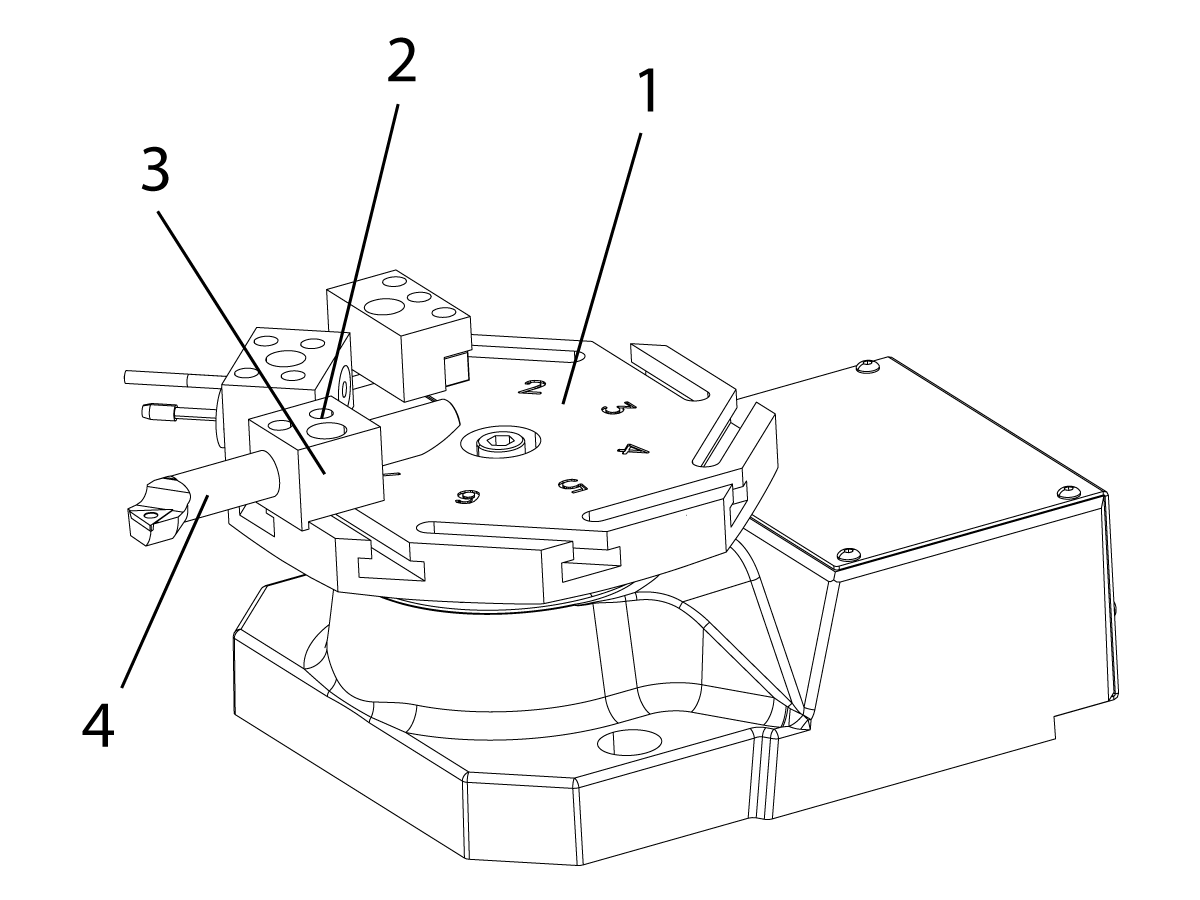
ATT8 Turret Detail:

1. Turret
2. Tool-Retention Screws
3. Tool Holder
4. Tool

Note: The ATT8 has a 1/2 inch turning tool height from the top of the turret.

To set up the ATT8 turret:

  1. Loosen the tool-retention screws[2].
  2. Put the tool[4] into the tool holder[3] and tighten the tool-retention screws[2].


Caution: It is not recommended to use the ATT8 tool changer on a machine with the tailstock option.


Caution: If you use the air gun to remove chips and coolant from the turret, do not blow air into the ring cover at the base of the turret. Compressed air can force chips and coolant into the mechanism. This damages the unit.

CL - ATT8 Turret Operation Test

%
T1;
T2;
T3;
T4;
T5;
T6;
T7;
T8;
T7;
T6;
T5;
T4;
T3;
T2;
M99;
;
;
;
%

Use this program to test the tool changer:

Note: Use T-address codes to operate the tool changer. For example, T303 rotates the tool changer to the number 3 tool position, and uses offset 3. Add the T-address code to the program like the other lines of code. Refer to the Lathe Operator’s manual for more information on the T-codes and tool offsets.

6.4 ATT8 Tool Change Recovery

CL - ATT8 Turret Tool Change Recovery

To recover the tool changer from an incomplete tool change:

1. Press [MDI].
2. Press [TURRET FWD] or [TURRET REV].

Caution: The tool changer moves rapidly when you push [TURRET FWD] or [TURRET REV]. To prevent injury, give the turret sufficient clearance.

6.5 Bar Pusher - Load Bars

Bar Pusher - Load Bars

Note: The bar pusher can only be used with a collet. Do not use a chuck with the pusher option.

To set up the bar pusher:

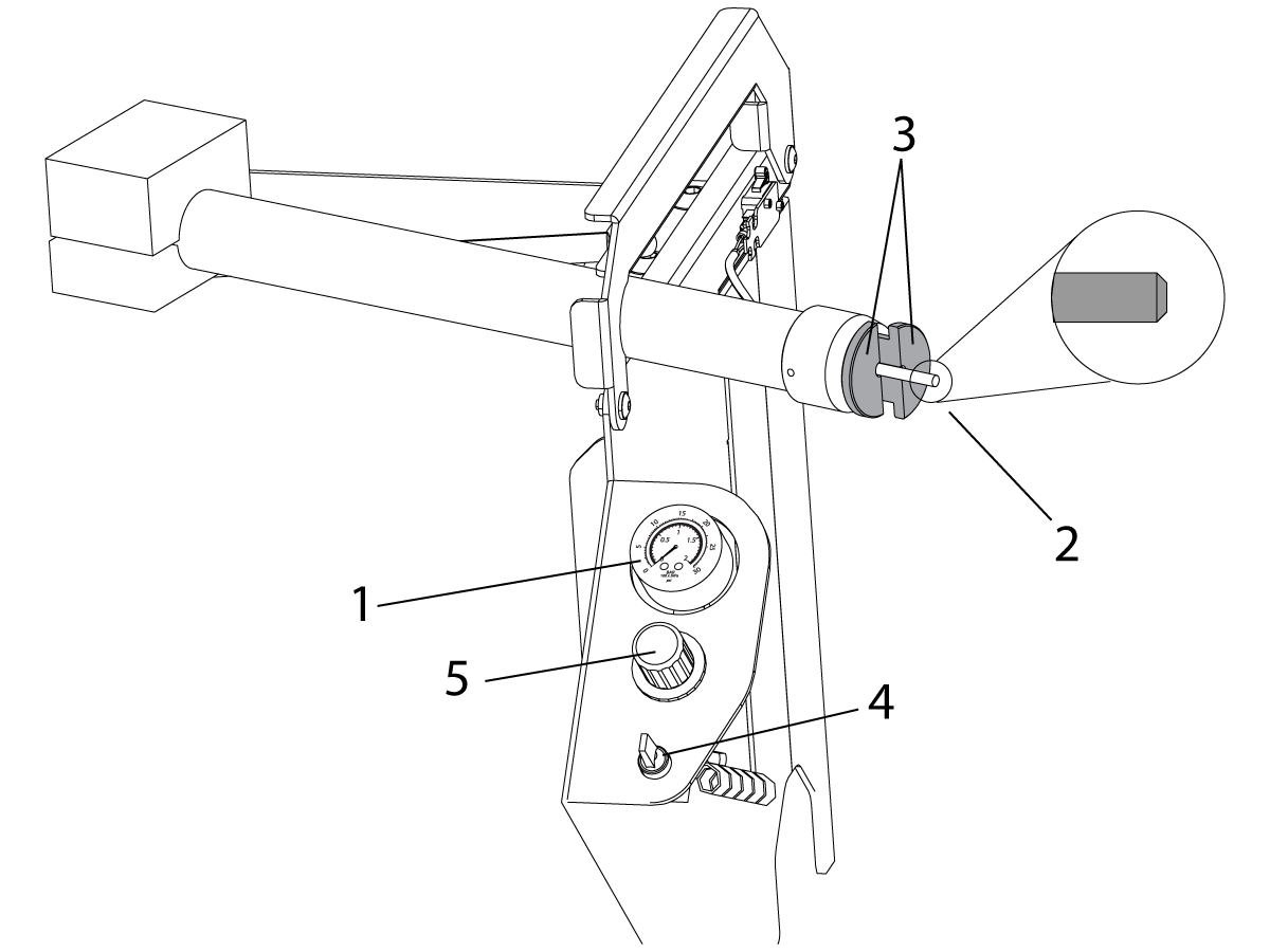
1. Check the bar pusher air pressure gauge[1], it should read 0 PSI/BAR. If not press [RESET] on the control.

2. With the operator door open, rotate the bar pusher tube to the load position.

3. Insert one piece of bar stock into the pusher tube[2] and install a two piece support collar [3] in the end of the pusher tube.

Note: The bar stock should have a slight chamfer on both ends to prevent binding and inconsistent push lengths. For bars over 0.750” add a chamfer to make sure they fit correctly on the cone.

4. Manually feed the bar using the manual feed switch[4]. Adjust the pusher air regulator[5] until the bar pushes out smoothly. Larger bar stock will require more air pressure. Stop feeding the bar when adjusted and push it back into the pusher tube.

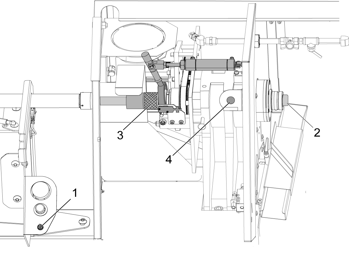
5. Rotate the bar pusher tube back to the run position. Using the manual feed switch[1] manually feed the bar stock into the collet to the position where it will be cut off[2]. Turn the knurled knob clockwise[3] until the part is tight in the collet, then loosen the knob about one half-turn. Press the clamp button to clamp the collet[4]. The part is properly clamped when the draw bar arm hesitates during clampling, then continues to the end of the piston stroke. The mechanism makes a distinct sound when it clamps.

Warning: If the part is in place, but the collet and the part are not tight, do not operate the spindle.

 Warning: If the arm does not go to full stroke, the collet has not properly clamped the part. The machine will not start the spindle until the micro switch is tripped when the collet is clamped.

Warning: If the arm does not hesitate while the part is clamped, the part will not be clamped tightly and it may spin when the tool makes contact. The part may also come out, causing damage or injury.

6.6 Bar Pusher - Setup

Bar Pusher - Setup

Bar Pusher Operation Setup:

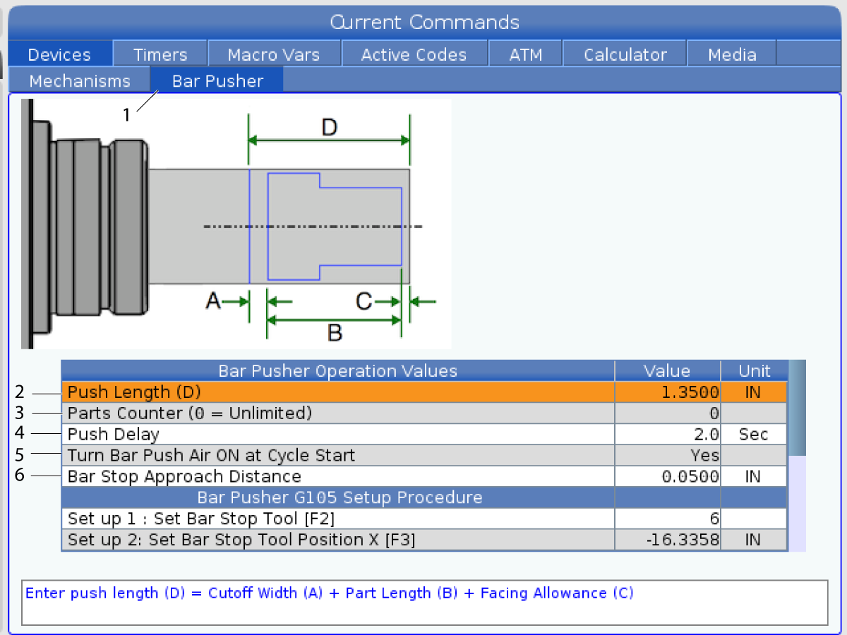
1. Set Setting 336 Bar Feeder Enable to ON. Press the [CURRENT COMMANDS] button. Navigate to the Bar Pusher tab[1].

2. Push Length (D) [2]. Enter the part length plus cut off width and facing allowance.

3. Parts Counter (0 = Unlimited) [3]. Enter the Maximum Number of Parts. Set to 0 to run unlimited number of parts.

4. Push Delay [4]. Enter the time in seconds for the air push delay. This setting controls the length of time the machine waits for the bar pusher to pressurize before advancing the bar.

5. Bar Push Air ON at Cycle Start [5]. Press [RIGHT] arrow to select Yes or No from the drop down menu. This feature when set to YES will keep constant air pressure to the pusher to support the part.

Note: Smaller diameter material should have Bar Push Air On at Cycle Start setting set to Yes to prevent bar whip while running.

6. Bar Stop Approach Distance [6]. This setting is used for positioning the turret at the start and end of the bar feed operation.

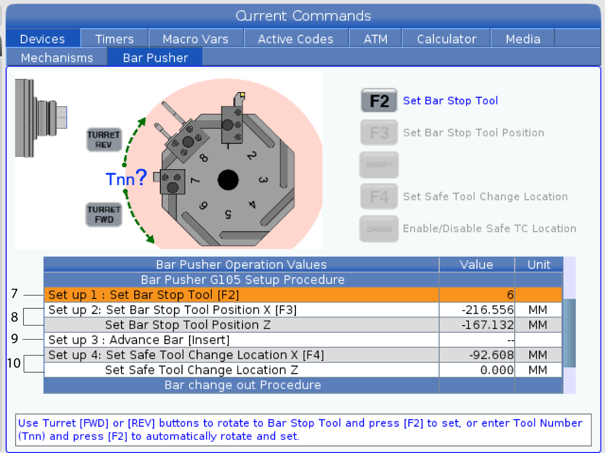
7. Select a tool with a flat edge that you want to use for the bar pusher stop. Handle jog the tool until the X and Z are even with the cutoff position[7].

Set up 1: Set Bar Stop Tool [F2]: This setting sets the bar stop tool. Use the turret [FWD] or [REV] buttons to rotate to the Bar Stop Tool and press [F2] to set, or enter the tool number (Tnn) and press [F2] to automatically rotate and set.

8. Set up 2: Set Bar Stop tool Position X [F3]: Set Bar Stop Tool Position Z [8]. Press the [HANDLE SCROLL] button to handle jog the turret. Handle Jog the Bar Stop tool to the Z part-off position and press [F3] to save the X and Z positions.

9. Set up 3: Advance Bar [Insert] [9]: This setting advances the bar. This setting is used to advance the bar. Press [INSERT] to perform a G105 and advance the bar to the Part Zero (Work Offset) position.

Note: The stock must be manually pushed back to the cut off position before pressing [INSERT] again.

10. Set up 4: Set Safe Tool Change Location X [F4], Set Safe Tool Change Location Z. Handle Jog the turret to a safe tool change location. Press [F4] to save the X and Z positions.

6.7 Bar Pusher - Operation

Bar Pusher - Operation

O00010;
Z-0.95;
N102 X0.4;
;
G00 G53 X-18.6 Z-3.;
(PART-OFF);
T505;
G50 S4000;
S4000 M03;
G00 G54 X0.4 Z0.1;
M08;
G01 Z-0.87 F0.01;
M36;
G04 P1.;
X-0.025 F0.002;
M37;
G00 X0.4 Z0.1;
;
G00 G53 X-18.6 Z-3.;
M01;
;
;
G105 (BARFEED);
;
M99;

To Operate the Bar Pusher:

1. After the bar pusher has been set up, the push is activated by a G105 command in a program. Above is an example of a bar push after a part cutoff at then end of a program.

2. At the end of the pusher stroke the piston will push out the collars and activate the EOB pressure switch.

6.8 Bar Pusher - Change Bars

Bar Pusher - Change Bars

Procedure to Change Out a Bar:

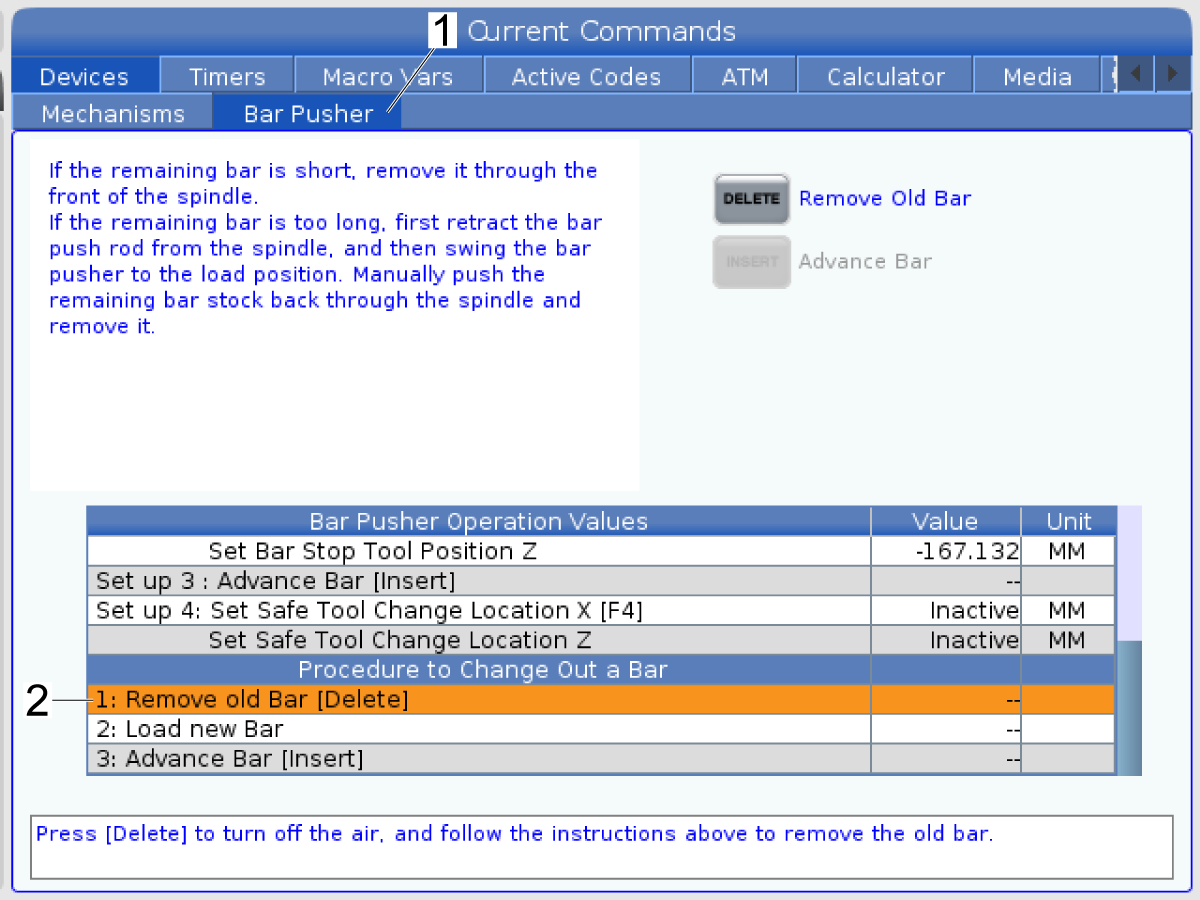
Press the [CURRENT COMMANDS] button. Navigate to the Bar Pusher tab. Press [PAGE DOWN] until you find Procedure to Change Out a Bar settings.

2. 1: Remove old Bar [Delete]. Use this setting to remove a bar. Press [DELETE] to turn off the air. Follow the instructions on the screen to remove the old bar.

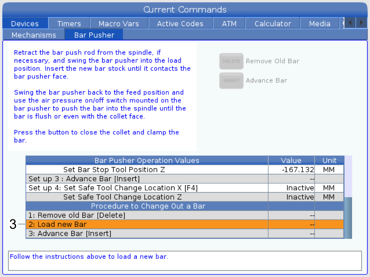
3. 2: Load new Bar [2]. Use this setting to load a new bar. Follow the instructions on the screen to load a new bar.

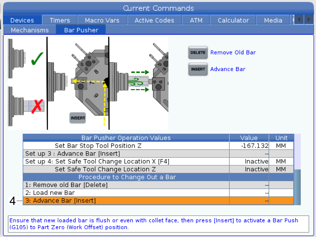
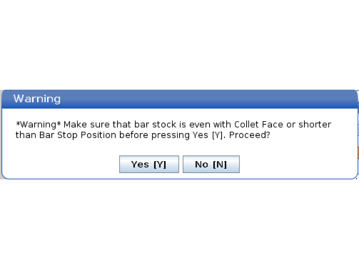
4: Advance Bar [Insert] [3]. This setting is used to advance the bar. Press [INSERT] to perform a G105 and advance the bar to the Part Zero (Work Offset) position. A warning pop up box will appear after you press [INSERT].

Press [Y] to proceed or [N] to cancel.

Note: The stock must be manually pushed back to the cut off position before pressing [INSERT] again.

6.9 CL - Parts Catcher Setup

CL - Parts Catcher Setup

Chucker Lathe Parts Catcher:
[1] Part Chute
[2] Side-to-Side Adjustment Clamp
[3] Parts Tray
To Setup the Parts Catcher:
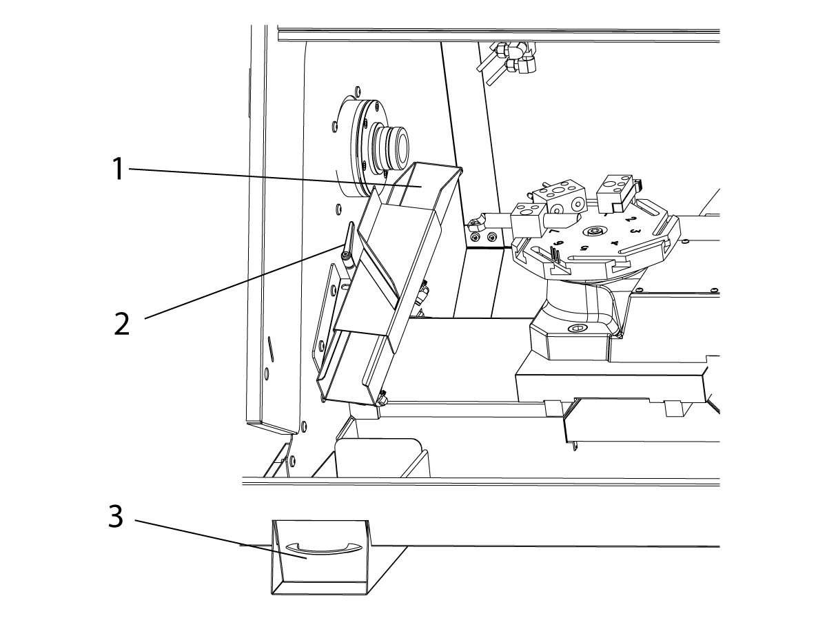
1. Extend the stock out of the collet to the length of the finished part. Clamp the collet.
2. Command an M36 to extend the part chute[1]. Loosen the adjustment clamp[2] and position the part chute as needed to catch the stock.
3. Press [RESET] to retract the parts chute.

6.10 CL - Parts Catcher Operation

Bar Pusher - Operation

O00213;
;
;
G00 G53 X-18.6 Z-3.;
M01;
;
;
N2;
G00 G53 X-18.6 Z-3.;
(PART-OFF);
T505;
G50 S4000;
S4000 M03;
G00 G54 X0.4 Z0.1;
M08;
G01 Z-0.87 F0.01;
M36 9PART CATCHER ON);
G04 P1.;
X-0.025 F0.002;
M37 (PART CATCHER OFF);
G00 X0.4 Z0.1;
;
G00 G53 X-18.6 Z-3.;
M01;
;
;
G105 (BARFEED);
;
M99;

To Operate the Parts Catcher:

1. The parts catcher is activated with an M36 and is deactivated with an M37.

2. With the parts catcher setup, use an M36 while the part is being cut off. This is an example program using the parts catcher during a part off.

3. The cutoff parts will fall into the part tray. Pull out the tray and empty the parts as needed.

Feedback

Recently Viewed Items

You Have No Recently Viewed Items Yet

Feedback
Haas Logo

Haas Delivered Price

This price includes shipping cost, export and import duties, insurance, and any other expenses incurred during shipping to a location in France agreed with you as a buyer. No other mandatory costs can be added to the delivery of a Haas CNC Product.

KEEP UP WITH THE LATEST HAAS TIPS AND TECHNOLOGY...

Sign up now!   

HAAS TOOLING ACCEPTS THE FOLLOWING:

  • Service & Support
  • Owners
  • Request Service
  • Operator Manuals
  • Haas Parts
  • Rotary Repair Request
  • Pre-Install Guides
  • Shopping Tools
  • Build & Price a New Haas
  • Available Inventory
  • The Haas Price List
  • CNCA Financing
  • About Haas
  • Accessibility Statement
  • DNSH Statement
  • Export Compliance
  • Careers
  • Certifications & Safety
  • Contact Us
  • History
  • Terms & Conditions
  • Haas Tooling Terms & Conditions
  • Privacy
  • Warranty
  • Haas Community
  • Haas Certification Program
  • Haas Motorsports
  • Gene Haas Foundation
  • Haas Technical Education Community
  • Events
  • Join the Conversation
  • Facebook
  • X
  • Flickr
  • YouTube
  • LinkedIn
  • Instagram
  • TikTok
© 2026 Haas Automation, Inc – CNC Machine Tools

This site is protected by reCAPTCHA and the Google Privacy Policy and Terms of Service apply.

2800 Sturgis Rd., Oxnard, CA 93030
Toll Free: (888) 817-4446 / Fax: 805-278-8554