-
機械
-
立型マシニングセンター
立型マシニングセンター
-
多軸制御ソリューション
多軸制御ソリューション
-
旋盤
旋盤
-
横型マシニングセンター
横型マシニングセンター
-
ロータリーとインデクサ
ロータリーとインデクサ
-
オートメーション システム
オートメーション システム
-
デスクトップ機械
デスクトップ機械
-
工場機器
工場機器
-
製造機械
製造機械
ショッピングツール -
立型マシニングセンター
-
オプション
-
/2026-04-VOP-SquareComponent.jpg/_jcr_content/renditions/cq5dam.thumbnail.319.319.png) バリューオプションパッケージ
バリューオプションパッケージ
バリューオプションパッケージ
バリューオプションパッケージ -
 スピンドル
スピンドル
スピンドル
スピンドル -
 ツールチェンジャー
ツールチェンジャー
ツールチェンジャー -
 第4軸 | 第5軸
第4軸 | 第5軸
第4軸 | 第5軸 -
 タレットと回転工具
タレットと回転工具
タレットと回転工具 -
 検査
検査
検査
検査 -
 チップおよびクーラントの管理
チップおよびクーラントの管理
チップおよびクーラントの管理 -
 Haas制御
Haas制御
Haas制御 -
 生産オプション
生産オプション
生産オプション -
 ツーリングおよび固定具
ツーリングおよび固定具
ツーリングおよび固定具 -
 保持具
保持具
保持具
保持具 -
 5軸ソリューション
5軸ソリューション
5軸ソリューション -
 自動化
自動化
自動化
自動化
ショッピングツール -
-
Why Haas
Haasの特徴を見る
-
サービス
Haas Service へようこそ
- ビデオ
-
ショッピングツール
-


.png)
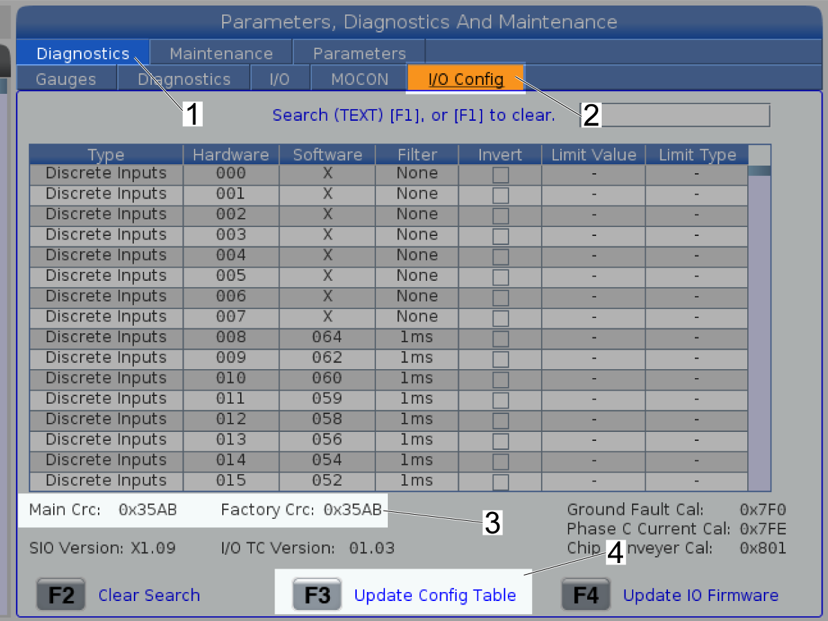
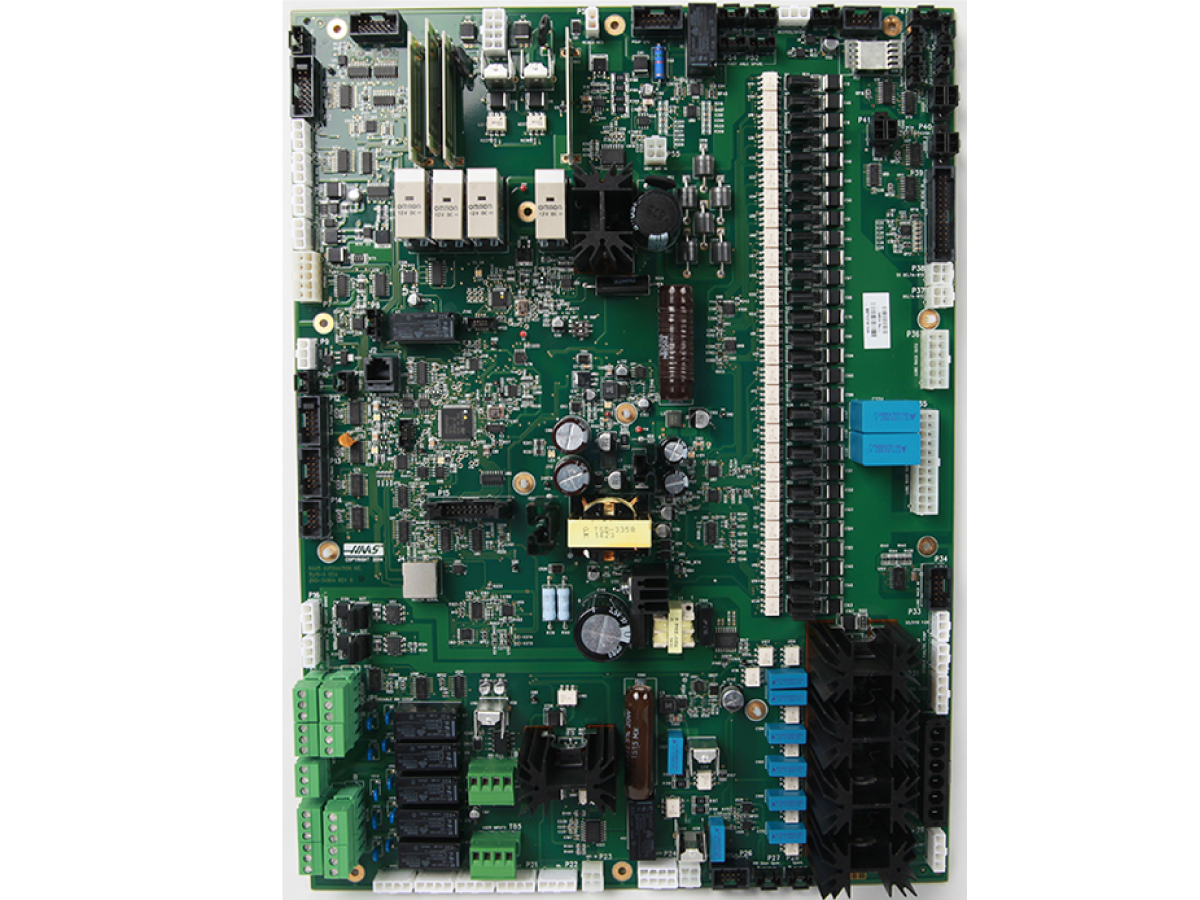
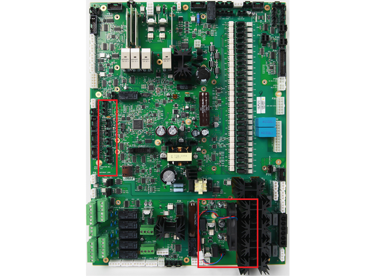
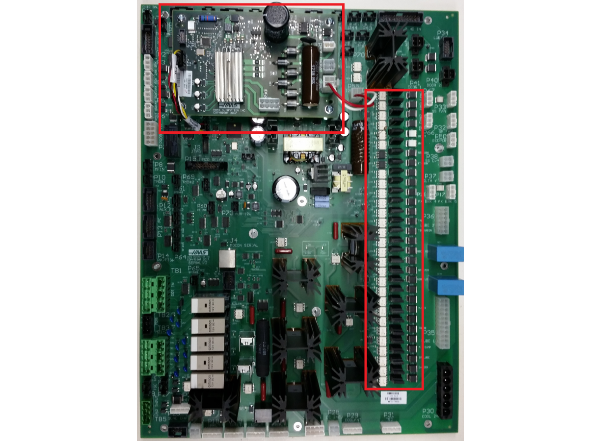
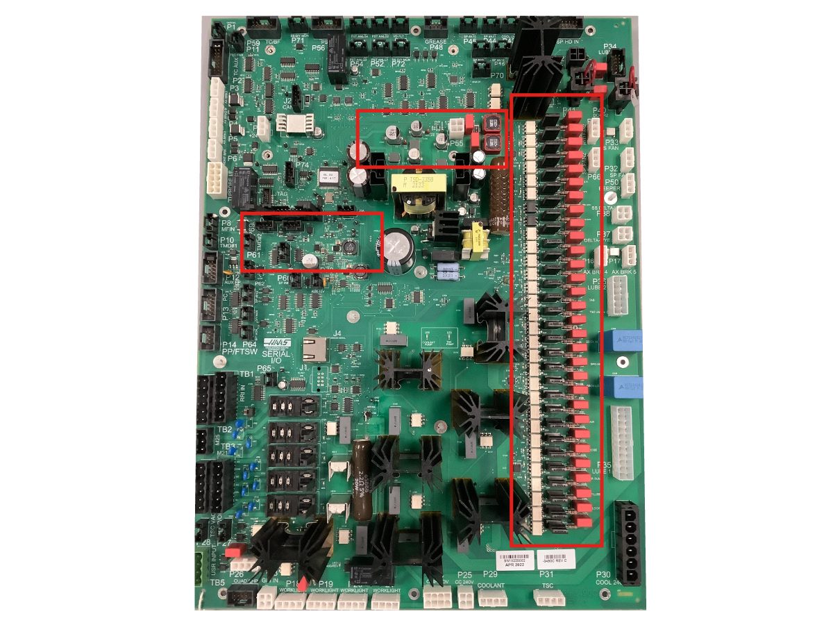
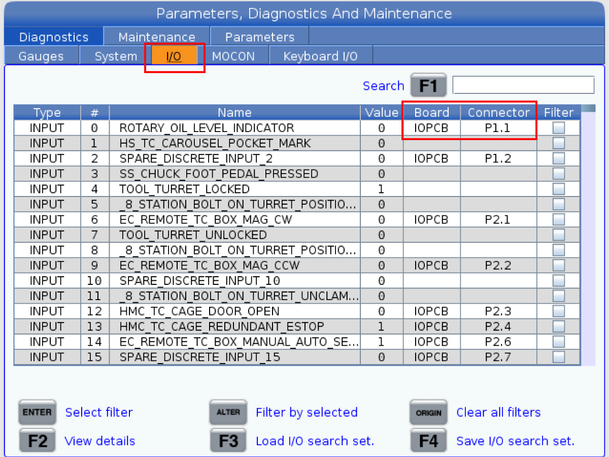
---troubleshooting-guide/io-pcb-le7-location.png)