×

Search Results

Web Pages

Images

    • <
    • 1
    • >
  • machines
    • Haas Vertical Mills
      Vertical Mills
      • Vertical Mills
      • VF Series
      • Universal Machines
      • VR Series
      • Pallet-Changing VMCs
      • Mini Mills
      • Mold Machines
      • Drill/ Tap/ Mill Series
      • Toolroom Mills
      • Compact Mills
      • Gantry Series
      • Vertical Mill/Turn
      • Extra-Large VMC
      • Double-Column Mills
      • Desktop Mill
      • Mill Auto Parts Loader
    • Product Image
      Multi-Axis Solutions
      • Multi-Axis Solutions
      • Y-Axis Lathes
      • 5-Axis Mills
    • Haas Lathes
      Lathes
      • Lathes
      • ST Series
      • Dual-Spindle
      • Toolroom Lathes
      • Chucker Lathe
      • Haas Bar Feeder V2
      • Lathe Auto Parts Loader
    • Haas Horizontal Mills
      Horizontal Mills
      • Horizontal Mills
      • 50-Taper
      • 40-Taper
    • Haas Rotaries & Indexers
      Rotaries & Indexers
      • Rotaries & Indexers
      • Rotary Tables
      • Indexers
      • 5-Axis Rotaries
      • Extra-Large Rotaries
    • Product Image
      Automation Systems
      • Automation Systems
      • Robot Systems
      • Automatic Parts Loaders
      • Pallet-Pool Systems
      • Haas Bar Feeder
      • Models
    • QUICK LINKS Special Series  Special Series 
      HAAS CAREERS HAAS CAREERS BUILD & PRICE BUILD & PRICE PRICE LIST PRICE LIST WHAT’S NEW WHAT’S NEW YOUR FIRST CNC YOUR FIRST CNC HAAS SIX PACK HAAS SIX PACK
      SHOPPING TOOLS
      • Build & Price a Haas
      • Price List
      • Available Inventory
      • CNCA Financing
      WANT TO TALK TO SOMEONE?

      A Haas Factory Outlet (HFO) can answer your questions, and walk you through your best options.

      CONTACT YOUR DISTRIBUTOR >
  • Options
    • Product Image
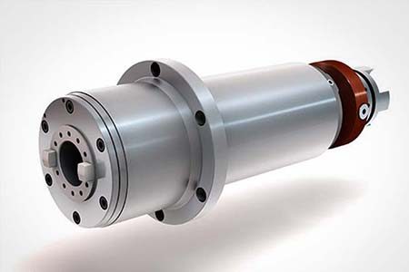
      Spindles
      • Spindles
    • Product Image
      Tool Changers
      • Tool Changers
    • Product Image
      4th- | 5th-Axis
      • 4th- | 5th-Axis
    • Product Image
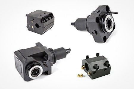
      Turrets & Live Tooling
      • Turrets & Live Tooling
    • Product Image
      Probing
      • Probing
    • Haas Chip & Coolant Management
      Chip & Coolant Management
      • Chip & Coolant Management
    • The Haas Control
      The Haas Control
      • The Haas Control
    • Product Image
      Product Options
      • Product Options
    • Product Image
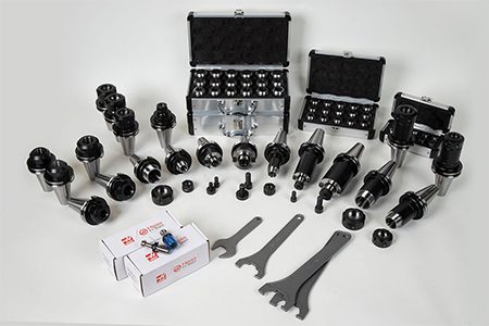
      Tooling & Fixturing
      • Tooling & Fixturing
    • Product Image
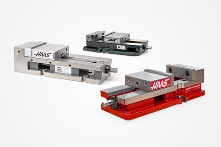
      Workholding
      • Workholding
    • Product Image
      5-Axis Solutions
      • 5-Axis Solutions
      • 5 Easy Steps to 5-Axis
    • Product Image
      Automation
      • Automation
    • QUICK LINKS Special Series  Special Series 
      HAAS CAREERS HAAS CAREERS BUILD & PRICE BUILD & PRICE PRICE LIST PRICE LIST WHAT’S NEW WHAT’S NEW YOUR FIRST CNC YOUR FIRST CNC HAAS SIX PACK HAAS SIX PACK
      SHOPPING TOOLS
      • Build & Price a Haas
      • Price List
      • Available Inventory
      • CNCA Financing
      WANT TO TALK TO SOMEONE?

      A Haas Factory Outlet (HFO) can answer your questions, and walk you through your best options.

      CONTACT YOUR DISTRIBUTOR >
  • Why Haas
      Discover the Haas Difference
      Why Haas MyHaas Education Community Industry 4.0 Haas Certification Customer Testimonials
  • Service
      Welcome to Haas Service
      SERVICE HOME Operator’s Manuals How-To Procedures Troubleshooting Guides Preventive Maintenance Haas Parts Haas Tooling Videos
  • Videos
  • Haas Tooling
      Haas Tooling Mill Toolholding Mill Workholding Milling Lathe Tooling Lathe Toolholding Lathe Workholding ER Collets & Chucks Holemaking Threading Tool Management Tooling Accessories Package Kits Measuring & Inspection Apparel & Accessories
      HAAS TOOLING QUICK LINKS
      NEW PRODUCTS NEW PRODUCTS
      MOST POPULAR MOST POPULAR
      OPEN TERMS OPEN TERMS
      FINANCING FINANCING
      FAQs FAQs
      KITS CREATED FOR YOU KITS CREATED FOR YOU
  • Haas Service Parts
      Haas Service Parts Automatic Pallet Changer Automatic Tool Changer Chip Management Coolant Counterbalance Electrical Cabinet Enclosure Field Install Options Hydraulics Lubrication Maintenance Pendant Probing Rotary Spindle Tailstock
  • Contact Us

My Cart
MyHaas Welcome,
!
Haas Tooling Guest Order History MyHaas/HaasConnect Sign In Register Haas Tooling My Account Order History Return History MyHaas/HaasConnect Sign Out Welcome, My Machines Latest Activity My Quotes My Account My Users Sign Out
Find A Dealer
  1. Select Language
    1. English
    2. Deutsch
    3. Español
    4. Français
    5. Italiano
    6. Português
    7. Český
    8. Dansk
    9. Nederlands
    10. Magyar
    11. Polski
    12. Svenska
    13. Русский
    14. Türkçe
    15. 中文
    16. Suomi
    17. Norsk
    18. الإنجليزية
    19. български
    20. Hrvatski
    21. Ελληνικά
    22. Română
    23. Slovenský
    24. Slovenščina
    25. 한국어
    26. 日本語
Search
×

Search Results

Web Pages

Images

    • <
    • 1
    • >

I/O PCB - Troubleshooting Guide - NGC

Service Home I/O PCB - Troubleshooting Guide - NGC

I/O PCB - Troubleshooting Guide - NGC

Jump to Section Back to Top
Recently Updated Last updated: 08/30/2021

I/O PCB - Troubleshooting Guide - NGC


Introduction

Download and fillout the NGC I/O PCB Inspection Report Checklist below before replacing any parts.

NGC I/O PCB Inspection Report Checklist
34-348xA
  • Release Date: 09/2014
  • Main Firmware Version: 01.XX

    Note: Firmware version cannot be upgraded to version 02.XX

  • TC Firmware Version: 01.XX

    Note: Firmware version cannot be upgraded to version 02.XX

34-348xC
  • Release Date: 05/2016
  • Main Firmware Version: 02.XX

    Note: Firmware version cannot be upgraded to version 03.XX

  • TC Firmware Version: 01.XX

    Note: Firmware version cannot be upgraded to version 02.XX

  • Backwards compatible with 34-348xA
  • Y/D Feedback Support
  • TSC/HPC 1K Fan Support
34-349x
  • Release Date: 05/2018
  • Main Firmware Version: 03.XX - 04.XX
    Note: See the I/O Firmware Compatibility chart for recommended firmware version.

  • TC Firmware Version: 02.XX 
    Note: The 02.xx version will show if the I/O PCB has a TC PCB installed.  If the TC PCB is not installed the firmware version will show "No TC".

  • Backwards compatible with 34-348xA, 34-348xC
  • Redundant Axis Brake Support
  • Optional TC PCB
  • Outputs have LED's lights

I/O, Autodoor Firmware Compatibility

 Important:  Damage can occur to the I/O PCB if incompatible firmware is installed.  Look at the part number that is located on the I/O PCB  and make sure that you load the correct firmware version.  Refer to the I/O PCB Firmware compatibility table below.

I/O, CAN PCB Firmware Compatibility Table
NGC I/O PCB  SIO (Main) Version I/O TC Version CAN Auto Door / E-Vise PCB Version CAN Spindle Head / Lube Panel PCB Version
34-348xA 01.xx 01.xx N/A N/A
34-348xC 02.xx 01.08 or higher N/A N/A
34-349x 04.09 or higher 02.06 or higher  01.28 or higher 1.10 or higher

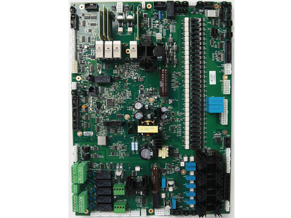
I/O PCB Connector and Pin Information

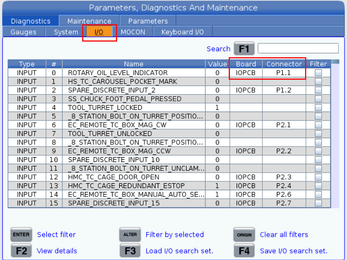
As of NGC software version 100.17.000.1016 or higher connector and pin number has been added to the I/O diagnostic tab.  The PCB board name has also been added.  This will help when troubleshooting a machine and trying to figure out which connector and pin number to probe.

The format for the connector and pin numbers are Pmm.nn where mm is the connector number and nn is the pin number.  For example, connector P56 and pin 5 would be represented as P56.5.  In some cases, a given signal may be present on more than one pin or connector.  In this case, they will be separated by a comma.

In addition to providing information on I/O signals, the table now includes rows for things like power and ground pins.

You can also use the search function to search for specific connector numbers.  For example you can search for connector P3 then press the [F1],  this will display all the input and output fuctions of connector P3.

Electrical Safety

 Caution: When you do maintenance or repair on CNC machines and their components, you must always follow basic safety precautions. This decreases the risk of injury and mechanical damage.

  • Set the main circuit breaker to the [OFF] position.

 Danger: Before beginning any work inside the control cabinet the High Voltage indicator light on the 320V Power Supply / Vector Drive must have been off for at least 5 minutes.

Some service procedures can be dangerous or life-threatening. DO NOT attempt a procedure that you do not fully understand. If you have any doubts about doing a procedure contact your Haas Factory Outlet (HFO) and schedule a service visit.

Symptom Table

Symptom / Alarm Possible Cause Corrective Action
Alarm 9100 NON RESETTABLE SOFTWARE ERROR at Power On, or Alarm 9915 IO BOARD CONFIGURATION MISMATCH. Main CRC and Factory CRC do not match due to the I/O PCB being swapped out.
  1. Press [POWER OFF].
  2. Put the USB memory device into the control.

    Note: The USB memory device must contain your Haas Control Key and the correct configuration files.

  3. Press [POWER ON].
  4. Press [DIAGNOSTIC].
  5. Go to I/O Config [2] in the Diagnostics tab [1].
  6. Press [F3] to Update Config Table [4].
  7. Press [RESET] to continue. If the alarm does not clear, cycle the machine power.

The Main CRC and the Factory CRC[3] are now the same.

Alarm 9933 SOFTWARE VERSION MISMATCH and 9100
 NON RESETTABLE SOFTWARE ERROR
The firmware update failed, or I/O firmware is corrupted. Reload the I/O PCB main firmware refer to Next Generation Control - I/O PCB Main Firmware - Update.
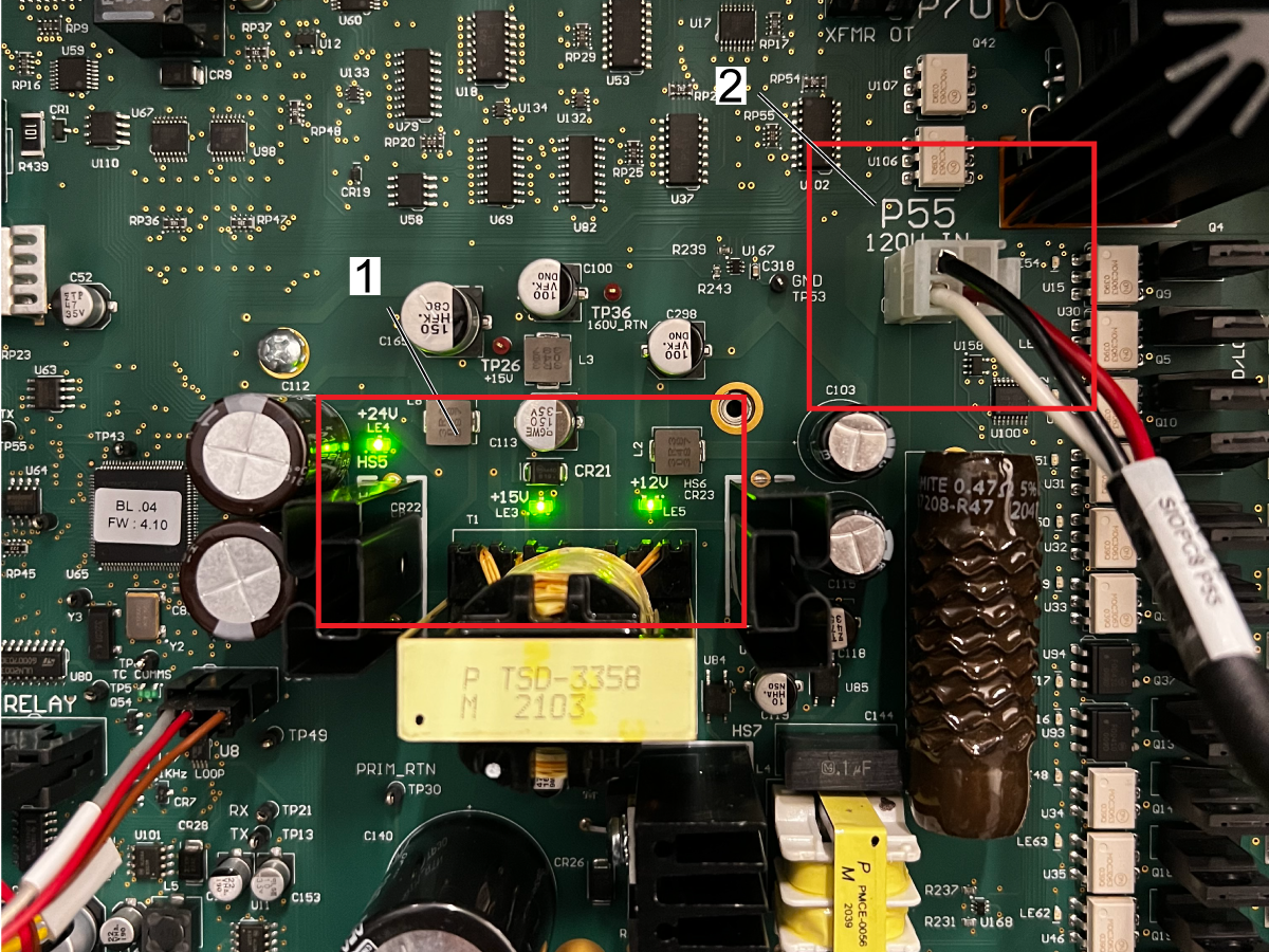
Multiple Alarms or 9924 CONTROL AND IO BOARD COMMUNICATION LOST 9925 CONTROL AND IO BOARD COMMUNICATION DID NOT INITIALIZE and all the input values on the diagnostic page show XX. The I/O PCB board lost communications with the Maincon PCB.
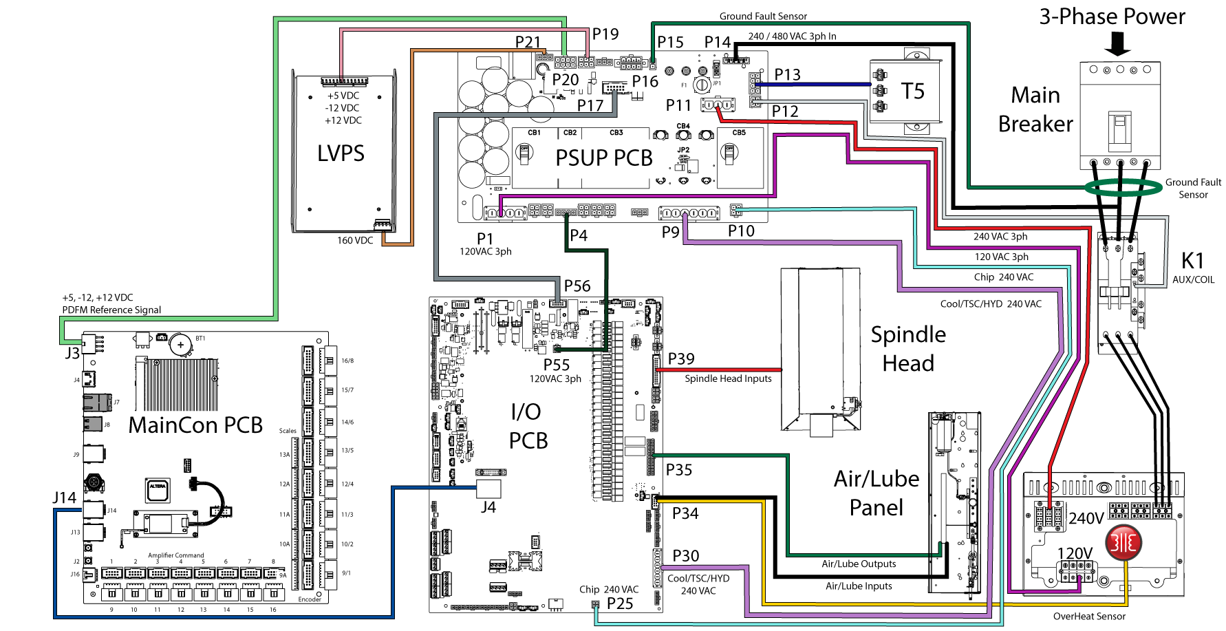
  1. Check the RJ-45cable connection from Maincon PCB (J14) to I/O PCB (J4). To test the cable refer to Network Cable Tester Tool procedure.
  2. Check the 3-Phase power input from PSUP(P4) to I/O PCB (P55).
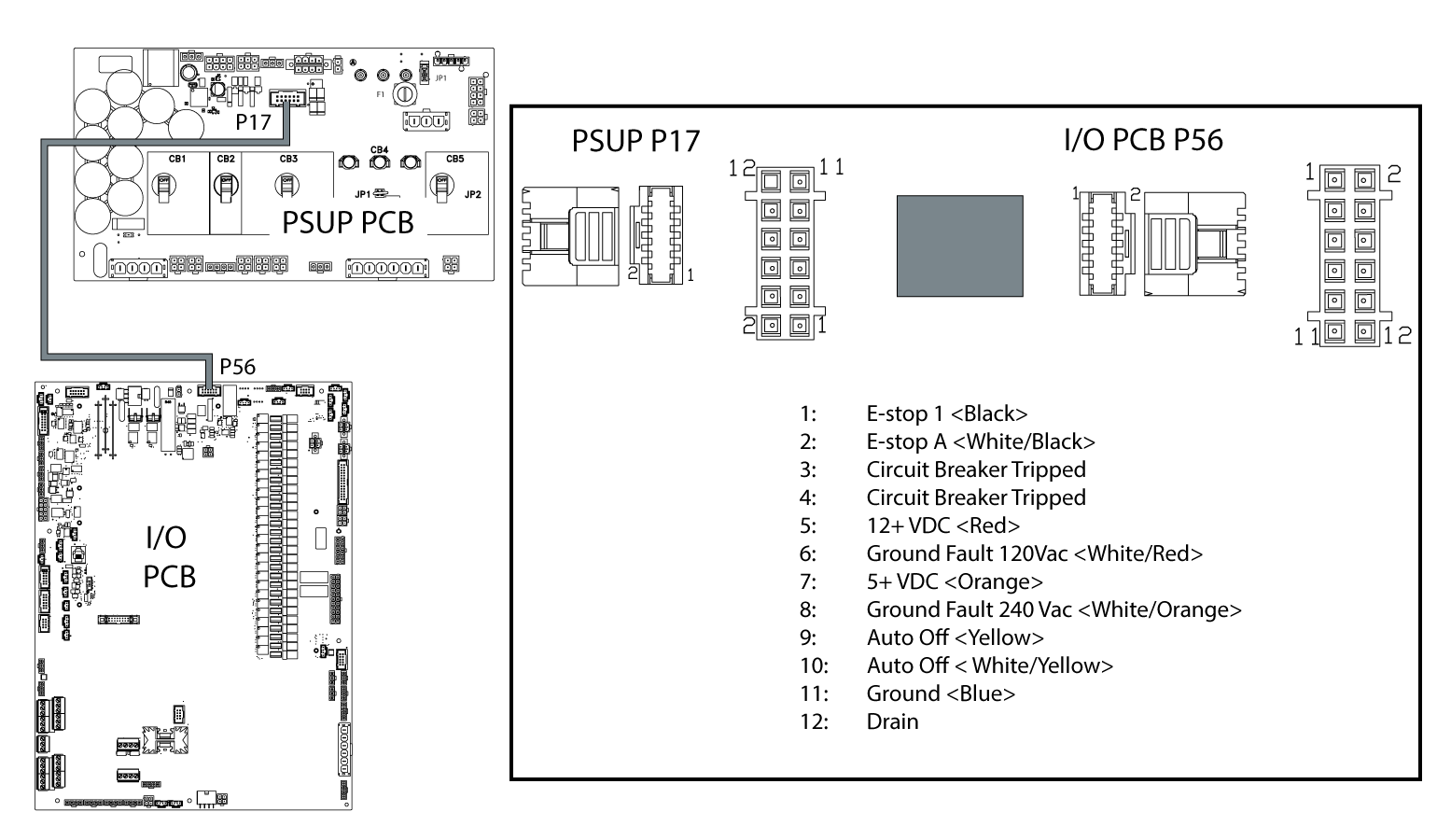
  3. Inspect the cable from PSUP(P17) to I/O PCB (P56), pull on each wire to make sure the pin is correctly locked in the housing.
  4. Make sure the Traffic, TC Comms, Loop, 15 Vdc, 12Vdc, and 24Vdc LEDs are lit. If they are not lit it could be an indication that a phase is missing, trace the 3-phase power to the source.
  5. Inspect the RJ-45 connector on the Maincon PCB & I/O PCB for bent pins.
Alarm 9924 CONTROL AND IO BOARD COMMUNICATION LOST is generated during a Tool Changer cycle  and Tool Changer motion continues. The I/O PCB firmware is outdated. Update I/O Main and TC firmware version to the latest.  Refer to Next Generation Control - I/O PCB Main Firmware - Update.
Alarm 9101.004  RESETTABLE SOFTWARE ERROR The I/O PCB board lost communications with the Maincon PCB.
  1. Check the RJ-45cable connection from Maincon PCB (J14) to I/O PCB (J4). To test the cable refer to Network Cable Tester Tool procedure.
  2. Check the 3-Phase power input from PSUP(P4) to I/O PCB (P55).
  3. Inspect the cable from PSUP(P17) to I/O PCB (P56), pull on each wire to make sure the pin is correctly locked in the housing.
  4. Make sure the Traffic, TC Comms, Loop, 15 Vdc, 12Vdc, and 24Vdc LEDs are lit. If they are not lit it could be an indication that a phase is missing, trace the 3-phase power to the source.
  5. Inspect the RJ-45 connector on the Maincon PCB & I/O PCB for bent pins.
Alarm 2095 TRANSFORMER OVERHEAT.
The machine detected a open circuit from the thermal switch at the transformer. Refer to: Next Generation Control - Power On/Off Circuit, Main Transformer - Troubleshooting Guide.
Intermitten Alarm 115 CAROUSEL POSITION FAULT.
There is a component failure on the I/O PCB. Inspect the tool changer circuit components on the I/O PCB, see section below.
Alarm 858 ATC CAROUSEL MOTOR ELECTRICAL FAULT
There is a problem with one of the tool changer relays. Swap the I/O PCB tool changer relays.
Spindle load pegs to 200%

There is a problem with the 120 VAC outputs circuit components (solenoids, Wye-Delta, Oil Pump etc.)

Inspect the wiring, pins, and connectors for this circuit.  Inspect the I/O board for faults. Replace the I/O if necessary
Machine generates multiple Alarm 20014.1 SIO TOOL CHANGER PCB IS NOT PRESENT and 20014.0 SIO TOOL CHANGER PCB PRESENT after the I/O TC PCB is installed.
The I/O or TC PCB firmware is outdated.   Update I/O Main and TC firmware version to the latest.  Refer to Next Generation Control - I/O PCB Main Firmware - Update.
Machine with an auxiliary estop generates an estop alarm after the closing of machine doors. The doors closing have shaken the estop and caused a momentarily disconnect and caused an estop of the machine. A debounce capacitor will need to be added to the I/O PCB. Refer to the E-Stop - Debounce procedure.
Main I/O Firmware fails to load.  TC PCB is causing the failure. Remove the TC PCB from the Main I/O PCB.  Then try the Firmware upgrade again.  

Serial I/O PCB Alarms

Depending on the machine software version, I/O PCB main firmware version you will get a different alarm, see table below:

Alarm# / Title

Software 100.17.000.2021 and lower

I/O PCB Main Firmware 02.04 and lower

Alarm# / Title

Software 100.17.000.2030 and higher

I/O PCB (34-348xC) Main Firmware 02.05 and higher

Alarm Troubleshooting

  9830-IOPCB MEMORY DATA LOCKED Attempts were made to download an I/O configuration file while configuration memory was locked.
850-INTERNAL I/O ERROR 9800-INTERNAL I/O ERROR- SHIFT CHAIN An internal I/O circuit board error has been sensed in it's shift chain. - Press the [RESET] button. Power off, and inspect the circuit components on the I/O PCB, see section below.
9801-INTERNAL I/O ERROR-TC COMMUNICATION

An internal I/O circuit board error has been sensed where the main and tool changer microcontrollers could not communicate. - Press the [RESET] button.

Inspect the tool changer relays, make sure the relay sockets are solder into the PCB board.

Do not replace the I/O PCB.

For IO PCB (34-348xA):

·         Upgrade the I/O PCB Tool Changer firmware to the latest 01.xx version.

For IO PCB (34-348xC):

·         Update the I/O PCB Main firmware to the latest 02.xx version.

·         Update the I/O PCB Tool Changer firmware to the latest 01.xx version.

For IO PCB (34-349x):

·         Update the I/O PCB Main firmware to the latest 03.xx version.

Refer to Next Generation Control - I/O PCB Main Firmware - Update procedure.

9900-IOPCB COMMUNICATION LOST 9802-SIO MCU COMMUNICATION LOSS Communication has been lost to the I/O PCB. Check that the I/O PCB has power by looking for the 12/24V green leds. Look for a tripped circuit breaker. If the board has power, then
1. Check the RJ-45 cable connection from Maincon PCB (J14) to I/O PCB (J4). To test the cable refer to Network Cable Tester Tool procedure.
2. Check the 3-Phase power input from PSUP (P4) to I/O PCB (P55).
3. Inspect the RJ-45 connector on the Maincon PCB & I/O PCB for bent pins.
Upgrade the software to 100.17.000.2045 or higher. If you get this alarm with version 100.17.000.2045 or higher download an error report and e-mail to Haas service.
  9831-I/O # ERROR The main processor has command an output that is not configured in the I/O configuration file.
  9832-SIO COMMUNICATION ERROR The I/O PCB has received partial or invalid communication from the main processor.
  9833-PCB OVER TEMPERATURE The I/O PCB is reporting a temperature that exceeds limits (65 degrees C)
  9834-12V FAULT The 12V supply on the I/O PCB is outside of its limits of 10 to 14V.
175-GROUND FAULT DETECTED 9803-120VAC GROUND FAULT A 120 VAC ground fault condition was detected by the I/O PCB.  The ground fault signal gets generated by the PSUP PCB.  The ground fault signal gets sent to  I/O PCB at  P56 for monitoring. Check all 120V outputs for possible shorts to earth ground. See ground fault troubleshooting section below.
9804-240VAC GROUND FAULT A 240 VAC ground fault condition was detected by the I/O PCB.  The ground fault signal gets generated by the PSUP PCB.  The ground fault signal gets sent to I/O PCB at  P56 for monitoring. Check all 240 V outputs for possible shorts to earth ground. This includes short circuits in any amplifier or vector drive ouput as well as any 240V pumps or chip conveyor. See ground fault troubleshooting section below.
9903-120 VAC SHORT CIRCUIT 9805-120VAC PHASE C SHORT CIRCUIT A short circuit was detected in the 120V outputs from the iopcb. Check all 120V outputs for possible shorts to earth ground. See ground fault troubleshooting section below.
  9835-120VAC PHASE C OVER CURRENT A partial short circuit was detected in the 120V outputs from the iopcb. Check all 120V outputs for possible shorts to earth ground. See ground fault troubleshooting section below.
  9836-120VAC PHASE C NO CURRENT An output was turned on but no change in current was detected. Check for broken wires/cables.
  9837-CALIBRATION ERROR I/O PCB Calibration error. Either calibration did not occur during power up. Or the new calibration values don't match the previous values.
  9838-TSC FAN FAILURE The fan for the TSC heat sink stopped; could cause TSC over heating later on.
  9820-TSC HEAT SINK OVER TEMP The TSC Heat sink temperature is over the limit of 85°C. Check for a damaged fan.
9904-PCOOL MALFUNCTION 9806-PCOOL SHORT CIRCUIT The programmable coolant circuit has detected a short circuit (>2.5A) and has shut down. Press the [RESET] button to clear alarms. If necessary, cycle power on the machine. Check for a shorted cable.
9807-PCOOL GROUND FAULT The programmable coolant circuit has detected a ground fault condition and has shut down. Press the [RESET] button to clear alarms. If necessary, cycle power on the machine. Check for a shorted cable to earth ground.
9808-PCOOL OVERHEAT The programmable coolant circuit has overheated and shut down. Give time for it to cool, then press the [RESET] button to clear alarms. Check for obstructions to pcool movement.
  9839-PCOOL STALLED A high current (2.5A> I >1A) was detected in the programmable coolant circuit. Check for obstructions to pcool movement. Check for binding in the pcool unit.
  9840-PCOOL OVERLOAD The programmable coolant circuit has detected an overload condition. Check for binding in the pcool unit.
  9841-PCOOL MOTOR DISCONNECTED The programmable coolant circuit was commanded on but no current was detected. Check to see if the pcool will turn when commanded. Check for broken wires.   If the machine is equipped with 34-3090B I/O PCB make sure the Main I/O firmware has version 3.18 or higher. Refer to Next Generation Control - I/O PCB Main Firmware - Update procedure.
9905-IOPCB TOOL CHANGER FAULT 9809-TOOL CHANGER BUS SHORT CIRCUIT The I/O PCB experienced an internal short circuit. Replace the 4 tool changer relays. If problem persists, then replace the iocpb.
9810-INTERNAL I/O ERROR-TC TRANSISTOR FAILURE The I/O PCB tool changer (or bar feeder) transistor appears to be damaged. Replace the I/O PCB.
9811-TOOL CHANGER CABLE SHORT CIRCUIT One of the tool changer outputs has detected a short circuit. Check all tool changer motor outputs for possible short circuits.
9812-TOOL CHANGER GROUND FAULT A ground fault condition was detected by the I/O PCB tool changer. Check all tool changer motor outputs for possible short circuits to earth ground.
9813-TOOL CHANGER REGEN SHORTED The I/O PCB experienced a short circuit on the tool changer regen circuit. Check for a short circuit on it's external regen resistor at P57.
9814-CAROUSEL BRAKE RESISTOR OVER TEMPERATURE TBD
9815-ARM BRAKE RESISTOR OVER TEMPERATURE TBD
9816-REGEN OVERLOAD TBD
9817-MULTIPLE MOTOR COMMANDS TBD
9818-TOOL CHANGER OVERLOAD TBD
  9842-OVER VOLTAGE TBD
  9822 - IOPCB VERTICAL BRAKE FAILURE NGC machines equipped with I/O PCB P/N: 34-3490A/B and a servo brake motor may generate alarm 9822 IOPCB Brake.  Upgrade the Main I/O PCB firmware to 3.06 or higher.  Refer to I/O PCB Firmware - Update - NGC procedure.
880 - UNDER VOLTAGE ON 160V DC BUS 9843-TC UNDER VOLTAGE

The system detected an undervoltage condition from the TC circuit or the TC PCB.  Check the 115 VAC input to the TC PCB, check for shorts on the tool changer motors.

  1. Phase missing on the 120VAC power from the PSUP
  2. Low voltage level in the 120VAC power from the PSUP
  3. Open diode (s)  in the 120Vac bridge rectifier circuit either in the I/O PCB (34-348x A, 34-348x C  PCBs) or the TC PCB 34-5502 used on 34-349X I/O PCBs
  4. Faulty TC PCB 34-5502 PCB
  5. Faulty I/O PCB
  9844-REGEN OPEN TBD
  9845-CONFIGURATION CONFLICT TBD
  9846-MOTOR STALLED TBD
  9847-MOTOR DISCONNECTED The control software and the I/O firmware are not compatible, or the I/O firmware is outdated. 
9906-CHIP CONVEYOR MALFUNCTION 9819-CHIP CONVEYOR SHORT CIRCUIT TBD
  9848-CHIP CONVEYOR MOTOR DISCONNECTED TBD

Ground Fault Circuit Monitor

On the NGC control there is a ground fault circuit monitor. This circuit monitors the 115V and 230V for a ground fault condition.

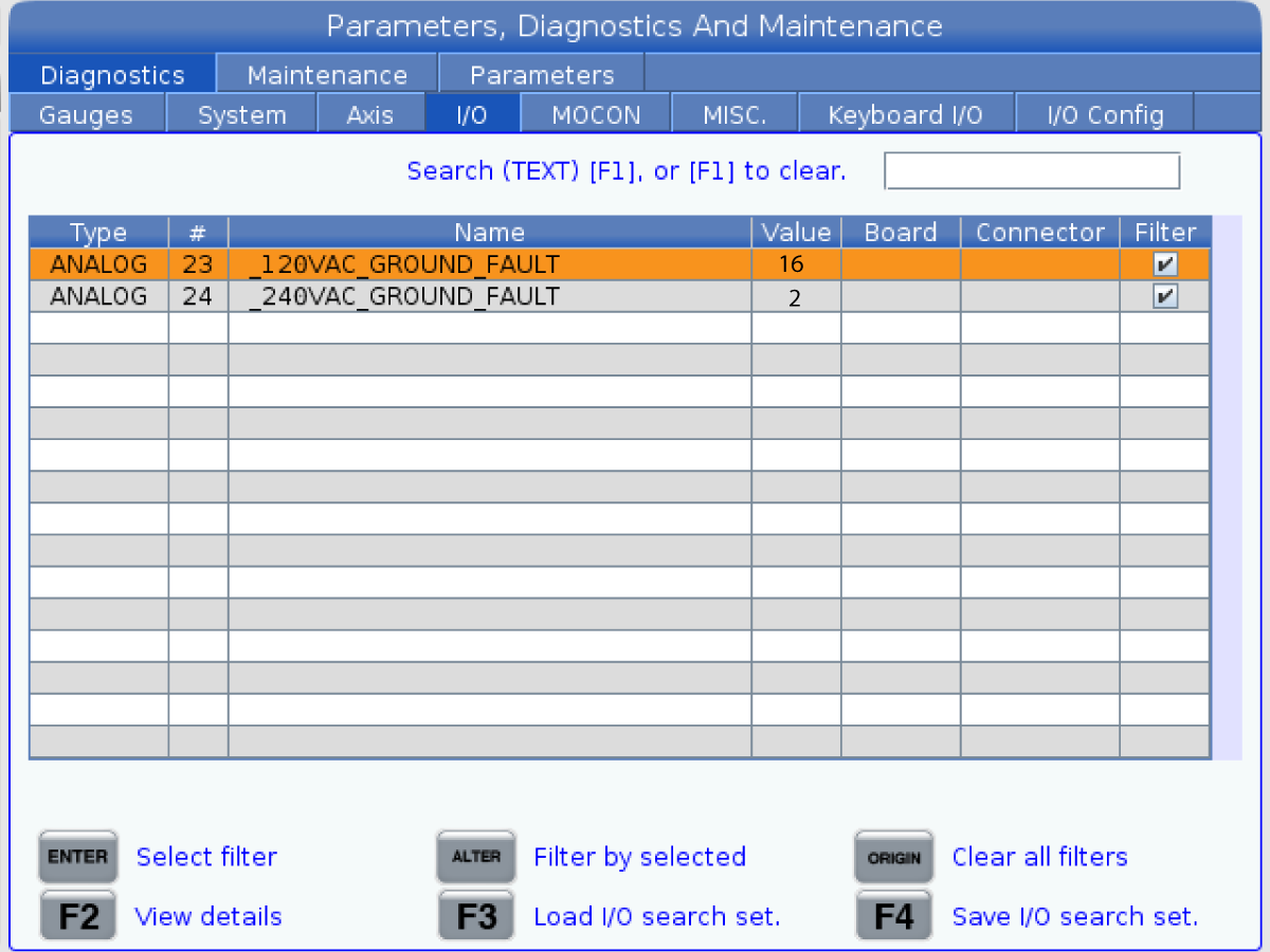
  1. For 175 GROUND FAULT alarm. Determine if the alarm is caused by a 115 or 230 VAC component.
  2. Press the [DIAGNOSTIC] button, cursor to the I/O tab.
  3. Type in: "Ground", then press [F1].
  4. Look at the _120VAC/_240VAC_GROUND FAULT analog value. The circuit with the highest value is the one that reported the ground fault.
  5. Test the components that operate in that voltage range, for a short-circuit (see the table below).
  6. The ground fault analog value will drop when the component with the short circuit is disconnected from the machine control.

Components to Check when a Ground Fault Alarm Occurs

 Note: *These devices can be disconnected from the I/O PCB without an alarm being generated.

Machine Components I/O PCB Location Operating Voltage
4th and 5th Axis Brake Solenoids* P16 - P17 120 VAC
Worklights* P18 - P21 120 VAC
High Intensity Lights* P22 120 VAC
GFI P23 120 VAC
Door Interlocks* P40, P41, P42 120 VAC
Lube Panel Solenoids P35, P36 120 VAC
Y/D Contactor Coil P37, P38 120 VAC
DC Tool Change Motors* P58 160 VDC, generated from the 120 VAC
Spindle Motor Fan / Oil Pump P32 120 VAC
Sub Spindle Fan / Hydraulic Pump Fan P33 120 VAC
TSC/HPC Pump* P31 240 VAC
Coolant Pump* P29 240 VAC
Chip Auger / Conveyor* P24, Quad PCB 240 VAC
Axis Motors   240 VAC
Spindle Motor   240 VAC
Hydraulic Pump Motor   240 VAC

PCB Component Inspection

Intermittent alarms or symptoms can be caused by component failure. Below is a list of possible failures:

  1. Missing solder on all or some components pins
  2. Poor solder
  3. Solder bridges
  4. Wrong component installation (orientation)
  5. Missing components

     Note: Some PCB's have unused circuits and are missing components intentionally, look for broken off components.

  6. Broken components
  7. Broken pins on IC's
  8. Bent pins on the connectors

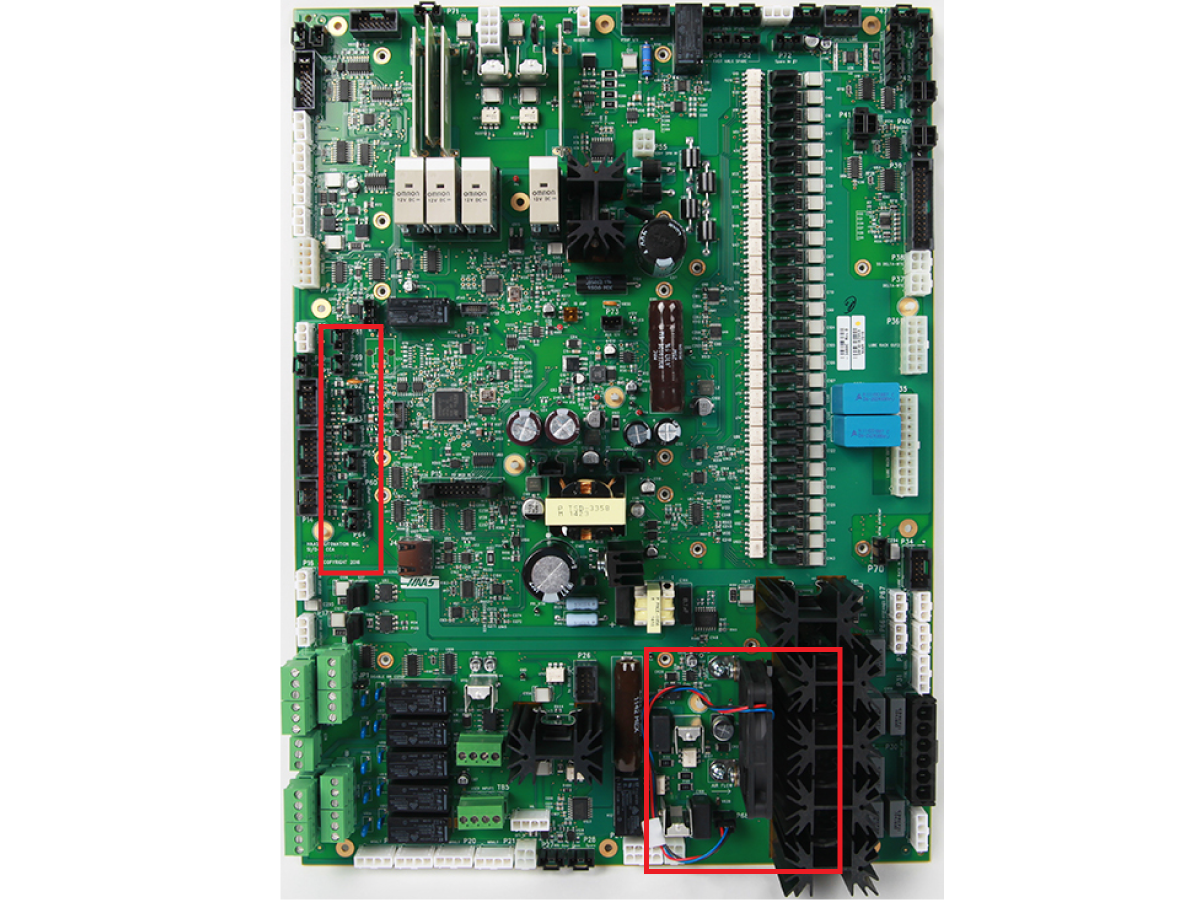
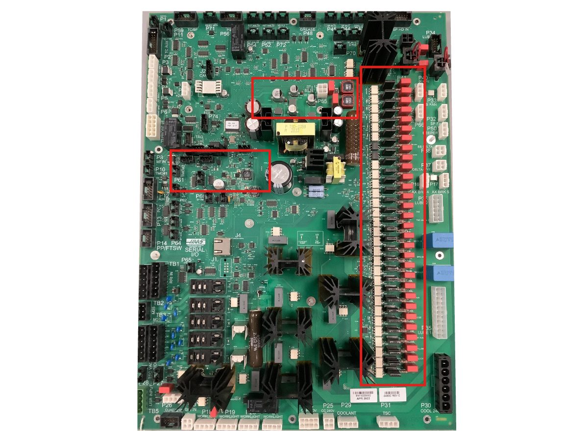
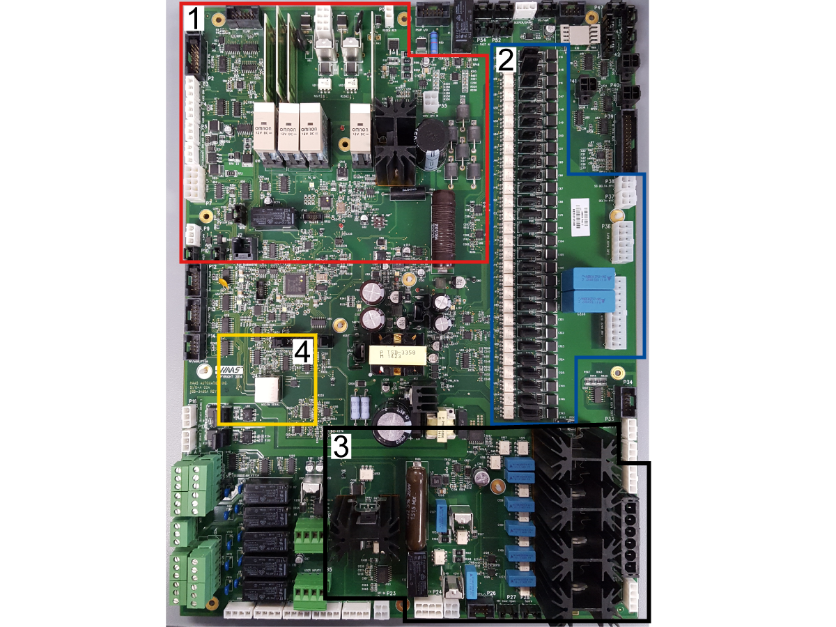
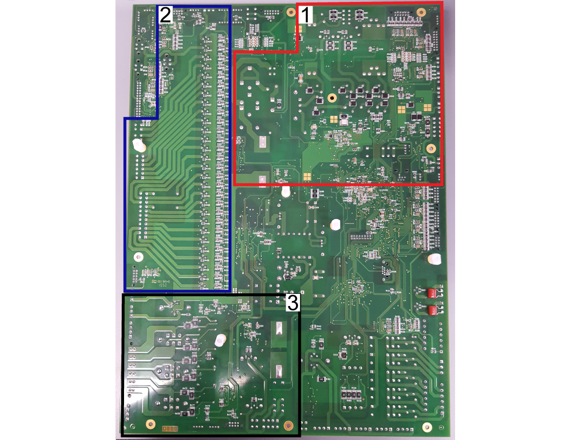
Use a magnifying glass to inspect the circuit components on the front and back of the I/O PCB. Below are the circuit component zones to inspect:

  1. 24 VDC, 160 VDC circuit components (DC motor tool changers, axis brake, probe).
  2. 120 VAC outputs circuit components (solenoids, Wye-Delta, Oil Pump etc.)
  3. 240 VAC outputs circuit components (Coolant, TSC, Auger).
  4. Check the RJ45 connector for loose housing and bent pins.

 Important: If you find a damaged component, replace the I/O PCB, inspect the new I/O PCB circuit components before installing.

Electrical Diagrams

I/O PCB Interconnect Diagram

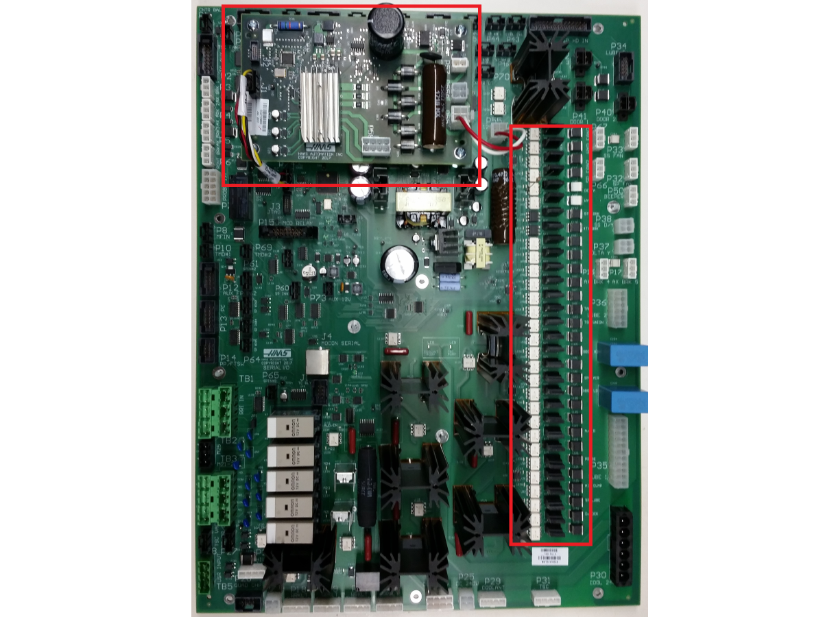
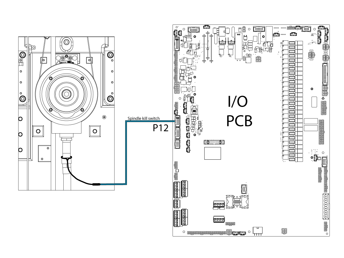
I/O PCB (P39) to Mill - Spindle Head Inputs Detail Diagram

I/O PCB (P34, P35) to Mill - Air/Lube Panel Detail Diagram

PSUP (P17) to I/O PCB (P56) Detail Diagram

Related Content

CAN I/O Systems
Robot Integration
DIagnostic Data
FIND DISTRIBUTOR
Feedback
Haas Logo

美元价格不包括关税、报关费用、保险费、增值税及运费。
USD prices DO NOT include customs duty, customs fees, insurance, VAT, or freight.

人民币价格包含关税、报关费用、货运保险和增值税, 但不包括运费。
CNY prices include customs duty, customs fees, insurance, and VAT. DOES NOT include freight.

Haas Delivered Price

This price includes shipping cost, export and import duties, insurance, and any other expenses incurred during shipping to a location in France agreed with you as a buyer. No other mandatory costs can be added to the delivery of a Haas CNC Product.

KEEP UP WITH THE LATEST HAAS TIPS AND TECHNOLOGY...

Sign up now!   

HAAS TOOLING ACCEPTS THE FOLLOWING:

  • Service & Support
  • Owners
  • Request Service
  • Operator Manuals
  • Haas Parts
  • Rotary Repair Request
  • Pre-Install Guides
  • Shopping Tools
  • Build & Price a New Haas
  • Available Inventory
  • The Haas Price List
  • CNCA Financing
  • About Haas
  • Careers
  • Certifications & Safety
  • Contact Us
  • History
  • Terms & Conditions
  • Haas Tooling Terms & Conditions
  • Privacy
  • Warranty
  • Haas Community
  • Haas Certification Program
  • Haas Motorsports
  • Gene Haas Foundation
  • Haas Technical Education Community
  • Events
  • Join the Conversation
  • Facebook
  • Twitter
  • Flickr
  • YouTube
  • LinkedIn
  • Instagram
  • TikTok
© 2022 Haas Automation, Inc – CNC Machine Tools

2800 Sturgis Rd., Oxnard, CA 93030 / Toll Free: 800-331-6746
Phone: 805-278-1800 / Fax: 805-278-2255

Cookie Notice

We use cookies to improve your user experience. Our Cookie Notice describes which cookies we use, why we use them, and how you can find more information about them. Please confirm you consent to us using analytics cookies. If you do not consent, you may still use our website with a reduced user experience.

Manage Settings

Cookie Notice

We use cookies to improve your user experience. Our Cookie Notice describes which cookies we use, why we use them, and how you can find more information about them. Please confirm you consent to us using analytics cookies. If you do not consent, you may still use our website with a reduced user experience.

Functional Cookies

Analytics Cookies