MyHaas Welcome,
!
Haas Tooling Guest Order History MyHaas/HaasConnect Sign In Register Haas Tooling My Account Order History Return History MyHaas/HaasConnect Sign Out Welcome, My Machines Latest Activity My Quotes My Account My Users Sign Out
Find Your Distributor
  1. Select Language
    1. English
    2. Deutsch
    3. Español - España
    4. Español - México
    5. Français
    6. Italiano
    7. Português
    8. Český
    9. Dansk
    10. Nederlands
    11. Magyar
    12. Polski
    13. Svenska
    14. Türkçe
    15. 中文
    16. Suomi
    17. Norsk
    18. الإنجليزية
    19. български
    20. Hrvatski
    21. Ελληνικά
    22. Română
    23. Slovenský
    24. Slovenščina
    25. 한국어
    26. 日本語
    27. Українська
  • machines Main Menu
    • Haas Vertical Mills Vertical Mills
      Vertical Mills
      Vertical Mills View All
      • Vertical Mills
      • VF Series
      • Universal Machines
      • VR Series
      • VP-5 Prismatic
      • Pallet-Changing VMCs
      • Mini Mills
      • Mold Machines
      • High-Speed Drill Centers
      • Drill/Tap/ Mill Series
      • Toolroom Mills
      • Compact Mills
      • Gantry Series
      • SR Sheet Routers
      • Extra-Large VMC
      • Double-Column Mills
      • Control Simulator
      • Mill Automatic Parts Loader
      • VMC/UMC Side-Loading Automatic Parts Loader
      • Compact Automatic Parts Loader
    • Product Image Multi-Axis Solutions
      Multi-Axis Solutions
      Multi-Axis Solutions View All
      • Multi-Axis Solutions
      • Y-Axis Lathes
      • 5-Axis Mills
    • Haas Lathes Lathes
      Lathes
      Lathes View All
      • Lathes
      • ST Series
      • Dual-Spindle
      • Box Way Series
      • Toolroom Lathes
      • Chucker Lathe
      • Haas Bar Feeder V2
      • Lathe Automatic Parts Loader
    • Haas Horizontal Mills Horizontal Mills
      Horizontal Mills
      Horizontal Mills View All
      • Horizontal Mills
      • 50-Taper
      • 40-Taper
    • Haas Rotaries & Indexers Rotaries & Indexers
      Rotaries & Indexers
      Rotaries & Indexers View All
      • Rotaries & Indexers
      • Rotary Tables
      • Indexers
      • 5-Axis Rotaries
      • Extra-Large Rotaries
    • Special Series
      Special Series
      Special Series View All
      • Special Series
      • EU_Series_Redirect
    • Product Image Automation Systems
      Automation Systems
      Automation Systems View All
      • Automation Systems
      • Mill Automation
      • Lathe Automation
      • Automation Models
    • Haas Drill Centers Desktop Machines
      Desktop Machines
      Desktop Machines View All
      • Desktop Machines
      • Desktop Mill
      • Desktop Lathe
    • Haas Shop Equipment Shop Equipment
      Shop Equipment
      Shop Equipment View All
      • Shop Equipment
      • Bandsaw
      • Knee Mill
      • Surface Grinder, 2550
      • Surface Grinder, 3063
      • Laser Cutting Machine
    • QUICK LINKS Special Series  Special Series 
      EU SERIES EU SERIES BUILD & PRICE | PRICE LIST BUILD & PRICE | PRICE LIST In-Stock Machines In-Stock Machines WHAT’S NEW WHAT’S NEW YOUR FIRST CNC YOUR FIRST CNC
      SHOPPING TOOLS
      • Build & Price a Haas
      • Price List
      • Available Inventory
      • CNCA Financing
      WANT TO TALK TO SOMEONE?

      A Haas Factory Outlet (HFO) can answer your questions, and walk you through your best options.

      CONTACT YOUR DISTRIBUTOR >
  • Options Main Menu
    • Product Image Spindles
      Spindles
      Spindles View All
      • Spindles
    • Product Image Tool Changers
      Tool Changers
      Tool Changers View All
      • Tool Changers
    • Product Image 4th- | 5th-Axis
      4th- | 5th-Axis
      4th- | 5th-Axis View All
      • 4th- | 5th-Axis
    • Product Image Turrets & Live Tooling
      Turrets & Live Tooling
      Turrets & Live Tooling View All
      • Turrets & Live Tooling
    • Product Image Probing
      Probing
      Probing View All
      • Probing
    • Haas Chip & Coolant Management Chip & Coolant Management
      Chip & Coolant Management
      Chip & Coolant Management View All
      • Chip & Coolant Management
    • The Haas Control The Haas Control
      The Haas Control
      The Haas Control View All
      • The Haas Control
    • Product Image Product Options
      Product Options
      Product Options View All
      • Product Options
    • Product Image Tooling & Fixturing
      Tooling & Fixturing
      Tooling & Fixturing View All
      • Tooling & Fixturing
    • Product Image Workholding
      Workholding
      Workholding View All
      • Workholding
    • Product Image 5-Axis Solutions
      5-Axis Solutions
      5-Axis Solutions View All
      • 5-Axis Solutions
      • 5 Easy Steps to 5-Axis
    • QUICK LINKS Special Series  Special Series 
      EU SERIES EU SERIES BUILD & PRICE | PRICE LIST BUILD & PRICE | PRICE LIST In-Stock Machines In-Stock Machines WHAT’S NEW WHAT’S NEW YOUR FIRST CNC YOUR FIRST CNC
      SHOPPING TOOLS
      • Build & Price a Haas
      • Price List
      • Available Inventory
      • CNCA Financing
      WANT TO TALK TO SOMEONE?

      A Haas Factory Outlet (HFO) can answer your questions, and walk you through your best options.

      CONTACT YOUR DISTRIBUTOR >
  • Why Haas Main Menu
      Discover the Haas Difference
    • Why Haas
    • MyHaas
    • Education Community
    • Industry 4.0
    • Haas Certification
    • Customer Testimonials
  • Service Main Menu
      Welcome to Haas Service
      SERVICE HOME Operator’s Manuals How-To Procedures Troubleshooting Guides Preventive Maintenance Haas Parts Haas Tooling Videos
  • Videos Main Menu
  • Main Menu
    • View All
    • View All
      • Fiber Laser
    • View All
    • View All
      • HTEC Curriculum Support
    • View All
      • Haas 10 kg Cobot Package
      • Cobot Kits
    • View All
    • View All
      • 4 - AUTOMATION SYSTEMS
      • Mill Toolholding
      • Carousel-V2
    • View All
    • View All
    • View All
      • VF-4SS
    • View All
    • QUICK LINKS Special Series  Special Series 
      EU SERIES EU SERIES BUILD & PRICE | PRICE LIST BUILD & PRICE | PRICE LIST In-Stock Machines In-Stock Machines WHAT’S NEW WHAT’S NEW YOUR FIRST CNC YOUR FIRST CNC
      SHOPPING TOOLS
      • Build & Price a Haas
      • Price List
      • Available Inventory
      • CNCA Financing
      WANT TO TALK TO SOMEONE?

      A Haas Factory Outlet (HFO) can answer your questions, and walk you through your best options.

      CONTACT YOUR DISTRIBUTOR >
  • Haas Tooling Main Menu
      Automation Accessories Shop Support Mill Toolholding Mill Cutting Tools Boring Systems Mill Workholding Lathe Toolholding Lathe Cutting Tools Lathe Workholding Package Kits ER Collets & Chucks Holemaking Threading Broaching Tombstones & Kits Manual Chucks For Milling Deburring & Abrasives Tool Presetter & Heat Shrinkers Storage & Handling Machine Maintenance Tooling Accessories Apparel & Accessories Measuring & Inspection Winner's Circle Winner's Circle Clearance Today's Hot Deals
    • Haas Tooling
    • Winner's Circle
      Winner's Circle Shop All
      • WINNERS_CIRCLE-1Y
    • Winner's Circle
      Winner's Circle Shop All
      • WC-1Y-EU
    • Today’s Hot Deals
      Today’s Hot Deals Shop All
      • Mill Toolholding
      • Mill Tooling
      • Measuring & Inspection
      • Boring Systems
      • Mill Workholding
      • Shell Mill Kits
      • Lathe Toolholding
      • Lathe Tooling
      • Lathe Workholding
      • ER Collets & Chucks
      • Holemaking
      • Threading
      • Broaching
      • Tool Storage
      • Apparel & Accessories
    • Clearance
      Clearance Shop All
    • Measuring & Inspection
      Measuring & Inspection Shop All
      • Probe Kits & Accessories
      • Edge & Center Finders
      • Comparative Measuring Gauges
      • Height Gauges
      • Calipers
      • Threaded Plug & Ring Gauges
      • Gauge Blocks
      • Pin Gauges
      • Drop Indicators
      • Dial Test Indicators
      • Bore Gauges
      • Indicator Accessories
      • V Blocks
      • Setup Blocks
      • Depth Measuring
      • Micrometers
      • Micrometer Accessories
      • Micrometer Kits
      • Bore Gauge Kits
      • Starter Kits
      • Indicator Kits
      • Caliper Kits
      • Toolholder Check Station
      • Height Setters
      • Coordinate Measuring Machines
    • Automation Accessories
      Automation Accessories Shop All
      • Cobot Kits
      • Cobot Kits
      • Protective Barriers
      • Grippers
      • Robot Cell Accessories
    • Shop Support
      Shop Support Shop All
      • Air Compressors
      • Laser Marking Machines
      • Bandsaw Blades
      • Bandsaw Accessories
      • Surface Grinding Wheels
      • Shop Equipment Accessories
    • Mill Toolholding
      Mill Toolholding Shop All
      • End Mill Holders
      • Shell Mill Holders
      • Shrink Fit Holders
      • ER Collet Chucks
      • Milling Chucks & Collets
      • NC Drilling Chucks
      • Pull Studs / Retention Knobs
      • Rotary Tool Holder & Tool Chuck Kits
      • Hydraulic Milling Chucks & Collets
      • Toolholder Attachments & Wrenches
      • Mill Broaching Holders
    • Mill Tooling
      Mill Tooling Shop All
      • Shell Mill Bodies
      • Milling Inserts
      • End Mills
      • Chamfer Mills & Inserts
      • Indexable End Mill Bodies
      • Ball End Mills
      • Chamfer End Mills
      • Roughing End Mills
      • Indexable Ball End Mills & Inserts
      • Shell Mill Kits
      • Chamfer Mill Kits
      • Indexable End Mill Kits
      • Dovetail Cutters
      • Indexable Dovetail Cutters
      • Engraving End Mills
      • Rotary Burrs / Die Grinding Bits
      • Keyseat Cutters
      • Corner Rounding End Mills
      • Slot Mill Bodies
      • CNC Router Bits For Wood
    • Boring Systems
      Boring Systems Shop All
      • Boring Heads & Cartridges
      • Boring Holders & Extensions
    • Mill Workholding
      Mill Workholding Shop All
      • Fixed-Jaw Vises
      • Self-Centering Vises
      • Adapter Plates
      • Vise Jaws
      • Vise Mounts & Fixtures
      • Vise Kits
      • Vise Parallels
      • Rotary Vise Kits
      • Fixture Clamps & Rails
      • Automated Workholding Kits
      • Tooling Fixture Subplates
      • Toolmakers' Vises
      • Clamp Force Gauges
      • Collet Fixtures
      • Angle Plates
    • Lathe Toolholding
      Lathe Toolholding Shop All
      • TL & CL Static Turning Holders
      • BOT Static Turning Holders
      • BMT Static Turning Holders
      • Live / Driven Turning Holders
      • Turning Holder Reduction Sleeves / Bushings
      • VDI Static Turning Holders
      • Turning Holder Accessories
    • Lathe Tooling
      Lathe Tooling Shop All
      • Cut-Off Tool Blocks & Blades
      • Cut-Off Tooling Kits
      • Turning Inserts
      • Grooving & Cut-Off Tools
      • Internal (ID) Grooving & Threading Tools
      • Threading Inserts
      • Threading Tools
      • Boring Bars / Internal (ID) Turning Tools
      • External (OD) Turning Tools
      • Cermet Turning Inserts
      • CBN Turning Inserts
      • Haas Notch Grooving & Threading Inserts
      • Haas Notch Grooving & Threading Tools
      • Micro Turning Tools
      • Desktop Lathe Tools
    • Lathe Workholding
      Lathe Workholding Shop All
      • Live Centers
      • Spindle Reduction Sleeves / Liners
      • Quick-Change Collets
      • Quick-Change Collet Chucks
      • 5C Collets
      • 5C Collet Sets
      • Lathe Jaw Boring Rings
      • Lathe Jaws
      • Bar Pullers
      • Scroll Chucks
      • Guide Pins
      • Collet Accessories
    • Package Kits
      Package Kits Shop All
      • Chip Clearing Fan Kits
      • Cutting Tool Kits
      • Indexable End Mill Kits
      • Cut-Off Tool Block & Blade Kits
      • Drill & Tap Kits
      • Indexable Drilling Kits
      • Shell Mill Kits
      • Chamfer Mill Kits
      • Rotary Tool Holder & Tool Chuck Kits
      • Lathe Starter Kits
      • Workholding Kits
      • Rotary Vise Kits
      • Vise Kits
      • 3-Jaw Chuck Kits for Mills
      • Tombstone Kits
      • Reduction Sleeve Kits
      • Automated Workholding Kits
      • Measuring & Inspection Kits
      • Starter Kits
      • Bore Gauge Kits
      • Caliper Kits
      • Indicator Kits
      • Micrometer Kits
    • ER Collets & Chucks
      ER Collets & Chucks Shop All
      • ER Straight-Bore Collets
      • ER Sealed Collets
      • ER Tap Collets
      • ER Collet Sets & Accessories
      • ER Collet Chucks
      • Straight Shank ER Collet Chucks
      • Straight Shank Keyless NC Drilling Chucks
    • Holemaking
      Holemaking Shop All
      • Carbide Drills
      • Indexable Drill Bodies
      • Indexable Drill Inserts
      • Modular Drill Bodies
      • Modular Drill Heads
      • Cobalt Drills & Sets
      • Center Drills
      • Reamers
      • Indexable Drilling Kits
      • Spot Drills
      • Spade Drill Bodies
      • Spade Drill Inserts
      • Countersinks
    • Threading
      Threading Shop All
      • Taps
      • Threading Inserts
      • Threading Tools
      • Thread Mills
      • Pipe Taps
      • Drill Tap Kits
    • Broaching
      Broaching Shop All
      • Broaching Tools
      • Broaching Inserts
    • Tombstones
      Tombstones Shop All
      • Tombstones
      • Tombstone Kits
      • Vise Cluster Towers
    • Manual Chucks For Milling
      Manual Chucks For Milling Shop All
      • 3-Jaw Chucks & Mounts for Mills
    • Deburring & Abrasives
      Deburring & Abrasives Shop All
      • Abrasive Pads
      • Deburr Tools
      • Deburr Wheels
      • Abrasive Sheets & Rolls
      • Sharpening / Lapping Stones
    • Tool Presetter & Heat Shrinkers
      Tool Presetter & Heat Shrinkers Shop All
      • Tool Presetting Machines
      • Shrink Fit Machines
    • Tool Storage
      Tool Storage Shop All
      • Tool Carts
      • Tool Tray
      • Tool Bags
    • Machine Maintenance
      Machine Maintenance Shop All
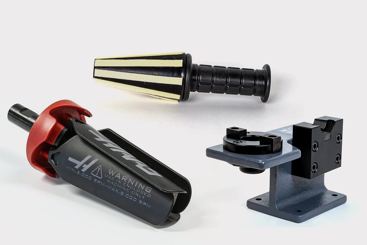
      • Spindle Test Bars
      • Levels
      • Refractometers
      • Machine Additives & Supplies
      • Machine Accessories
      • Machine Maintenance Kits
    • Tooling Accessories
      Tooling Accessories Shop All
      • Spindle & Toolholder Taper Cleaners
      • Haas Shop Lift
      • Toolholder Fixtures
      • CNC Chip Clearing Fans
      • Hammers & Mallets
      • Anti-Fatigue Mats
      • Layout Tools
      • Wrenches
      • Magnetic Tools
      • Torque Screwdrivers
      • Hand Cutting Tools
      • Shop Stools
      • Lifting Magnets
      • Safety Apparel
      • Cutting Tool Sharpeners
    • Apparel & Accessories
      Apparel & Accessories Shop All
      • Accessories
      • Apparel
    • HAAS TOOLING QUICK LINKS
      NEW PRODUCTS NEW PRODUCTS NEW PRODUCTS NEW PRODUCTS
      MOST POPULAR MOST POPULAR
      TOOLING PROMOS TOOLING PROMOS
      FINANCING & OPEN TERMS FINANCING & OPEN TERMS PAY BY INVOICE PAY BY INVOICE
      FAQs FAQs
      KITS CREATED FOR YOU KITS CREATED FOR YOU
  • Haas Service Parts Main Menu
      Automatic Pallet Changer Lathe Turret Tool Changer Chip Management Coolant Counterbalance Electrical Cabinet Enclosure Hydraulics Lubrication Maintenance Pendant Probing Rotary Spindle Tailstock
    • Haas Service Parts
    • Automatic Pallet Changer
      Automatic Pallet Changer Shop All
      • HMC - Automatic Pallet Changer
      • VMC - Automatic Pallet Changer
    • Lathe Turret
      Lathe Turret Shop All
      • Lathe - Turret
      • Live Tooling
    • Tool Changer
      Tool Changer Shop All
      • Side Mount
      • Umbrella
    • Chip Management
      Chip Management Shop All
      • Multi Auger
      • Single Auger
    • Coolant
      Coolant Shop All
      • Auxiliary Filter
      • HPC-300 (Lathe)
      • HPC-1000 (Lathe)
      • Oil Skimmer
      • Standard Coolant
      • TSC-300 (Mill)
      • TSC-1000 (Mill)
      • Coolant Refill
      • Loc-Line
    • Counterbalance
      Counterbalance Shop All
      • Charge & Discharge Hose
    • Electrical Cabinet
      Electrical Cabinet Shop All
      • Fans
      • Filters
      • Upgrade Kits
    • Enclosure
      Enclosure Shop All
      • Accessories
      • Air Nozzle
      • Decals
      • Door Bumpers
      • Lighting
      • Windows, Gaskets, & Weather Strip
      • Chip & Coolant Management
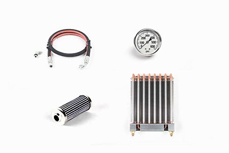
    • Hydraulics
      Hydraulics Shop All
      • Filters
      • Gauges
      • Heat Exchanger
      • Hoses
    • Lubrication
      Lubrication Shop All
      • Bijur Mechanical Lubrication
      • Minimum Lubrication
    • Maintenance
      Maintenance Shop All
      • Grease, Oil, & Sealants
    • Pendant
      Pendant Shop All
      • Floppy Disk & USB
      • Keypad
      • Keys
      • Lens
      • Gaskets & Seals
    • Probing
      Probing Shop All
      • Mill Probing
      • Lathe Tool Presetter
    • Rotary
      Rotary Shop All
      • Rotary Gaskets & Seals
    • Spindles
      Spindles Shop All
      • Couplings
      • Gaskets & Seals
      • Spindle Motor Drive
      • Gearbox Drive
      • Tool Release Piston
    • Tailstock
      Tailstock Shop All
      • Handles
×

Search Results

Web Pages

Images

    • <
    • 1
    • >
MyHaas Welcome,
!
Haas Tooling Guest Order History MyHaas/HaasConnect Sign In Register Haas Tooling My Account Order History Return History MyHaas/HaasConnect Sign Out Welcome, My Machines Latest Activity My Quotes My Account My Users Sign Out
Find Your Distributor
  1. Select Language
    1. English
    2. Deutsch
    3. Español - España
    4. Español - México
    5. Français
    6. Italiano
    7. Português
    8. Český
    9. Dansk
    10. Nederlands
    11. Magyar
    12. Polski
    13. Svenska
    14. Türkçe
    15. 中文
    16. Suomi
    17. Norsk
    18. الإنجليزية
    19. български
    20. Hrvatski
    21. Ελληνικά
    22. Română
    23. Slovenský
    24. Slovenščina
    25. 한국어
    26. 日本語
    27. Українська
×

Search Results

Web Pages

Images

    • <
    • 1
    • >

9 - CAN Bus Systems - Troubleshooting

CAN Bus Systems - Service Manual


  • 1 - CAN Bus Systems - Introduction
  • 2 - CAN Bus Systems - Diagnostics
  • 3 - CAN Systems - Autodoor
  • 4 - CAN Bus Systems - E-Vise
  • 5 - CAN Bus Systems - CAN Lube Panel and Spindle Head
  • 6 - CAN Bus Systems - Compact APL
  • 7 - CAN Bus Systems - Active Ballscrew Compensation
  • 8 - Can Systems - Motion Sensor
  • 9 - CAN Bus Systems - Troubleshooting

Go To :

  • 9.1 CAN Bus Systems
  • 9.2 CAN Lube Panel and Spindle Head
  • 9.3 Compact APL
  • 9.4 Autodoor
  • 9.5 Active Ballscrew Compensation

9.1 CAN Bus Systems Troubleshooting Guide

Introduction

Controller Area Network (CAN) is a robust vehicle bus standard designed to allow microcontrollers and devices to communicate with each other. This method is used to create satellite nodes grouped by function that can be expanded on without changing the core electronics.  

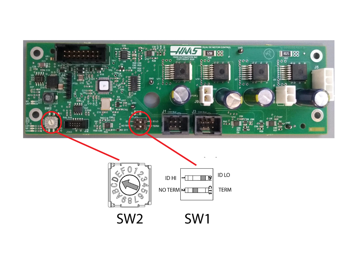
Each board has a node ID selection switch [SW2] that must be set correctly.

Devices are connected in Daisy Chain.

Each board has a termination switch [SW1] that must be set correctly.

Note: The last device on the chain needs to be terminated.

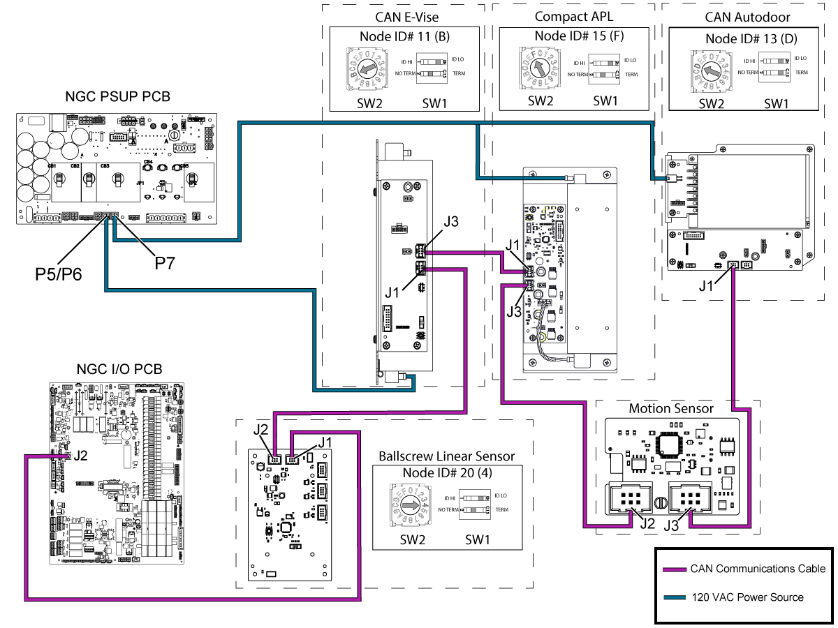
The overall CAN System sequence should be connected in the order that follows: Active Ballscrew Compensation > CAN E-Vise > Compact APL > Motion Sensor > CAN Autodoor.
Important: The CAN system at the end of the sequence will vary by machine and depends on what options the machine has. The last CAN system in the sequence should have their termination switch on the TERM setting. The only exception of this is if the Motion Sensor is the last CAN System in the sequence, this board does not have a termination switch and will need a jumper (PN: 32-1306) installed at J3 if it is the last CAN System.

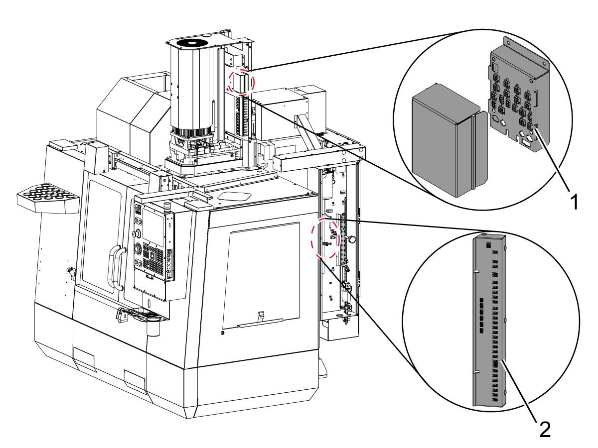
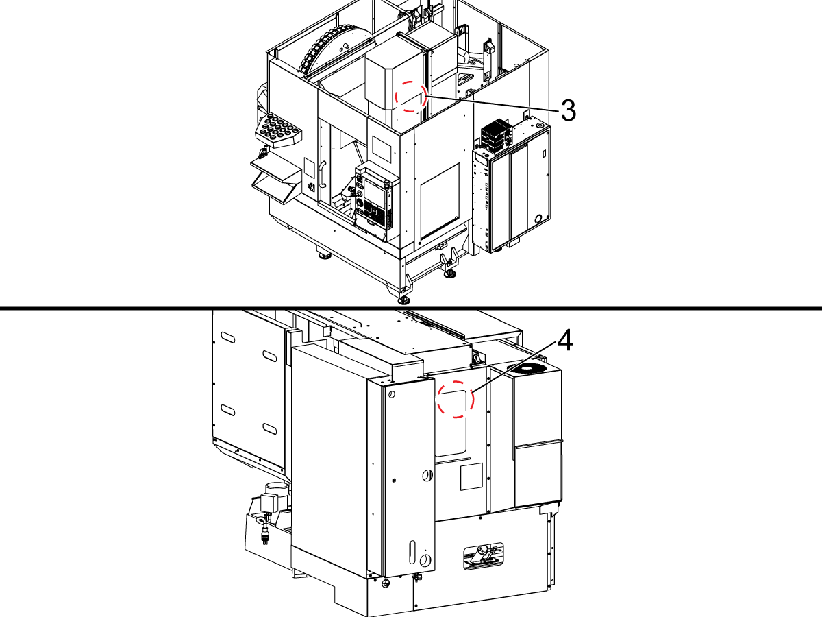
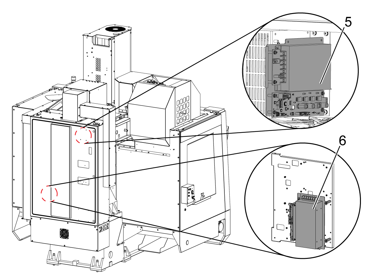
Board Locations

1.  VMC CAN Spindle Head PCB

2. CAN Lube Panel PCB

3.  UMC CAN Spindle Head PCB

4. Lathe CAN Spindle Head PCB

5. CAN Autodoor 

6. CAN E-Vise

Node ID Selection

Device Node ID Factory Setting
IO Board 3 N/A
CAN Autodoor 13 (D on selector) 9013.001
CAN Electric Vise 11 (B on selector) 9011.001
CAN Lube Panel 5 9005.001
CAN Spindle Head 7 9007.001
Legacy CAN Autodoor 9 9009.001
Compact APL 15 (F on the selector) 9015.001
Active Ballscrew Compensation 20 (4 on the selector) 9020.001

Symptom Table

Symptom Possible Cause Corrective Action

ALARM / CAN CODE

BEFORE SOFTWARE 100.21.000.1100:

Alarm 9898.001: CAN NODE WARNING

CAN code [0x43]: CAN NODE WARNING

SOFTWARE 100.21.000.1100 and Later:

Alarm 9706 or (100.001): CAN NODE COMMANDED CURRENT OUT OF RANGE

CAN code [0x43]

Outdated Firmware & Parameters Upgrade to the latest Software, Configuration files, and I/O / CAN AD Firmware.

Alarm 9701: Node ID: XX Node reported it lost communication from I/O board

CAN code [0x01]

Old IO firmware. Load I/O firmware 4.09 or greater.
Poor connection Verify CAN Bus Connectors are fully seated and termination resistor set correctly.
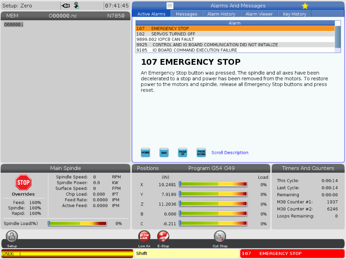
Alarm 9899 IOPCB CAN FAULT and/ or Alarm 9105 IO BOARD COMMAND EXECUTION FAILURE The CAN node I/O Configuration is incorrect. Update the I/O configuration via the I/O Config tab.
The incorrect CAN node is enabled. Verify that Factory Settings 9000.001 -> 9031.001 are set correctly. Only active nodes should be enabled.
The Autodoor CAN PCB does not have power. Verify that the Low Volt Power supply is supplying power to the CAN Autodoor PCB.
The CAN node Communication cable is disconnected. Power down machine for at least a minute. Verify all CAN communication cables are connected correctly.
The CAN Module ID Selector is incorrect. Power down machine for at least a minute. Set ID selector correctly. Power up machine.
The CAN Modules have incorrect termination. Power down machine for at least a minute. Verify that only last node in the chain is terminated. Power up machine.
The CAN Node needs to be reset. Disable CAN Node via 9000.001 -> 9031.001. If the machine recovers (I/O page isn’t “X”) after disabling a particular node, try to enable the node again.
Alarm 9798: IOPCB CAN FCT CRC MISMATCH A test of the internal CRC for the Factory Config Table (FCT) located on one of the CAN devices does not match the CRC for the machines FCT. This can happen due to power failure at a critical time or after replacement of a CAN board attached to the I/O board
  1. Press [POWER OFF].
  2. Put the USB memory device into the control.

    Note: The USB memory device must contain your Haas Control Key and the correct configuration files.

  3. Press [POWER ON].
  4. Press [DIAGNOSTIC].
  5. Go to I/O Config in the Diagnostics tab.
  6. Press [F3] to Update Config Table.
  7. Press [RESET] to continue. If the alarm does not clear, cycle the machine power.

The Main CRC and the Factory CRC are now the same.

BEFORE SOFTWARE 100.21.000.1100:

Alarm 9898.001: CAN NODE WARNING

CAN code [0x43]: Invalid clamp value 

SOFTWARE 100.21.000.1100 and Later:

Alarm 9706: Invalid clamp value

CAN code [0x43]

Outdated autodoor/Evise firmware Update the autodoor/evise to 1.06 or newer

BEFORE SOFTWARE 100.21.000.1100:

Alarm 9898.001: CAN NODE WARNING

CAN code [0x44]: Invalid voltage command

SOFTWARE 100.21.000.1100 and Later:

Alarm 9707: Invalid voltage command

CAN code [0x44]

BEFORE SOFTWARE 100.21.000.1100:

Alarm 9899.001: CAN BUS OFF ERROR

CAN code [0x44]: Invalid voltage command

SOFTWARE 100.21.000.1100 and Later:

Alarm 9700: CAN BUS OFF ERROR

Poor connection Verify CAN Bus Connetors are fully seated and termination resistor set correctly.
Short circuit on CAN Bus

Use multimeter to diagnose short circuit:

  1. Power down machine
  2. Disconnect all nodes
  3. Reconnect nodes one at a time while measuring resistance between CAN lines and 12V and Ground on the connectors
  4. Replace the node that results in a short circuit

Note: It should be 60 ohm between CAN-H and CAN-L

BEFORE SOFTWARE 100.21.000.1100:

9899.002: CAN BUS OFF ERROR

CAN code [0x01]: Node reported it lost communication from I/O board

SOFTWARE 100.21.000.1100 and Later:

Alarm 9701: Node reported it lost communication from I/O board

CAN code [0x01]

Old IO firmware. Load I/O firmware 4.09 or greater.
Poor connection  Verify CAN Bus Connectors are fully seated and termination resistor set correctly.

BEFORE SOFTWARE 100.21.000.1100:

9899.002: CAN BUS OFF ERROR

CAN code [0x30]: I/O board reported it lost communication from node

SOFTWARE 100.21.000.1100 and Later:

Alarm 9702: I/O board reported it lost communication from node

CAN code [0x30]

I/O mapping missing node Verify in I/O Config tab that the node is mapped. Get the latest configuration from portal.
Incorrect node enabled Verify that Factory settings 9000.001 - 9031.001 are only set to true for the nodes that are installed in the machine.
Node ID set incorrectly on node Select correct node ID on ID selection switch. Reboot the machine.
Node lost power Use a multimeter to verify that the node has power. Replace the power supply if necessary.
Poor connection Verify that the CAN Bus Connectors are fully seated and that the termination resistor set correctly.

BEFORE SOFTWARE 100.21.000.1100:

Alarm 9899.003: CAN BUS OFF ERROR

SOFTWARE 100.21.000.1100 and Later:

Alarm 9703: CAN NODE ERROR

Node Fatal alarm. Firmware has a non-recoverable alarm. Cycle node enable (90nn.001) or update config table in I/O page. The machine may need to be rebooted.
Alarm 9713: NODE APPLICATION CORRUPTED I/O Board has detected a CAN device with corrupted application&nbsp;firmware. Try updating the firmware for the affected CAN device.
Alarm 9714: NODE BOOTLOADER CORRUPTED I/O Board has detected a CAN device with corrupted bootloader firmware.
Try updating the firmware for the affected CAN device.
ALARM 966 EXCESSIVE TOOL IMBALANCE (board accelerometer) Excessive tool vibration is generated by on board accelerometer Verify that everything is properly balanced, such as tools and spindles

Reduce sensitivity using Setting 245

  • Setting 245 = Normal: Means that parameter 856 is directly used
  • Setting 245 = Low: Means that parameter 856 is multiplied by 1.5
  • Setting 245 = Off: Alarm 966 will not be thrown. 

NOTE: Setting 245 will not persist when the power is cycled

Please refer to the  Accelerometer Troubleshooting Guide for further information

ALARM 9941 CRASH DETECTED (spindle head accelerometer)  The machine detected a crash Verify the program machine movements to make sure the machine does not crash
The Accelerometer unit, cable or spindle head CAN board is damaged
  • Verify analog inputs are not 0 (cable unplugged)
  • I/O board minimum version 4.09 (update to latest if possible)
  • Spindle head CAN board minimum 1.10 (update to latest if possible
  • Make sure to take an error report (SHIFT+F3), error reports will have information about the crash direction and magnitude in the JavaConsoleLog.txt file (refer to Crash Detection Section in the Accelerometer Troubleshooting Guide for further information)

Electrical Diagrams

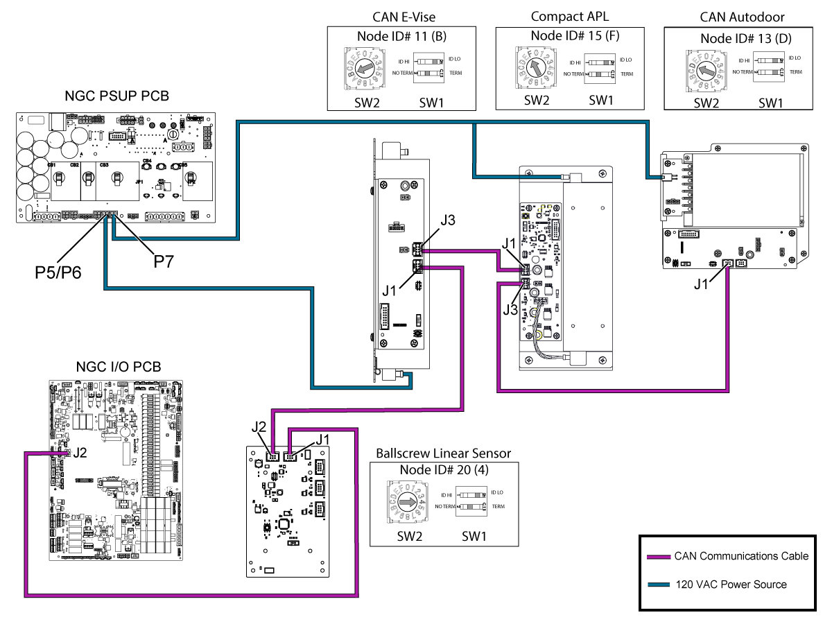
CAN Bus sequence when a machine has Active Ballscrew Compensation, CAN E-Vise, Compact APL, Motion Sensor, and CAN Autodoor.


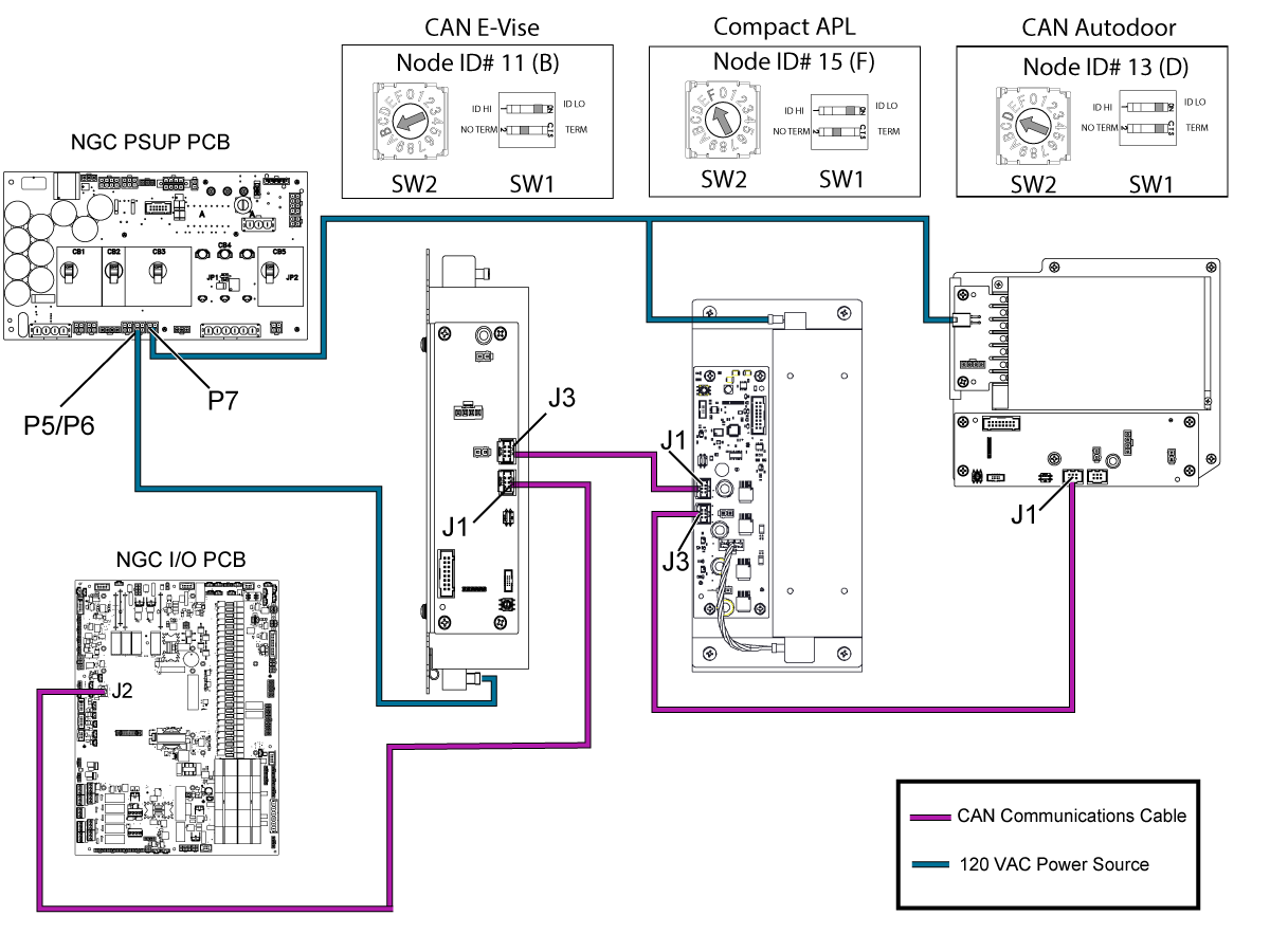
CAN Bus sequence when a machine has a CAN E-Vise, Compact APL, and CAN Autodoor.


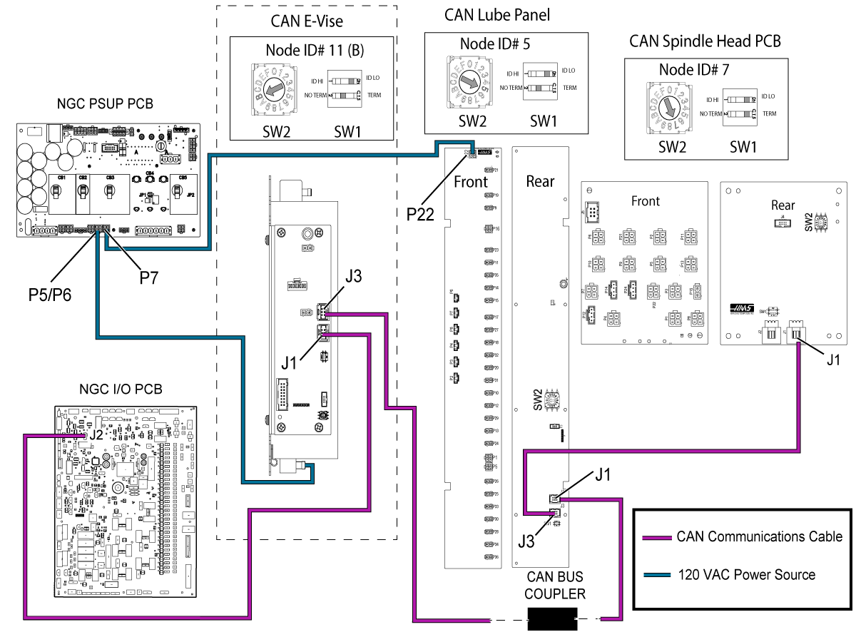
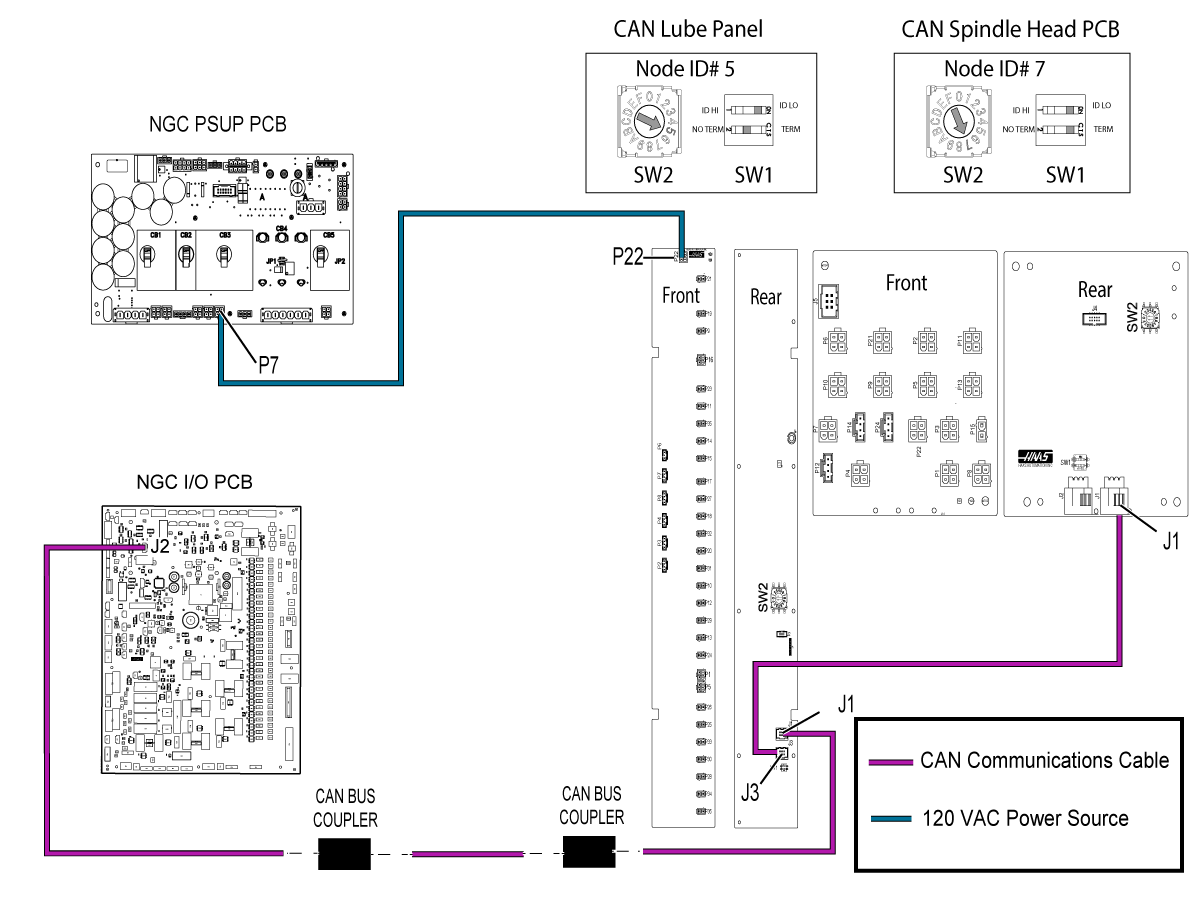
The CAN Lube Panel and CAN Spindle Head PCB diagram with a CAN Autodoor and a CAN E-Vise


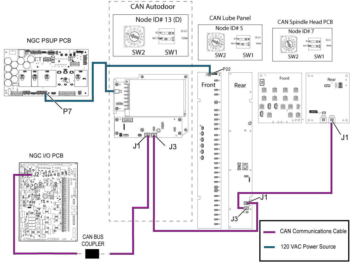
The CAN Lube Panel and CAN Spindle Head PCB diagram with a CAN Autodoor and without a CAN E-Vise


The CAN Lube Panel and CAN Spindle Head PCB diagram with a CAN E-Vise, but without a CAN Autodoor


The CAN Lube Panel and CAN Spindle Head PCB diagram without a CAN Autodoor or CAN E-Vise

Related Content

Smart CAN Autodoor TSG
CAN Lube Panel and Spindle Head TSG
DIagnostic Data
Firmware Update
I/O Troubleshooting

9.2 CAN Lube Panel and Spindle Head Troubleshooting Guide

Introduction

Controller Area Network (CAN) is a robust vehicle bus standard designed to allow microcontrollers and devices to communicate with each other. This method is used to create satellite nodes grouped by function that can be expanded on without changing the core electronics.

  • Each board has a node ID selection switch [SW2] that must be set correctly.
  • Devices are connected in Daisy Chain.
  • Each board has a termination switch [SW1] that much be set correctly.

Note: The last device on the chain needs to be terminated.

Board Locations

1.  VMC CAN Spindle Head PCB

2. CAN Lube Panel PCB

3.  UMC CAN Spindle Head PCB

4. Lathe CAN Spindle Head PCB

Node ID Selection

Device Node ID Factory Setting
IO Board 3 N/A
CAN Autodoor 13 (D on selector) 9013.001
CAN Electric Vise 11 (B on selector) 9011.001
CAN Lube Panel 5 9005.001
CAN Spindle Head 7 9007.001
Legacy CAN Autodoor 9 9009.001
Compact APL 15 (F on the selector) 9015.001
Active Ballscrew Compensation 20 (4 on the selector) 9020.001

Symptom Table

Alarm / CAN code

Before Software 100.21.000.1100

Alarm / CAN code

After Software 100.21.000.1100

Possible Cause Corrective Action

Alarm 9105: IO BOARD COMMAND EXECUTION FAILURE

The machine outputs the following alarms with this alarm:

  • 2001.003: EMERGENCY STOP SWITCH ERROR
  • 2002: OPERATOR'S PENDANT EMERGENCY STOP SWITCH ERROR
  • 120: LOW AIR PRESSURE OR FLOW


Outdated main I/O firmware.

Updated the main I/O firmware to the latest version.

Refer to the Firmware Update procedure.

Alarm 9899 IOPCB CAN FAULT and/ or 9105 IO BOARD COMMAND EXECUTION FAILURE The CAN node I/O Configuration is incorrect. Update the I/O configuration via the I/O Config tab.
The incorrect CAN node is enabled. Verify that Factory Settings 9000.001 -> 9031.001 are set correctly. Only active nodes should be enabled.
The Spindle Head or Lube Panel CAN PCB does not have power. Verify that the Low Volt Power supply is supplying power to the CAN Spindle Head or Lube Panel PCB.
The CAN node Communication cable is disconnected. Power down machine for at least a minute. Verify all CAN communication cables are connected correctly.
The CAN Module ID Selector is incorrect. Power down machine for at least a minute. Set ID selector correctly. Power up machine.
The CAN Modules have incorrect termination. Power down machine for at least a minute. Verify that only last node in the chain is terminated. Power up machine.
The CAN Node needs to be reset. Disable CAN Node via 9000.001 -> 9031.001. If the machine recovers (I/O page isn’t “X”) after disabling a particular node, try to enable the node again.
Alarm 9798: IOPCB CAN FCT CRC MISMATCH A test of the internal CRC for the Factory Config Table (FCT) located on one of the CAN devices does not match the CRC for the machines FCT. This can happen due to power failure at a critical time or after replacement of a CAN board attached to the I/O board
  1. Press [POWER OFF].
  2. Put the USB memory device into the control.

    Note: The USB memory device must contain your Haas Control Key and the correct configuration files.

  3. Press [POWER ON].
  4. Press [DIAGNOSTIC].
  5. Go to I/O Config in the Diagnostics tab.
  6. Press [F3] to Update Config Table.
  7. Press [RESET] to continue. If the alarm does not clear, cycle the machine power.

The Main CRC and the Factory CRC are now the same.


Alarm 9898.001: CAN NODE WARNING

CAN code [0x41]: Invalid command for motor 1

Alarm 9704: Invalid command for motor 1

CAN code [0x41]

TBD TBD

Alarm 9898.001: CAN NODE WARNING

CAN code [0x42]: Invalid command for motor 2

Alarm 9705: Invalid command for motor 2

CAN code [0x42]

TBD TBD

Alarm 9898.001: CAN NODE WARNING

CAN code [0x43]: Invalid clamp value 

Alarm 9706: Invalid clamp value

CAN code [0x43]

Outdated autodoor/Evise firmware Update the autodoor/evise to 1.06 or newer

Alarm 9898.001: CAN NODE WARNING

CAN code [0x44]: Invalid voltage command

Alarm 9707: Invalid voltage command

CAN code [0x44]

Alarm 9898.001: CAN NODE WARNING

CAN code [0x81]: Motor 1 shorted

or

Alarm 9898.001: CAN NODE WARNING

CAN code [0x82]: Motor 2 shorted

Alarm 9708: Motor 1 shorted

CAN code [0x81]

or

Alarm 9709: Motor 2 shorted

CAN code [0x82]

Cable Failure Replace the motor cable.
Board Failure Replace the Autodoor/Evise board. 
Motor Failure Replace the motor.
Alarm 9899.001: CAN BUS OFF ERROR Alarm 9700: CAN BUS OFF ERROR Poor connection Verify CAN Bus Connetors are fully seated and termination resistor set correctly.
Short circuit on CAN Bus

Use multimeter to diagnose short circuit:

  1. Power down machine
  2. Disconnect all nodes
  3. Reconnect nodes one at a time while measuring resistance between CAN lines and 12V and Ground on the connectors
  4. Replace the node that results in a short circuit

Note: It should be 60 ohm between CAN-H and CAN-L

Alarm 9899.002: CAN BUS OFF ERROR

CAN code [0x01]: Node reported it lost communication from I/O board

Alarm 9701: Node reported it lost communication from I/O board

CAN code [0x01]

Old IO firmware. Load I/O firmware 4.09 or greater.
Poor connection  Verify CAN Bus Connectors are fully seated and termination resistor set correctly.
 

Alarm 9899.002: CAN BUS OFF ERROR

CAN code [0x30]: I/O board reported it lost communication from node

Alarm 9702: I/O board reported it lost communication from node

CAN code [0x30]

I/O mapping missing node Verify in I/O Config tab that the node is mapped. Get the latest configuration from portal.
Incorrect node enabled Verify that Factory settings 9000.001 - 9031.001 are only set to true for the nodes that are installed in the machine.
Node ID set incorrectly on node Select correct node ID on ID selection switch. Reboot the machine.
Node lost power Use a multimeter to verify that the node has power. Replace the power supply if necessary.
Poor connection Verify that the CAN Bus Connectors are fully seated and that the termination resistor set correctly.
Alarm 9899.003: CAN BUS OFF ERROR Alarm 9703: CAN BUS OFF ERROR Node Fatal alarm. Firmware has a non-recoverable alarm. Cycle node enable (90nn.001) or update config table in I/O page. The machine may need to be rebooted.

Alarm 9898.001: CAN NODE WARNING

unrecognized CAN code

Alarm 9712: CAN NODE WARNING

unrecognized CAN code

TBD TBD

Alarm 9899.002: CAN BUS OFF ERROR

unrecognized CAN code

Alarm 9711: CAN BUS OFF ERROR

unrecognized CAN code

TBD TBD

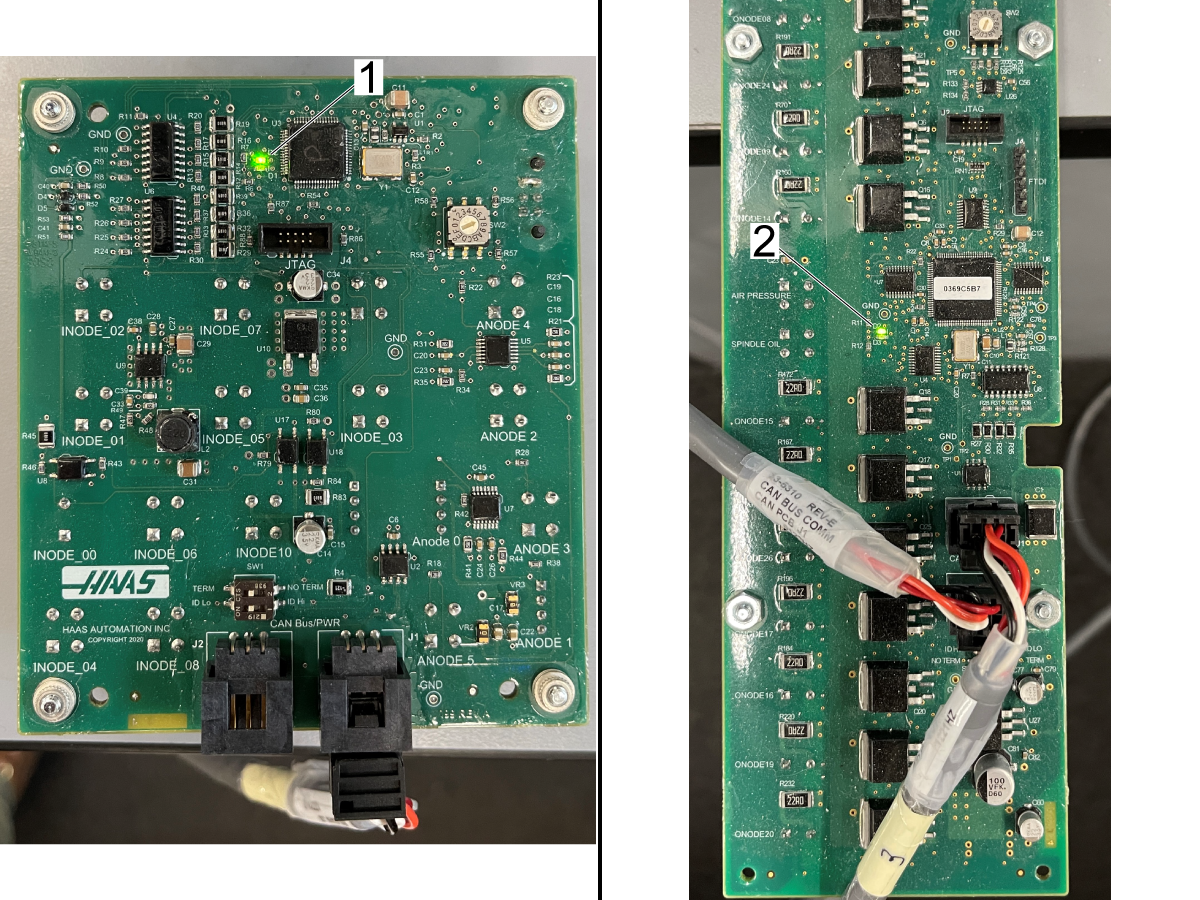
Spindle Head & Lube Panel PCB Status LEDs

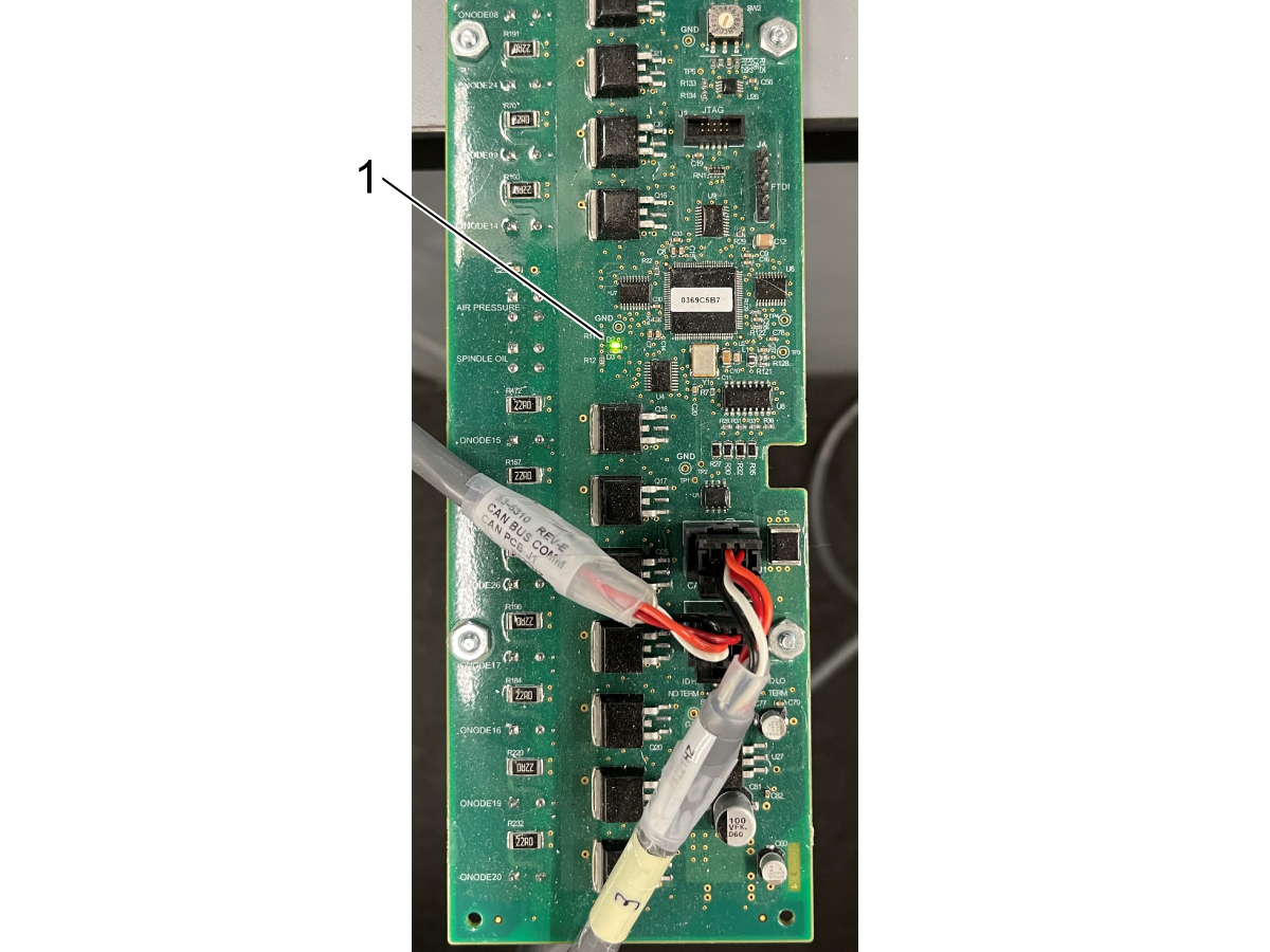
Spindle Head Status LED Locations

Lube Panel Satus LED Locations

PCB State Mode

Red LED

Green LED

Bootloader N/A

Off

On

Application Deactive (Node Disabled)

Off

Blinking 1 Hz

Active (Node Enabled)

Off

Blinking 2-5 Hz

Safe Mode

Blinking 2-5 Hz

Off

Dead Node

On

On

CAN Spindle Head & Lube Panel Troubleshooting

1

Problem: Machines with SW Version 100.21.000.1003 and earlier: Alarm 9899.002: Node ID: XX [0x30] IOPCB CAN FAULT or other 9899 CAN Bus alarms.

Machines with SW Version 100.21.000.1100 and later: Alarm 9702: I/O board reported it lost communication from node CAN code [0x30] or other CAN Bus alarms.

After cycle powering the machine, alarm 9105 IO BOARD COMMAND EXECUTION FAILURE is generated and other I/O & CAN alarms. Analog sensors all read zero.

Cause: Communication between the IO PCB and CAN bus PCB was lost. This can be caused by a communication interruption or because the CAN bus PCB or the CAN power supply has failed.

2

Update software, IO Firmware, and all CAN devices displayed that can be updated to the latest. If the node is damaged or disconnected it may not display on the list of nodes. All nodes are displayed on the Firmware Updates page[1]. The Spindle Head node is missing from the page[2], indicating that there may be an issue with that node.

After cycle powering with the E-Stop pressed, press reset to restore I/O PCB. Note any CAN or I/O alarms after pressing reset.

3

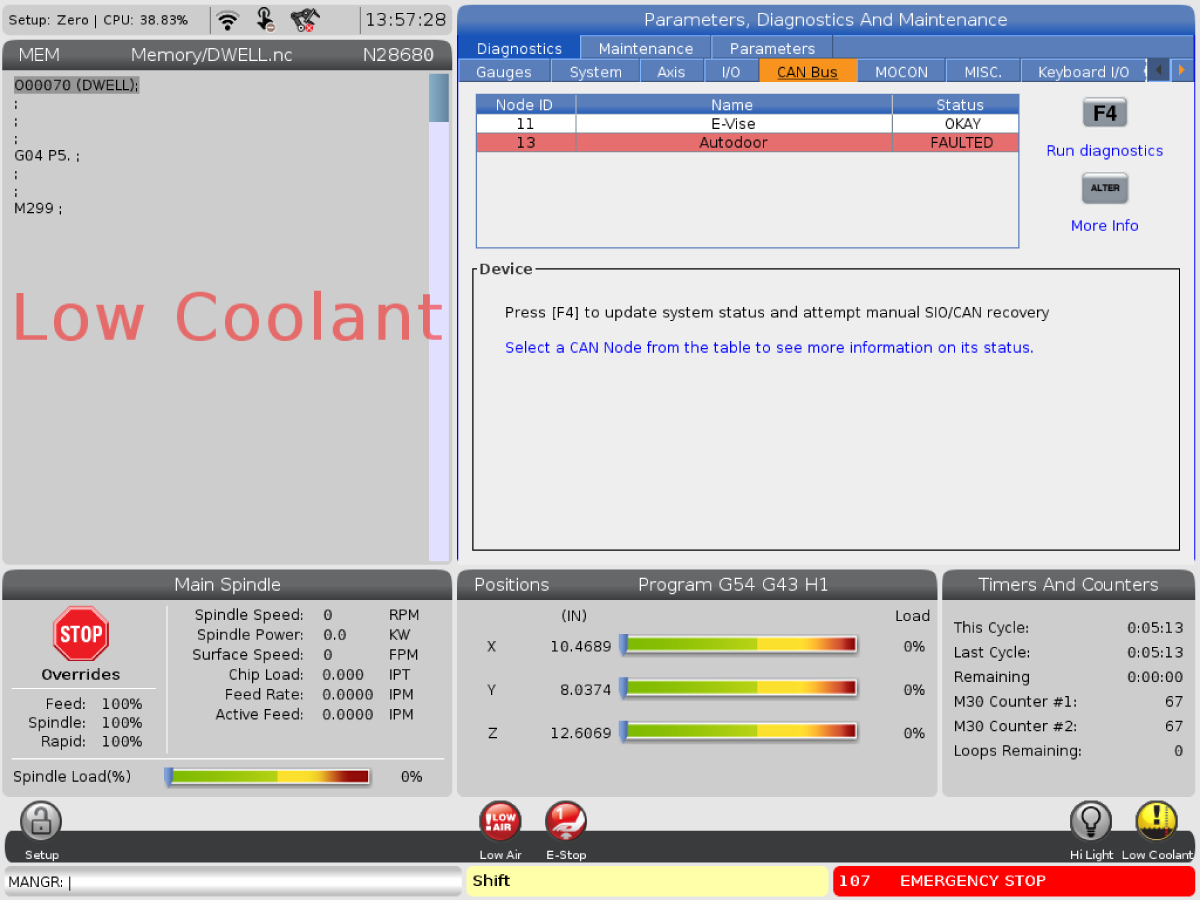
Navigate to the CAN Bus Diagnostic page. This requires a service key. Note the status of each node, do the faulted nodes correspond to the node displayed in the CAN alarm. Press F4 to Run Diagnostics.

If a single node at the end of the chain or in the middle of the chain is in a fault state, troubleshoot that PCB.

If two or more nodes are faulted, troubleshoot the first faulted node in the chain closest to the I/O PCB then move to the last.

4

Access the PCB and check the status lights. Spindle Head PCB LED location[1]. Lube Panel PCB LED location[2].

PCB State

Mode

Red LED

Green LED

Bootloader

N/A

Off

On

Application

Deactive (Node Disabled) - Fault State

Off

Blinking 1 Hz

Active (Node Enabled) - Normal State

Off

Blinking 2-5 Hz

Safe Mode - Fault State

Blinking 2-5 Hz

Off

Dead Node -  Fault State

On

On

Spindle Head & Lube Panel PCB Status LEDs

5

If the Status LEDs are in a fault state, check the node ID selector and termination. If incorrect, power down the machine and change the node ID selector to the correct node ID and set the termination based on the machine configuration and the CAN devices installed on the machine.

With the machine powered down inspect the cables and disconnect and reconnect cables and CAN Bus couplers.

Power up the machine and check the CAN Bus page and press F4 to Run Diagnostics.

If the faulted nodes are the E-Vise or Auto Door, disable the node and verify that alarms clear.

Warning: Do not disable the Spindle Head or Lube Panel and run the machine. Damage or injury can occur.

Electrical Diagrams

The CAN Lube Panel and CAN Spindle Head PCB diagram with a CAN Autodoor and a CAN E-Vise


The CAN Lube Panel and CAN Spindle Head PCB diagram with a CAN Autodoor and without a CAN E-Vise


The CAN Lube Panel and CAN Spindle Head PCB diagram with a CAN E-Vise, but without a CAN Autodoor


The CAN Lube Panel and CAN Spindle Head PCB diagram without a CAN Autodoor or CAN E-Vise

Related Content

I/O Troubleshooting
Smart CAN Autodoor TSG
DIagnostic Data
Firmware Update
CAN Bus Systems TSG

9.3 Compact APL Troubleshooting Guide

Introduction

Controller Area Network (CAN) is a robust vehicle bus standard designed to allow microcontrollers and devices to communicate with each other. This method is used to create satellite nodes grouped by function that can be expanded on without changing the core electronics.

  • Each board has a node ID selection switch [SW2] that must be set correctly.
  • Devices are connected in Daisy Chain.
  • Each board has a termination switch [SW1] that much be set correctly.

Note: The last device on the chain needs to be terminated.

Node ID Selection

Device Node ID Factory Setting
IO Board 3 N/A
CAN Autodoor 13 (D on selector) 9013.001
CAN Electric Vise 11 (B on selector) 9011.001
CAN Lube Panel 5 9005.001
CAN Spindle Head 7 9007.001
Legacy CAN Autodoor 9 9009.001
Compact APL 15 (F on the selector) 9015.001
Active Ballscrew Compensation 20 (4 on the selector) 9020.001

Symptom Table

Alarm / CAN code

Possible Cause Corrective Action

Alarm 9105: IO BOARD COMMAND EXECUTION FAILURE

The machine outputs the following alarms with this alarm:

  • 2001.003: EMERGENCY STOP SWITCH ERROR
  • 2002: OPERATOR'S PENDANT EMERGENCY STOP SWITCH ERROR
  • 120: LOW AIR PRESSURE OR FLOW
Outdated main I/O firmware.

Updated the main I/O firmware to the latest version.

Refer to the Firmware Update procedure.

Alarm 17.9920/18.9920: POSITION ERROR TOO LARGE Electrical connections to the C-APL AV or AU servo amplifiers may be swapped.
Reference the C-APL electrical schematic below.
Alarm 9899: IOPCB CAN FAULT and/ or 9105: IO BOARD COMMAND EXECUTION FAILURE The CAN node I/O Configuration is incorrect. Update the I/O configuration via the I/O Config tab.
The incorrect CAN node is enabled. Verify that Factory Settings 9000.001 -> 9031.001 are set correctly. Only active nodes should be enabled.
The CAN PCB does not have power. Verify that the Low Volt Power supply is supplying power to the CAN PCB.
The CAN node Communication cable is disconnected. Power down machine for at least a minute. Verify all CAN communication cables are connected correctly.
The CAN Module ID Selector is incorrect. Power down machine for at least a minute. Set ID selector correctly. Power up machine.
The CAN Modules have incorrect termination. Power down machine for at least a minute. Verify that only last node in the chain is terminated. Power up machine.
The CAN Node needs to be reset. Disable CAN Node via 9000.001 -> 9031.001. If the machine recovers (I/O page isn’t “X”) after disabling a particular node, try to enable the node again.
Alarm 9798: IOPCB CAN FCT CRC MISMATCH A test of the internal CRC for the Factory Config Table (FCT) located on one of the CAN devices does not match the CRC for the machines FCT. This can happen due to power failure at a critical time or after replacement of a CAN board attached to the I/O board
  1. Press [POWER OFF].
  2. Put the USB memory device into the control.

    Note: The USB memory device must contain your Haas Control Key and the correct configuration files.

  3. Press [POWER ON].
  4. Press [DIAGNOSTIC].
  5. Go to I/O Config in the Diagnostics tab.
  6. Press [F3] to Update Config Table.
  7. Press [RESET] to continue. If the alarm does not clear, cycle the machine power.

The Main CRC and the Factory CRC are now the same.


Alarm 9704: CAN NODE INVALID COMMAND FOR MOTOR 1

CAN code [0x41]

Motor was commanded on in both directions simultaneously. If using Macro programming, verify G-Code is not turning on both outputs.

Alarm 9706: CAN NODE COMMANDED CURRENT OUT OF RANGE

CAN code [0x43]

Outdated CAN Board firmware. Update the CAN Board latest CAN firmware.

Alarm 9707: CAN NODE INVALID MAX VOLTAGE

CAN code [0x44]

Alarm 9708: CAN NODE MOTOR 1 SHORT DETECTED

CAN code [0x81]

Cable Failure Replace the motor cable.
Board Failure Replace the Autodoor/Evise board. 
Motor Failure Replace the motor.
Alarm 9700: CAN BUS OFF ERROR Poor connection Verify CAN Bus Connetors are fully seated and termination resistor set correctly.
Short circuit on CAN Bus

Use multimeter to diagnose short circuit:

  1. Power down machine
  2. Disconnect all nodes
  3. Reconnect nodes one at a time while measuring resistance between CAN lines and 12V and Ground on the connectors
  4. Replace the node that results in a short circuit

Note: It should be 60 ohm between CAN-H and CAN-L

Alarm 9701: CAN NODE LOST COMMUNICATION WITH IO

CAN code [0x01]

Old IO firmware. Load I/O firmware 4.09 or greater.
Poor connection  Verify CAN Bus Connectors are fully seated and termination resistor set correctly.
Alarm 9702: IO LOST COMMUNICATION WITH CAN NODE

CAN code [0x30]

I/O mapping missing node Verify in I/O Config tab that the node is mapped. Get the latest configuration from portal.
Incorrect node enabled Verify that Factory settings 9000.001 - 9031.001 are only set to true for the nodes that are installed in the machine.
Node ID set incorrectly on node Select correct node ID on ID selection switch. Reboot the machine.
Node lost power Use a multimeter to verify that the node has power. Replace the power supply if necessary.
Poor connection Verify that the CAN Bus Connectors are fully seated and that the termination resistor set correctly.

Alarm 9703: 
INTERNAL FAULT
 
Node Fatal alarm. Firmware has a non-recoverable alarm. Cycle node enable (90nn.001) or update config table in I/O page. The machine may need to be rebooted.
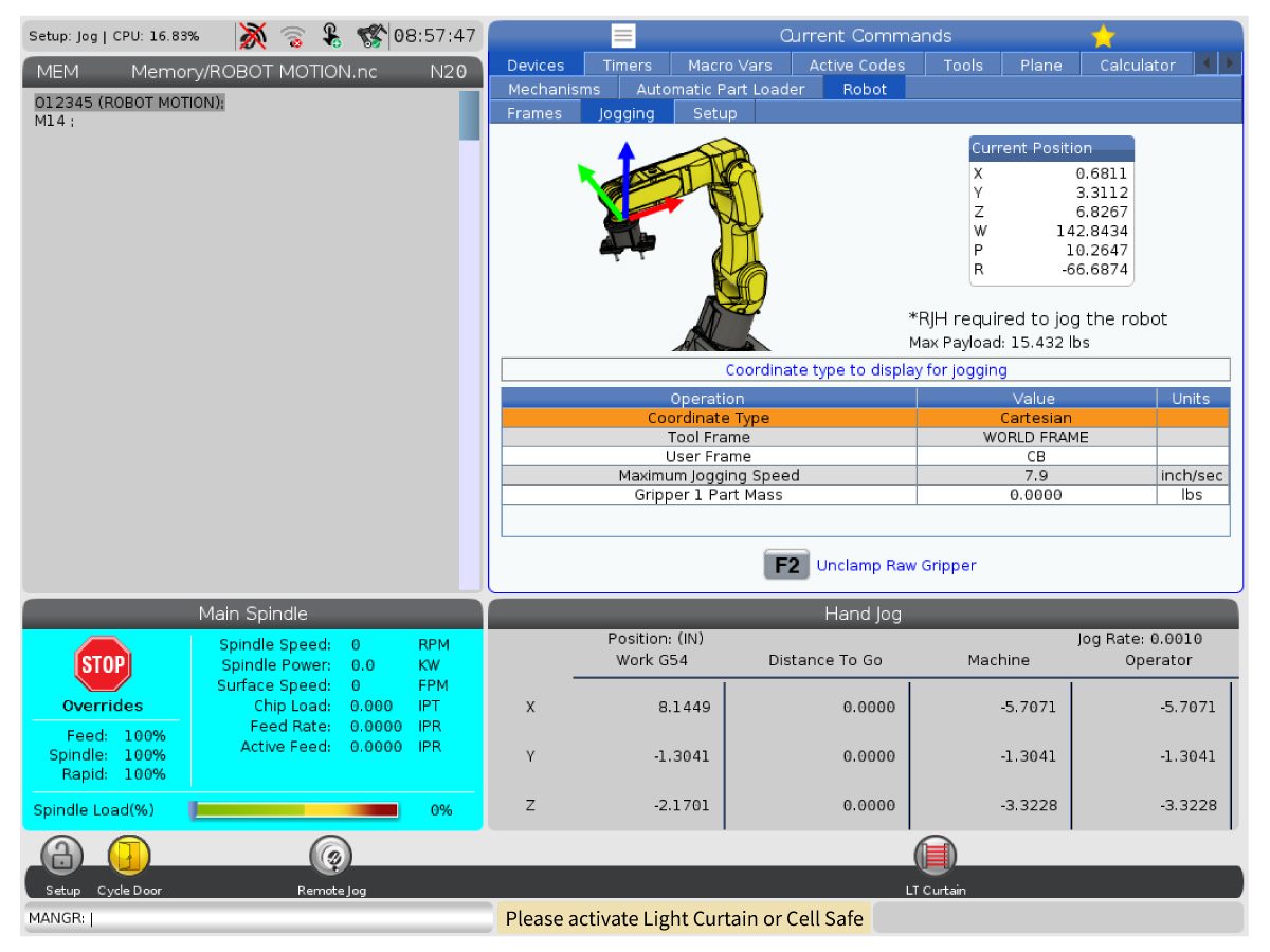
When trying to run the machine a yellow warning message appears saying "Please activate Light Curtain or Cell Safe". The correct safety parameter kit has not been applied to the machine. Order the corresponding Front Automation Safety or Side Automation Safety kits (93-1000997 or 93-1000996) and re-upload the configuration files from HBC.

Electrical Diagrams

Compact APL Electrical Schematic


CAN Bus sequence when a machine has a CAN E-Vise, Compact APL, and CAN Autodoor.


CAN Bus sequence when a machine has Active Ballscrew Compensation, CAN E-Vise, Compact APL, Motion Sensor, and CAN Autodoor.

Related Content

I/O Troubleshooting
Smart CAN Autodoor TSG
CAN Lube Panel and Spindle Head TSG
DIagnostic Data
Firmware Update
CAN Bus Systems TSG

9.4 Autodoor

Autodoor - Service Manual

Click on the image below to take you to the Autodoor - Service Manual

9.5 Active Ballscrew Compensation Troubleshooting Guide

Introduction

Controller Area Network (CAN) is a robust vehicle bus standard designed to allow microcontrollers and devices to communicate with each other. This method is used to create satellite nodes grouped by function that can be expanded on without changing the core electronics.  

Each board has a node ID selection switch [SW2] that must be set correctly.

Devices are connected in Daisy Chain.

Each board has a termination switch [SW1] that much be set correctly.

Note: The last device on the chain needs to be terminated.

Overview

The Active Ballscrew Compensation is made up of:

  1. Linear Gauge Sensor - The sensor assembly is installed at the end of the ballscrew.
  2. CAN Node Box - CAN node box that feeds the information from the sensor to the CAN hub board.
  3. Linear Gauge Hub Board -CAN board the sends feedback info from the sensor to the IO board.

Each Axis will have its own Linear Gauge Sensor [1] and CAN Node Box [2] that will connect to the CAN Hub Board [3]. 

The cables coming from each of the axis' CAN Node Box will connect to the following ports on the CAN Hub Board:

  • X-Axis: Sensor 1 Port
  • Y-Axis: Sensor 2 Port
  • Z-Axis: Sensor 3 Port

At this time Active Ballscrew Compensation is an option on the following machines and their variants:

  • VF-6/7/8/9/10/11/12/14
  • VR-8/9/11/14
  • VM-6

Node ID Selection

Device Node ID Factory Setting
IO Board 3 N/A
CAN Autodoor 13 (D on selector) 9013.001
CAN Electric Vise 11 (B on selector) 9011.001
CAN Lube Panel 5 9005.001
CAN Spindle Head 7 9007.001
Legacy CAN Autodoor 9 9009.001
Compact APL 15 (F on the selector) 9015.001
Active Ballscrew Compensation 20 (4 on the selector) 9020.001

Symptom Table

Alarm / CAN code

Possible Cause Corrective Action
Cannot upgrade the CAN board firmware. The I/O board has a firmware version earlier than 4.24. Upgrade the I/O firmware to 4.24 or higher. Try upgrading the CAN board firmware after the I/O firmware is upgraded.
Alarm 9417: LINEAR SENSOR FAULT DETECTED Invalid reading from linear sensor has been detected. The sensor may be disconnected. Verify all hardware connections are secure and correct Refer to the Overview section above for all the components in the system, the wiring diagram can be found below for where it lies within the CAN system.

Alarm 9105: IO BOARD COMMAND EXECUTION FAILURE

The machine outputs the following alarms with this alarm:

  • 2001.003: EMERGENCY STOP SWITCH ERROR
  • 2002: OPERATOR'S PENDANT EMERGENCY STOP SWITCH ERROR
  • 120: LOW AIR PRESSURE OR FLOW
Outdated main I/O firmware.

Updated the main I/O firmware to the latest version.

Refer to the Firmware Update procedure.

Alarm 9899: IOPCB CAN FAULT and/ or 9105: IO BOARD COMMAND EXECUTION FAILURE The CAN node I/O Configuration is incorrect. Update the I/O configuration via the I/O Config tab.
The incorrect CAN node is enabled. Verify that Factory Settings 9000.001 -> 9031.001 are set correctly. Only active nodes should be enabled.
The CAN node Communication cable is disconnected. Power down the machine for at least a minute. Verify all CAN communication cables are connected correctly.
The CAN Module ID Selector is incorrect. Power down the machine for at least a minute. Set ID selector correctly. Power up machine.
The CAN Modules have incorrect termination. Power down the machine for at least a minute. Verify that only the last node in the chain is terminated. Power up machine.
The CAN Node needs to be reset. Disable CAN Node via 9000.001 -> 9031.001. If the machine recovers (I/O page is not “X”) after disabling a particular node, try to enable the node again.
Alarm 9798: IOPCB CAN FCT CRC MISMATCH A test of the internal CRC for the Factory Config Table (FCT) located on one of the CAN devices does not match the CRC for the machines FCT. This can happen due to power failure at a critical time or after replacement of a CAN board attached to the I/O board
  1. Press [POWER OFF].
  2. Put the USB memory device into the control.

    Note: The USB memory device must contain your Haas Control Key and the correct configuration files.

  3. Press [POWER ON].
  4. Press [DIAGNOSTIC].
  5. Go to I/O Config in the Diagnostics tab.
  6. Press [F3] to Update Config Table.
  7. Press [RESET] to continue. If the alarm does not clear, cycle the machine power.

The Main CRC and the Factory CRC are now the same.


Alarm 9701: CAN NODE LOST COMMUNICATION WITH IO

CAN code [0x01]

Old IO firmware. Load I/O firmware 4.09 or greater.
Poor connection  Verify CAN Bus Connectors are fully seated, and termination resistor set correctly.
Alarm 9702: IO LOST COMMUNICATION WITH CAN NODE

CAN code [0x30]

I/O mapping missing node Verify in I/O Config tab that the node is mapped. Get the latest configuration from portal.
Incorrect node enabled Verify that Factory settings 9000.001 - 9031.001 are only set to true for the nodes that are installed in the machine.
Node ID set incorrectly on node Select correct node ID on ID selection switch. Reboot the machine.
Poor connection Verify that the CAN Bus Connectors are fully seated, and that the termination resistor set correctly.

Alarm 9703:
CAN NODE ERROR
 
Node Fatal alarm. Firmware has a non-recoverable alarm. Cycle node enable (90nn.001) or update config table in I/O page. The machine may need to be rebooted.

Alarm 9737.00X: Linear Sensor Error

Sub-codes:
.001 = X-Axis
.002 = Y-Axis
.003 = Z-Axis

The sensor node has lost communication with the linear sensor. This may be due to a faulty sensor or loose connection to the Node.

1. Verify the cable connection of the linear sensor to the node.

2. Under the diagnostics tab, navigate to the I/O page, and check the analog input for the axis generating the alarm.

  • A-Input 27 = X-axis
  • A-Input 28 = Y-axis
  • A-Input 31 = Z-axis

3. If possible, apply pressure to the switch by hand to see if the analog value increases as the switch is pushed in. Verify the input is not constantly 0.

4. Also verify that the input is not fluctuating when a constant/no pressure is applied to the switch. 

Wiring Diagram

CAN Bus sequence when a machine has a Ballscrew Linear Sensor, CAN E-Vise, Compact APL, and CAN Autodoor.


CAN Bus sequence when a machine has Active Ballscrew Compensation, CAN E-Vise, Compact APL, Motion Sensor, and CAN Autodoor.

Recently Viewed Items

You Have No Recently Viewed Items Yet

Feedback
Haas Logo

美元价格不包括关税、报关费用、保险费、增值税及运费。
USD prices DO NOT include customs duty, customs fees, insurance, VAT, or freight.

人民币价格包含关税、报关费用、货运保险和增值税, 但不包括运费。
CNY prices include customs duty, customs fees, insurance, and VAT. DOES NOT include freight.

Haas Delivered Price

This price includes shipping cost, export and import duties, insurance, and any other expenses incurred during shipping to a location in France agreed with you as a buyer. No other mandatory costs can be added to the delivery of a Haas CNC Product.

KEEP UP WITH THE LATEST HAAS TIPS AND TECHNOLOGY...

Sign up now!   

HAAS TOOLING ACCEPTS THE FOLLOWING:

  • Service & Support
  • Owners
  • Request Service
  • Operator Manuals
  • Haas Parts
  • Rotary Repair Request
  • Pre-Install Guides
  • Shopping Tools
  • Build & Price a New Haas
  • Available Inventory
  • The Haas Price List
  • CNCA Financing
  • About Haas
  • DNSH Statement
  • Careers
  • Certifications & Safety
  • Contact Us
  • History
  • Terms & Conditions
  • Haas Tooling Terms & Conditions
  • Privacy
  • Warranty
  • Haas Community
  • Haas Certification Program
  • Haas Motorsports
  • Gene Haas Foundation
  • Haas Technical Education Community
  • Events
  • Join the Conversation
  • Facebook
  • X
  • Flickr
  • YouTube
  • LinkedIn
  • Instagram
  • TikTok
© 2025 Haas Automation, Inc – CNC Machine Tools

This site is protected by reCAPTCHA and the Google Privacy Policy and Terms of Service apply.

2800 Sturgis Rd., Oxnard, CA 93030
Toll Free: (888) 817-4446 / Fax: 805-278-8554