MyHaas Welcome,
!
Haas Tooling Guest Order History MyHaas/HaasConnect Sign In Register Haas Tooling My Account Order History Return History MyHaas/HaasConnect Sign Out Welcome, My Machines Latest Activity My Quotes My Account My Users Sign Out
Find Your Distributor
  1. Select Language
    1. English
    2. Deutsch
    3. Español - España
    4. Español - México
    5. Français
    6. Italiano
    7. Português
    8. Český
    9. Dansk
    10. Nederlands
    11. Magyar
    12. Polski
    13. Svenska
    14. Türkçe
    15. 中文
    16. Suomi
    17. Norsk
    18. الإنجليزية
    19. български
    20. Hrvatski
    21. Ελληνικά
    22. Română
    23. Slovenský
    24. Slovenščina
    25. 한국어
    26. 日本語
    27. Українська
  • machines Main Menu
    • Haas Vertical Mills Vertical Mills
      Vertical Mills
      Vertical Mills View All
      • Vertical Mills
      • VF Series
      • Universal Machines
      • VR Series
      • VP-5 Prismatic
      • Pallet-Changing VMCs
      • Mini Mills
      • Mold Machines
      • High-Speed Drill Centers
      • Drill/Tap/ Mill Series
      • Toolroom Mills
      • Compact Mills
      • Gantry Series
      • SR Sheet Routers
      • Extra-Large VMC
      • Double-Column Mills
      • Control Simulator
      • Mill Automatic Parts Loader
      • VMC/UMC Side-Loading Automatic Parts Loader
      • Compact Automatic Parts Loader
    • Product Image Multi-Axis Solutions
      Multi-Axis Solutions
      Multi-Axis Solutions View All
      • Multi-Axis Solutions
      • Y-Axis Lathes
      • 5-Axis Mills
    • Haas Lathes Lathes
      Lathes
      Lathes View All
      • Lathes
      • ST Series
      • Dual-Spindle
      • Box Way Series
      • Toolroom Lathes
      • Chucker Lathe
      • Haas Bar Feeder V2
      • Lathe Automatic Parts Loader
    • Haas Horizontal Mills Horizontal Mills
      Horizontal Mills
      Horizontal Mills View All
      • Horizontal Mills
      • 50-Taper
      • 40-Taper
    • Haas Rotaries & Indexers Rotaries & Indexers
      Rotaries & Indexers
      Rotaries & Indexers View All
      • Rotaries & Indexers
      • Rotary Tables
      • Indexers
      • 5-Axis Rotaries
      • Extra-Large Rotaries
    • Special Series
      Special Series
      Special Series View All
      • Special Series
      • EU_Series_Redirect
    • Product Image Automation Systems
      Automation Systems
      Automation Systems View All
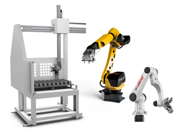
      • Automation Systems
      • Mill Automation
      • Lathe Automation
      • Automation Models
    • Haas Drill Centers Desktop Machines
      Desktop Machines
      Desktop Machines View All
      • Desktop Machines
      • Desktop Mill
      • Desktop Lathe
    • Haas Shop Equipment Shop Equipment
      Shop Equipment
      Shop Equipment View All
      • Shop Equipment
      • Bandsaw
      • Knee Mill
      • Surface Grinder, 2550
      • Surface Grinder, 3063
      • Laser Cutting Machine
    • QUICK LINKS Special Series  Special Series 
      EU SERIES EU SERIES BUILD & PRICE | PRICE LIST BUILD & PRICE | PRICE LIST In-Stock Machines In-Stock Machines WHAT’S NEW WHAT’S NEW YOUR FIRST CNC YOUR FIRST CNC
      SHOPPING TOOLS
      • Build & Price a Haas
      • Price List
      • Available Inventory
      • CNCA Financing
      WANT TO TALK TO SOMEONE?

      A Haas Factory Outlet (HFO) can answer your questions, and walk you through your best options.

      CONTACT YOUR DISTRIBUTOR >
  • Options Main Menu
    • Product Image Spindles
      Spindles
      Spindles View All
      • Spindles
    • Product Image Tool Changers
      Tool Changers
      Tool Changers View All
      • Tool Changers
    • Product Image 4th- | 5th-Axis
      4th- | 5th-Axis
      4th- | 5th-Axis View All
      • 4th- | 5th-Axis
    • Product Image Turrets & Live Tooling
      Turrets & Live Tooling
      Turrets & Live Tooling View All
      • Turrets & Live Tooling
    • Product Image Probing
      Probing
      Probing View All
      • Probing
    • Haas Chip & Coolant Management Chip & Coolant Management
      Chip & Coolant Management
      Chip & Coolant Management View All
      • Chip & Coolant Management
    • The Haas Control The Haas Control
      The Haas Control
      The Haas Control View All
      • The Haas Control
    • Product Image Product Options
      Product Options
      Product Options View All
      • Product Options
    • Product Image Tooling & Fixturing
      Tooling & Fixturing
      Tooling & Fixturing View All
      • Tooling & Fixturing
    • Product Image Workholding
      Workholding
      Workholding View All
      • Workholding
    • Product Image 5-Axis Solutions
      5-Axis Solutions
      5-Axis Solutions View All
      • 5-Axis Solutions
      • 5 Easy Steps to 5-Axis
    • QUICK LINKS Special Series  Special Series 
      EU SERIES EU SERIES BUILD & PRICE | PRICE LIST BUILD & PRICE | PRICE LIST In-Stock Machines In-Stock Machines WHAT’S NEW WHAT’S NEW YOUR FIRST CNC YOUR FIRST CNC
      SHOPPING TOOLS
      • Build & Price a Haas
      • Price List
      • Available Inventory
      • CNCA Financing
      WANT TO TALK TO SOMEONE?

      A Haas Factory Outlet (HFO) can answer your questions, and walk you through your best options.

      CONTACT YOUR DISTRIBUTOR >
  • Why Haas Main Menu
      Discover the Haas Difference
    • Why Haas
    • MyHaas
    • Education Community
    • Industry 4.0
    • Haas Certification
    • Customer Testimonials
  • Service Main Menu
      Welcome to Haas Service
      SERVICE HOME Operator’s Manuals How-To Procedures Troubleshooting Guides Preventive Maintenance Haas Parts Haas Tooling Videos
  • Videos Main Menu
  • Main Menu
    • View All
    • View All
      • Fiber Laser
    • View All
    • View All
      • HTEC Curriculum Support
    • View All
      • Haas 10 kg Cobot Package
      • Cobot Kits
    • View All
    • View All
      • 4 - AUTOMATION SYSTEMS
      • Mill Toolholding
      • Carousel-V2
    • View All
    • View All
    • View All
      • VF-4SS
    • View All
    • QUICK LINKS Special Series  Special Series 
      EU SERIES EU SERIES BUILD & PRICE | PRICE LIST BUILD & PRICE | PRICE LIST In-Stock Machines In-Stock Machines WHAT’S NEW WHAT’S NEW YOUR FIRST CNC YOUR FIRST CNC
      SHOPPING TOOLS
      • Build & Price a Haas
      • Price List
      • Available Inventory
      • CNCA Financing
      WANT TO TALK TO SOMEONE?

      A Haas Factory Outlet (HFO) can answer your questions, and walk you through your best options.

      CONTACT YOUR DISTRIBUTOR >
  • Haas Tooling Main Menu
      Automation Accessories Shop Support Mill Toolholding Mill Cutting Tools Boring Systems Mill Workholding Lathe Toolholding Lathe Cutting Tools Lathe Workholding Package Kits ER Collets & Chucks Holemaking Threading Broaching Tombstones & Kits Manual Chucks For Milling Deburring & Abrasives Tool Presetter & Heat Shrinkers Storage & Handling Machine Maintenance Tooling Accessories Apparel & Accessories Measuring & Inspection Winner's Circle Winner's Circle Clearance Today's Hot Deals
    • Haas Tooling
    • Winner's Circle
      Winner's Circle Shop All
      • WINNERS_CIRCLE-1Y
    • Winner's Circle
      Winner's Circle Shop All
      • WC-1Y-EU
    • Today’s Hot Deals
      Today’s Hot Deals Shop All
      • Mill Toolholding
      • Mill Tooling
      • Measuring & Inspection
      • Boring Systems
      • Mill Workholding
      • Shell Mill Kits
      • Lathe Toolholding
      • Lathe Tooling
      • Lathe Workholding
      • ER Collets & Chucks
      • Holemaking
      • Threading
      • Broaching
      • Tool Storage
      • Apparel & Accessories
    • Clearance
      Clearance Shop All
    • Measuring & Inspection
      Measuring & Inspection Shop All
      • Probe Kits & Accessories
      • Edge & Center Finders
      • Comparative Measuring Gauges
      • Height Gauges
      • Calipers
      • Threaded Plug & Ring Gauges
      • Gauge Blocks
      • Pin Gauges
      • Drop Indicators
      • Dial Test Indicators
      • Bore Gauges
      • Indicator Accessories
      • V Blocks
      • Setup Blocks
      • Depth Measuring
      • Micrometers
      • Micrometer Accessories
      • Micrometer Kits
      • Bore Gauge Kits
      • Starter Kits
      • Indicator Kits
      • Caliper Kits
      • Toolholder Check Station
      • Height Setters
      • Coordinate Measuring Machines
    • Automation Accessories
      Automation Accessories Shop All
      • Cobot Kits
      • Cobot Kits
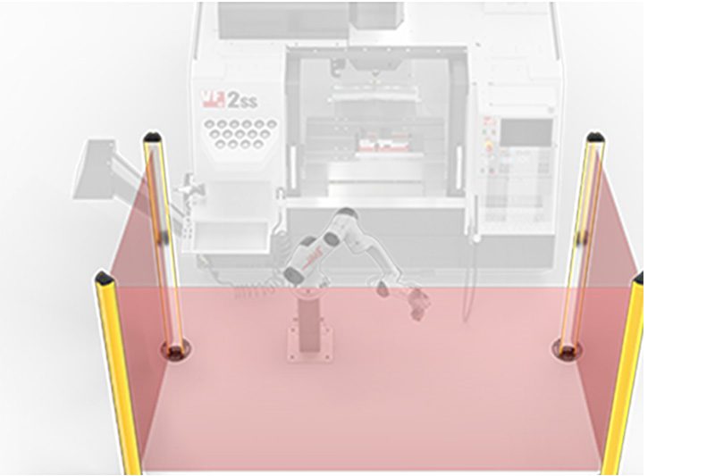
      • Protective Barriers
      • Grippers
      • Robot Cell Accessories
    • Shop Support
      Shop Support Shop All
      • Air Compressors
      • Laser Marking Machines
      • Bandsaw Blades
      • Bandsaw Accessories
      • Surface Grinding Wheels
      • Shop Equipment Accessories
    • Mill Toolholding
      Mill Toolholding Shop All
      • End Mill Holders
      • Shell Mill Holders
      • Shrink Fit Holders
      • ER Collet Chucks
      • Milling Chucks & Collets
      • NC Drilling Chucks
      • Pull Studs / Retention Knobs
      • Rotary Tool Holder & Tool Chuck Kits
      • Hydraulic Milling Chucks & Collets
      • Toolholder Attachments & Wrenches
      • Mill Broaching Holders
    • Mill Tooling
      Mill Tooling Shop All
      • Shell Mill Bodies
      • Milling Inserts
      • End Mills
      • Chamfer Mills & Inserts
      • Indexable End Mill Bodies
      • Ball End Mills
      • Chamfer End Mills
      • Roughing End Mills
      • Indexable Ball End Mills & Inserts
      • Shell Mill Kits
      • Chamfer Mill Kits
      • Indexable End Mill Kits
      • Dovetail Cutters
      • Indexable Dovetail Cutters
      • Engraving End Mills
      • Rotary Burrs / Die Grinding Bits
      • Keyseat Cutters
      • Corner Rounding End Mills
      • Slot Mill Bodies
      • CNC Router Bits For Wood
    • Boring Systems
      Boring Systems Shop All
      • Boring Heads & Cartridges
      • Boring Holders & Extensions
    • Mill Workholding
      Mill Workholding Shop All
      • Fixed-Jaw Vises
      • Self-Centering Vises
      • Adapter Plates
      • Vise Jaws
      • Vise Mounts & Fixtures
      • Vise Kits
      • Vise Parallels
      • Rotary Vise Kits
      • Fixture Clamps & Rails
      • Automated Workholding Kits
      • Tooling Fixture Subplates
      • Toolmakers' Vises
      • Clamp Force Gauges
      • Collet Fixtures
      • Angle Plates
    • Lathe Toolholding
      Lathe Toolholding Shop All
      • TL & CL Static Turning Holders
      • BOT Static Turning Holders
      • BMT Static Turning Holders
      • Live / Driven Turning Holders
      • Turning Holder Reduction Sleeves / Bushings
      • VDI Static Turning Holders
      • Turning Holder Accessories
    • Lathe Tooling
      Lathe Tooling Shop All
      • Cut-Off Tool Blocks & Blades
      • Cut-Off Tooling Kits
      • Turning Inserts
      • Grooving & Cut-Off Tools
      • Internal (ID) Grooving & Threading Tools
      • Threading Inserts
      • Threading Tools
      • Boring Bars / Internal (ID) Turning Tools
      • External (OD) Turning Tools
      • Cermet Turning Inserts
      • CBN Turning Inserts
      • Haas Notch Grooving & Threading Inserts
      • Haas Notch Grooving & Threading Tools
      • Micro Turning Tools
      • Desktop Lathe Tools
    • Lathe Workholding
      Lathe Workholding Shop All
      • Live Centers
      • Spindle Reduction Sleeves / Liners
      • Quick-Change Collets
      • Quick-Change Collet Chucks
      • 5C Collets
      • 5C Collet Sets
      • Lathe Jaw Boring Rings
      • Lathe Jaws
      • Bar Pullers
      • Scroll Chucks
      • Guide Pins
      • Collet Accessories
    • Package Kits
      Package Kits Shop All
      • Chip Clearing Fan Kits
      • Cutting Tool Kits
      • Indexable End Mill Kits
      • Cut-Off Tool Block & Blade Kits
      • Drill & Tap Kits
      • Indexable Drilling Kits
      • Shell Mill Kits
      • Chamfer Mill Kits
      • Rotary Tool Holder & Tool Chuck Kits
      • Lathe Starter Kits
      • Workholding Kits
      • Rotary Vise Kits
      • Vise Kits
      • 3-Jaw Chuck Kits for Mills
      • Tombstone Kits
      • Reduction Sleeve Kits
      • Automated Workholding Kits
      • Measuring & Inspection Kits
      • Starter Kits
      • Bore Gauge Kits
      • Caliper Kits
      • Indicator Kits
      • Micrometer Kits
    • ER Collets & Chucks
      ER Collets & Chucks Shop All
      • ER Straight-Bore Collets
      • ER Sealed Collets
      • ER Tap Collets
      • ER Collet Sets & Accessories
      • ER Collet Chucks
      • Straight Shank ER Collet Chucks
      • Straight Shank Keyless NC Drilling Chucks
    • Holemaking
      Holemaking Shop All
      • Carbide Drills
      • Indexable Drill Bodies
      • Indexable Drill Inserts
      • Modular Drill Bodies
      • Modular Drill Heads
      • Cobalt Drills & Sets
      • Center Drills
      • Reamers
      • Indexable Drilling Kits
      • Spot Drills
      • Spade Drill Bodies
      • Spade Drill Inserts
      • Countersinks
    • Threading
      Threading Shop All
      • Taps
      • Threading Inserts
      • Threading Tools
      • Thread Mills
      • Pipe Taps
      • Drill Tap Kits
    • Broaching
      Broaching Shop All
      • Broaching Tools
      • Broaching Inserts
    • Tombstones
      Tombstones Shop All
      • Tombstones
      • Tombstone Kits
      • Vise Cluster Towers
    • Manual Chucks For Milling
      Manual Chucks For Milling Shop All
      • 3-Jaw Chucks & Mounts for Mills
    • Deburring & Abrasives
      Deburring & Abrasives Shop All
      • Abrasive Pads
      • Deburr Tools
      • Deburr Wheels
      • Abrasive Sheets & Rolls
      • Sharpening / Lapping Stones
    • Tool Presetter & Heat Shrinkers
      Tool Presetter & Heat Shrinkers Shop All
      • Tool Presetting Machines
      • Shrink Fit Machines
    • Tool Storage
      Tool Storage Shop All
      • Tool Carts
      • Tool Tray
      • Tool Bags
    • Machine Maintenance
      Machine Maintenance Shop All
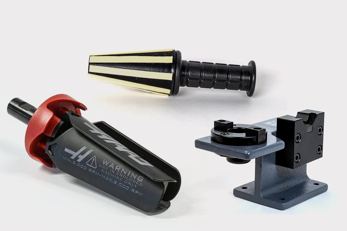
      • Spindle Test Bars
      • Levels
      • Refractometers
      • Machine Additives & Supplies
      • Machine Accessories
      • Machine Maintenance Kits
    • Tooling Accessories
      Tooling Accessories Shop All
      • Spindle & Toolholder Taper Cleaners
      • Haas Shop Lift
      • Toolholder Fixtures
      • CNC Chip Clearing Fans
      • Hammers & Mallets
      • Anti-Fatigue Mats
      • Layout Tools
      • Wrenches
      • Magnetic Tools
      • Torque Screwdrivers
      • Hand Cutting Tools
      • Shop Stools
      • Lifting Magnets
      • Safety Apparel
      • Cutting Tool Sharpeners
    • Apparel & Accessories
      Apparel & Accessories Shop All
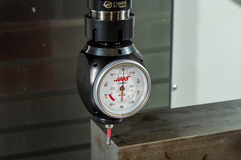
      • Accessories
      • Apparel
    • HAAS TOOLING QUICK LINKS
      NEW PRODUCTS NEW PRODUCTS NEW PRODUCTS NEW PRODUCTS
      MOST POPULAR MOST POPULAR
      TOOLING PROMOS TOOLING PROMOS
      FINANCING & OPEN TERMS FINANCING & OPEN TERMS PAY BY INVOICE PAY BY INVOICE
      FAQs FAQs
      KITS CREATED FOR YOU KITS CREATED FOR YOU
  • Haas Service Parts Main Menu
      Automatic Pallet Changer Lathe Turret Tool Changer Chip Management Coolant Counterbalance Electrical Cabinet Enclosure Hydraulics Lubrication Maintenance Pendant Probing Rotary Spindle Tailstock
    • Haas Service Parts
    • Automatic Pallet Changer
      Automatic Pallet Changer Shop All
      • HMC - Automatic Pallet Changer
      • VMC - Automatic Pallet Changer
    • Lathe Turret
      Lathe Turret Shop All
      • Lathe - Turret
      • Live Tooling
    • Tool Changer
      Tool Changer Shop All
      • Side Mount
      • Umbrella
    • Chip Management
      Chip Management Shop All
      • Multi Auger
      • Single Auger
    • Coolant
      Coolant Shop All
      • Auxiliary Filter
      • HPC-300 (Lathe)
      • HPC-1000 (Lathe)
      • Oil Skimmer
      • Standard Coolant
      • TSC-300 (Mill)
      • TSC-1000 (Mill)
      • Coolant Refill
      • Loc-Line
    • Counterbalance
      Counterbalance Shop All
      • Charge & Discharge Hose
    • Electrical Cabinet
      Electrical Cabinet Shop All
      • Fans
      • Filters
      • Upgrade Kits
    • Enclosure
      Enclosure Shop All
      • Accessories
      • Air Nozzle
      • Decals
      • Door Bumpers
      • Lighting
      • Windows, Gaskets, & Weather Strip
      • Chip & Coolant Management
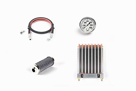
    • Hydraulics
      Hydraulics Shop All
      • Filters
      • Gauges
      • Heat Exchanger
      • Hoses
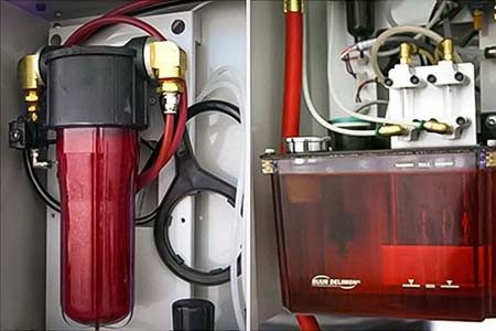
    • Lubrication
      Lubrication Shop All
      • Bijur Mechanical Lubrication
      • Minimum Lubrication
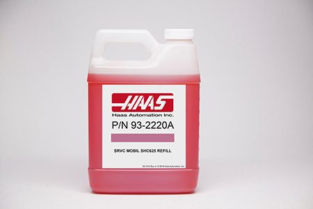
    • Maintenance
      Maintenance Shop All
      • Grease, Oil, & Sealants
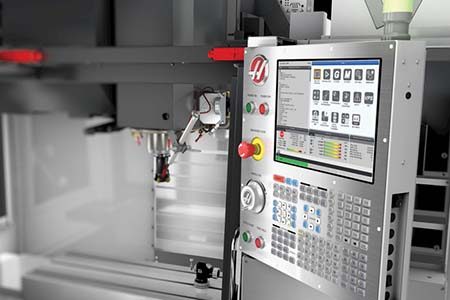
    • Pendant
      Pendant Shop All
      • Floppy Disk & USB
      • Keypad
      • Keys
      • Lens
      • Gaskets & Seals
    • Probing
      Probing Shop All
      • Mill Probing
      • Lathe Tool Presetter
    • Rotary
      Rotary Shop All
      • Rotary Gaskets & Seals
    • Spindles
      Spindles Shop All
      • Couplings
      • Gaskets & Seals
      • Spindle Motor Drive
      • Gearbox Drive
      • Tool Release Piston
    • Tailstock
      Tailstock Shop All
      • Handles
×

Search Results

Web Pages

Images

    • <
    • 1
    • >
MyHaas Welcome,
!
Haas Tooling Guest Order History MyHaas/HaasConnect Sign In Register Haas Tooling My Account Order History Return History MyHaas/HaasConnect Sign Out Welcome, My Machines Latest Activity My Quotes My Account My Users Sign Out
Find Your Distributor
  1. Select Language
    1. English
    2. Deutsch
    3. Español - España
    4. Español - México
    5. Français
    6. Italiano
    7. Português
    8. Český
    9. Dansk
    10. Nederlands
    11. Magyar
    12. Polski
    13. Svenska
    14. Türkçe
    15. 中文
    16. Suomi
    17. Norsk
    18. الإنجليزية
    19. български
    20. Hrvatski
    21. Ελληνικά
    22. Română
    23. Slovenský
    24. Slovenščina
    25. 한국어
    26. 日本語
    27. Українська
×

Search Results

Web Pages

Images

    • <
    • 1
    • >

12 - Lathe - Macros

Lathe Operator's Manual


  • 0 - Lathe - Table of Contents
  • 1 - Lathe - Introduction
  • 2 - Lathe - Legal Information
  • 3 - Lathe - Safety
  • 4 - Lathe - Control Pendant
  • 5 - Lathe - Control Display
  • 6 - Lathe - Device Manager
  • 7 - Lathe - TouchScreen Feature
  • 8 - Lathe - Part Setup
  • 9 - Lathe - Control Icons
  • 10 - Lathe - Operation
  • 11 - Lathe - Programming
  • 12 - Lathe - Macros
  • 13 - Lathe - Options Programming
  • 14 - Lathe - Probing
  • 15 - Lathe - Remote Jog Handle
  • 16 - Lathe - G-Codes
  • 17 - Lathe - M-Codes
  • 18 - Lathe - Settings
  • 19 - Lathe - Other Equipment

Go To :

  • 12.1 Introduction
  • 12.2 Macros Display
  • 12.3 Macro Arguments
  • 12.4 Macro Variables
  • 12.5 Macro Variables Table
  • 12.6 System Variables
  • 12.7 Macro Subprogram Call Option
  • 12.8 Aliasing

12.1 Introduction

Macros Introduction

NOTE: This control feature is optional; call your HFO for information on how to purchase it.

Macros add capabilities and flexibility to the control that are not possible with standard G-code. Some possible uses are: families of parts, custom canned cycles, complex motions, and driving optional devices. The possibilities are almost endless.

A Macro is any routine/subprogram that you can run multiple times. A macro statement can assign a value to a variable, read a value from a variable, evaluate an expression, conditionally or unconditionally branch to another point within a program, or conditionally repeat some section of a program.

Useful G and M Codes

M00, M01, M30 - Stop Program
G04 - Dwell
G65 Pxx - Macro subprogram call. Allows passing of variables.
M29 - Set output relay with M-FIN.
M129 - Set output relay with M-FIN.
M59 - Set output relay.
M69 - Clear output relay.
M96 Pxx Qxx - Conditional Local Branch when Discrete Input Signal is 0
M97 Pxx - Local Sub Routine Call
M98 Pxx - Sub Program Call
M99 - Sub Program Return or Loop
G103 - Block Lookahead Limit. No cutter comp allowed.
M109 - Interactive User Input

Round Off

The control stores decimal numbers as binary values. As a result, numbers stored in variables can be off by 1 least significant digit. For example, the number 7 stored in macro variable #10000, may later be read as 7.000001, 7.000000, or 6.999999. If your statement was

IF [#10000 EQ 7]… ;

it may give a false reading. A safer way of programming this would be

IF [ROUND [#10000] EQ 7]… ;

This issue is usually a problem only when you store integers in macro variables where you do not expect to see a fractional part later.

Look-ahead

Look-ahead is a very important concept in macro programming. The control attempts to process as many lines as possible ahead of time in order to speed up processing. This includes the interpretation of macro variables. For example,

#12012 = 1 ;
G04 P1. ;
#12012 = 0 ;

This is intended to turn an output on, wait 1 second, and then turn it off. However, lookahead causes the output to turn on then immediately back off while the control processes the dwell. G103 P1 is used to limit lookahead to 1 block. To make this example work properly, modify it as follows:

G103 P1 (See the G-code section of the manual for a further explanation of G103) ;
;
#12012=1 ;
G04 P1. ;
;
;
;
#12012=0 ;

Block Look-Ahead and Block Delete

The Haas control uses block look-ahead to read and prepare for blocks of code that come after the current block of code. This lets the control transition smoothly from one motion to the next. G103 limits how far ahead the control looks at blocks of code. The Pnnaddress code in G103 specifies how far ahead the control is allowed to look. For additional information, refer to G103 Limit Block Look-Ahead (Group 00)

Block Delete mode lets you selectively skip blocks of code. Use a / character at the beginning of the program blocks that you want to skip. Press BLOCK DELETE to enter the Block Delete mode. While Block Delete mode is active, the control does not execute the blocks marked with a / character. For example:

Using a

/M99 (Sub-Program Return) ;

before a block with

M30 (Program End and Rewind) ;

makes the sub-program a main program when BLOCK DELETE is on. The program is used as a sub-program when Block Delete is off.

When a block delete token "/" is used, even if Block Delete mode is not active, the line will block look ahead. This is useful for debugging macro processing within NC programs.

12.2 Macros Display

Macro Variable Display Page

You save or load macro variables through the Net Share or USB port, much like settings, and offsets.

The local and global macro variables #1 - #33 and #10000 - #10999 are displayed and modified through the Current Commands display.

NOTE: Internal to the machine, 10000 is added to 3-digit macro variables. For example: Macro 100 is displayed as 10100.

1

Press CURRENT COMMANDS and use navigation keys to get to the Macro Vars page.

As the control interprets a program, the variable changes and results are displayed on theMacro Vars display page.

Enter a value (maximum is 999999.000000) and then press ENTER to set the macro variable. Press ORIGIN to clear macro variables, this displays the Origin clear entry popup. Press number 1 - 3 to make a selection or press CANCEL to exit.

2

To search for a variable, enter the macro variable number and press the up or down arrow.

The variables displayed represent values of the variables when the program runs. At times, this may be up to 15 blocks ahead of actual machine actions. Debugging programs is easier when a G103 P1 is inserted at the beginning of a program to limit block buffering. A G103 without the P value can be added after the macro variable blocks in the program. For a macro program to operate correctly it is recommended that the G103 P1 be left in the program during loading of variables. For more details about G103 see the G-code section of the manual.

Display Macro Variables in the Timers And Counters Window

1

In the Timers And Counters window, you can display the values of any two macro variables and assign them a display name.

To set which two macro variables display in the Timers And Counters window:

2

Press CURRENT COMMANDS.

Use the navigation keys to select the TIMERS page.

Highlight the Macro Label #1 name or Macro Label #2 name.

Key in a new name, and press ENTER.

Use arrow keys to pick the Macro Assign #1 or Macro Assign #2 entry field (corresponding to your chosen Macro Label name).

Key in the macro variable number (without #) and press ENTER.

RESULTS:
On the Timers And Counters window, the field to the right of the entered Macro Label (#1 or #2) name displays the assigned variable value.

12.3 Macro Arguments

Macro Arguments

The arguments in a G65 statement are a means to send values to a macro subprogram and set the local variables of a macro subprogram.

The next (2) tables indicate the mapping of the alphabetic address variables to the numeric variables used in a macro subprogram.

Alphabetic Addressing

TABLE 1: Alphabetic Address Table

Address Variable   Address Variable
A 1   N -
B 2   O -
C 3   P -
D 7   Q 17
E 8   R 18
F 9   S 19
G -   T 20
H 11   U 21
I 4   V 22
J 5   W 23
K 6   X 24
L -   Y 25
M 13   Z 26

TABLE 2: Alternate Alphabetic Addressing

Address Variable   Address Variable   Address Variable
A 1   K 12   J 23
B 2   I 13   K 24
C 3   J 14   I 25
I 4   K 15   J 26
J 5   I 16   K 27
K 6   J 17   I 28
I 7   K 18   J 29
J 8   I 19   K 30
K 9   J 20   I 31
I 10   K 21   J 32
J 11   I 22   K 33

Arguments accept any floating-point value to four decimal places. If the control is in metric, it will assume thousandths (.000). In example below, local variable #1 will receive .0001. If a decimal is not included in an argument value, such as:

G65 P9910 A1 B2 C3 ;

The values are passed to macro subprograms according to this table:

Integer Argument Passing (no decimal point)

Address Variable   Address Variable   Address Variable
A .0001   J .0001   S 1.
B .0002   K .0001   T 1.
C .0003   L 1.   U .0001
D 1.   M 1.   V .0001
E 1.   N -   W .0001
F 1.   O -   X .0001
G -   P -   Y .0001
H 1.   Q .0001   Z .0001
I .0001   R .0001   - -

All 33 local macro variables can be assigned values with arguments by using the alternate addressing method. The following example shows how to send two sets of coordinate locations to a macro subprogram. Local variables #4 through #9 would be set to .0001 through .0006 respectively.

Example:

G65 P2000 I1 J2 K3 I4 J5 K6; 

The following letters cannot be used to pass parameters to a macro subprogram: G, L, N, O or P.

12.4 Macro Variables

Macro Variables

There are (3) categories of macro variables: local, global, and system.

Macro constants are floating-point values placed in a macro expression. They can be combined with addresses A-Z, or they can stand alone when used within an expression. Examples of constants are 0.0001, 5.3 or -10.

Local Variables

Local variables range between #1 and #33. A set of local variables is available at all times. When a call to a subprogram with a G65 command is executed, local variables are saved and a new set is available for use. This is called nesting of local variables. During a G65 call, all new local variables are cleared to undefined values and any local variables that have corresponding address variables in the G65 line are set to G65 line values. Below is a table of the local variables along with the address variable arguments that change them:

Variable: 1 2 3 4 5 6 7 8 9 10 11
Address: A B C I J K D E F - H
Alternate: - - - - - - I J K I J
Variable: 12 13 14 15 16 17 18 19 20 21 22
Address: - M - - - Q R S T U V
Alternate: K I J K I J K I J K I
Variable: 23 24 25 26 27 28 29 30 31 32 33
Address: W X Y Z - - - - - - -
Alternate: J K I J K I J K I J K

Variables 10, 12, 14- 16 and 27- 33 do not have corresponding address arguments. They can be set if a sufficient number of I, J and K arguments are used as indicated above in the section about arguments. Once in the macro subprogram, local variables can be read and modified by referencing variable numbers 1- 33.

When the L argument is used to do multiple repetitions of a macro subprogram, the arguments are set only on the first repetition. This means that if local variables 1- 33 are modified in the first repetition, then the next repetition will have access only to the modified values. Local values are retained from repetition to repetition when the L address is greater than 1.

Calling a subprogram via an M97 or M98 does not nest the local variables. Any local variables referenced in a subprogram called by an M98 are the same variables and values that existed prior to the M97 or M98 call.

Global Variables

Global variables are accessible at all times and remain in memory when power is turned off. There is only one copy of each global variable. Global variables are numbered #10000-#10999. Three legacy ranges: (#100-#199, #500-#699, and #800-#999) are included. The legacy 3 digit macro variables begin at the #10000 range; ie., macro variable #100 is displayed as #10100. 

NOTE: Using variable #100 or #10100 in a program the control will access the same data. Using either variable number is acceptable.

Sometimes, factory-installed options use global variables, for example, probing and pallet changers, etc. Refer to the Macro Variables Table for global variables and their use.

CAUTION: When you use a global variable, make sure that no other programs on the machine use the same global variable.

System Variables

System variables let you interact with a variety of control conditions. System variable values can change the function of the control. When a program reads a system variable, it can modify its behavior based on the value in the variable. Some system variables have a Read Only status; this means that you cannot modify them. Refer to the Macro Variables Table for a list of system variables and their use.

12.5 Macro Variables Table

Macro Variables Table

The macro variables table of local, global, and system variables and their usage follows. The new generation control variables list includes legacy variables.

NGC Variable Legacy Variable Usage
#0 #0 Not a number (read only)
#1- #33 #1- #33 Macro call arguments
#10000- #10199 #100- #199 General-purpose variables saved on power off
#10200- #10399 N/A General-purpose variables saved on power off
#10400- #10499 N/A General-purpose variables saved on power off
#10500- #10549 #500-#549 General-purpose variables saved on power off
#10550- #10580 #550-#580 Probe calibration data (if installed)
#10581- #10699 #581- #699 General-purpose variables saved on power off
#10700- #10799 #700- #749 Hidden variables for internal use only
#10709 #709 Used for the Fixture Clamp Input. Do not use for general purpose.
#10800- #10999 #800- #999 General-purpose variables saved on power off
#11000- #11063 N/A 64 discrete inputs (read only)
#1064- #1068 #1064- #1068 Maximum axis loads for X, Y, Z, A, and B Axes, respectively
#1080- #1087 #1080- #1087 Raw analog to digital inputs (read only)
#1090- #1098 #1090- #1098 Filtered analog to digital inputs (read only)
#1098 #1098 Spindle load with Haas vector drive (read only)
#1264- #1268 #1264- #1268 Maximum axis loads for C, U, V, W, and T-axes respectively
#1601- #1800 #1601- #1800 Number of flutes on tools #1 through 200
#1801- #2000 #1801- #2000 Maximum recorded vibrations of tools 1 through 200
#2001- #2050 #2001- #2050 X Axis tool shift offsets
#2051- #2100 #2051- #2100 Y Axis tool shift offsets
#2101- #2150 #2101- #2150 Z Axis tool shift offsets
#2201- #2250 #2201- #2250 Tool nose radius wear offsets
#2301- #2350 #2301- #2350 Tool tip direction
#2701- #2750 #2701- #2750 X Axis tool wear offsets
#2751- #2800 #2751- #2800 Y Axis tool wear offsets
#2801- #2850 #2801- #2850 Z Axis tool wear offsets
#2901- #2950 #2901- #2950 Tool nose radius wear offsets
#3000 #3000 Programmable alarm
#3001 #3001 Millisecond timer
#3002 #3002 Hour timer
#3003 #3003 Single block suppression
#3004 #3004 Override [FEED HOLD] control
#3006 #3006 Programmable stop with message
#3011 #3011 Year, month, day
#3012 #3012 Hour, minute, second
#3020 #3020 Power on timer (read only)
#3021 #3021 Cycle start timer
#3022 #3022 Feed timer
#3023 #3023 Present part timer (read only)
#3024 #3024 Last complete part timer
#3025 #3025 Previous part timer (read only)
#3026 #3026 Tool in spindle (read only)
#3027 #3027 Spindle RPM (read only)
#3030 #3030 Single block
#3032 #3032 Block delete
#3033 #3033 Opt stop
#3196 #3196 Cell safe timer
#3201- #3400 #3201- #3400 Actual diameter for tools 1 through 200
#3401- #3600 #3401- #3600 Programmable coolant positions for tools 1 through 200
#3901 #3901 M30 count 1
#3902 #3902 M30 count 2
#4001- #4099 #4001- #4099 Previous block G-code group codes
#4101- #4126 #4101- #4126 Previous block address codes. Note: (1) Mapping of 4101 to 4126 is the same as the alphabetic addressing of Macro Arguments section; e.g., the statement X1.3 sets variable #4124 to 1.3.
#4132 n/a Returns current active work offset number (including sub offset number if applicable)
#5001- #5006 #5001- #5006 Previous block end position
#5021- #5026 #5021- #5026 Present machine coordinate position
#5041- #5046 #5041- #5046 Present work coordinate position
#5061- #5069 #5061- #5069 Present skip signal position - X, Y, Z, A, B, C, U, V, W
#5081- #5086 #5081- #5086 Present tool offset
#5201- #5206 #5201- #5206 G52 work offsets
#5221- #5226 #5221- #5226 G54 work offsets
#5241- #5246 #5241- #5246 G55 work offsets
#5261- #5266 #5261- #5266 G56 work offsets
#5281- #5286 #5281- #5286 G57 work offsets
#5301- #5306 #5301- #5306 G58 work offsets
#5321- #5326 #5321- #5326 G59 work offsets
#5401- #5500 #5401- #5500 Tool feed timers (seconds)
#5501- #5600 #5501- #5600 Total tool timers (seconds)
#5601- #5699 #5601- #5699 Tool life monitor limit
#5701- #5800 #5701- #5800 Tool life monitor counter
#5801- #5900 #5801- #5900 Tool load monitor maximum load sensed so far
#5901- #6000 #5901- #6000 Tool load monitor limit
#6001- #6999 #6001- #6999 Reserved. Do not use.
#6198 #6198 NGC/CF flag
#7001- #7006 #7001- #7006 G110 (G154 P1) additional work offsets
#7021- #7026 #7021- #7026 G111 (G154 P2) additional work offsets
#7041- #7386 #7041- #7386 G112 - G129 (G154 P3 - P20)additional work offsets
#8500 #8500 Advanced Tool Management (ATM) group ID
#8501 #8501 ATM percent of available tool life of all tools in the group
#8502 #8502 ATM total available tool usage count in the group
#8503 #8503 ATM total available tool hole count in the group
#8504 #8504 ATM total available tool feed time (in seconds) in the group
#8505 #8505 ATM total available tool total time (in seconds) in the group
#8510 #8510 ATM next tool number to be used
#8511 #8511 ATM percent of available tool life of the next tool
#8512 #8512 ATM available usage count of the next tool
#8513 #8513 ATM available hole count of the next tool
#8514 #8514 ATM available feed time of the next tool (in seconds)
#8515 #8515 ATM available total time of the next tool (in seconds)
#8550 #8550 Individual tool ID
#8551 #8551 Number of flutes of tools
#8552 #8552 Maximum recorded vibrations
#8553 #8553 Tool length offsets
#8554 #8554 Tool length wear
#8555 #8555 Tool diameter offsets
#8556 #8556 Tool diameter wear
#8557 #8557 Actual diameter
#8558 #8558 Programmable coolant position
#8559 #8559 Tool feed timer (seconds)
#8560 #8560 Total tool timers (seconds)
#8561 #8561 Tool life monitor limit
#8562 #8562 Tool life monitor counter
#8563 #8563 Tool load monitor maximum load sensed so far
#8564 #8564 Tool load monitor limit
#9000 #9000 Thermal comp accumulator
#9000- #9015 #9000- #9015 Reserved (duplicate of axis thermal accumulator)
#9016-#9016 #9016-#9016 Thermal spindle comp accumulator
#9016- #9031 #9016- #9031 Reserved (duplicate of axis thermal accumulator from spindle)
#10000- #10999 N/A General purpose variables
#11000- #11255 N/A Discrete inputs (read only)
#12000- #12255 N/A Discrete outputs
#13000- #13063 N/A Filtered analog to digital inputs (read only)
#13013 N/A Coolant level
#14001- #14006 N/A G110(G154 P1) additional work offsets
#14021- #14026 N/A G110(G154 P2) additional work offsets
#14041- #14386 N/A G110(G154 P3- G154 P20) additional work offsets
#14401- #14406 N/A G110(G154 P21) additional work offsets
#14421- #15966 N/A G110(G154 P22- G154 P99) additional work offsets
#20000- #29999 N/A Setting
#30000- #39999 N/A Parameter
#32014 N/A Machine Serial Number
#50001- #50200 N/A Tool Type
#50201- #50400 N/A Tool material
#50401- #50600 N/A Tool Offset Point
#50601- #50800 N/A Estimated RPM
#50801- #51000 N/A Estimated Feedrate
#51001- #51200 N/A Offset Pitch
#51201- #51400 N/A Actually VPS Estimated RPM
#51401- #51600 N/A Work material
#51601- #51800 N/A VPS Feedrate
#51801- #52000 N/A X Approximate Probe Length
#52001- #52200 N/A Y Approximate Probe Length
#52201- #52400 N/A Z Approximate Probe Length
#52401- #52600 N/A Approximate Probe Diameter
#52601- #52800 N/A Edge Measure Height
#52801- #53000 N/A Tool Tolerance
#53201- #53400 N/A Probe Type
#53401- #53600 N/A Live Tool Radius
#53601- #53800 N/A Live Tool Radius Wear
#53801- #54000 N/A X Geometry
#54001- #54200 N/A Y Geometry
#54201- #54400 N/A Z Geometry
#54401- #54600 N/A Diameter Geometry
#54601- #54800 N/A Tip
#54801- #55000 N/A X Geometry Wear
#55001- #55200 N/A Y Geometry Wear
#55201- #55400 N/A Z Geometry Wear
#56701 - #56900 N/A Max Spindle Speed Per tool
#55401- #55600 N/A Diameter Wear
#62500 - #62509 N/A Spindle Speed (spindle 1,2,3)
#62510 - #62519 N/A Spindle Load (spindle 1,2,3)
#62520 - #62529 N/A Surface Speed (spindle 1,2,3)
#62530 - #62539 N/A Chip Load (spindle 1,2,3)
#62540- 62549 N/A Spindle Override (spindle 1,2,3)
#62590 N/A Feed Override
#62591 N/A Rapid Override
#62592 N/A Feed Rate
#62593 N/A Active Feed Rate
62742 N/A Safe Axes Load X
62743 N/A Safe Axes Load Y
62744 N/A Safe Axes Load Z
62745 N/A Safe Axes Load B
62746 N/A Active Tool
62747 N/A Rapid Override
62748 N/A Slow Rapid Override
62749 N/A Slow Rapid Distance
62750 N/A Completed Parts

12.6 System Variables

System Variables In-Depth

System variables are associated with specific functions. A detailed description of these functions follows.

#550-#699 #10550- #10699 General and Probe Calibration Data

These general purpose variables are saved on power off. Some of these higher #5xx variables store probe calibration data. Example: #592 sets which side of the table the tool probe is positioned. If these variables are overwritten, you will need to calibrate the probe again.

note: If the machine does not have a probe installed, you can use these variables as general-purpose variables saved on power off.

#1080-#1097 #11000-#11255 #13000-#13063 1-Bit Discrete Inputs

You can connect designated inputs from external devices with these macros:

Variables Legacy Variables Usage
#11000-#11255 - 256 discrete inputs (read only)
#13000-#13063 #1080-#1087
#1090-#1097
Raw and Filtered analog to digital inputs (read only)

Specific input values can be read from within a program. The format is #11nnn where nnn is the Input Number. Press DIAGNOSTIC and select the I/O tab to see the Input and Output numbers for different devices.

Example:

#10000=#11018

This example records the state of #11018, which refers to Input 18 (M-Fin_Input), to variable #10000.

For available User Inputs on the I/O PCB, refer to the Robot Integration Aid reference document in the Haas service website.

#12000-#12255 1-Bit Discrete Outputs

The Haas control is capable of controlling up to 256 discrete outputs. However, a number of these outputs are reserved for the Haas control to use.

Variables Legacy Variables Usage
#12000-#12255 - 256 discrete outputs

Specific output values can be read, or written to, from within a program. The format is #12nnn where nnn is the Output Number.

Example:

#10000=#12018 ;

This example records the state of #12018, which refers to Input 18 (Coolant Pump Motor), to variable #10000.

Maximum Axis Loads

These variables contain the maximum load an axis has achieved since the machine was last powered on, or since that Macro Variable was cleared. The Maximum Axis Load is the greatest load (100.0 = 100%) an axis has seen, not the Axis Load at the time that the control reads the variable.

#1064 = X Axis #1264 = C axis
#1065 = Y Axis #1265 = U axis
#1066 = Z Axis #1266 = V axis
#1067 = A Axis #1267 = W axis
#1068 = B Axis #1268 = T axis

Tool Offsets

Each tool offset has a length (H) and diameter (D) along with associated wear values.

#2001-#2200 H geometry offsets (1-200) for length.
#2201-#2400 H geometry wear (1-200) for length.
#2401-#2600 D geometry offsets (1-200) for diameter.
#2601-#2800 D geometry wear (1-200) for diameter.

#3000 Programmable Alarm Messages

#3000 Alarms can be programmed. A programmable alarm will act like the built-in alarms. An alarm is generated by setting macro variable #3000 to a number between 1 and 999.

#3000= 15 (MESSAGE PLACED INTO ALARM LIST) ;

When this is done, Alarm flashes at the bottom of the display and the text in the next comment is placed into the alarm list.
The alarm number (in this example, 15) is added to 1000 and used as an alarm number. If an alarm is generated in this manner all motion stops and the program must be reset to continue. Programmable alarms are always numbered between 1000 and 1999.

#3001-#3002 Timers

Two timers can be set to a value by assigning a number to the respective variable. A program can then read the variable and determine the time passed since the timer was set. Timers can be used to imitate dwell cycles, determine part-to-part time or wherever time-dependent behavior is desired.

  • #3001 Millisecond Timer - The millisecond timer represents the system time after power on in number of milliseconds. The whole number returned after accessing #3001 represents the number of milliseconds.
  • #3002 Hour Timer - The hour timer is similar to the millisecond timer except that the number returned after accessing#3002 is in hours. The hour and millisecond timers are independent of each other and can be set separately.

System Overrides

Variable #3003 overrides the Single Block function in G-code.

When #3003 has a value of 1, the control executes each G-code command continuously even though the Single Block function is ON.

When #3003 has a value of zero, Single Block operates as normal. You must press CYCLE START to execute each line of code in single block mode.

...
#3003=1 ;
G54 G00 G90 X0 Y0 ;
S2000 M03 ;
G43 H01 Z.1 ;
G81 R.1 Z-0.1 F20. ;
#3003=0 ;
T02 M06 ;
G43 H02 Z.1 ;
S1800 M03 ;
G83 R.1 Z-1. Q.25 F10. ;
X0. Y0. ;
%

Variable #3004

Variable #3004 overrides specific control features during operation.

The first bit disables FEED HOLD. If variable #3004 is set to 1, FEED HOLD is disabled for the program blocks that follow. Set #3004 to 0 to enable FEED HOLD again. For example:

..
(Approach code - FEED HOLD allowed) ;
#3004=1 (Disables FEED HOLD) ;
(Non-stoppable code - FEED HOLD not allowed) ;
#3004=0 (Enables FEED HOLD) ;
(Depart code - FEED HOLD allowed) ;
...

Variable #3004 resets to 0 at M30.
This is a map of variable #3004 bits and the associated overrides.

E = Enabled D = Disabled

#3004 Feed Hold Feed Rate Override Exact Stop Check
0 E E E
1 D E E
2 E D E
3 D D E
4 E E D
5 D E D
6 E D D
7 D D D

#3006 Programmable Stop

You can add stops to the program that act like an M00 - The control stops and waits until you press CYCLE START, then the program continues with the block after the #3006. In this example, the control displays the comment on the lower-center of the screen.

#3006=1 (comment here) ;

#3030 Single Block

In Next Generation Control when the system variable #3030 is set to a 1; the control will go into single block mode. There is no need to limit the lookahead using a G103 P1, the Next Generation Control will correctly process this code. 

NOTE: For the Classic Haas Control to process system variable #3030=1 correctly, it is necessary to limit the lookahead to 1 block using a G103 P1 before the #3030=1 code.

#4001-#4021 Last Block (Modal) Group Codes

G-code groups let the machine control process the codes more efficiently. G-codes with similar functions are usually in the same group. For example, G90 and G91 are under group 3. Macro variables #4001 through #4021 store the last or default G code for any of 21 groups.

G-Codes Group number is listed next to it's description in the G-Code section.

Example:

G81 Drill Canned Cycle (Group 09)

When a macro program reads the group code, the program can change the behavior of the G-code. If #4003 contains 91, then a macro program could determine that all moves should be incremental rather than absolute. There is no associated variable for group zero; group zero G codes are Non-modal.

#4101-#4126 Last Block (Modal) Address Data

Address codes A-Z (excluding G) are maintained as modal values. The information represented by the last line of code interpreted by the lookahead process is contained in variables #4101 through #4126.

The numeric mapping of variable numbers to alphabetic addresses corresponds to the mapping under alphabetic addresses. For example, the value of the previously interpreted D address is found in #4107 and the last interpreted I value is #4104. When aliasing a macro to an M-code, you may not pass variables to the macro using variables #1 - #33. Instead, use the values from #4101 - #4126 in the macro.

#5001-#5006 Last Target Position

The final programmed point for the last motion block can be accessed through variables #5001 - #5006, X, Z, Y, A, B, and C respectively. Values are given in the current work coordinate system and can be used while the machine is in motion.

#5021-#5026 Current Machine Coordinate Position

To get the current machine axis positions, call macro variables #5021-#5026 corresponding to axis X, Y, Z, A, B, and C, respectively.

#5021 X Axis #5022 Y Axis #5023 Z Axis
#5024 A Axis #5025 B Axis #5026 C Axis

NOTE: Values CANNOT be read while the machine is in motion.

#5041-#5046 Current Work Coordinate Position

To get the current work coordinate positions, call macro variables #5041-#5046 corresponding to axis X, Y, Z, A, B, and C, respectively.

NOTE: The values CANNOT be read while the machine is in motion.  The value of #504X has tool length compensation applied to it.

#5061-#5069 Current Skip Signal Position

Macro variables #5061-#5069 corresponding to X, Y, Z, A, B, C, U, V and W respectively, give the axis positions where the last skip signal occurred. Values are given in the current work coordinate system and can be used while the machine is in motion.

The value of #5063 (Z) has tool length compensation applied to it.

#5081-#5086 Tool Length Compensation

Macro variables #5081 - #5086 give the current total tool length compensation in axis X, Y, Z, A, B, or C, respectively. This includes tool length offset referenced by the current value set in H (#4008) plus the wear value.

#5201-#5326, #7001-#7386, #14001-#14386 Work Offsets

Macro expressions can read and set all work offsets. This lets you preset coordinates to exact locations, or set coordinates to values based upon the results of skip signal (probed) locations and calculations.

When any of the offsets are read, the interpretation look-ahead queue is stopped until that block is executed.

#6001-#6250 Settings Access with Macro Variables

Access settings through variables #20000 - #20999 or #6001 - #6250, starting from setting 1 respectively. Refer to Chapter 18 for the detailed descriptions of the settings that are available in the control.

NOTE: The #20000 - 20999 range numbers correspond directly to Setting numbers. You should use #6001 - #6250 for settings access only if you need your program to be compatible with older Haas machines

#6198 Next-Generation Control Identifier

The macro variable #6198 has a read-only value of 1000000.

You can test #6198 in a program to detect the control version, and then conditionally run program code for that control version. For example:

%
IF[#6198 EQ 1000000] GOTO5 ;
(Non-NGC code) ;
GOTO6 ;
N5 (NGC code) ;
N6 M30 ;
%

In this program, if the value stored in #6198 is equal to 1000000, go to Next Generation Control compatible code then end the program. If if the value stored in #6198 is not equal to 1000000, run the non-NGC program and then end the program.

#6996-#6999 Parameter Access With Macro Variables

These macro variables can access all parameters and any of the parameter bits, as follows:

  • #6996: Parameter Number
  • #6997: Bit Number (optional)
  • #6998: Contains the value of the parameter number specified in variable #6996
  • #6999: Contains the bit value (0 or 1) of the parameter bit specified in variable #6997.

NOTE: Variables #6998 and #6999 are read-only.

You can also use macro variables #30000 - #39999, starting from parameter 1, respectively. Contact your HFO for more details regarding parameter numbers.

USAGE: 

To access the value of a parameter, copy the number of that parameter into variable #6996. The value of that parameter is available in macro variable #6998, as shown:

%
#6996=601 (Specify parameter 601) ;
#10000=#6998 (Copy the value of parameter 601 to variable #10000) ;
%

To access a specific parameter bit, copy the parameter number into variable 6996 and the bit number to macro variable 6997. The value of that parameter bit is available in macro variable 6999, as shown:

%
#6996=57 (Specify parameter 57) ;
#6997=0 (Specify bit zero) ;
#10000=#6999 (Copy parameter 57 bit 0 to variable #10000) ;
%

Pallet Changer Variables

The status of the pallets from the Automatic Pallet Changer is checked with these variables:

#7501-#7506 Pallet priority
#7601-#7606 Pallet status
#7701-#7706 Part program numbers assigned to pallets
#7801-#7806 Pallet usage count
#3028 Number of pallet loaded on receiver

#8500-#8515 Advanced Tool Management

These variables give information on Advanced Tool Management (ATM). Set variable #8500 to the tool group number, then access information for the selected tool group with the read-only macros #8501-#8515.

#8500 Advanced Tool Management (ATM). Group ID
#8501 ATM. Percent of available tool life of all tools in the group.
#8502 ATM. Total available tool usage count in the group.
#8503 ATM. Total available tool hole count in the group.
#8504 ATM. Total available tool feed time (in seconds) in the group.
#8505 ATM. Total available tool total time (in seconds) in the group.
#8510 ATM. Next tool number to be used.
#8511 ATM. Percent of available tool life of the next tool.
#8512 ATM. Available usage count of the next tool.
#8513 ATM. Available hole count of the next tool.
#8514 ATM. Available feed time of the next tool (in seconds).
#8515 ATM. Available total time of the next tool (in seconds).

#8550-#8567 Advanced Tool Management Tooling

These variables give information on tooling. Set variable #8550 to the tool offset number, then access information for the selected tool with the read-only macros #8551-#8567

NOTE: Macro variables #1601-#2800 give access to the same data for individual tools as #8550-#8567 give for Tool Group tools.

#50001 - #50200 Tool Type

Use macro variables #50001 - #50200, to read or write the tool type set in the tool offset page.

Available Tool Types for Mill

Tool Type Tool Type#
Drill 1
Tap 2
Shell Mill 3
End Mill 4
Spot Drill 5
Ball Nose 6
Probe 7
Reserve for Future Use 8-20

12.7 Macro Subprogram Call Option

G65 Macro Subprogram Call Option

G65 is the command that calls a subprogram with the ability to pass arguments to it. The format follows:

G65 Pnnnnn [Lnnnn] [arguments] ;

Arguments italicized in square brackets are optional. See the Programming section for more details on macro arguments.

The G65 command requires a P address corresponding to a program number currently located in the control’s drive or path to a program. When the L address is used the macro call is repeated the specified number of times.

When a subprogram is called, the control looks for the subprogram on the active drive or the path to the program. If the subprogram cannot be located on the active drive, the control looks in the drive designated by Setting 251. Refer to the Setting Up Search Locations section for more information on subprogram searching. An alarm occurs if the control does not find the subprogram.

In Example 1, subprogram 1000 is called once without conditions passed to the subprogram. G65 calls are similar to, but not the same as, M98 calls. G65 calls can be nested up to 9 times, which means, program 1 can call program 2, program 2 can call program 3 and program 3 can call program 4.

Example 1:

G65 P1000 (Call subprogram O01000 as a macro) ;
M30 (Program stop) ;
O01000 (Macro Subprogram) ;

...

M99 (Return from Macro Subprogram) ;

In Example 2, the program LightHousing.nc is called using the path that it is in.

Example 2:

G65 P15 A1. B1.;
G65 (/Memory/LightHousing.nc) A1. B1.;


NOTE: Paths are case sensitive.

In Example 3, subprogram 9010 is designed to drill a sequence of holes along a line whose slope is determined by the X and Y arguments that are passed to it in the G65 command line. The Z drill depth is passed as Z, the feed rate is passed as F, and the number of holes to be drilled is passed as T. The line of holes is drilled starting from the current tool position when the macro subprogram is called.

Example 3:

NOTE: The subprogram program O09010 should reside on the active drive or on a drive designated by Setting 252.

G00 G90 X1.0 Y1.0 Z.05 S1000 M03 (Position tool) ;
G65 P9010 X.5 Y.25 Z.05 F10. T10 (Call O09010) ;
M30 ;

O09010 (Diagonal hole pattern) ;
F#9 (F=Feedrate) ;
WHILE [#20 GT 0] DO1 (Repeat T times) ;
G91 G81 Z#26 (Drill To Z depth) ;
#20=#20-1 (Decrement counter) ;
IF [#20 EQ 0] GOTO5 (All holes drilled) ;

G00 X#24 Y#25 (Move along slope) ;
N5 END1 ;
M99 (Return to caller) ;

12.8 Aliasing

Aliasing

Aliased codes are user defined G and M-codes that reference a macro program. There are 10 G alias codes and 10 M alias codes available to users. Program numbers 9010 through 9019 are reserved for G-code aliasing and 9000 through 9009 are reserved for M-code aliasing.

Aliasing is a means of assigning a G-code or M-code to a G65 P##### sequence. For instance, in the previous Example 2, it would be easier to write:

G06 X.5 Y.25 Z.05 F10. T10 ;

When aliasing, variables can be passed with a G-code; variables cannot be passed with an M-code.

Here, an unused G-code has been substituted, G06 for G65 P9010. In order for the previous block to work, the value associated with subprogram 9010 must be set to 06. Refer to the Setting Aliases section for how to setup aliases.

NOTE: G00, G65, G66, and G67 cannot be aliased. All other codes between 1 and 255 can be used for aliasing.

If a macro call subprogram is set to a G-code and the subprogram is not in memory, then an alarm is given. Refer to the G65 Macro Subprogram Call section on page 5 on how to locate the subprogram. An alarm occurs if the sub-program is not found.

If a macro call subprogram is set to a G-code and the subprogram is not in memory, then an alarm is given. Refer to the Macro Subprogram Call section on how to locate the subprogram. An alarm occurs if the sub-program is not found.

Feedback

Recently Viewed Items

You Have No Recently Viewed Items Yet

Feedback
Haas Logo

美元价格不包括关税、报关费用、保险费、增值税及运费。
USD prices DO NOT include customs duty, customs fees, insurance, VAT, or freight.

人民币价格包含关税、报关费用、货运保险和增值税, 但不包括运费。
CNY prices include customs duty, customs fees, insurance, and VAT. DOES NOT include freight.

Haas Delivered Price

This price includes shipping cost, export and import duties, insurance, and any other expenses incurred during shipping to a location in France agreed with you as a buyer. No other mandatory costs can be added to the delivery of a Haas CNC Product.

KEEP UP WITH THE LATEST HAAS TIPS AND TECHNOLOGY...

Sign up now!   

HAAS TOOLING ACCEPTS THE FOLLOWING:

  • Service & Support
  • Owners
  • Request Service
  • Operator Manuals
  • Haas Parts
  • Rotary Repair Request
  • Pre-Install Guides
  • Shopping Tools
  • Build & Price a New Haas
  • Available Inventory
  • The Haas Price List
  • CNCA Financing
  • About Haas
  • DNSH Statement
  • Careers
  • Certifications & Safety
  • Contact Us
  • History
  • Terms & Conditions
  • Haas Tooling Terms & Conditions
  • Privacy
  • Warranty
  • Haas Community
  • Haas Certification Program
  • Haas Motorsports
  • Gene Haas Foundation
  • Haas Technical Education Community
  • Events
  • Join the Conversation
  • Facebook
  • X
  • Flickr
  • YouTube
  • LinkedIn
  • Instagram
  • TikTok
© 2025 Haas Automation, Inc – CNC Machine Tools

This site is protected by reCAPTCHA and the Google Privacy Policy and Terms of Service apply.

2800 Sturgis Rd., Oxnard, CA 93030
Toll Free: (888) 817-4446 / Fax: 805-278-8554