My Haas Welcome,
!
Haas Tooling MyHaas/HaasConnect Sign In Register Haas Tooling MyHaas/HaasConnect Sign Out Welcome, My Machines Latest Activity My Quotes My Account My Users Sign Out
Find Your Distributor
  1. Select Language
    1. English
    2. Deutsch
    3. Español - ES
    4. Español - MX
    5. Français
    6. Italiano
    7. Português
    8. Český
    9. Dansk
    10. Nederlands
    11. Magyar
    12. Polski
    13. Svenska
    14. Türkçe
    15. 中文
    16. Suomi
    17. Norsk
    18. الإنجليزية
    19. български
    20. Hrvatski
    21. Ελληνικά
    22. Română
    23. Slovenský
    24. Slovenščina
    25. 한국어
    26. 日本語
    27. Українська
  • machines Main Menu
    • Vertical Mills
      Vertical Mills
      Vertical Mills View All
      • Vertical Mills
      • VF Series
      • Universal Machines
      • VR Series
      • VP-5 Prismatic
      • Pallet-Changing VMCs
      • Mini Mills
      • Mold Machines
      • High-Speed Drill Centers
      • Drill/Tap/ Mill Series
      • Toolroom Mills
      • Pocket Mill
      • Compact Mills
      • Gantry Series
      • SR Sheet Routers
      • Extra-Large VMC
      • Double-Column Mills
      • 3+2 Positioning Machines
    • Multi-Axis Solutions
      Multi-Axis Solutions
      Multi-Axis Solutions View All
      • Multi-Axis Solutions
      • Y-Axis Lathes
      • 5-Axis Mills
    • Lathes
      Lathes
      Lathes View All
      • Lathes
      • ST Series
      • Dual-Spindle
      • Box Way Series
      • Toolroom Lathes
      • Chucker Lathe
      • Pocket Lathe
      • Haas Bar Feeders
    • Horizontal Mills
      Horizontal Mills
      Horizontal Mills View All
      • Horizontal Mills
      • 50-Taper
      • 40-Taper
    • Rotaries & Indexers
      Rotaries & Indexers
      Rotaries & Indexers View All
      • Rotaries & Indexers
      • Rotary Tables
      • Indexers
      • 5-Axis Rotaries
      • Extra-Large Rotaries
    • Special Series
      Special Series
      Special Series View All
      • Special Series
      • EU_Series_Redirect
    • Automation Systems
      Automation Systems
      Automation Systems View All
      • Automation Systems
      • Mill Automation
      • Lathe Automation
      • Automatic Parts Loaders
      • Automation Models
    • Desktop Machines
      Desktop Machines
      Desktop Machines View All
      • Desktop Machines
      • Desktop Mill
      • Desktop Lathe
      • Control Simulator, Standard
      • Control Simulator, Premium
    • Shop Equipment
      Shop Equipment
      Shop Equipment View All
      • Shop Equipment
      • Knee Mill
      • Haas Manual Lathes
      • Haas Saws
    • Fabrication Machines
      Fabrication Machines
      Fabrication Machines View All
      • Fabrication Machines
      • Laser Cutting Machines
      • CNC Press Brakes
    • QUICK LINKS Special Series  Special Series 
      EU SERIES EU SERIES BUILD & PRICE | PRICE LIST BUILD & PRICE | PRICE LIST In-Stock Machines In-Stock Machines WHAT’S NEW WHAT’S NEW YOUR FIRST CNC YOUR FIRST CNC
      SHOPPING TOOLS
      • Build & Price a Haas
      • Price List
      • Available Inventory
      • CNCA Financing
      WANT TO TALK TO SOMEONE?

      A Haas Factory Outlet (HFO) can answer your questions, and walk you through your best options.

      CONTACT YOUR DISTRIBUTOR >
  • Options Main Menu
    • The Haas Control Value Option Packages
      Value Option Packages
      Value Option Packages View All
      • Value Option Packages
    • Product Image Spindles
      Spindles
      Spindles View All
      • Spindles
    • Product Image Tool Changers
      Tool Changers
      Tool Changers View All
      • Tool Changers
    • Product Image 4th- | 5th-Axis
      4th- | 5th-Axis
      4th- | 5th-Axis View All
      • 4th- | 5th-Axis
    • Product Image Turrets & Live Tooling
      Turrets & Live Tooling
      Turrets & Live Tooling View All
      • Turrets & Live Tooling
    • Product Image Probing
      Probing
      Probing View All
      • Probing
    • Haas Chip & Coolant Management Chip & Coolant Management
      Chip & Coolant Management
      Chip & Coolant Management View All
      • Chip & Coolant Management
    • The Haas Control The Haas Control
      The Haas Control
      The Haas Control View All
      • The Haas Control
    • Product Image Product Options
      Product Options
      Product Options View All
      • Product Options
    • Product Image Tooling & Fixturing
      Tooling & Fixturing
      Tooling & Fixturing View All
      • Tooling & Fixturing
    • Product Image Workholding
      Workholding
      Workholding View All
      • Workholding
    • Product Image 5-Axis Solutions
      5-Axis Solutions
      5-Axis Solutions View All
      • 5-Axis Solutions
      • 5 Easy Steps to 5-Axis
    • QUICK LINKS Special Series  Special Series 
      EU SERIES EU SERIES BUILD & PRICE | PRICE LIST BUILD & PRICE | PRICE LIST In-Stock Machines In-Stock Machines WHAT’S NEW WHAT’S NEW YOUR FIRST CNC YOUR FIRST CNC
      SHOPPING TOOLS
      • Build & Price a Haas
      • Price List
      • Available Inventory
      • CNCA Financing
      WANT TO TALK TO SOMEONE?

      A Haas Factory Outlet (HFO) can answer your questions, and walk you through your best options.

      CONTACT YOUR DISTRIBUTOR >
  • Why Haas Main Menu
      Discover the Haas Difference
    • Why Haas
    • MyHaas
    • Education Community
    • Industry 4.0
    • Haas Certification
    • Customer Testimonials
  • Service Main Menu
      Welcome to Haas Service
      SERVICE HOME Operator’s Manuals How-To Procedures Troubleshooting Guides Preventive Maintenance Haas Parts Haas Tooling Videos
  • Videos Main Menu
  • Main Menu
    • View All
    • View All
    • View All
    • View All
      • HTEC Curriculum Support
      • Haas Value Option Packages (VOP) Journey
    • View All
      • Haas 10 kg Cobot Package
      • Cobot Kits
      • DC-1 Drill Center
      • CNC Sales News
      • Do More With Your Haas
    • View All
    • View All
      • contact-us-test
      • 4 - AUTOMATION SYSTEMS
      • Carousel-V2
      • expert test
      • Demo_Day_Trident-test
      • Link Test
      • image-sale-tag-test
      • article-list-test
      • Haas 25 kg Robot Package
      • test-algolia-page
    • View All
    • View All
    • View All
    • View All
      • calc-test
    • View All
    • QUICK LINKS Special Series  Special Series 
      EU SERIES EU SERIES BUILD & PRICE | PRICE LIST BUILD & PRICE | PRICE LIST In-Stock Machines In-Stock Machines WHAT’S NEW WHAT’S NEW YOUR FIRST CNC YOUR FIRST CNC
      SHOPPING TOOLS
      • Build & Price a Haas
      • Price List
      • Available Inventory
      • CNCA Financing
      WANT TO TALK TO SOMEONE?

      A Haas Factory Outlet (HFO) can answer your questions, and walk you through your best options.

      CONTACT YOUR DISTRIBUTOR >
  • Haas Tooling Main Menu
  • Haas Service Parts Main Menu

My Haas Welcome,
!
Haas Tooling MyHaas/HaasConnect Sign In Register Haas Tooling MyHaas/HaasConnect Sign Out Welcome, My Machines Latest Activity My Quotes My Account My Users Sign Out
Find Your Distributor
  1. Select Language
    1. English
    2. Deutsch
    3. Español - ES
    4. Español - MX
    5. Français
    6. Italiano
    7. Português
    8. Český
    9. Dansk
    10. Nederlands
    11. Magyar
    12. Polski
    13. Svenska
    14. Türkçe
    15. 中文
    16. Suomi
    17. Norsk
    18. الإنجليزية
    19. български
    20. Hrvatski
    21. Ελληνικά
    22. Română
    23. Slovenský
    24. Slovenščina
    25. 한국어
    26. 日本語
    27. Українська
×

Search Results

Web Pages

Images

    • <
    • 1
    • >

20 - Coolant VFD

Chip Removal and Coolant - Service Manual


  • 1 - Chip and Coolant - Introduction
  • 2 - Auxiliary Coolant Filter
  • 3 - Single-Stage Flood Coolant
  • 4 - Oil Skimmer
  • 5 - Programmable Coolant
  • 6 - Chip Auger
  • 7 - Coolant Chiller
  • 8 - Chip Conveyor - Overview
  • 8a - Standard Belt Chip Conveyor
  • 8c - CDF Chip Conveyor
  • 9 - Chip Conveyor - VMC
  • 10 - Chip Conveyor - UMC
  • 11 - Chip Conveyor - Lathe
  • 12 - Coolant Refill
  • 13 - High Pressure Flood Coolant
  • 14 - Through-Spindle Coolant
  • 15 - Through-Tool Air Blast
  • 15a - Through-Tool Oil Mist
  • 16 - Haas Chip Lift
  • 17 - Mist Condenser
  • 18 - Coolant Level Float Sensor
  • 19 - Mini Conveyor
  • 20 - Coolant VFD
  • 21 - Coolant Sanitizer
  • 22 - Chip Separator
  • 23 - Chip Tray Strainer
  • 24 - Multi-Stage Flood Coolant
  • 25 - Coolant Cart

Go To :

  • 20.1 Coolant VFD - Overview
  • 20.2 Coolant VFD - Replacement
  • 20.3 Coolant VFD - Retrofit
  • 20.4 Coolant VFD - Troubleshooting
  • 20.5 DT/DM - VFD Coolant - Installation

20.1 Coolant VFD - Overview

Recently Updated

Coolant VFD - Overview


RD0018

Revision B - 09/2025

Coolant VFD - Introduction

This product is currently not field installable, documentation is for reference only. 

The Variable Flow Coolant Pump option uses a variable frequency drive (VFD) to control the speed of our standard centrifugal coolant pump during operation. This allows control of the coolant flow and pressure directly from the program, via M code and P values.

NOTE: Not compatible with the High-Pressure Flood Coolant option (HIGH PRESSURE COOL).

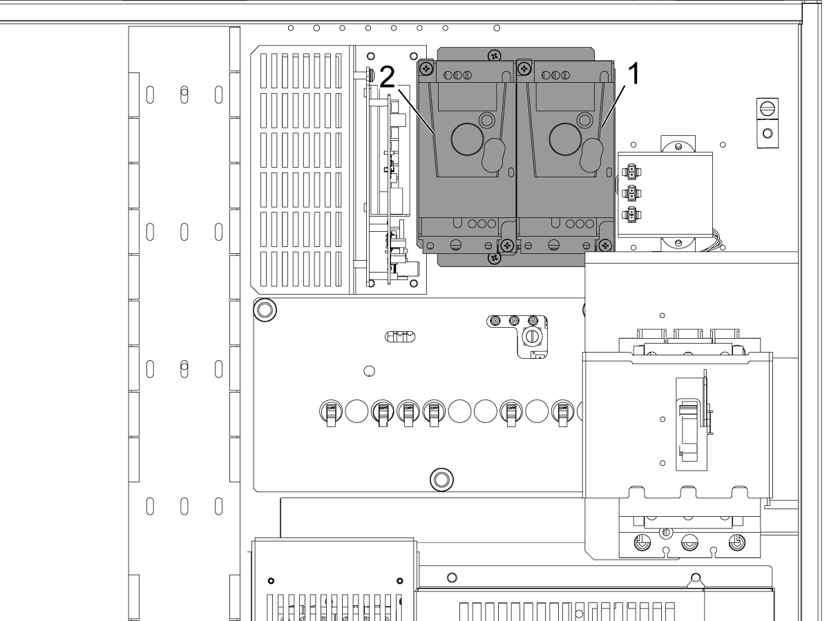
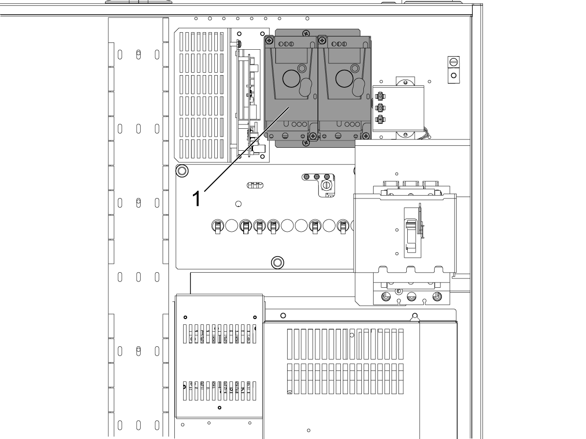
The illustration shows where the VFD is located in the electrical cabinet.
  1. Coolant Pump VFD
  2. Shower Pump VFD (on some models)

Coolant VFD - Operation

The variable flow coolant option allows the user to operate the coolant pump at different speeds to increase or decrease the flow of coolant.

An optional P-Code can be specified along with an M08 to change the speed of the coolant pump.

  • M08 P0 = Low Pressure - The pump will operate at 50HZ speed.
  • M08 P1 = Normal Pressure - The pump will operate at 60HZ speed.
  • M08 P2 = High Pressure - The pump will operate at 80HZ speed.

NOTE: If no P-Code is specified, or the specified P-Code is out of range, then normal pressure will be used.

NOTE: If the machine is not equipped with a Variable Frequency Drive for the coolant pump, then the P-Code will have no effect.

20.2 Coolant VFD - Replacement

Recently Updated

Coolant VFD - Replacement


AD0516

Introduction

This procedure will explain how to replace the VFD. 

The following procedure applies to:

  • 93-3501 SERVICE KIT FOR CLNT VFD 

For machines built before 2/9/2022 with VFD 69-0025. The machine must be upgraded with the following kits depending on the number of VFDs installed.

  • 93-3499 - SINGLE VFD RETROFIT KIT
  • 93-3498 - DUAL VFD RETROFIT KIT

Important: Do not use VFD Adapter PCB 34-3031A on machines with I/O PCB boards 34-3490C as the VFD adapter is built into this board version. 

 DANGER: Working with the electrical services required for CNC machines is extremely hazardous and can result in serious injury or death.

Before connecting line wires to the CNC:

  • Turn off all power to the machine at the source.
  • Perform a Lockout-Tagout (LOTO) procedure to ensure the power remains off during service.
  • Verify that power has been disconnected by using an AC voltage detector on all incoming lines.

If you are uncertain about how to safely disconnect power or perform LOTO procedures:

  • Do not proceed.
  • Contact qualified personnel or obtain appropriate assistance before continuing.

Failure to follow these precautions may result in electrical shock, equipment damage, or fatal injury.

 Danger: Before beginning any work inside the control cabinet, verify that the High Voltage indicator light on the 320V Power Supply / Vector Drive has been off for a minimum of five (5) minutes. This waiting period ensures that residual voltage has dissipated and reduces the risk of electric shock.

Certain service procedures involve high-risk electrical components and may pose serious injury or fatality hazards. Technicians must not attempt any procedure unless they have a complete understanding of the steps involved and the associated risks.

If there is any uncertainty regarding a procedure, contact your Haas Factory Outlet (HFO) to arrange for a qualified service technician.

Removal

1

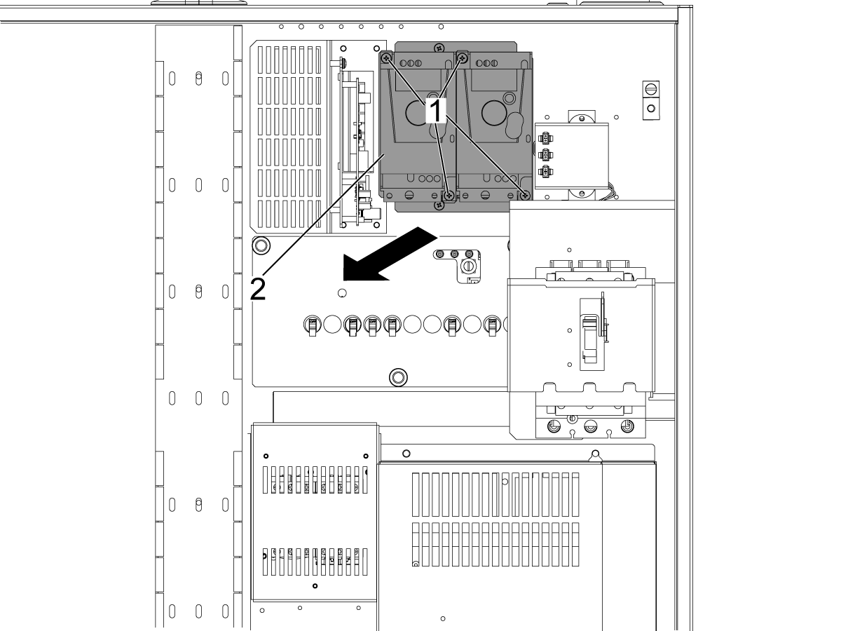
Remove the screws [1] holding VFD [2].

NOTE:  The SCHNEIDER brand is being shown on the illustration.

Installation

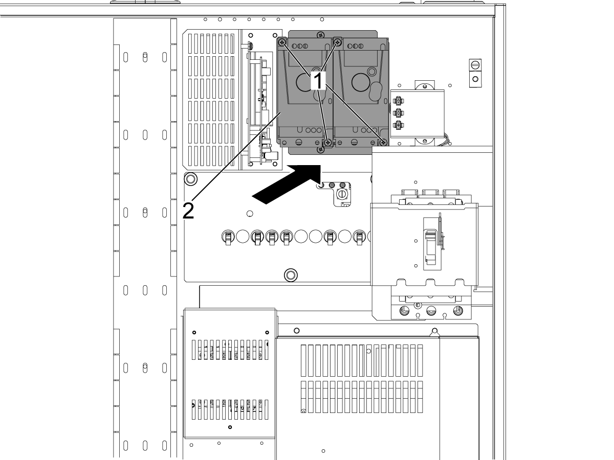
1

SCHNEIDER

Install the VFD the same way as the previous unit.

DELTA

Use the provided screws [1] to install the DELTA brand VFD where the previous VFD was placed.

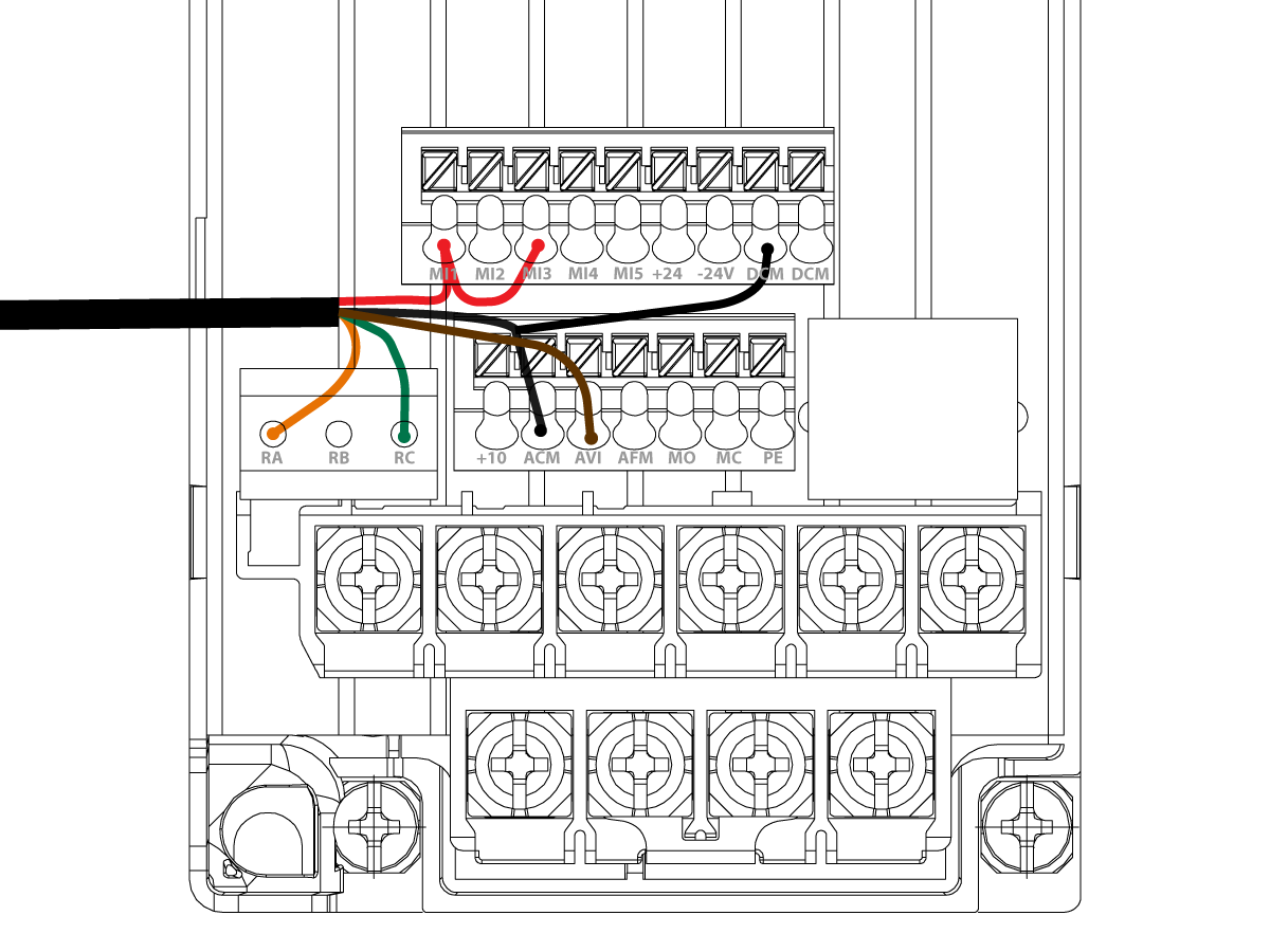
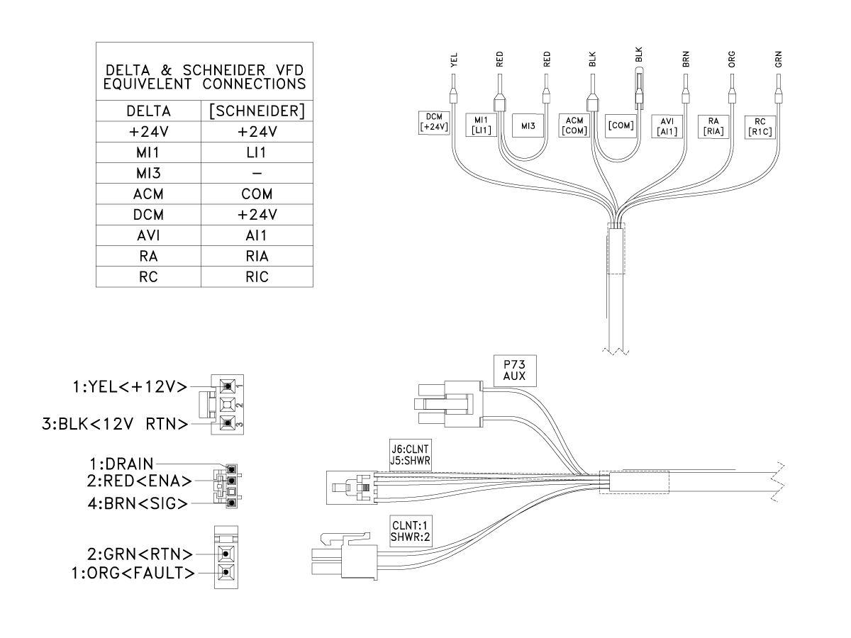
DELTA brand VFD wiring

1

When installing a DELTA brand VFD it should be wired as shown:

  • DCM - Black Wire Jumper
  • MI1 and MI3 - Red Wire and Red jumper wire.
  • ACM - Black Wire 
  • AVI - Brown Wire
  • RA - Orange Wire
  • RC - Green

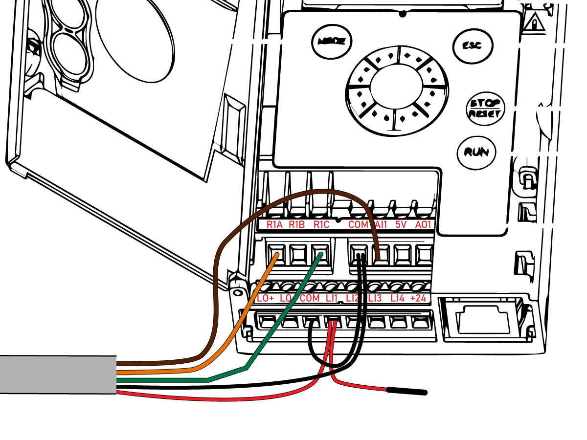
SCHNEIDER brand VFD wiring

1

When installing a SCHNEIDER brand VFD it should be wired as shown:

  • [LI1] - Red Wire

 NOTE: The Red jumper wire does not get connected, install electrical tape to the end. 

  • [COM] and [COM] - Black Wire and Black jumper wire.
  • [AI1] - Brown Wire
  • [RIA] - Orange Wire
  • [R1C] - Green


20.3 Coolant VFD - Retrofit

Recently Updated

Coolant VFD - Retrofit Kit


AD0602

Introduction

This procedure outlines how to install the new cables and adapter board to the I/O PCB and the VFD.

This procedure needs to be performed when replacing a VFD on a machine built before 2/9/2022 with VFD 69-0025. Refer to the Coolant VFD - Replacement procedure.

The machine must be upgraded with the following kits depending on the number of VFDs installed.

This procedure applies to the following service kit:

  • 93-3499: SINGLE VFD RETROFIT KIT
  • 93-3498: DUAL VFD RETROFIT KIT

Important: Do not use VFD Adapter PCB 34-3031A on machines with I/O PCB boards 34-3490C as the VFD adapter is built into this board version. 

Cable Replacement

1

Push [POWER OFF].

Set the main circuit breaker to the [OFF] position.

Lock the main circuit breaker. Use an approved lock with an approved safety tag.

Danger: After turning off the machine, wait at least 5 minutes before working in the control cabinet, to allow power to dissipate. Wait for the voltage indicator LED on the vector drive to go off completely.

2

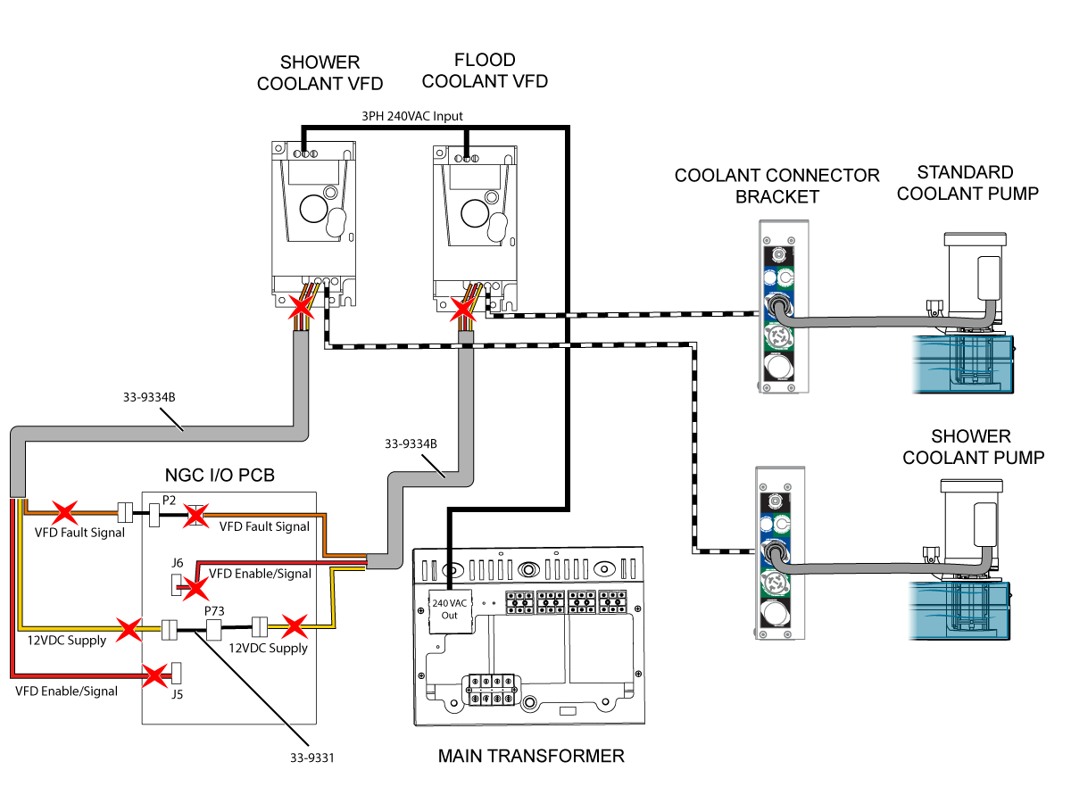
Remove cables 33-9331 and 33-9334B from the I/O PCB and the Coolant VFD and Shower Coolant VFD.

Note:  Not all machines are equipped with the Shower Coolant VFD.

3

Follow this step for Delta brand VFD's

On cable 33-9334C remove the vinyl cap from the red jumper wire labeled MI3. Then wire the cable to the VFD following the labels on the cable that are not in brackets. Refer to the image.

4

Follow this step for Schneider brand VFD's

Wire cable 33-9334C to the VFD by following the labels on the cable that are in brackets []. Refer to the image.

5

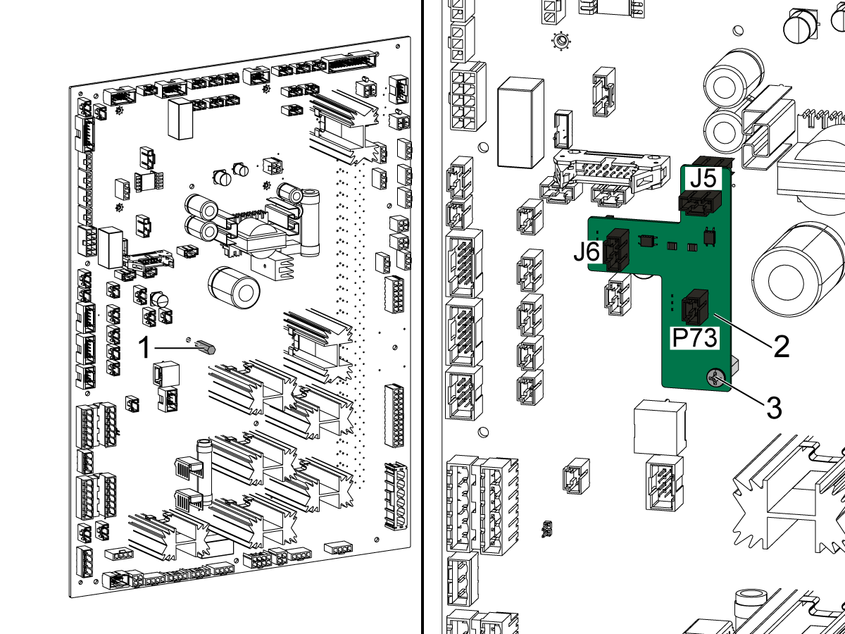
Follow this step for I/O PCB 34-348xA/B/C or 34-349xA/B

The I/O board will need to be removed so that the standoff [1] can be attached as shown on the left side of the image. The standoff [1] will need to be attached using the screw provided in the kit.

Note: A nylon standoff may need to be removed from the hole in the I/O board where the standoff will need to be installed.

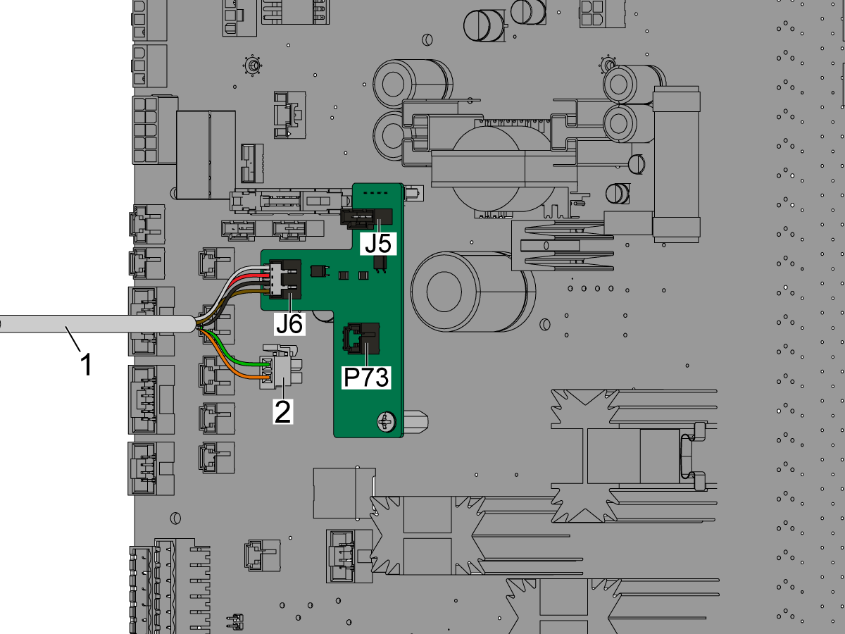
Attach the adapter board [2] to J5, J6, and P73 on the I/O board as shown on the right side of the image. Use the screw [3] provided in the kit to attach the adapter board [2] to the standoff.

Note: If there is a cable connected to P73 of the I/O board, disconnect it and connect it to P73 of the VFD adapter board.

6

Connect cable 33-9334C [1] to J6 on the VFD adapter PCB (34-3031A) for the flood coolant. Connect [2] to P2 on the I/O PCB.

If you also have a shower VFD, connect the second 33-9334C cable to J5 on the VFD adapter PCB (34-3031A).

NOTE: These connections are built into the new I/O PCB 34-349xC around the same location on the board. 

VFD Reprogramming

Warning: Do NOT reprogram the VFD before installing the new cables and adapter board, doing so can damage the IOPCB.

1

Follow this step for Delta brand VFD's

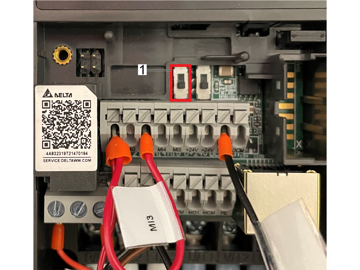
The 2 toggle switches above the wiring terminal need to be in the down position. [1]

Cycle machine power.

If the VFD has been programmed correctly, the red LED next to run should turn on when coolant is commanded on. 

2

Follow this step for Schneider brand VFD's

Note: The machine must be powered on when reprogramming the Schneider VFD.

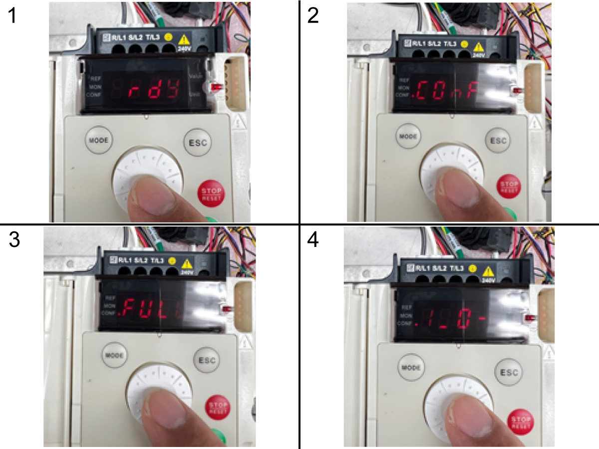
Press the selection wheel to enter the VFD menus. [1]

Rotate the selection wheel until the VFD display shows "ConF" and press the selection wheel to enter the menu. [2]

Rotate the selection wheel until the VFD display shows "FULL" and press the selection wheel to enter the menu. [3]

Rotate the selection wheel until the VFD display shows "I _ O -" and press the selection wheel to enter the menu. [4]

3

Follow this step for Schneider brand VFD's

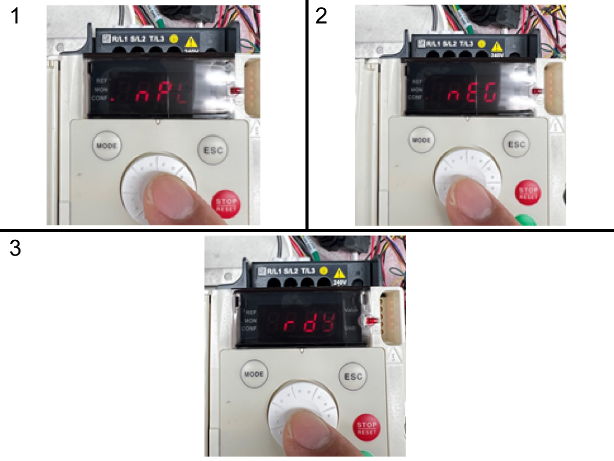
Rotate the selection wheel until the VFD display shows "nPL" and press the selection wheel to enter. [1]

An Un-programed VFD will display "EnEG". This needs to be changed to "nEG". Rotate the selection wheel until the display shows "nEG". [2]

When the display shows "nEG" press the selection wheel to save the configuration change.

VFD has now been programmed. Pres the "ESC" button on the VFD to exit all menus until the VFD displays "RDY". [3]

Cycle the power on the machine.

To exit a menu without saving the change, just press "ESC".

Troubleshooting

Symptom Probable Cause Corrective Action
The coolant still does not turn on when commanded after reprogramming the VFD. The VFD needs to be replaced. Order service kit 93-3501 for a reprogramed VFD and refer to the Coolant VFD Replacement procedure.

20.4 Coolant VFD - Troubleshooting

Recently Updated

Coolant VFD - Troubleshooting Guide - NGC


TG0056

Variable Frequency Drive (VFD) - Coolant Pumps

UMC's built after Nov 2019 and EC-1600's built after Jan 2020 now have a variable frequency drive (VFD) [1] units.  These VFD units are located on the control cabinet above the PSUP PCB, these units will drive the coolant pump and the shower coolant pump (if equipped).

A VFD is a Variable Frequency Drive. VFD’s run motors, and change their output frequency based on a command. This changes the speed of the motor. When used with coolant pump motors, coolant flow and pressure can be controlled, and not depend on the local line frequency of 50 or 60Hz. Some machines have up to two coolant pumps: standard and shower coolant; each is controlled by a separate VFD.

More troubleshooting information can be found on the manufacturer's user manual.

Schneider Altivar 12 User Manual
Delta ME300 Series User Manual

This feature allows you to select the desired pressure of the coolant pump.  

An optional P-Code can now be specified along with an M08. This P-Code can be used to specify the desired pressure level of the coolant pump:

P0 = Low Pressure
P1 = Normal Pressure
P2 = High Pressure

Note:  If no P-Code is specified, or the specified P-Code is out of range, then normal pressure will be used. 

Note: Specifying a P2 (High Pressure), the coolant pump will operate at louder sound level, this is normal.

The following parameters enable the VFD drive:

NOTE:  These parameters are set at the factory and listed here for reference only.

  • 2232 Coolant VDF Type 
  • 2233 Shower Coolant VFD Type

When set to 0 = no VFD and 1= VFD.

Symptom Table

Symptom Possible Cause Corrective Action
Machine with SCHENEIDER Variable Frequency Drive - The coolant takes too long to flow out the nozzles or Pcool. The variable frequency drive has an incorrect acceleration parameter value. Make sure the acceleration parameter on the variable frequency drive (VFD) is set to 0.3 seconds.  Refer to the VFD Acceleration Parameter Verification section below. 

Alarm 9823 Coolant VFD Fault

Alarm 9824 Shower Coolant VFD Fault

The coolant or shower pump is not plugged in. Make sure the coolant or shower pump is connected to the coolant port.  Check that the coolant cables are connected.
The variable frequency drive reported a fault. Open the control cabinet and see what fault was generated by the VFD.  Refer to the VFD Manual, see Variable Frequency Drive (VFD) section below.
The communication between the VFD unit and the control are not correct. See Variable Frequency Drive (VFD) section below.
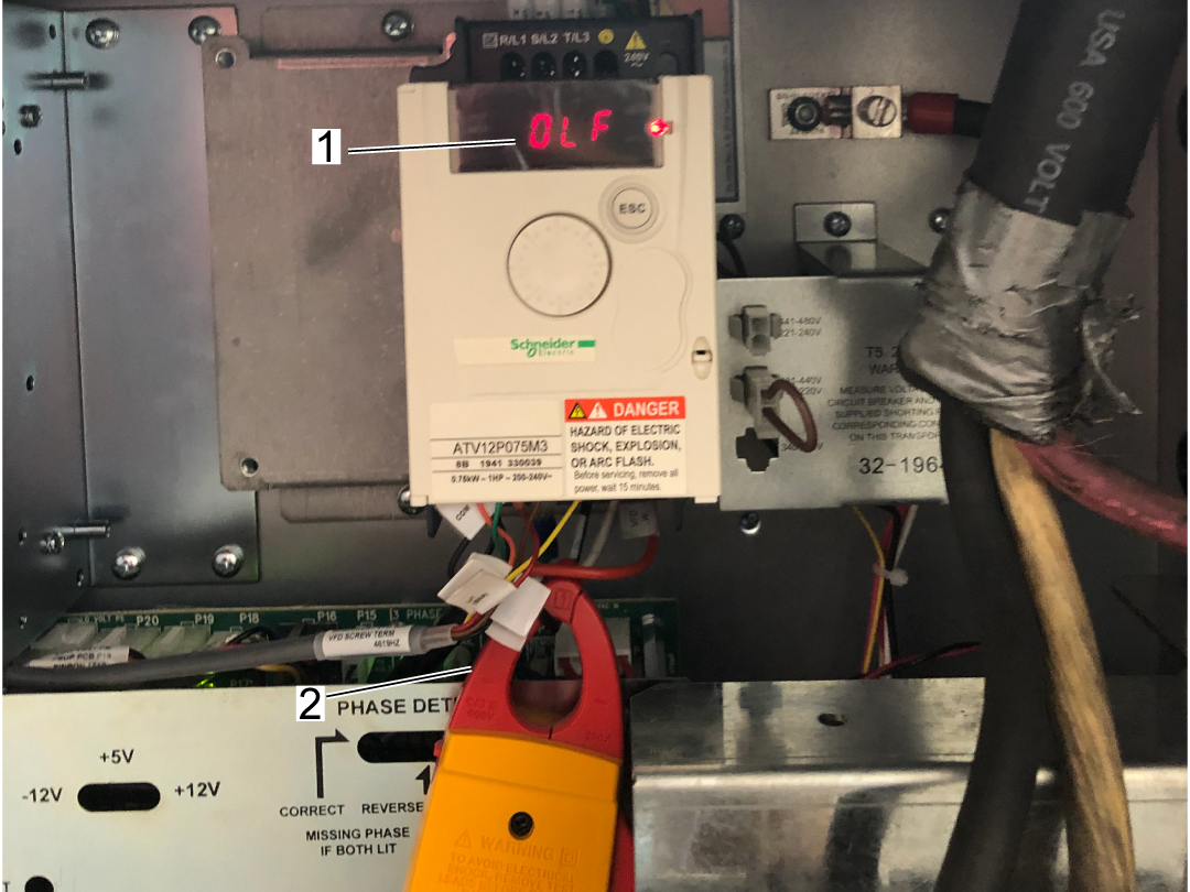
The VFD overloaded while running at the highest pressure setting P2 See Variable Frequency Drive (VFD) section below for VFD overload troubleshooting process. Contact Haas Service to notify them of this issue. 
Motor overload "OFL" alarm on the VFD while using the washdown nozzle.  Check the coolant tank level and make sure the pump is not cavitating, and verify the coolant tank is free of chips. 
The Coolant VFD is commanded to turn on (M08 PX), and the VFD shows "READY", and the pump does not turn on or takes several minutes to turn on.  The coolant VFD enable signal is not being read.  Determine if the drive has the Coolant VFD - Retrofit Kit Installed.  Refer to the Coolant VFD - Retrofit Kit - AD0602 procedure. 
Shortly after the replacement of a coolant VFD, intermittent alarm 9823 Coolant VFD Fault generated on Haas control, and error code "INF3" generated on the Schneider VFD. The machine is also built before 2/9/2022.  Incorrect VFD replacement kit used. 

Order and install the correct VFD replacement kit. 

Follow the instructions in AD0602 and AD0516.

For machines built before 2/9/2022 with VFD 69-0025. The machine must be upgraded with the following kits depending on the number of VFDs installed.

  • 93-3499 - SINGLE VFD RETROFIT KIT
  • 93-3498 - DUAL VFD RETROFIT KIT

Important: Do not use VFD Adapter PCB 34-3031A on machines with I/O PCB boards 34-3490C as the VFD adapter is built into this board version. 

VFD I/O Signals

The commands in a program cause an enable and speed command signal from the IOPCB to the VFD. Power for the VFD is supplied directly from the Main Transformer.

Use the below table to make sure the CNC control is sending and receiving the correct signals from the Coolant VFD unit.

Note: The value on the readout can be +/- 3Hz.

Command  Input / Output Diagnostics Bits Voltages at VFD
(Schneider)
Voltages at VFD
(Delta)
 VFD DISPLAY
M08 P0 INPUT 112 VFD_COOLANT_FAULT = 0

RIA / COM ≈ 0VDC RA / COM ≈ 0 VDC 49.9 Hz
OUTPUT 170 VFD_COOLANT_BIT_1 = 1

AI1 / COM ≈ 6.24 VDC AVI / COM ≈ 6.25 VDC
OUTPUT 171 VFD_COOLANT_BIT_2 = 0

OUTPUT 172 VFD_COOLANT_ENABLE = 1 LI1 / COM ≈ 0.3 VDC MI1 / COM ≈ 0.95 VDC
M08 P1 INPUT 112 VFD_COOLANT_FAULT = 0
RIA / COM ≈ 0 VDC RA / COM ≈ 0 VDC 59.9 Hz
OUTPUT 170 VFD_COOLANT_BIT_1 = 0
AI1 / COM ≈ 7.5 VDC AVI / COM ≈ 7.5 VDC
OUTPUT 171 VFD_COOLANT_BIT_2 = 1
OUTPUT 172 VFD_COOLANT_ENABLE = 1 LI1 / COM ≈ 0.3 VDC MI1 / COM ≈ 0.95 VDC
M08 P2 INPUT 112 VFD_COOLANT_FAULT = 0
RIA / COM ≈ 0VDC RA / COM ≈ 0 VDC 78.8 Hz
OUTPUT 170 VFD_COOLANT_BIT_1 = 1
AI1 / COM ≈ 9.9 VDC AVI / COM ≈ 9.9 VDC
OUTPUT 171 VFD_COOLANT_BIT_2 = 1
OUTPUT 172 VFD_COOLANT_ENABLE = 1 LI1 / COM ≈ 0.3 VDC MI1 / COM ≈ 0.95 VDC
Alarm  INPUT/OUTPUT DIAGNOSTIC BITS VOLTAGES AT VFD
(SCHNEIDER)
VOLTAGES AT VFD
(DELTA)
9823 COOLANT VFD FAULT  INPUT 112 VFD_COOLANT_FAULT = 1 RIA / COM ≈ 12 VDC RA / COM ≈ 12VDC
OUTPUT 170 VFD_COOLANT_BIT_1 = 0 AI1 / COM ≈ 0.0 VDC AVI / COM ≈ 0.16 VDC
OUTPUT 171 VFD_COOLANT_BIT_2 = 0
OUTPUT 172 VFD_COOLANT_ENABLE = 0 LI1 / COM ≈ 12 VDC MI1 / COM ≈ 12 VDC

VFD Acceleration Parameter Verification

The following procedure will show you how to make sure the acceleration parameter on the Schneider ATV12 VFD is set correctly. 

With the machine power on.  

WARNING: Becareful not to touch the incoming High Voltage Power wires.  If you don't feel comfortable with this procedure please contact your Haas Factory Outlet.

  1. Press the dial button one time
  2. Rotate the dial until you find CONF displayed on the screen.
  3. Press the dial button one time.
  4. Rotate the dial until you find ACC displayed on the screen.
  5. Press the dial button one time.
  6. Rotate the dial until the screen reads 0.3 
  7. Press the dial button one time.
  8. Press the ESC button until the screen reads RDY

VFD overload troubleshooting

1

The VFD will need to be tested at each of the pressure settings at each of the pressure settings make sure they are withing the range of the following.  

NOTE: The frequency can be seen where the overload alarm is shown [1]. Use a clamp meter [2] to record the current at the different settings.

 ~50 Hz at P0, test current at this setting and record

 ~60 Hz at P1, test current at this setting and record

 ~80 Hz at P2, test current at this setting and record. 

NOTE: Frequency should be within +/- 3Hz. If you are having overload issues contact Haas service.


Electrical Diagrams

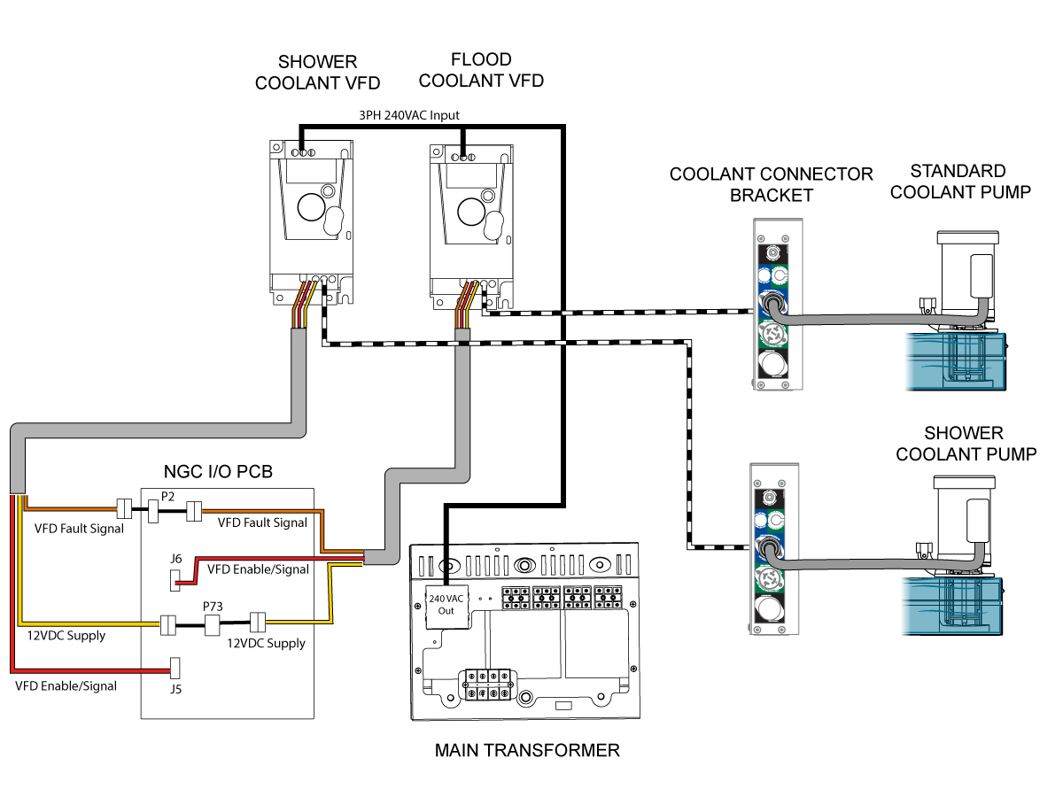
Use this electrical diagram for coolant pumps that are being driven by the Variable Frequency Drive With Cable 33-9934B.

33-9334B VFD Detail Cable Diagram

Use this electrical diagram for coolant pumps that are being driven by the Variable Frequency Drive With Cable 33-9334C.

33-9334C VFD Detail Cable Diagram

20.5 DT/DM - VFD Coolant - Installation

Recently Updated

DT/DM - VFD Coolant - Installation


AD0786

Introduction

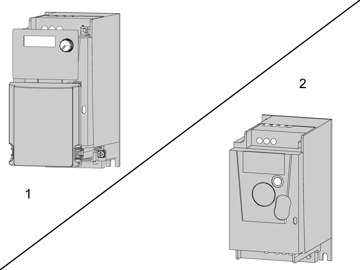
This procedure shows how to install the VFD Coolant option on DT/DM machines. There are 2 types of VFD units that can be installed. Both are the same in specification, the appearance is different:

  1. Delta VFD
  2. Scheider VFD

Machine Requirements:

  • 34-349XB - I/O PCB or Higher. 
  • DT-1/2 and DM-1/2 machines

Note: Use the VFD Adapter VPCB included in the kit for 34-349XB I/O PCB's. 34-349XC or higher does not requre the VFD Adapter PCB.

This procedure applies to the following kits:

  • 93-1001102 - Variable Flow Coolant DT/DM

Note: There are two different brands of variable frequency drives that could be included in these kits. Make sure to follow the procedure according to the correct type of VFD (either Delta brand or Schneider brand).

Steps in the procedure will be labeled for Shneider or Delta if applicable.

VFD Installation

 DANGER: Working with the electrical services required for CNC machines is extremely hazardous and can result in serious injury or death.

Before connecting line wires to the CNC:

  • Turn off all power to the machine at the source.
  • Perform a Lockout-Tagout (LOTO) procedure to ensure the power remains off during service.
  • Verify that power has been disconnected by using an AC voltage detector on all incoming lines.

If you are uncertain about how to safely disconnect power or perform LOTO procedures:

  • Do not proceed.
  • Contact qualified personnel or obtain appropriate assistance before continuing.

Failure to follow these precautions may result in electrical shock, equipment damage, or fatal injury.

 Danger: Before beginning any work inside the control cabinet, verify that the High Voltage indicator light on the 320V Power Supply / Vector Drive has been off for a minimum of five (5) minutes. This waiting period ensures that residual voltage has dissipated and reduces the risk of electric shock.

Certain service procedures involve high-risk electrical components and may pose serious injury or fatality hazards. Technicians must not attempt any procedure unless they have a complete understanding of the steps involved and the associated risks.

If there is any uncertainty regarding a procedure, contact your Haas Factory Outlet (HFO) to arrange for a qualified service technician.

1

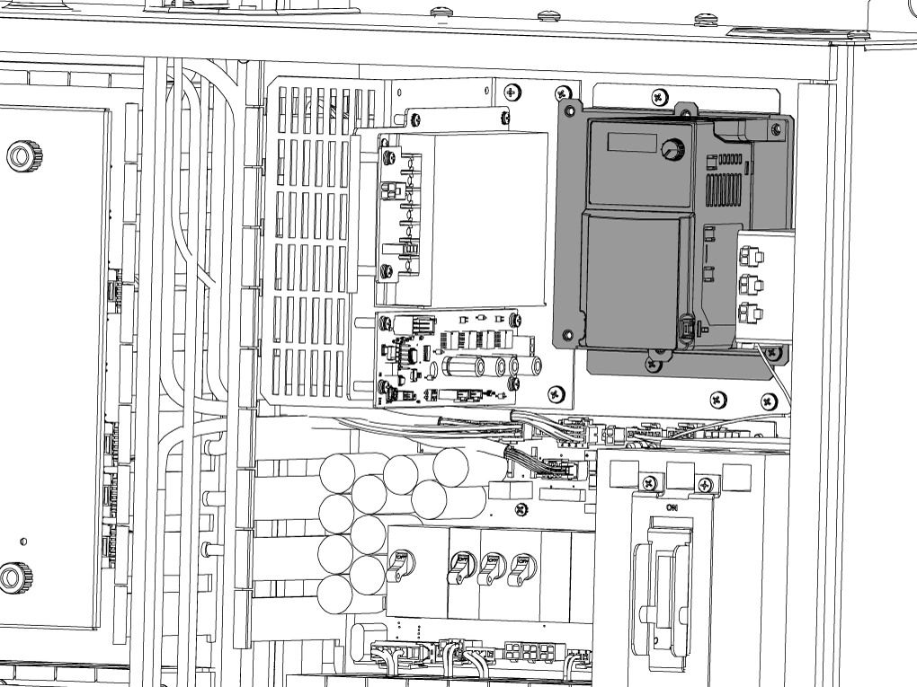
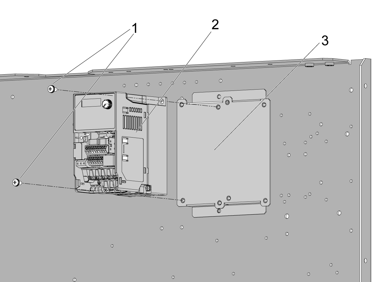
The VFD unit mounts in the control cabinet as shown in the image. The VFD should go by the breakers towards the top right corner of the control cabinet.

Use the 2 PPHS [1] to fasten the VFD unit [2] to the mounting plate [3].

2

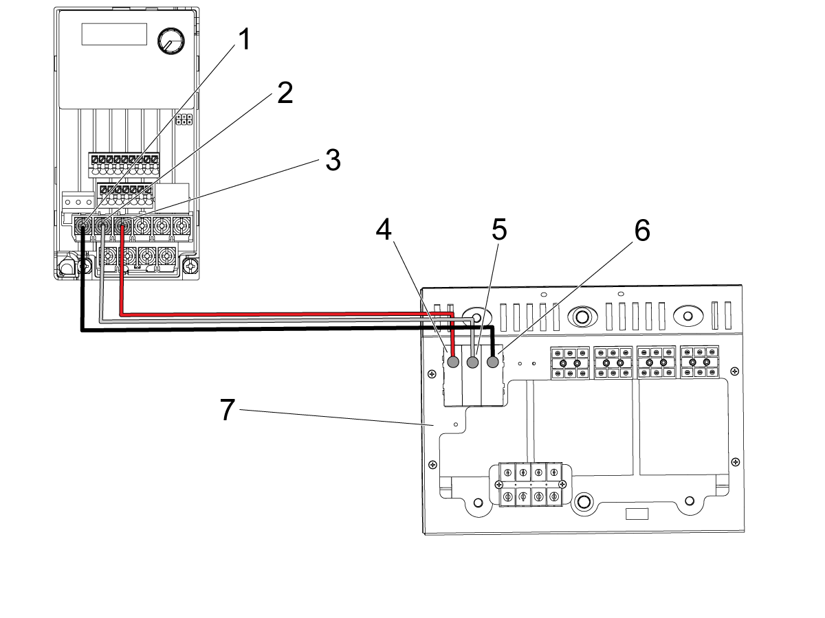
Connect the VFD unit to power comming from the transformer on the lower right side of the control cabinet.

Make the following connections with cable 33-1350 according to the labels.

On the VFD power side of the cable make the following connections at the TB2 [7] 240V out connector:

  1. Red to VFD T Terminal [1]
  2. White to VFD S Terminal [2]
  3. Black to VFD R Terminal [3]

On the Transformer side of the cable:

  1. Red to Transformer TB2, 77 Terminal [4]
  2. White to Transformer TB2, 78 Terminal [5]
  3. Black to Transformer TB2, 79 Terminal [6]

Note: This image shows the delta version VFD unit

3

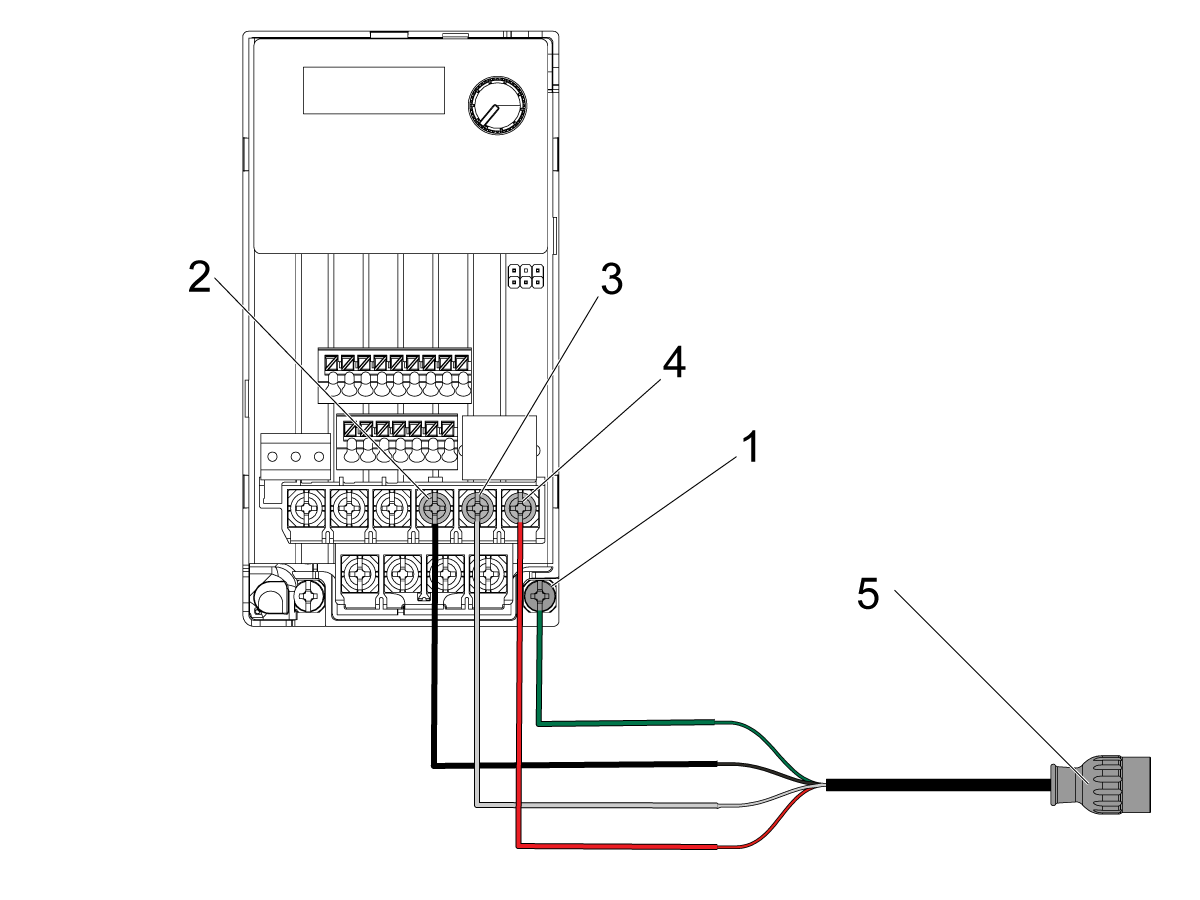
Connect the other end of the coolant pump power supply cable [5] 32-1242A to the labeled connections on the cables. 

The following connections should be made:

  1. Green Ground to VFD Ground [1]
  2. Black to VFD U Terminal [2]
  3. White to VFD V Terminal [3] 
  4. Red to VFD W Terminal [4]

Important: Use the ground cable 33-1358 to connect the VFD unit to one of the ground points on the back panel of the control cabinet.

Note: The connection points on the VFD are labeled on the terminals. Use the image as reference only.

4

Follow steps 4 and 5 for I/O PCB 34-349xA/B

The I/O board will need to be removed so that the standoff [1] can be attached as shown on the left side of the image. The standoff [1] will need to be attached using the screw provided in the kit.

Note: A nylon standoff may need to be removed from the hole in the I/O board where the standoff will need to be installed.

Attach the adapter board [2] to J5, J6, and P73 on the I/O board as shown on the right side of the image. Use the screw [3] provided in the kit to attach the adapter board [2] to the standoff.

Note: If there is a cable connected to P73 of the I/O board, disconnect it and connect it to P73 of the VFD adapter board.

Important: Do not use VFD Adapter PCB 34-3031A on machines with I/O PCB boards 34-3490C as the VFD adapter is built into this board version.

5

Connect cable 33-9334C [1] to J6 on the VFD adapter PCB (34-3031A) for the flood coolant. Connect [2] to P2 on the I/O PCB.

If you also have a shower VFD, connect the second 33-9334C cable to J5 on the VFD adapter PCB (34-3031A).

 NOTE: These connections are built into the new I/O PCB 34-349xC around the same location on the board. 

 Important: Do not use VFD Adapter PCB 34-3031A on machines with I/O PCB boards 34-3490C as the VFD adapter is built into this board version.

6

Follow this step for Schneider brand VFD's

 Note: For Delta VFD's, skip to the next step for wiring 33-9334C.

Wire cable 33-9334C to the VFD by following the labels on the cable that are in brackets []. Refer to the image.

Make the following connections:

  1. Red to LI1
  2. Red Jumper to NO CONNECTION MADE (only for Delta VFD units)
  3. Black to COM
  4. Black Jumper to COM (2 separate COM terminals)
  5. Brown to AI1
  6. Orange to RIA
  7. Green to R1C

7

Follow this step for Delta brand VFD's

On cable 33-9334C remove the vinyl cap from the red jumper wire labeled MI3. Then wire the cable to the VFD following the labels on the cable that are not in brackets. Refer to the image and make the following connections:

  1. Red to MI3
  2. Red Jumper to MI1
  3. Black to ACM
  4. Black Jumper to DCM
  5. Brown to AVI
  6. Orange to RA
  7. Green to RC

8

Place the 1HP coolant pump assembly [1] in the coolant tank cart [2] as shown in the image.

Install the power socket end of the VFD power outlet [3] (cable 32-1242A that was wired to the VFD in step 3) near the bottom of the control cabinet near the coolant tank.

Connect the power cable [4] from the coolant pump into the power outlet cable [3] 32-1242A.

VFD Coolant Testing

1

Test that the VFD coolant is operational.

An optional P-Code can be specified along with an M08 to change the speed of the coolant pump.

  • M08 P0 = Low Pressure - The pump will operate at 50HZ speed.
  • M08 P1 = Normal Pressure - The pump will operate at 60HZ speed.
  • M08 P2 = High Pressure - The pump will operate at 80HZ speed.

Verify that when running these commands the coolant pressure changes.

NOTE: If no P-Code is specified, or the specified P-Code is out of range, then normal pressure will be used.

For information on how to troubleshoot issues with the VFD unit refer to the VFD-troubleshooting guide.

Recently Viewed Items

You Have No Recently Viewed Items Yet

Feedback
Haas Logo

Haas Delivered Price

This price includes shipping cost, export and import duties, insurance, and any other expenses incurred during shipping to a location in France agreed with you as a buyer. No other mandatory costs can be added to the delivery of a Haas CNC Product.

KEEP UP WITH THE LATEST HAAS TIPS AND TECHNOLOGY...

Sign up now!   

HAAS TOOLING ACCEPTS THE FOLLOWING:

  • Service & Support
  • Owners
  • Request Service
  • Operator Manuals
  • Haas Parts
  • Rotary Repair Request
  • Pre-Install Guides
  • Shopping Tools
  • Build & Price a New Haas
  • Available Inventory
  • The Haas Price List
  • CNCA Financing
  • About Haas
  • Accessibility Statement
  • DNSH Statement
  • Export Compliance
  • Careers
  • Certifications & Safety
  • Contact Us
  • History
  • Terms & Conditions
  • Haas Tooling Terms & Conditions
  • Privacy
  • Warranty
  • Haas Community
  • Haas Certification Program
  • Haas Motorsports
  • Gene Haas Foundation
  • Haas Technical Education Community
  • Events
  • Join the Conversation
  • Facebook
  • X
  • Flickr
  • YouTube
  • LinkedIn
  • Instagram
  • TikTok
© 2026 Haas Automation, Inc – CNC Machine Tools

This site is protected by reCAPTCHA and the Google Privacy Policy and Terms of Service apply.

2800 Sturgis Rd., Oxnard, CA 93030
Toll Free: (888) 817-4446 / Fax: 805-278-8554