My Haas Welcome,
!
Haas Tooling MyHaas/HaasConnect Sign In Register Haas Tooling MyHaas/HaasConnect Sign Out Welcome, My Machines Latest Activity My Quotes My Account My Users Sign Out
Find Your Distributor
  1. Select Language
    1. English
    2. Deutsch
    3. Español - España
    4. Español - México
    5. Français
    6. Italiano
    7. Português
    8. Český
    9. Dansk
    10. Nederlands
    11. Magyar
    12. Polski
    13. Svenska
    14. Türkçe
    15. 中文
    16. Suomi
    17. Norsk
    18. الإنجليزية
    19. български
    20. Hrvatski
    21. Ελληνικά
    22. Română
    23. Slovenský
    24. Slovenščina
    25. 한국어
    26. 日本語
    27. Українська
  • machines Main Menu
    • Vertical Mills
      Vertical Mills
      Vertical Mills View All
      • Vertical Mills
      • VF Series
      • Universal Machines
      • VR Series
      • VP-5 Prismatic
      • Pallet-Changing VMCs
      • Mini Mills
      • Mold Machines
      • High-Speed Drill Centers
      • Drill/Tap/ Mill Series
      • Toolroom Mills
      • Pocket Mill
      • Compact Mills
      • Gantry Series
      • SR Sheet Routers
      • Extra-Large VMC
      • Double-Column Mills
      • 3+2 Positioning Machines
    • Multi-Axis Solutions
      Multi-Axis Solutions
      Multi-Axis Solutions View All
      • Multi-Axis Solutions
      • Y-Axis Lathes
      • 5-Axis Mills
    • Lathes
      Lathes
      Lathes View All
      • Lathes
      • ST Series
      • Dual-Spindle
      • Box Way Series
      • Toolroom Lathes
      • Chucker Lathe
      • Haas Bar Feeders
    • Horizontal Mills
      Horizontal Mills
      Horizontal Mills View All
      • Horizontal Mills
      • 50-Taper
      • 40-Taper
    • Rotaries & Indexers
      Rotaries & Indexers
      Rotaries & Indexers View All
      • Rotaries & Indexers
      • Rotary Tables
      • Indexers
      • 5-Axis Rotaries
      • Extra-Large Rotaries
    • Special Series
      Special Series
      Special Series View All
      • Special Series
      • EU_Series_Redirect
    • Automation Systems
      Automation Systems
      Automation Systems View All
      • Automation Systems
      • Mill Automation
      • Lathe Automation
      • Automatic Parts Loaders
      • Automation Models
    • Desktop Machines
      Desktop Machines
      Desktop Machines View All
      • Desktop Machines
      • Desktop Mill
      • Desktop Lathe
      • Control Simulator, Standard
      • Control Simulator, Premium
    • Shop Equipment
      Shop Equipment
      Shop Equipment View All
      • Shop Equipment
      • Knee Mill
      • Haas Manual Lathes
      • Haas Saws
    • Fabrication Machines
      Fabrication Machines
      Fabrication Machines View All
      • Fabrication Machines
      • Laser Cutting Machines
      • CNC Press Brakes
    • QUICK LINKS Special Series  Special Series 
      EU SERIES EU SERIES BUILD & PRICE | PRICE LIST BUILD & PRICE | PRICE LIST In-Stock Machines In-Stock Machines WHAT’S NEW WHAT’S NEW YOUR FIRST CNC YOUR FIRST CNC
      SHOPPING TOOLS
      • Build & Price a Haas
      • Price List
      • Available Inventory
      • CNCA Financing
      WANT TO TALK TO SOMEONE?

      A Haas Factory Outlet (HFO) can answer your questions, and walk you through your best options.

      CONTACT YOUR DISTRIBUTOR >
  • Options Main Menu
    • The Haas Control Value Option Packages
      Value Option Packages
      Value Option Packages View All
      • Value Option Packages
    • Product Image Spindles
      Spindles
      Spindles View All
      • Spindles
    • Product Image Tool Changers
      Tool Changers
      Tool Changers View All
      • Tool Changers
    • Product Image 4th- | 5th-Axis
      4th- | 5th-Axis
      4th- | 5th-Axis View All
      • 4th- | 5th-Axis
    • Product Image Turrets & Live Tooling
      Turrets & Live Tooling
      Turrets & Live Tooling View All
      • Turrets & Live Tooling
    • Product Image Probing
      Probing
      Probing View All
      • Probing
    • Haas Chip & Coolant Management Chip & Coolant Management
      Chip & Coolant Management
      Chip & Coolant Management View All
      • Chip & Coolant Management
    • The Haas Control The Haas Control
      The Haas Control
      The Haas Control View All
      • The Haas Control
    • Product Image Product Options
      Product Options
      Product Options View All
      • Product Options
    • Product Image Tooling & Fixturing
      Tooling & Fixturing
      Tooling & Fixturing View All
      • Tooling & Fixturing
    • Product Image Workholding
      Workholding
      Workholding View All
      • Workholding
    • Product Image 5-Axis Solutions
      5-Axis Solutions
      5-Axis Solutions View All
      • 5-Axis Solutions
      • 5 Easy Steps to 5-Axis
    • QUICK LINKS Special Series  Special Series 
      EU SERIES EU SERIES BUILD & PRICE | PRICE LIST BUILD & PRICE | PRICE LIST In-Stock Machines In-Stock Machines WHAT’S NEW WHAT’S NEW YOUR FIRST CNC YOUR FIRST CNC
      SHOPPING TOOLS
      • Build & Price a Haas
      • Price List
      • Available Inventory
      • CNCA Financing
      WANT TO TALK TO SOMEONE?

      A Haas Factory Outlet (HFO) can answer your questions, and walk you through your best options.

      CONTACT YOUR DISTRIBUTOR >
  • Why Haas Main Menu
      Discover the Haas Difference
    • Why Haas
    • MyHaas
    • Education Community
    • Industry 4.0
    • Haas Certification
    • Customer Testimonials
  • Service Main Menu
      Welcome to Haas Service
      SERVICE HOME Operator’s Manuals How-To Procedures Troubleshooting Guides Preventive Maintenance Haas Parts Haas Tooling Videos
  • Videos Main Menu
  • Main Menu
    • View All
    • View All
    • View All
    • View All
      • HTEC Curriculum Support
      • Haas Value Option Packages (VOP) Journey
    • View All
      • Haas 10 kg Cobot Package
      • Cobot Kits
      • DC-1 Drill Center
      • CNC Sales News
      • Do More With Your Haas
    • View All
    • View All
      • contact-us-test
      • 4 - AUTOMATION SYSTEMS
      • Carousel-V2
      • expert test
      • Demo_Day_Trident-test
      • Link Test
      • image-sale-tag-test
      • article-list-test
      • Haas 25 kg Robot Package
      • test-algolia-page
    • View All
    • View All
    • View All
    • View All
      • calc-test
    • View All
    • QUICK LINKS Special Series  Special Series 
      EU SERIES EU SERIES BUILD & PRICE | PRICE LIST BUILD & PRICE | PRICE LIST In-Stock Machines In-Stock Machines WHAT’S NEW WHAT’S NEW YOUR FIRST CNC YOUR FIRST CNC
      SHOPPING TOOLS
      • Build & Price a Haas
      • Price List
      • Available Inventory
      • CNCA Financing
      WANT TO TALK TO SOMEONE?

      A Haas Factory Outlet (HFO) can answer your questions, and walk you through your best options.

      CONTACT YOUR DISTRIBUTOR >
  • Haas Tooling Main Menu
  • Haas Service Parts Main Menu

My Haas Welcome,
!
Haas Tooling MyHaas/HaasConnect Sign In Register Haas Tooling MyHaas/HaasConnect Sign Out Welcome, My Machines Latest Activity My Quotes My Account My Users Sign Out
Find Your Distributor
  1. Select Language
    1. English
    2. Deutsch
    3. Español - España
    4. Español - México
    5. Français
    6. Italiano
    7. Português
    8. Český
    9. Dansk
    10. Nederlands
    11. Magyar
    12. Polski
    13. Svenska
    14. Türkçe
    15. 中文
    16. Suomi
    17. Norsk
    18. الإنجليزية
    19. български
    20. Hrvatski
    21. Ελληνικά
    22. Română
    23. Slovenský
    24. Slovenščina
    25. 한국어
    26. 日本語
    27. Українська
×

Search Results

Web Pages

Images

    • <
    • 1
    • >

12 - Coolant Refill

Chip Removal and Coolant - Service Manual


  • 1 - Chip and Coolant - Introduction
  • 2 - Auxiliary Coolant Filter
  • 3 - Single-Stage Flood Coolant
  • 4 - Oil Skimmer
  • 5 - Programmable Coolant
  • 6 - Chip Auger
  • 7 - Coolant Chiller
  • 8 - Chip Conveyor - Overview
  • 8a - Standard Belt Chip Conveyor
  • 8c - CDF Chip Conveyor
  • 9 - Chip Conveyor - VMC
  • 10 - Chip Conveyor - UMC
  • 11 - Chip Conveyor - Lathe
  • 12 - Coolant Refill
  • 13 - High Pressure Flood Coolant
  • 14 - Through-Spindle Coolant
  • 15 - Through-Tool Air Blast
  • 15a - Through-Tool Oil Mist
  • 16 - Haas Chip Lift
  • 17 - Mist Condenser
  • 18 - Coolant Level Float Sensor
  • 19 - Mini Conveyor
  • 20 - Coolant VFD
  • 21 - Coolant Sanitizer
  • 22 - Chip Separator
  • 23 - Chip Tray Strainer
  • 24 - Multi-Stage Flood Coolant
  • 25 - Coolant Cart

Go To :

  • 12.1 Coolant Refill - Installation
  • 12.2 Coolant Refill - Calibration
  • 12.3 Coolant Refill - Operation
  • 12.4 Coolant Refill - Maintenance
  • 12.5 Coolant Refill - Troubleshooting

12.1 Coolant Refill - Installation

Recently Updated

Coolant Refill - Installation


AD0171

Revision B - 05/2026

Introduction

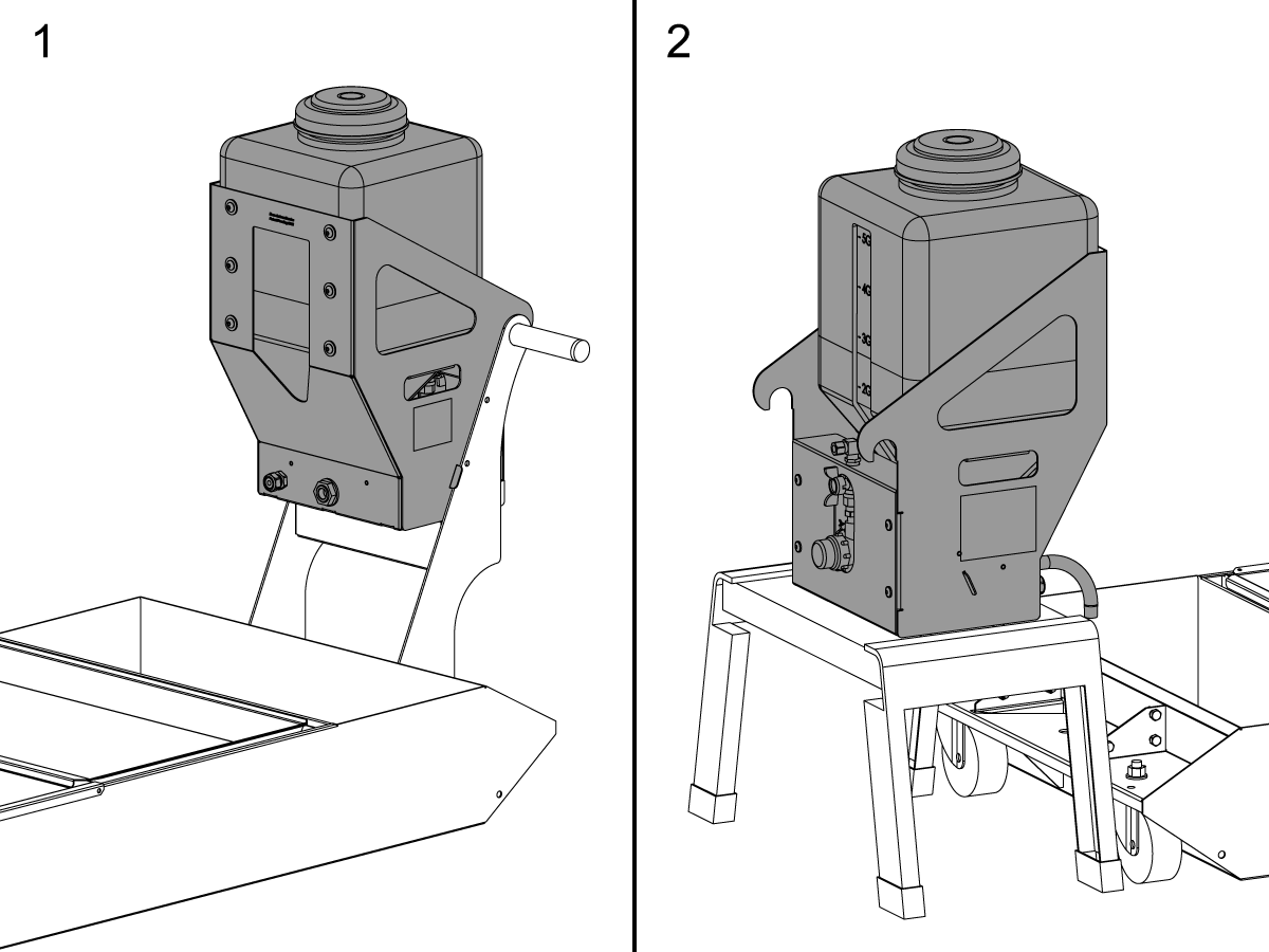
  1. Coolant Tank Mount
  2. Stand Alone Mount

The Coolant Refill option features include:

  • Automatically monitors the machine coolant level.
  • Mixes shop water supply with coolant concentrate at user controlled ratios.
  • Adds correctly mixed coolant at a specified concentration as necessary.
  • Saves time by keeping the machine operator in front of the machine producing parts and not behind the machine mixing coolant.

 WARNING: DO NOT ADD POWDERED/LIQUID COOLANT ADDITIVES TO THE COOLANT REFILL TANK.  THIS WILL DAMAGE THE SOLENOIDS AND VOID YOUR WARRANTY. ALL ADDITIVES MUST BE ADDED AND MIXED IN THE COOLANT TANK.

This Document Applies to these kits:

  • KIT PN 93-1000287: COOLANT REFILL SYSTEM
  • KIT PN 93-1000572: STAND ALONE MOUNT KIT

Note: Machines that require the stand alone mount must order both service kits.

Updated

Machines that require the Stand Alone Mount Kit are listed below:

  • All UMC-500/SS
  • UMC-750/SS with 120 Pocket SMTC
  • UMC-1000/SS with 120 Pocket SMTC
  • DC-1
  • DC-1/40
  • DC-2
  • DC-2/40
  • DC-4/40
  • Minimill
  • Super Minimill
  • ST-10/Y
  • ST-15/Y
  • PMC-500SS
  • EC-1600/ZT/ZT-5AX

Machine Compatibility

  • Mill software 18.22A or higher.
  • Lathe software 11.18A or higher.
  • Next Generation Control software 100.16.000.1010 or higher.

Tools Required

  • Refractometer
  • Bucket - 2 Gallon
  • Clamp Pliers 

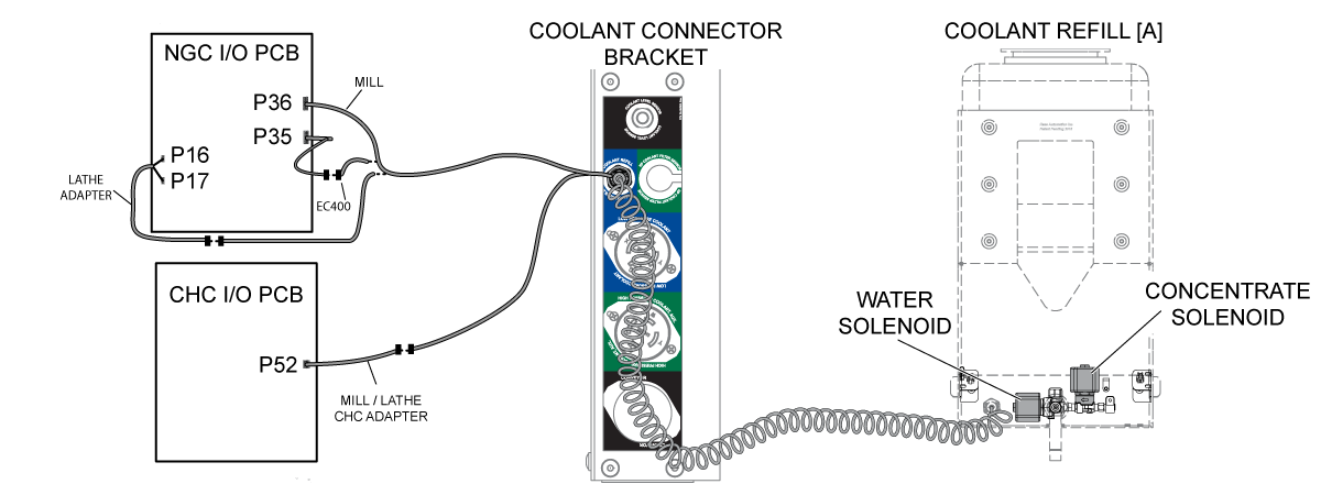
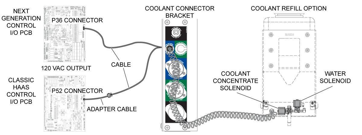
Electrical Diagram

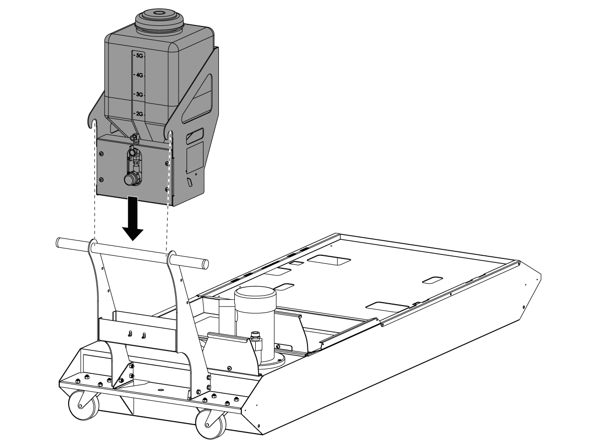
Tank Handle - Installation

1

Install the COOLANT REFILL onto the handle of the coolant tank as shown.

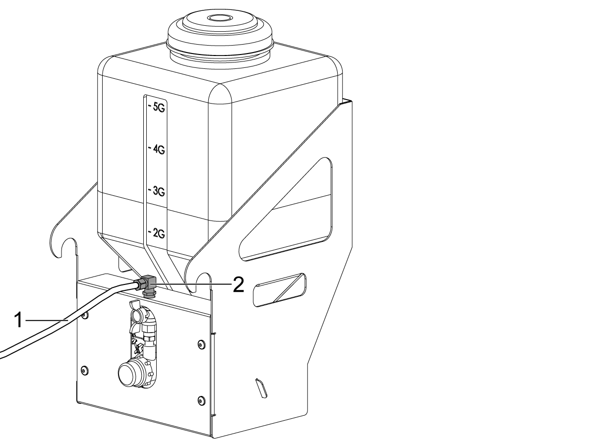
2

Install the water hose [1] into the elbow fitting [2].

3

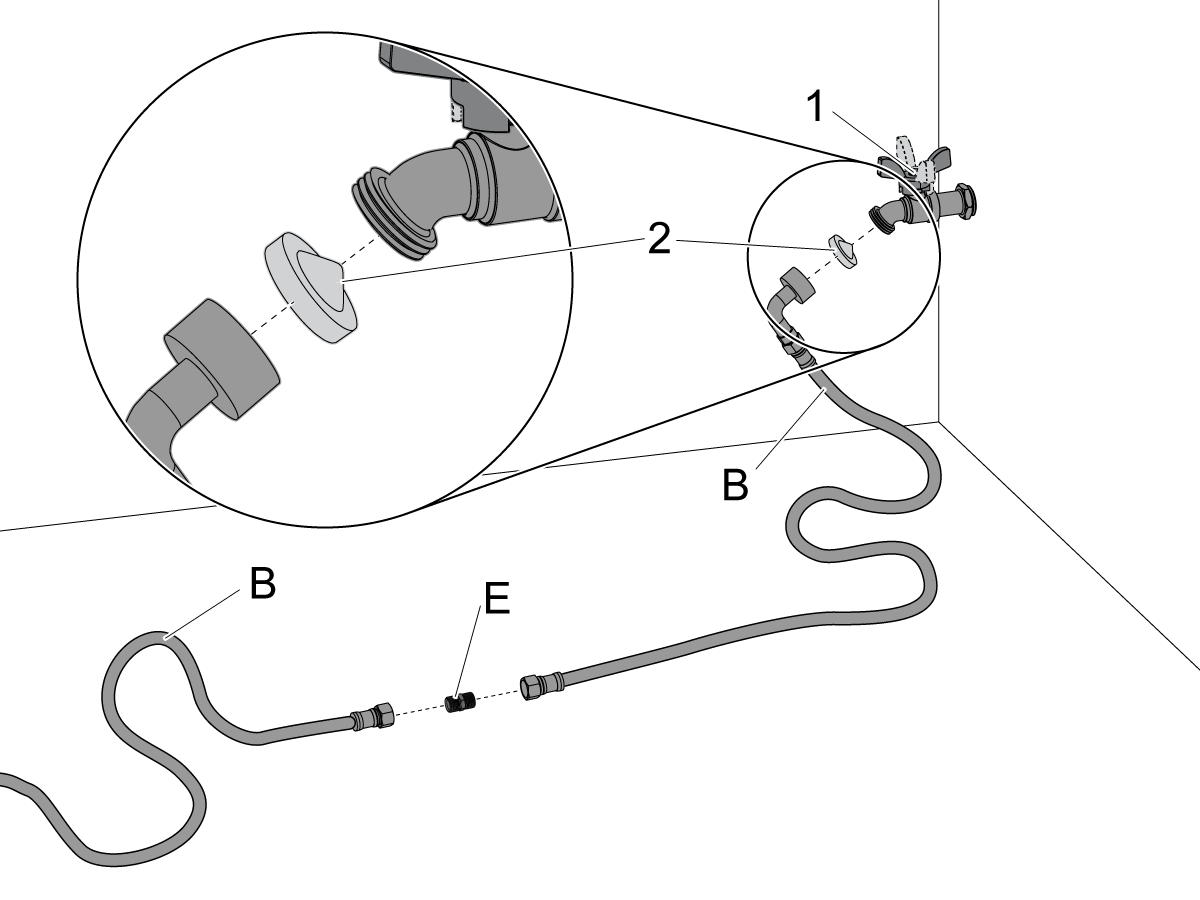
Connect the HOSE [B] to the water supply [1].

Make sure the screen filter [2] is installed in the hose fitting for the water supply.

 Note: The Cone Side Of The Screen Filter [2] Must Point Toward The Water Supply.

Order additional supply HOSES [B] (comes with fitting [E]) from www.HaasParts.com or from any hardware store - 3/8" appliance supply line.

Start the water supply. Check for leaks.

 Note: The water supply must have a pressure of 40-100 psi (2.8-6.9 bar) to correctly produce the desired coolant concentration.

4

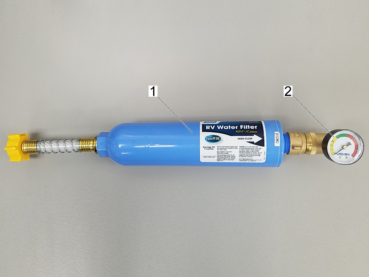
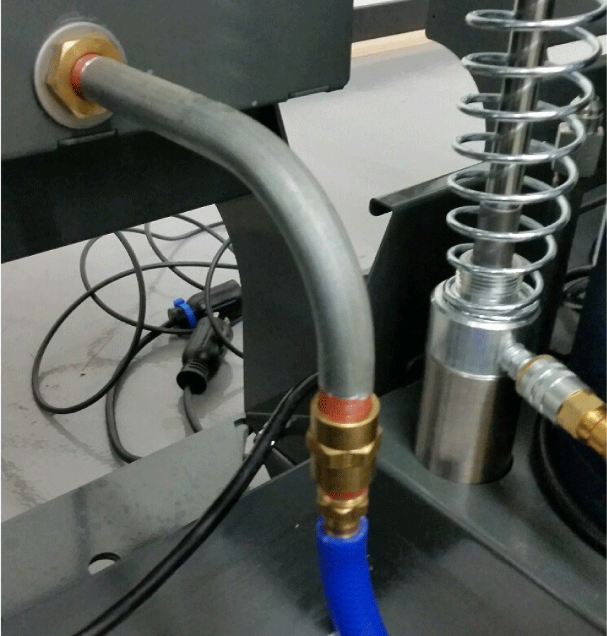
Important: To prevent damage to the solenoid valve, make sure the screen filter is installed to clean the incoming water. Debris in the solenoid valve causes it to stay open. This causes inconsistent coolant mixing, and it could also overfill the coolant tank. Your water supply may require additional filtration. Add an aftermarket water filter [1] with a pressure regulator [2] if your water supply has high mineral content or other debris. The water filter and pressure regulator in the picture are not included.

5

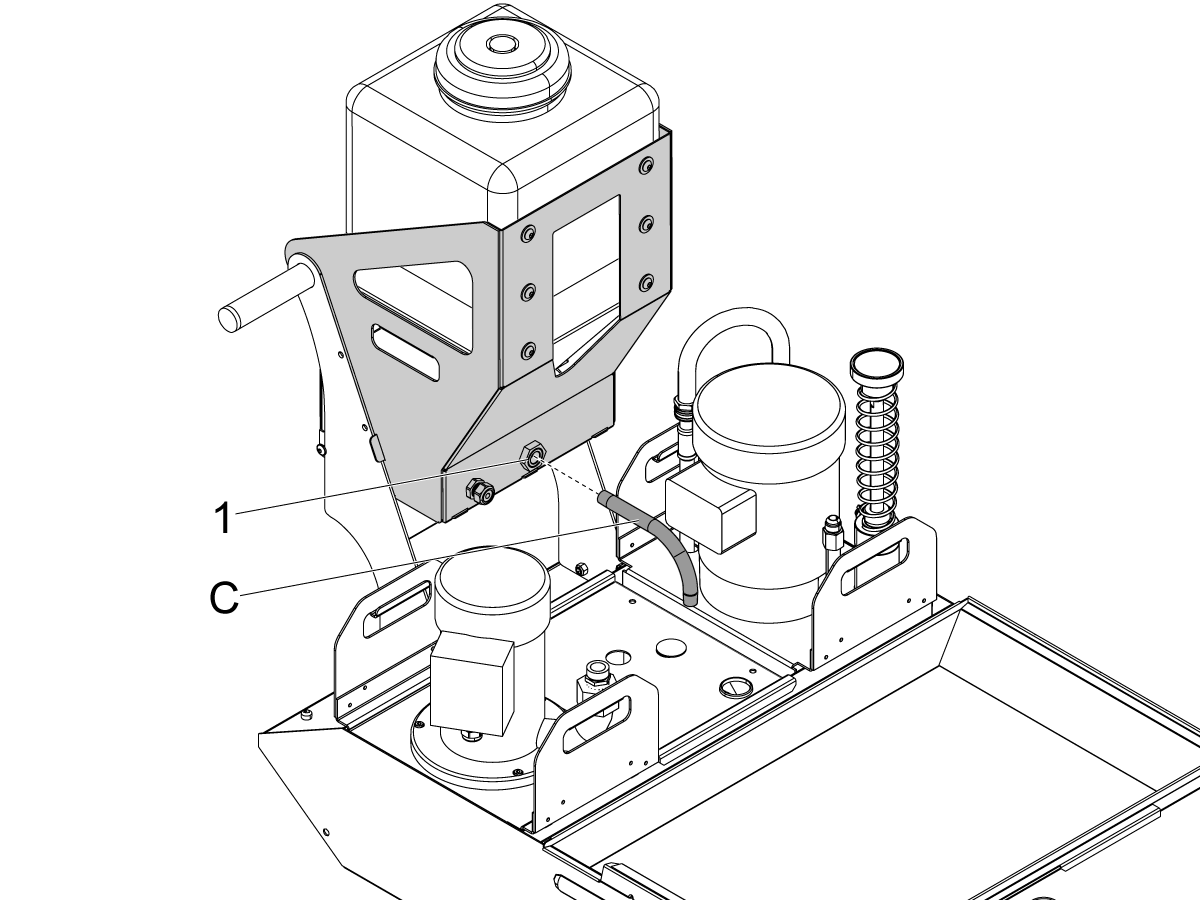
Install the NIPPLE [C] into the outlet port [1] as shown.

 Note: Move the coolant pumps so that the hole on the tank cover is under the NIPPLE [C].

6

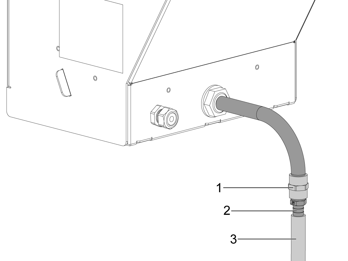
Install the Fittings: Install a 1/2" nozzle to create backpressure in the system. This is needed for thick concentrate coolants.

  • 58-1122 FITG NPT3/8F NPT3/8F STR BRASS [1]
  • 58-3048 FITG HOSE BARB1/2 NPT3/8M STR BRASS [2]
  • 58-1842 HOSE 1/2 ID PU NYLON BRAIDED [3]

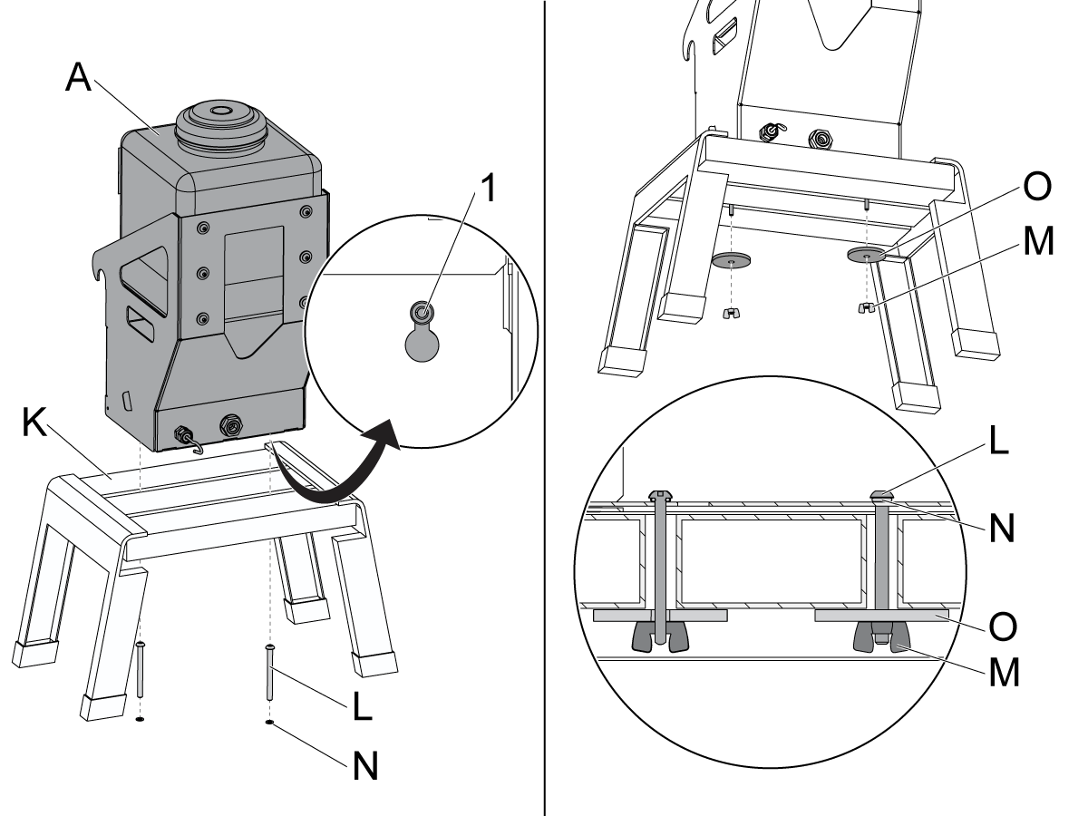
Stand Alone Mount - Installation

This section will show you how to install P/N 93-1000572, Stand Alone Mount Kit.

1

Put the ORINGS [N] over the SCREWS [L] as shown.

Put the COOLANT REFILL [A] onto the STAND [K] so the SCREWS [L] pass through the slots [1] as shown.

Install the WASHERS [O] and WING NUTS [M] to secure the COOLANT REFILL [A].

2

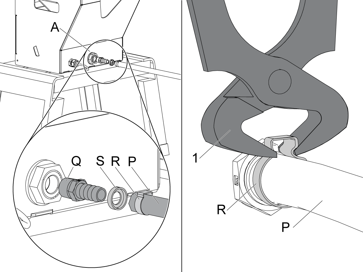
Connect the HOSE [P].

Install the parts listed as shown onto the COOLANT REFILL [A].

  • HOSE BARB [Q] 1X
  • HOSE [P] 1X
  • CAP [S] 1X
  • CLAMP [R] 1X

3

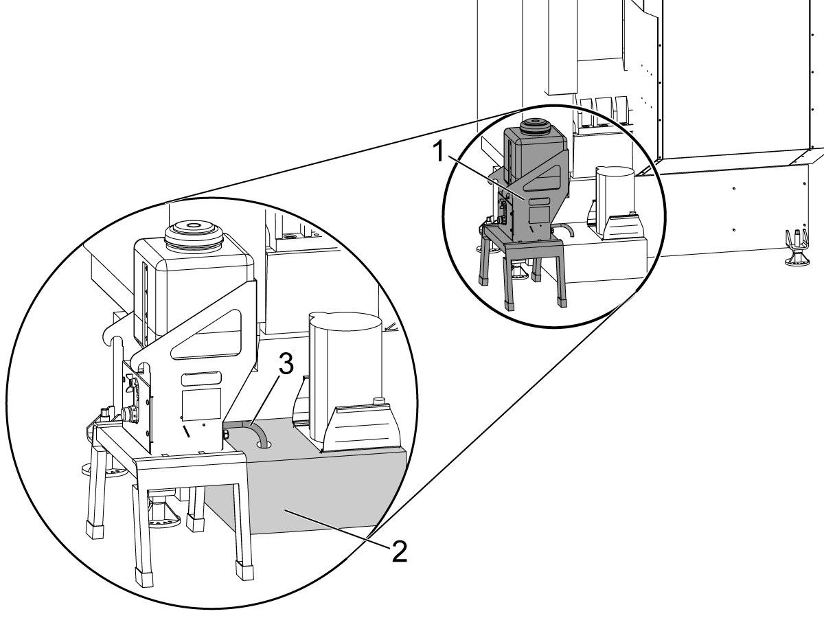
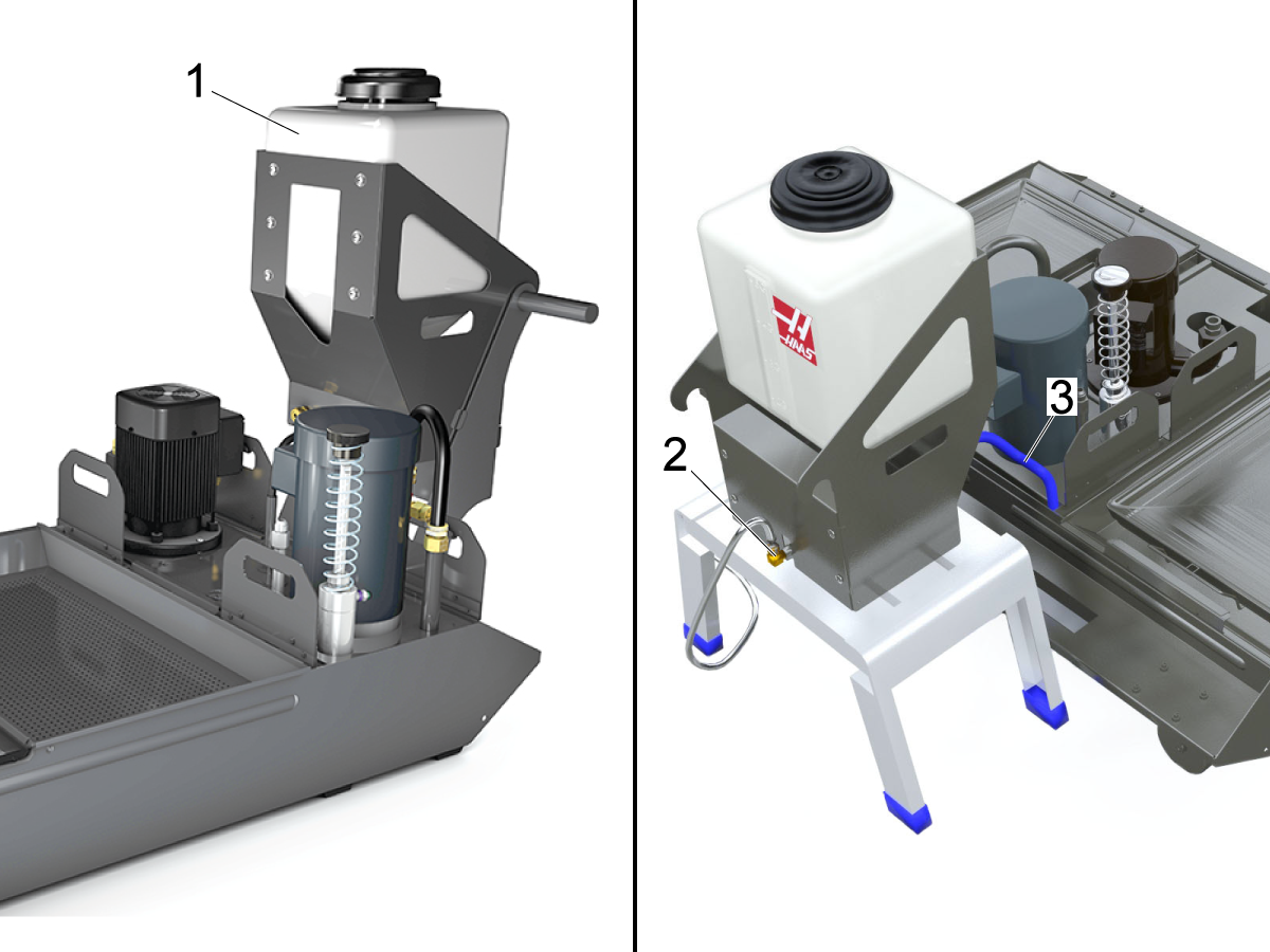
Install the COOLANT REFILL [1] near the coolant tank and coolant connector bracket.

Put the HOSE [3] in the coolant tank [2].

 Caution: The HOSE [3] must be above the tank coolant mixture.

Cut the HOSE [3] as necessary. Secure the hose.

Electrical - Installation

1

Classic Haas Control:

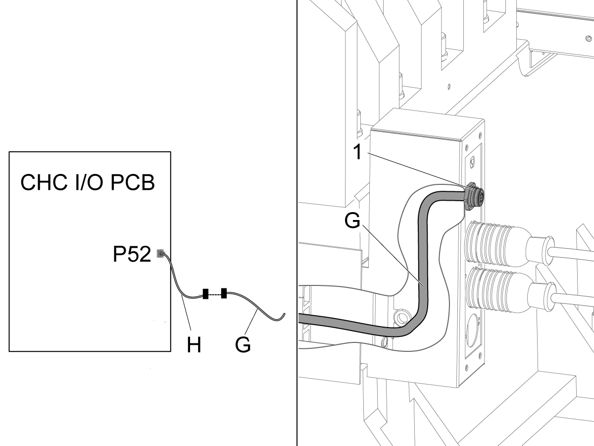
Connect the ADAPTER CABLE [H] to the CABLE [G].

Connect the ADAPTER CABLE [H] to the P52 connector on the I/O PCB.

Route the cable to the coolant connector bracket.

 Note: The coolant connector bracket is always located near the coolant tank.

Find the location on the coolant connector bracket that has the label COOLANT REFILL [1]. Install the other end of the CABLE [G] at this location. 

 Note: Drill a hole on the coolant connector bracket if it does not have this location.

2

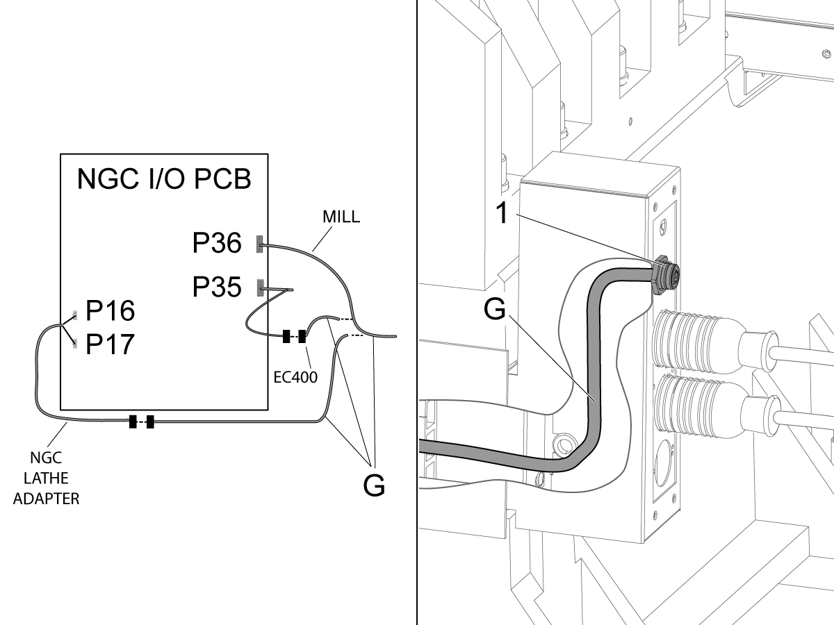
Next Generation Control:

  • Mill: Connect the CABLE [G] to the P36 connector on the I/O PCB.
  • EC-400: Connect the CABLE [G] to the P35 pigtail on the I/O PCB.
  • Lathe: Use the ADAPTER CABLE [K] on CABLE [G] and plug it into P16 and P17 on the I/O PCB.

Route the cable to the coolant connector bracket.

 Note: The coolant connector bracket is always located near the coolant tank.

Find the location on the coolant connector bracket that has the label COOLANT REFILL [1]. Install the other end of the CABLE [G] to this location.

3

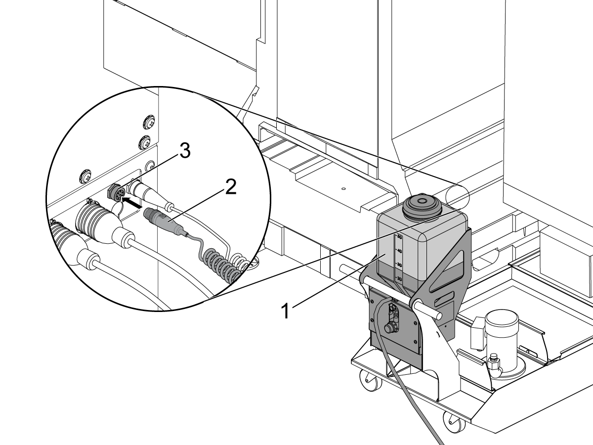
Connect the power cable [2] for the COOLANT REFILL [1] to the CABLE [3] in the coolant connector bracket..

Fill the COOLANT REFILL [1] with 5 gallons of coolant concentrate.

Push [POWER ON].

4

Classic Haas Control.

Change Setting 7 to OFF.

Push [EMERGENCY STOP].

Set Parameter 1385 to 250.

Change Setting 7 to ON.

Push [CURNT COMDS]. Push [PAGE DOWN] until the [COOLANT REFILL] display shows.

Push [F4] to set the Max gal. coolant added before repleshing concentrate.

Push [Y].

Change Setting 7 to OFF.

Push [EMERGENCY STOP].

Set Parameter 1385 to 250.

Change Setting 7 to ON.

Push [CURNT COMDS]. Push [PAGE DOWN] until the [COOLANT REFILL] display shows.

Push [F4] to set the Max gal. coolant added before repleshing concentrate.

Push [Y].

5

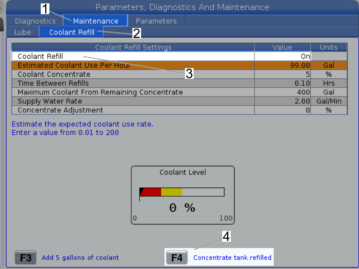
Next Generation Control:

Push [DIAGNOSTIC].

Navigate to the Maintenance tab [1].

Navigate to the Coolant Refill tab [2].

Select Coolant Refill [3].

Select ON.

Push [ENTER].

Push [F4] [4] to set the Maximum Coolant From Remaining Concentrate.

Push [Y].

6

Calibrate the Coolant Refill.

12.2 Coolant Refill - Calibration

Next Generation Control - Coolant Refill - Calibration

Push [DIAGNOSTIC].

Push the [RIGHT] cursor arrows to select the Maintenance tab.

Push the [DOWN] and [RIGHT] cursor arrows to select the Coolant Refill tab.

Fill the Coolant Refill container with 5 gallons of coolant concentrate.

Push [F4] to set the Maximum Coolant From Remaining Concentrate.

Push [Y].

Remove the filler hose from the filler pipe.

Put a bucket under the filler pipe.

Push [F3] to fill the bucket.

Push [F3] again to stop when the coolant mixture fills the bucket.

Measure the concentration of the coolant. Refer to the Maintaining Your Coolant Mixture video.

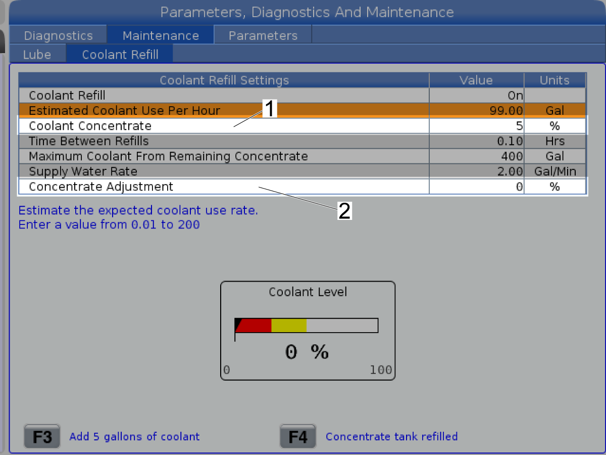
If the measured concentration is lower than the value for the Coolant Concentrate [1], increase the value for the Concentrate Adjustment [2].

If the concentration is higher than the value for the Coolant Concentrate [1], decrease the value for the Concentrate Adjustment [2].

Repeat the measurements until the concentration matches the value for Coolant Concentrate[1].

 WARNING: DO NOT ADD POWDERED/LIQUID COOLANT ADDITIVES TO THE COOLANT REFILL TANK.  THIS WILL DAMAGE THE SOLENOIDS AND VOID YOUR WARRANTY. ALL ADDITIVES MUST BE ADDED AND MIXED IN THE COOLANT TANK.

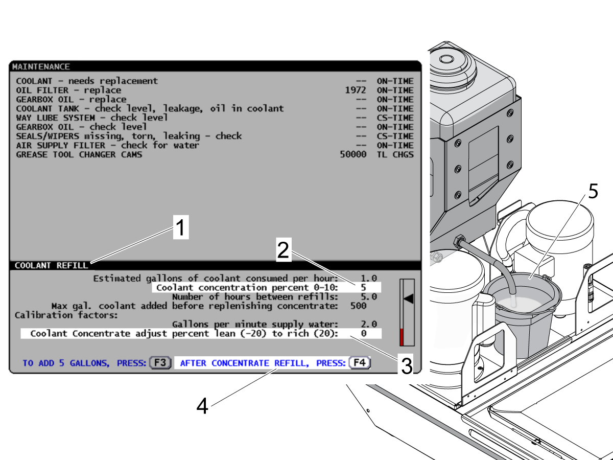
Classic Haas Control - Coolant Refill - Calibration

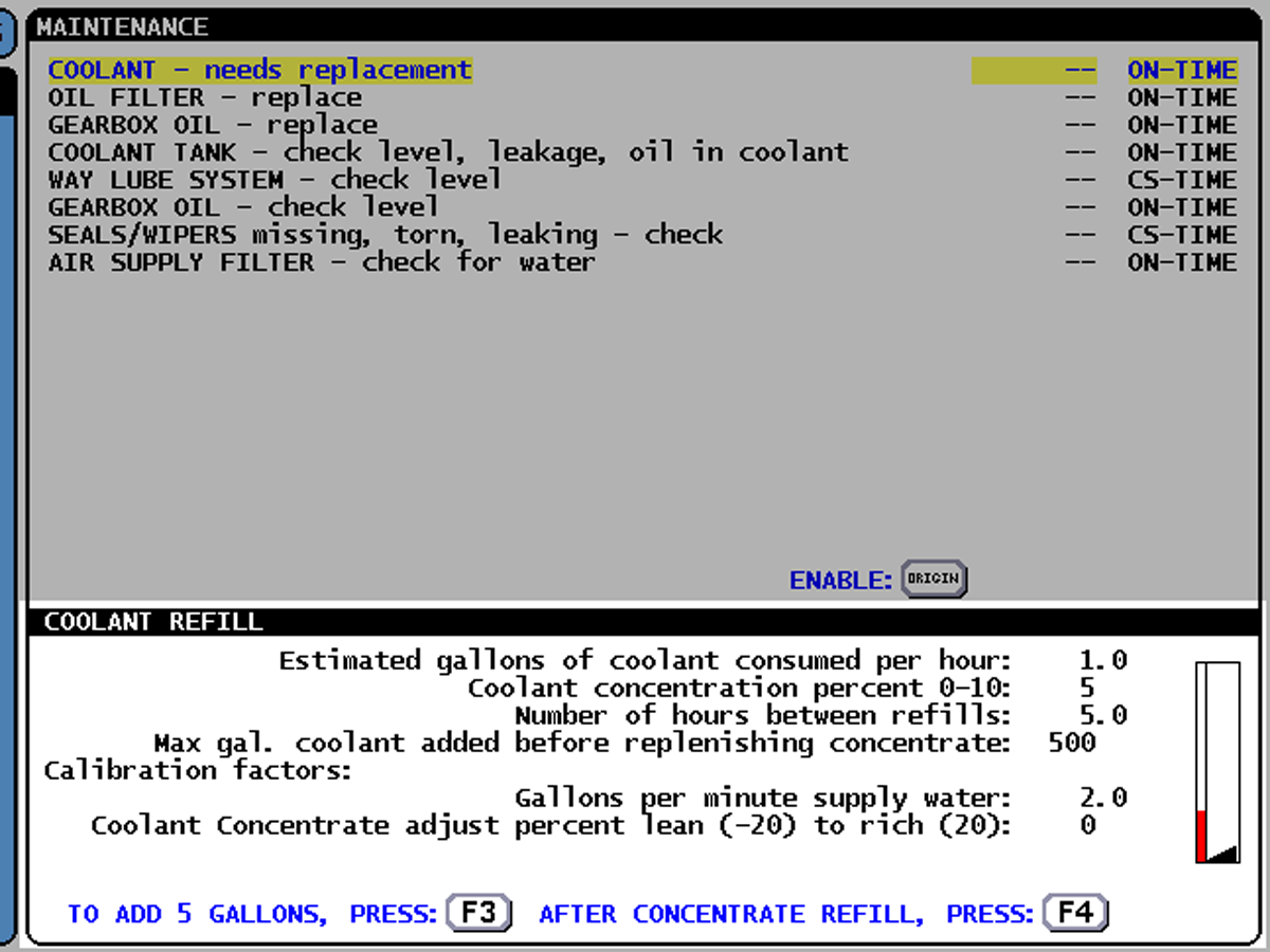
Push [CURNT COMDS]. Push [PAGE DOWN] until the Coolant Refill screen shows [1].

Fill the Coolant Refill container with 5 gallons of coolant concentrate.

Push [F4] [4] to set the Max gallons of coolant added before replenishing concentrate. Push [Y].

Remove the filler hose from the filler pipe.

Put a bucket [5] under the filler pipe.

Push [F3] to fill the bucket. Push [F3] again to stop when the coolant mixture fills the bucket.

Measure the concentration of the coolant. Refer to the Maintaining Your Coolant Mixture video.

If the measured concentration is lower than the value for the Coolant Concentration Percent[2], increase the value for the Coolant Concentration Adjust [3].

If the concentration is higher than the value for the Coolant Concentration Percent [2], decrease the value for the Coolant Concentration Adjust [3].

Repeat the measurements until the concentration matches the value for Coolant Concentration Percent [2].

Coolant Refill - Filler Hose - Installation

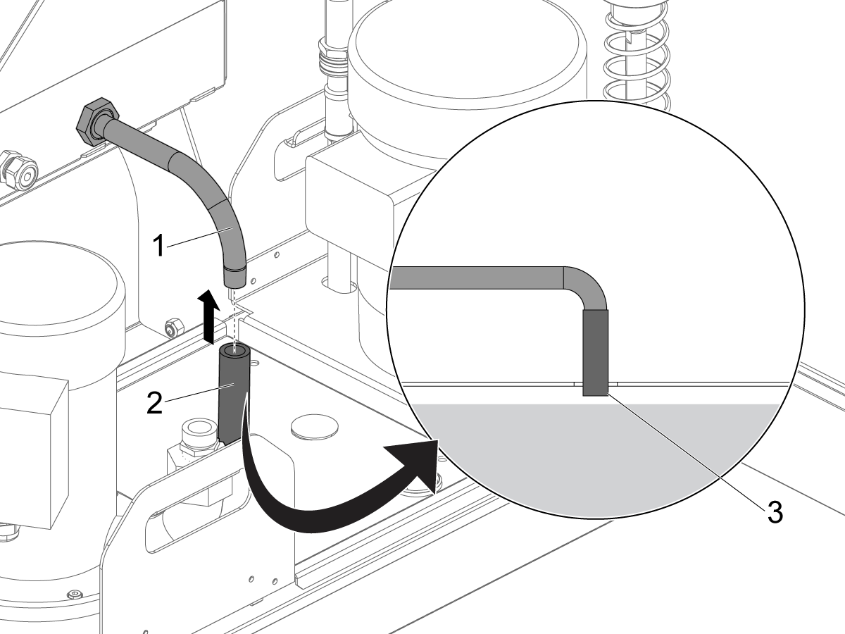
The filler hose [2] installs into the filler pipe [1].

 Caution: Make sure the filler hose does not touch the coolant [3].

12.3 Coolant Refill - Operation

Introduction

The Coolant Refill assembly does these tasks automatically:

  1. Mixes water with coolant concentrate.
  2. Adds coolant to the coolant tank.

You can set values that control how the Coolant Refill operates. This decreases the work necessary to keep the correct level and concentration of coolant in your tank.

Components

  1. Coolant concentrate container
  2. Water supply hose
  3. Coolant Filler pipe/hose

Use these types of coolant concentrate for the Coolant Refill:

  • Soluble oil
  • Synthetic
  • Semi Synthetic

Requirements

  1. Classic Haas Control: Mill software 18.22A or higher and lathe software 11.18A or higher.
  2. Next Generation Control: Software 100.16.000.1010 or higher.

 WARNING: DO NOT ADD POWDERED/LIQUID COOLANT ADDITIVES TO THE COOLANT REFILL TANK.  THIS WILL DAMAGE THE SOLENOIDS AND VOID YOUR WARRANTY. ALL ADDITIVES MUST BE ADDED AND MIXED IN THE COOLANT TANK.

Installation

Refer to the Coolant Refill installation procedure.

Next Generation Control Operation

To view the Coolant Refill page:

Push [DIAGNOSTIC].

Select the Maintenance tab.

Select the Coolant Refill tab.

To set a value:

Highlight a setting. Enter the value. Push [ENTER].

Settings for the Coolant Refill:

Setting Description Default Value Range
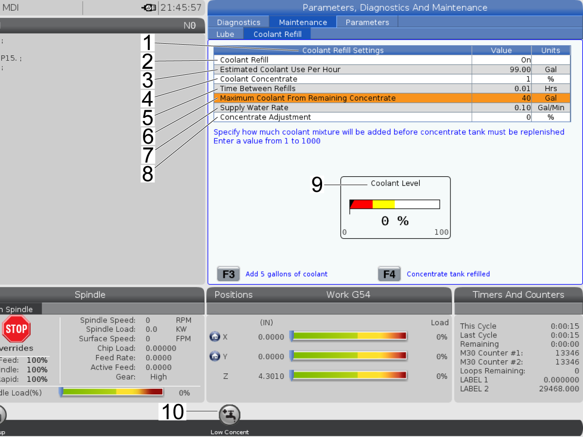
Coolant Refill [2] This setting activates or deactivates the Coolant Refill option. Off On or Off
Estimated Coolant Use Per Hour [3] This is the quantity of coolant lost to the environment in an hour of detected coolant use.* 1.0 .01 - 99 gallons/hour
Coolant Concentrate[4] This is the correct coolant concentration necessary for the application. 5 0 - 10 %
Time Between Refills[5] This is the quantity of time between automatic coolant refills. 5.0 0.1 - 999.8 hours
Maximum Coolant From Remaining Concentrate[6] This is the quantity of coolant mixture that flows into the coolant tank before the coolant concentrate container is empty. 500 20 - 1000 gallons
Supply Water Rate [7] This is the quantity of water flow from the water supply. Measure the water flow from the water supply and enter that value here. 2.0 0.1 - 99.9 gallons/minute
Concentrate Adjustment [8]

This is the accurate adjustment of the measured coolant concentration. Increase or decrease this value to make the measured coolant concentration the same as the value in Coolant concentration percent [3].**

0 (-20) - 20
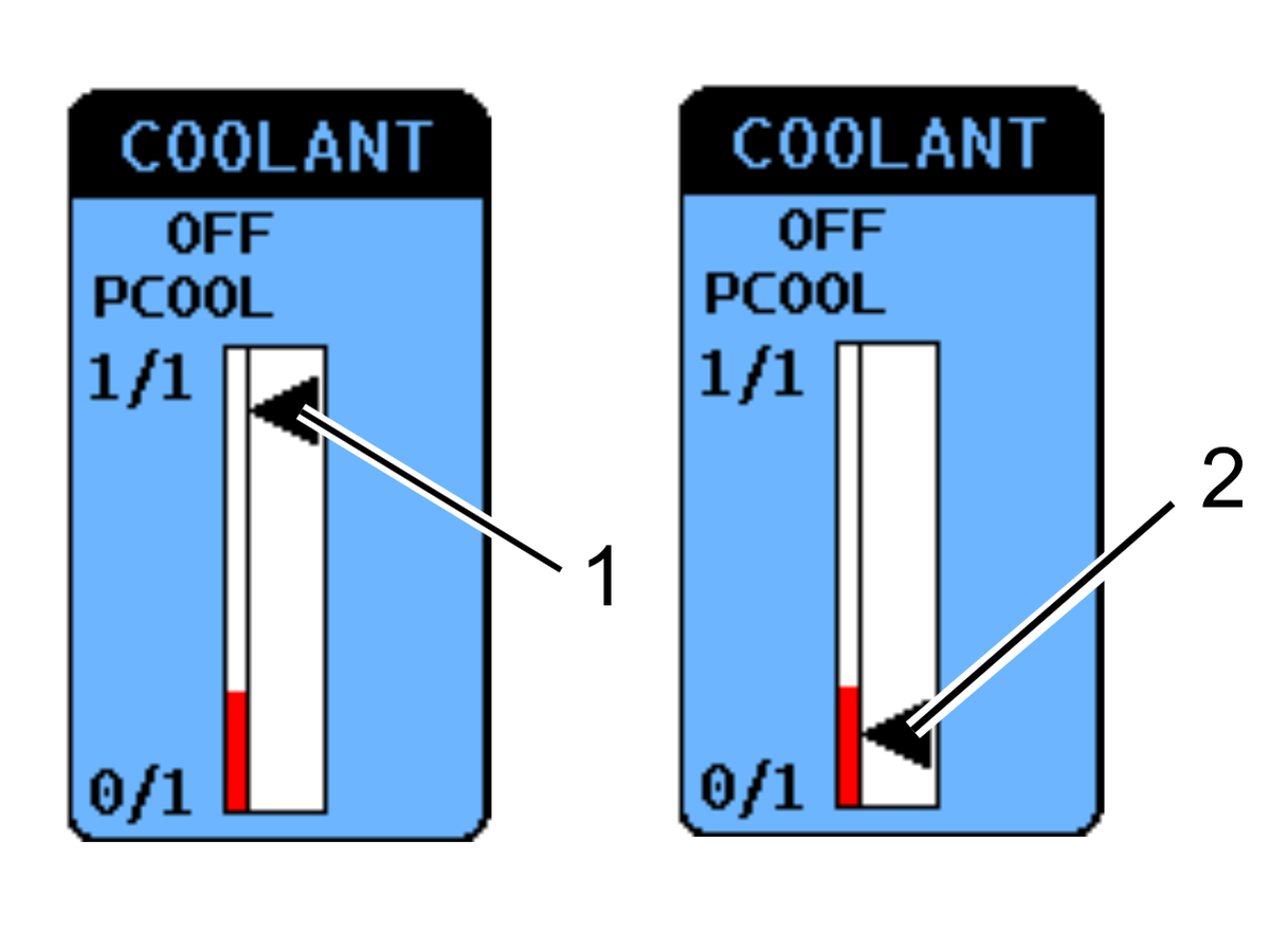
Coolant Level [9] This gauge shows the level of coolant mixture in the coolant tank. N/A N/A
Low Coolant Concentrate Warning[10]

This Low Concentrate icon shows when the value in Maximum Coolant From Remaining Concentrate [6] becomes 40. This lets you fill the coolant concentrate container before it becomes empty.

When the value becomes 0, the Coolant Refill system operation stops. This lets you fill the coolant concentrate container.

To keep the system in operation, fill the coolant concentrate container before it becomes empty.

N/A N/A

*The control monitors coolant use as the quantity of time the pumps are on.

**Refer to the Coolant Refill - Calibration procedure.

Operation - Classic Haas Control

To view the COOLANT REFILL page:

Push [CURNT COMNDS]. Push [PAGE DOWN] until the COOLANT REFILL page shows.

To set a value:

Highlight a setting. Enter the value. Push [WRITE/ENTER].

Settings for the Coolant Refill:

Setting Description Default Value Range
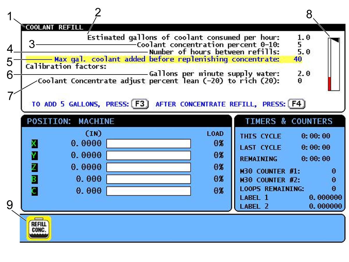
Estimated gallons of coolant consumed per hour [2] This is the quantity of coolant lost to the environment in an hour of detected coolant use.* 1.0 .01 - 99 gallons/hour
Coolant concentration percent [3] This is the correct coolant concentration necessary for the application. 5 0 - 10 %
Number of hours between refills [4] This is the quantity of time between automatic coolant refills. 5.0 0.1 - 999.8 hours
Max gal. coolant added before replenishing concentrate [5] This is the quantity of coolant mixture that flows into the coolant tank before the coolant concentrate container is empty. 500 20 - 1000 gallons
Gallons per minute supply water [6] This is the quantity of water flow from the water supply. Measure the water flow from the water supply and enter that value here. 2.0 0.1 - 99.9 gallons/minute
Coolant Concentrate adjust percent lean [7]

This is the accurate adjustment of the measured coolant concentration. Increase or decrease this value to make the measured coolant concentration the same as the value in Coolant concentration percent [3].**

0 (-20) - 20
Coolant level sensor gauge [8] This gauge shows the level of coolant mixture in the coolant tank. N/A N/A
Low coolant concentrate warning [9]

This REFILL CONC. icon shows when the value in Maximum gallons coolant added before replenishing concentrate [5] becomes 40. This lets you fill the coolant concentrate container before it becomes empty.

When the value becomes 0, the Coolant Refill system operation stops. This lets you fill the coolant concentrate container.

To keep the system in operation, fill the coolant concentrate container before it becomes empty.

N/A N/A

*The control monitors coolant use as the quantity of time the pumps are on.

**Refer to the Coolant Refill - Calibration procedure.

12.4 Coolant Refill - Maintenance

Maintenance

 WARNING: DO NOT ADD POWDERED/LIQUID COOLANT ADDITIVES TO THE COOLANT REFILL TANK.  THIS WILL DAMAGE THE SOLENOIDS AND VOID YOUR WARRANTY. ALL ADDITIVES MUST BE ADDED AND MIXED IN THE COOLANT TANK.

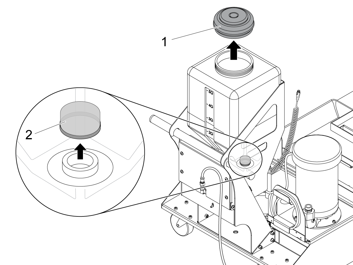
Coolant-Concentrate Filter Cleaning

  1. Remove the cap [1] from the container.
  2. Find the filter screen [2] inside at the bottom of the container. Remove the filter screen.
  3. Clean the filter screen with water.
  4. Install the filter screen and cap onto the container.

ASCO Brand Purge Solenoid

Push [POWER OFF]. 

Close off the water supply valve to the refill unit.

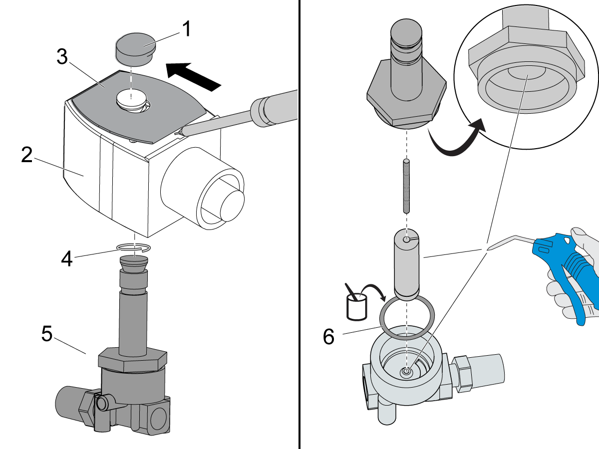
ASCO air purge solenoid:

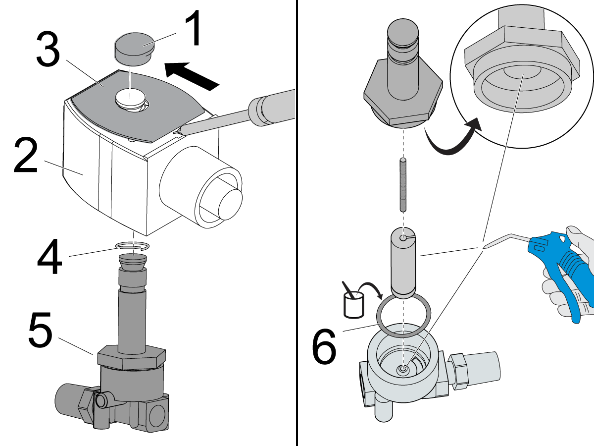
  • Remove the red cap [1].
  • Push the solenoid coil assembly [2] down to compress the spring inside.
  • Remove the specification plate [3] by sliding off.
  • Remove the split spring [4] and valve subassembly [5] from the coil assembly [2].
  • Disassemble the valve subassembly [5].
  • Clean the parts with compressed air. Be sure to remove all debris from inside the valve.
  • Apply a thin coat of silicone grease to the body gasket [6].
  • Assemble the components in the opposite order they were removed.
  • Open the primary air valve. Make sure there are no leaks.

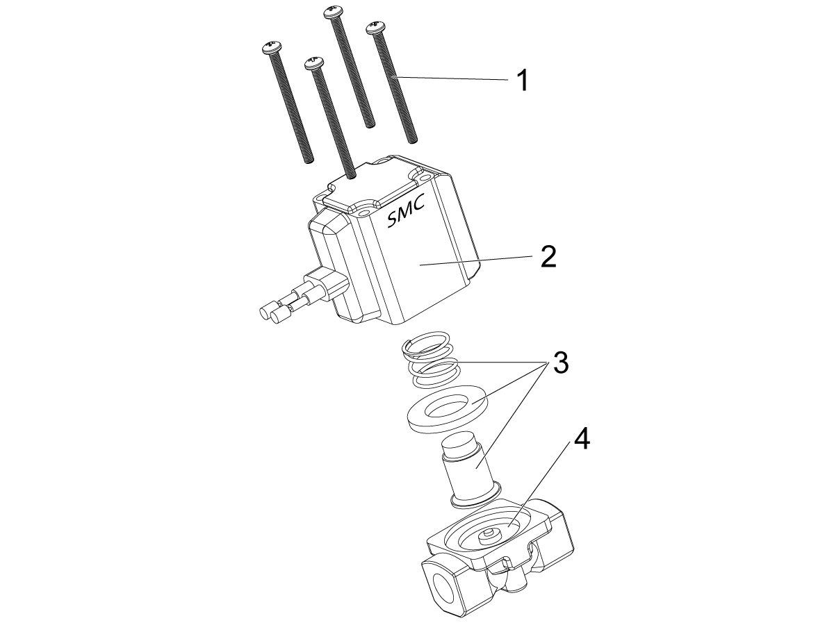
SMC Brand Purge Solenoids

Push [POWER OFF]. 

Close off the water supply valve to the refill unit.

SMC air purge solenoid:

  • Remove the four screws [1].
  • Remove the solenoid coil assembly [2].
  • Clean the internal solenoid parts [3] with compressed air. Be sure to remove all debris from inside the valve [4].
  • Apply a thin coat of silicone grease to the rubber seals.
  • Assemble the components in the opposite order they were removed.

FESTO Brand Purge Solenoids

Push [POWER OFF]. 

Close off the water supply valve to the refill unit.

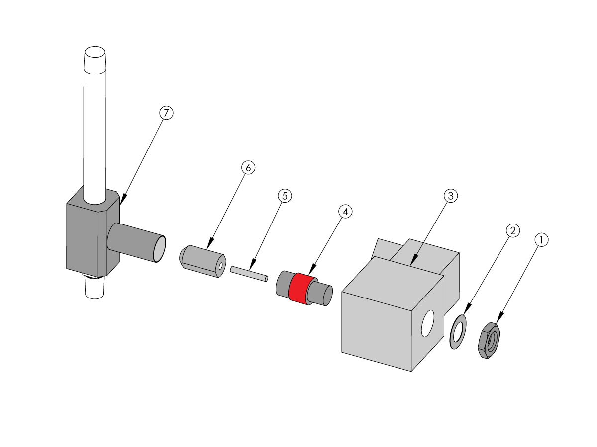
FESTO air purge solenoid: 

  • Remove the nut [1].
  • Remove the washer [2].
  • Remove the solenoid coil [3]. Note the orientation of the coil.
  • Remove the plug nut [4]. 

 NOTE: Hold the outside diameter (pictured RED) of the plug nut in the vice with the aluminum jaws to prevent the damage.

  • Remove the spring [5].
  • Remove the valve poppet [6].
  • Use the compressed air to clean the valve body [7] valve poppet and the spring.
  • Clean the old thread sealant off the plug nut threads and apply fresh sealant.
  • Assemble the solenoid in the reverse order.

12.5 Coolant Refill - Troubleshooting

Recently Updated

Coolant Refill Option - Troubleshooting Guide


TG0055

Revision A - 02/2026

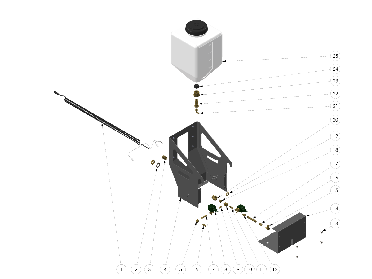
Exploded View

 WARNING: DO NOT ADD POWDERED/LIQUID COOLANT ADDITIVES TO THE COOLANT REFILL TANK.  THIS WILL DAMAGE THE SOLENOIDS AND VOID YOUR WARRANTY. ALL ADDITIVES MUST BE ADDED AND MIXED IN THE COOLANT TANK.

  1. COOLANT REFILL SOLENOID COIL CABLE
  2. WASHER 1 STEEL .120THK X1.562O
  3. STRN RLF PG13.5 .12"-.27" CD13BR-BK-N
  4. COOLANT REFILL OPTION CHASSIS
  5. FITG NPT1/8F NPT1/8F 90 BRASS
  6. NIPPLE HEX 1/8 NPTM X 3/8 SMOOTH
  7. NIPPLE 1/8 NPT X 2 BRASS
  8. SOLENOID AIR 2 P0RT 2 POS 1 COIL 1/8NPT
  9. NIPPLE 1/8 NPT X 1 HEX BRASS
  10. FITG NPT1/8M NPT1/8F NPT1/8F TEE BRASS
  11. VENTURI NOZZLE
  12. FITG REDUCER NPT1/4F NPT1/8M STR BRASS
  13. FBHCS 1/4-20 X 1/2 LOCTITE
  14. COOLANT REFILL OPTION COVER
  15. FITG COMP 3/8 X 1/4 MNPT 90 BR
  16. FITG NPT1/4F NPT1/4F STR BRASS
  17. NIPPLE 1/4 NPT X 3 1/2 BRASS
  18. FITG REDUCER NPT3/8M NPT1/8F BRASS
  19. STRN RLF PG13.5 .12"-.27" CD13BR-BK-N
  20. FITG NPT3/8 X DIA 1.000 BKHD BRASS
  21. FITG HOSE BARB-3/8 X NPT-3/8-M 90
  22. FITG BLKHD NPT3/8M/F X NPT3/4M X 2-1/2L
  23. FITG REDUCER NPT1-1/4M NPT3/4F NYLON
  24. GREASE STRAINER
  25. 5G TANK

Introduction

The image show the following components of the coolant refill system.

  1. Coolant concentrate tank
  2. Strainer
  3. Solenoid cable
  4. Filler hose
  5. Water solenoid cable
  6. Coolant concentrate solenoid cable

Symptom Table

Symptom Possible Cause Corrective Action
The coolant concentration in the coolant tank is incorrect. There is insufficient water pressure. Check the incoming water pressure.
The CRO is not calibrated. Calibrate the CRO.
The water supply or coolant concentrate solenoid does not receive voltage. Measure the voltage to the solenoids.
The water supply or coolant concentrate solenoid is contaminated and stays on. Clean the solenoids.
Thick concentrate, high viscosity. Install 1/2" nozzle on fill tube.
The CRO does not power on. The water supply or coolant concentrate solenoid does not receive voltage. Measure the voltage to the solenoids.
The coolant level sensor does not operate correctly. Troubleshoot the coolant level sensor.
The coolant tank overfills. The water supply or coolant concentrate solenoid is contaminated and stays on. Clean the solenoids.
The coolant level sensor does not operate correctly. Troubleshoot the coolant level sensor.
Weak output flow to coolant refill  Orifice is too small in venturi valve causing weak flow.  Order new venturi valve 20-6616 with a larger orifice.

Coolant Concentration and Ratios

Make sure that the water supply has the correct pressure. The water supply must have a pressure of 40-100 psi (2.8-6.9 bar) to produce the desired coolant concentration.

Make sure the water supply screen [1] is not clogged. Clean the screen [1] if it is clogged. Make sure the cone side of the screen points toward the water supply. Make sure that the hose [2] is straight and does not have kinks.

If an aftermarket water filter is installed, make sure it is not clogged.

To correct the batch of coolant that is in the coolant tank, refer to the video Machine Tool Coolant - Top Up High Concentration - Video

The system may need to be calibrated to produce the correct coolant concentration. For calibration instructions, refer to Coolant Refill - Calibration.

Electrical Fault

Disconnect the cable from the CRO unit to the coolant connector bracket on the side of the machine.

For this section, complete all voltage measurements with the CRO unit commanded ON. On the Coolant Refill display, press [F3] to Add 5 gallons of coolant. Press [F3] again when you are ready to stop the CRO.

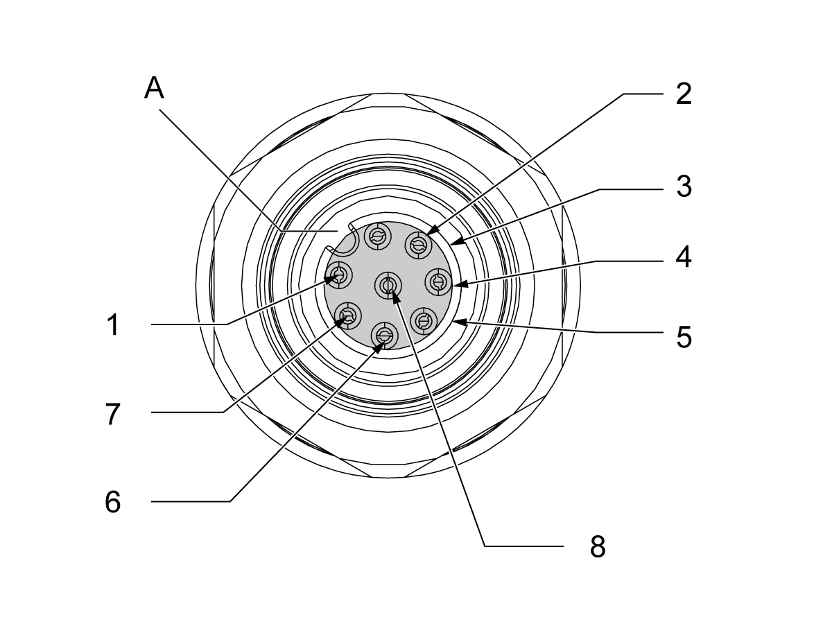
 Note: Use the notch [A] in the connector as a reference to find the correct pin.

Measure the voltage to the water supply solenoid [1]: The voltage across pins 2 and 5 of the connector on the coolant connector bracket must measure 120 VAC.

Measure the voltage to the coolant concentrate solenoid [2]: The voltage across pins 1 and 4 of the connector on the coolant connector bracket pulses on and off for 0.25 seconds each time it activates. Set your multimeter to Min/Max.

If the voltage is correct at the connector bracket:

  1. Connect the cable from the CRO to the coolant connector bracket.
  2. Shut off the water source.
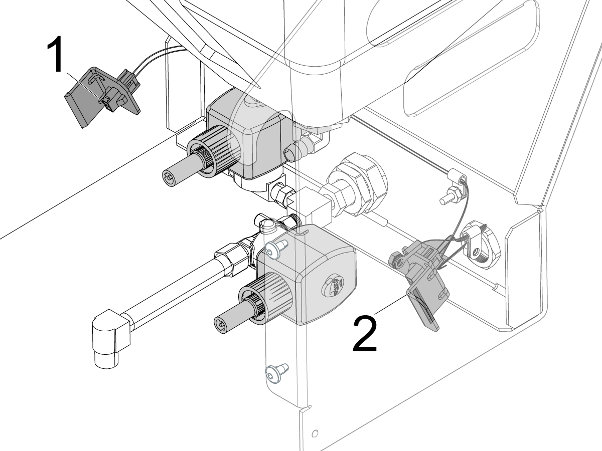
  3. Measure for the voltage at the solenoid connectors [1 and 2]. They must measure 120 VAC. If there is no voltage at the solenoids, the solenoid cable from the CRO to the coolant connector bracket is at fault.
  4. If the voltage to the solenoids is correct, clean the solenoids. Go to Section 5.

If there is no voltage at the coolant connector bracket: Go to the applicable link below to troubleshoot the I/O PCB.

  • NGC I/O PCB Troubleshooting
  • CHC I/O PCB Troubleshooting

Solenoid Malfunction

Clean the solenoid: Remove the red cap [1]. Push the solenoid coil assembly [2] down to compress the split spring [4] inside.

Remove the specification plate [3]. Remove the split spring [4] and valve subassembly [5] from the coil assembly [2].

Disassemble the valve subassembly [5]. Clean the parts with compressed air. Be sure to remove all debris from inside the valve. Apply a thin coat of high-grade silicone grease to the body gasket [6].

1/2" Nozzle on Fill Tube

Install the Fittings: Install a 1/2" nozzle to create backpressure in the system. This is needed for thick concentrate coolants.

  • 58-1122 FITG NPT3/8F NPT3/8F STR BRASS
  • 58-3048 FITG HOSE BARB1/2 NPT3/8M STR BRASS
  • 58-1842 HOSE 1/2 ID PU NYLON BRAIDED

Electrical Diagram

Recently Viewed Items

You Have No Recently Viewed Items Yet

Feedback
Haas Logo

Haas Delivered Price

This price includes shipping cost, export and import duties, insurance, and any other expenses incurred during shipping to a location in France agreed with you as a buyer. No other mandatory costs can be added to the delivery of a Haas CNC Product.

KEEP UP WITH THE LATEST HAAS TIPS AND TECHNOLOGY...

Sign up now!   

HAAS TOOLING ACCEPTS THE FOLLOWING:

  • Service & Support
  • Owners
  • Request Service
  • Operator Manuals
  • Haas Parts
  • Rotary Repair Request
  • Pre-Install Guides
  • Shopping Tools
  • Build & Price a New Haas
  • Available Inventory
  • The Haas Price List
  • CNCA Financing
  • About Haas
  • Accessibility Statement
  • DNSH Statement
  • Export Compliance
  • Careers
  • Certifications & Safety
  • Contact Us
  • History
  • Terms & Conditions
  • Haas Tooling Terms & Conditions
  • Privacy
  • Warranty
  • Haas Community
  • Haas Certification Program
  • Haas Motorsports
  • Gene Haas Foundation
  • Haas Technical Education Community
  • Events
  • Join the Conversation
  • Facebook
  • X
  • Flickr
  • YouTube
  • LinkedIn
  • Instagram
  • TikTok
© 2026 Haas Automation, Inc – CNC Machine Tools
This site is protected by reCAPTCHA and the Google Privacy Policy and Terms of Service apply.

2800 Sturgis Rd., Oxnard, CA 93030
Toll Free: (888) 817-4446 / Fax: 805-278-8554