-
machines
-
Vertical Mills
Vertical Mills
-
Multi-Axis Solutions
Multi-Axis Solutions
-
Lathes
Lathes
-
Horizontal Mills
Horizontal Mills
-
Rotaries & Indexers
Rotaries & Indexers
-
Special Series
Special Series
-
Automation Systems
Automation Systems
-
Desktop Machines
Desktop Machines
-
Shop Equipment
Shop Equipment
-
Fabrication Machines
Fabrication Machines
SHOPPING TOOLSWANT TO TALK TO SOMEONE?A Haas Factory Outlet (HFO) can answer your questions, and walk you through your best options.
CONTACT YOUR DISTRIBUTOR > -
Vertical Mills
-
Options
-
/2026-04-VOP-SquareComponent.jpg/_jcr_content/renditions/cq5dam.thumbnail.319.319.png) Value Option Packages
Value Option Packages
Value Option Packages
Value Option Packages -
 Spindles
Spindles
Spindles -
 Tool Changers
Tool Changers
Tool Changers -
 4th- | 5th-Axis
4th- | 5th-Axis
4th- | 5th-Axis -
 Turrets & Live Tooling
Turrets & Live Tooling
Turrets & Live Tooling -
 Probing
Probing
Probing -
 Chip & Coolant Management
Chip & Coolant Management
Chip & Coolant Management -
 The Haas Control
The Haas Control
The Haas Control -
 Product Options
Product Options
Product Options -
 Tooling & Fixturing
Tooling & Fixturing
Tooling & Fixturing -
 Workholding
Workholding
Workholding -
 5-Axis Solutions
5-Axis Solutions
5-Axis Solutions
SHOPPING TOOLSWANT TO TALK TO SOMEONE?A Haas Factory Outlet (HFO) can answer your questions, and walk you through your best options.
CONTACT YOUR DISTRIBUTOR > -
-
Why Haas
Discover the Haas Difference
-
Service
Welcome to Haas Service
- Videos
-
SHOPPING TOOLSWANT TO TALK TO SOMEONE?
A Haas Factory Outlet (HFO) can answer your questions, and walk you through your best options.
CONTACT YOUR DISTRIBUTOR > -
- Haas Tooling
- Haas Service Parts


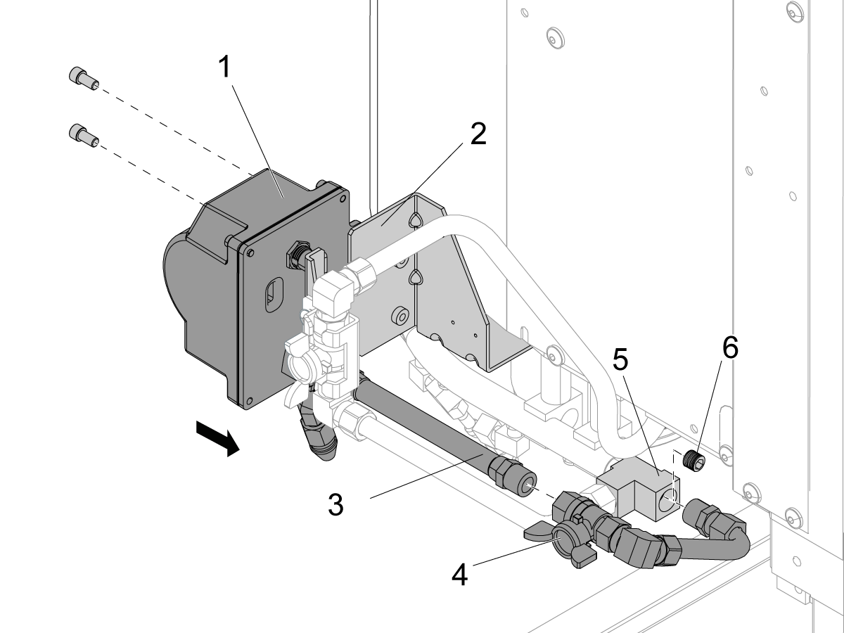
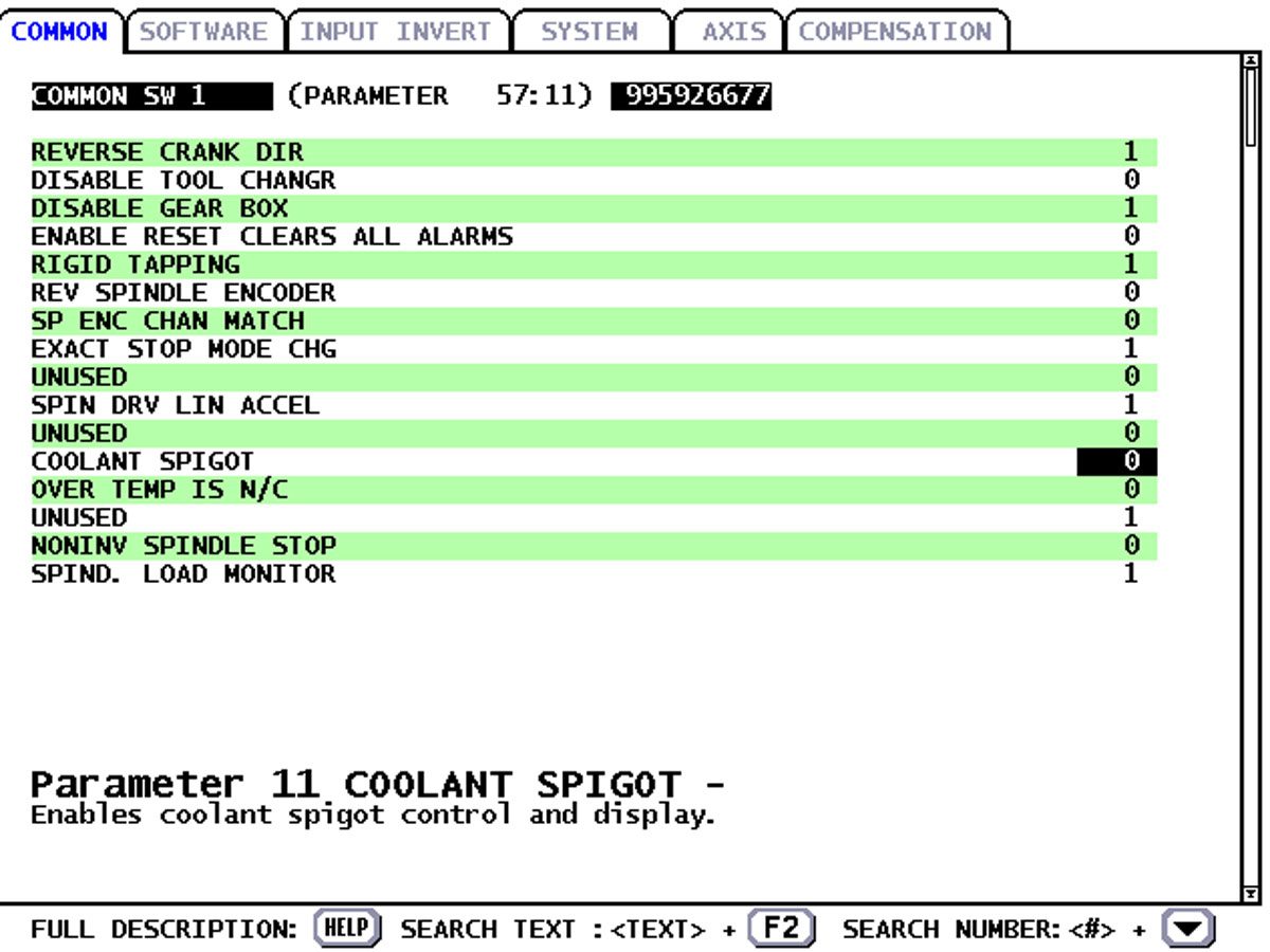
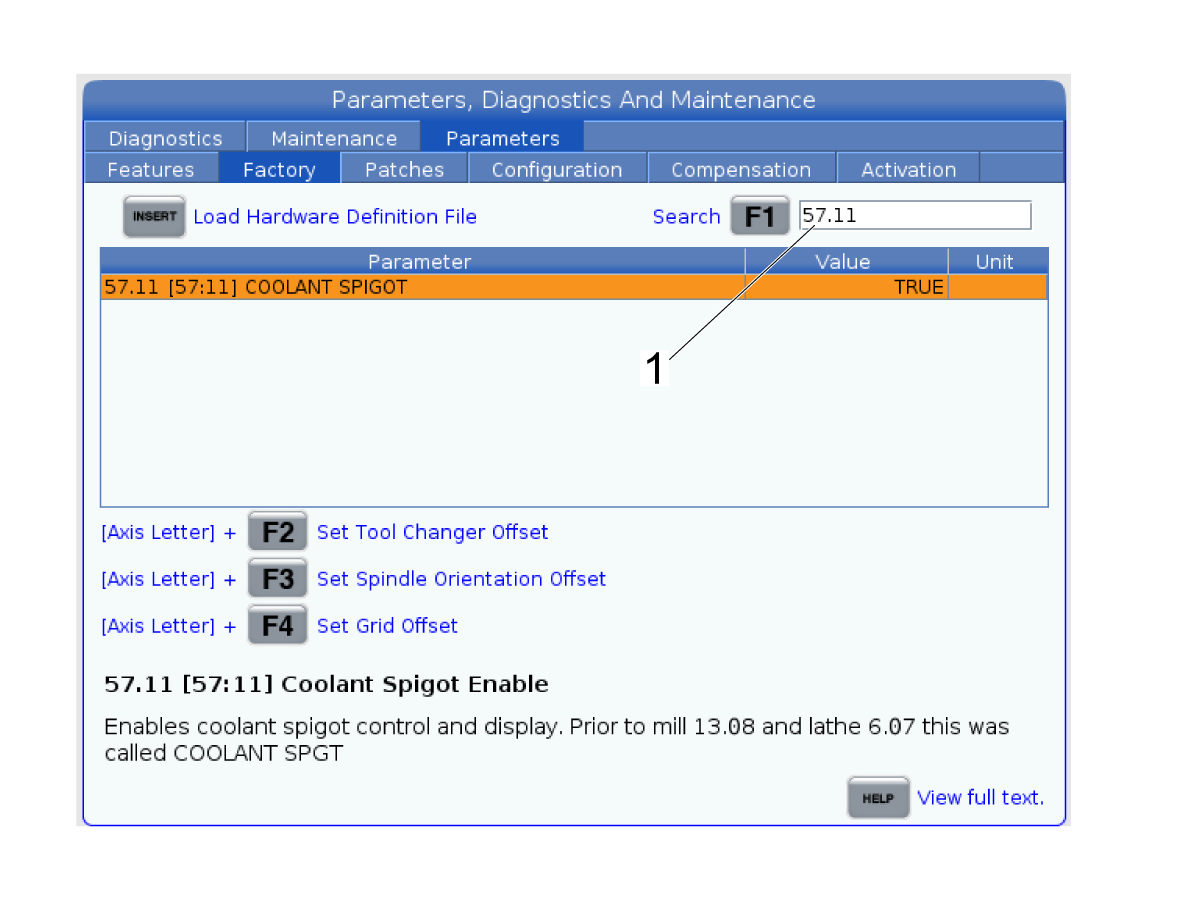
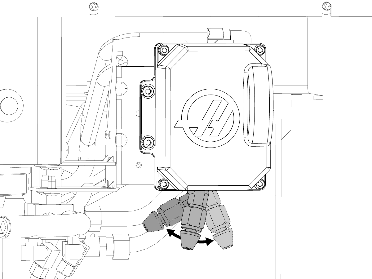
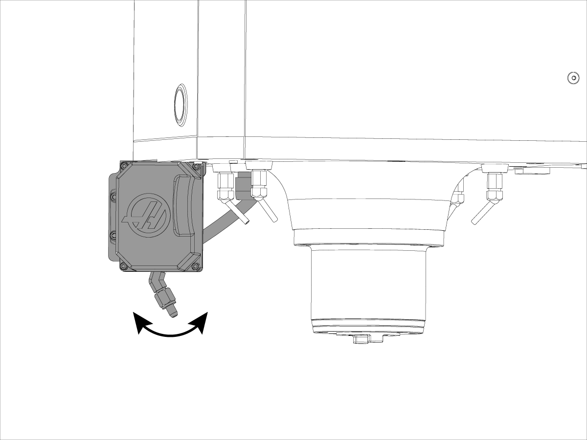
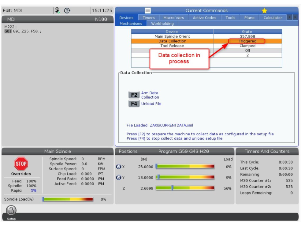
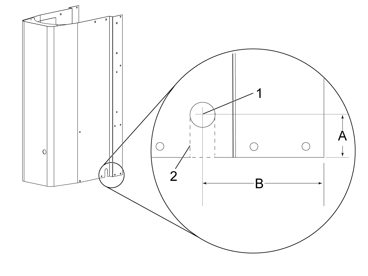
---spigot-positioning/new-and-ngc-pics/intro-(web).png)
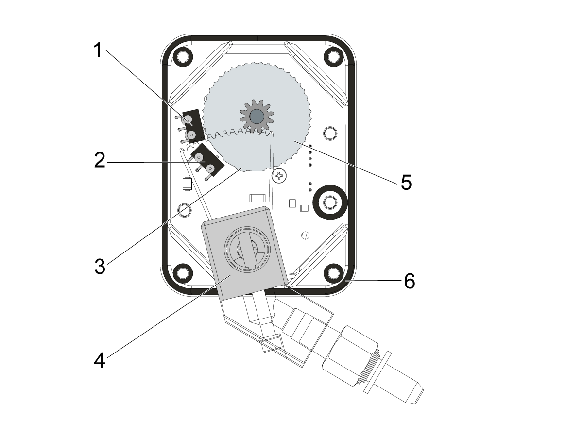
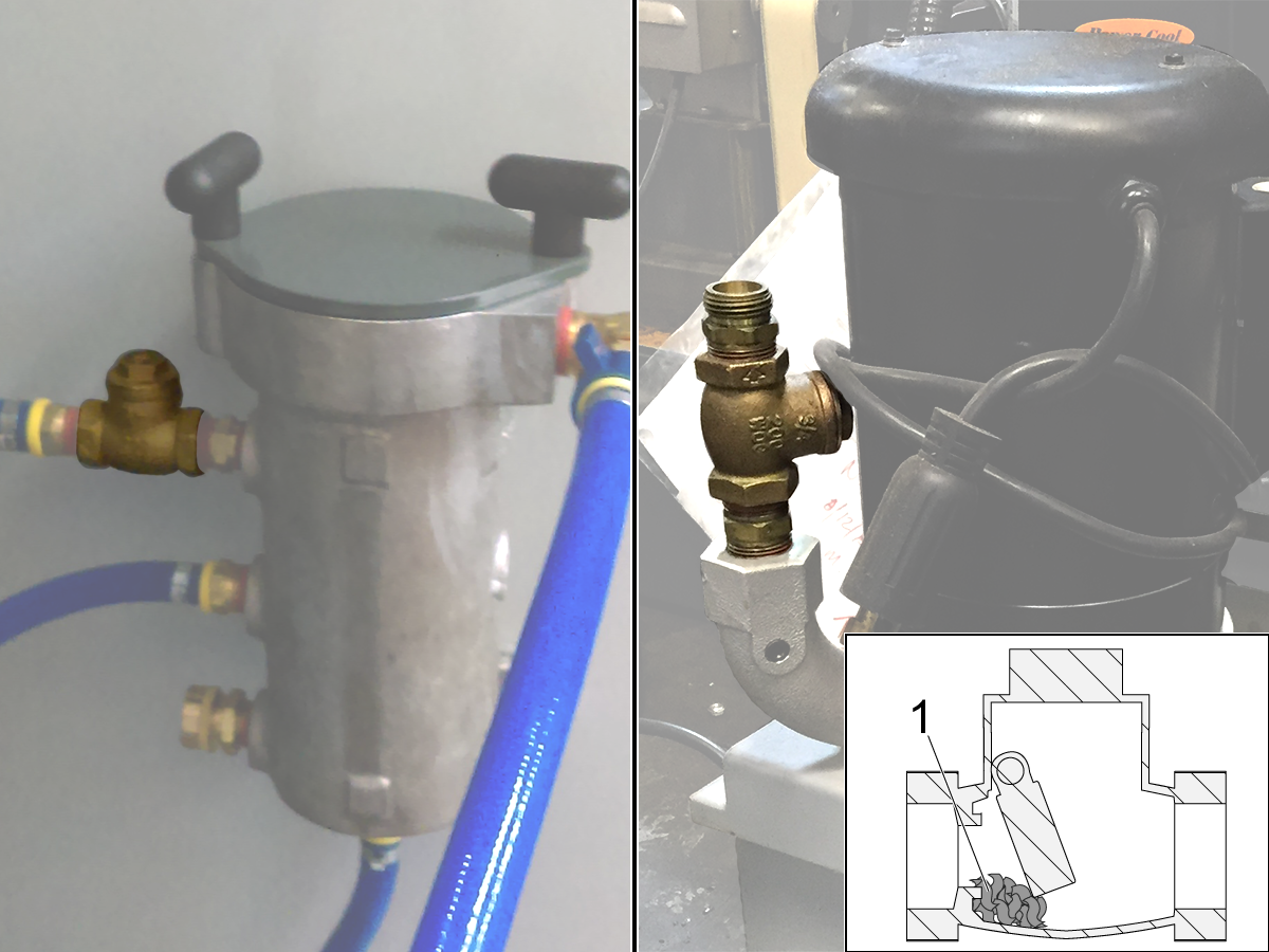
---spigot-positioning/Step_1_P_Cool_Valve.png)
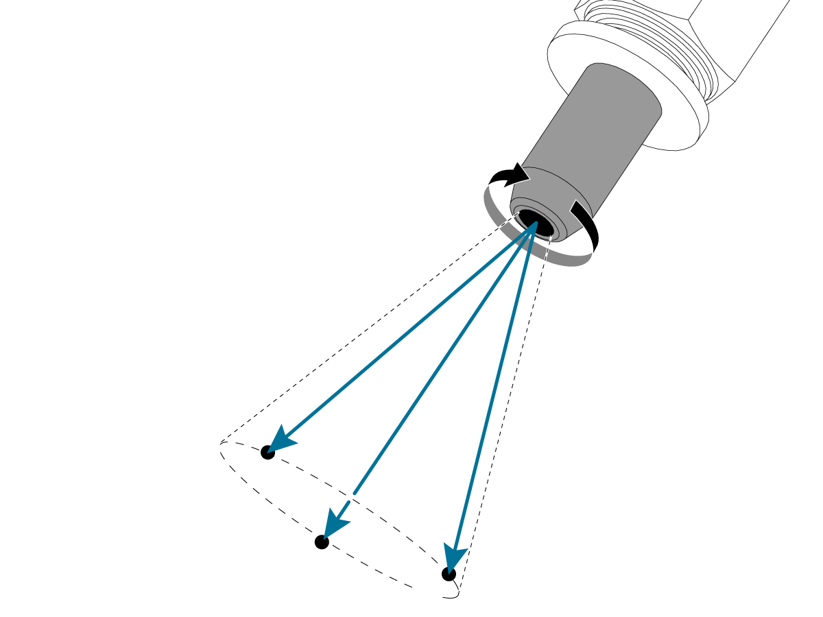
---spigot-positioning/new-and-ngc-pics/step-2.png)
---spigot-positioning/STEP_2_Press_Offset.png)
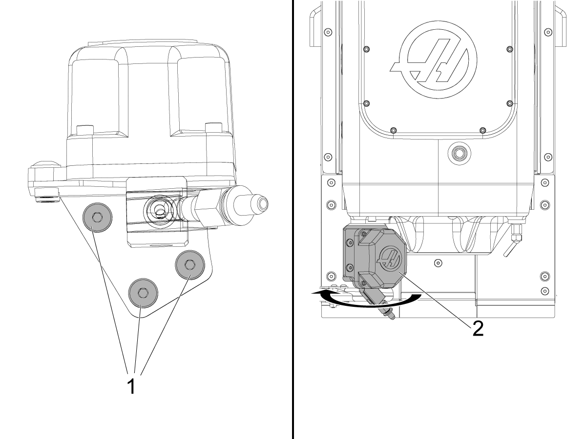
---spigot-positioning/new-and-ngc-pics/step-3-(web).png)
---spigot-positioning/new-and-ngc-pics/step-4.png)
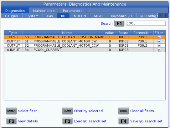
---spigot-positioning/STEP_4_CLNT_POS.png)
---spigot-positioning/new-and-ngc-pics/step-5.png)
---spigot-positioning/STEP_5_Select_Position.png)
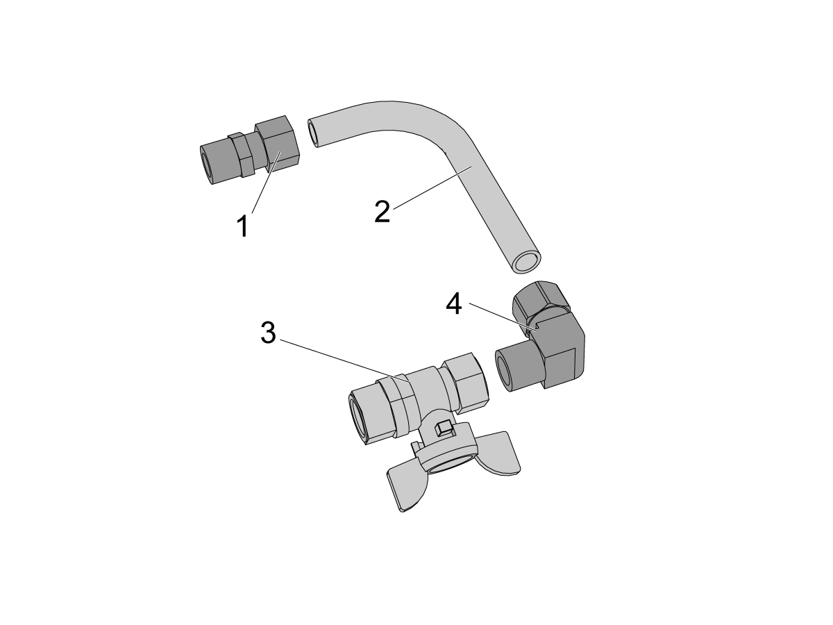
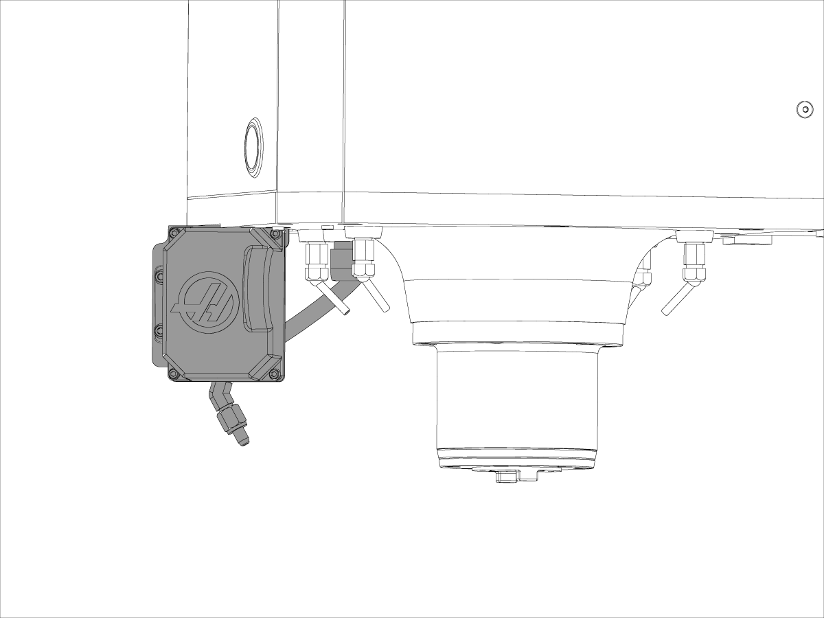
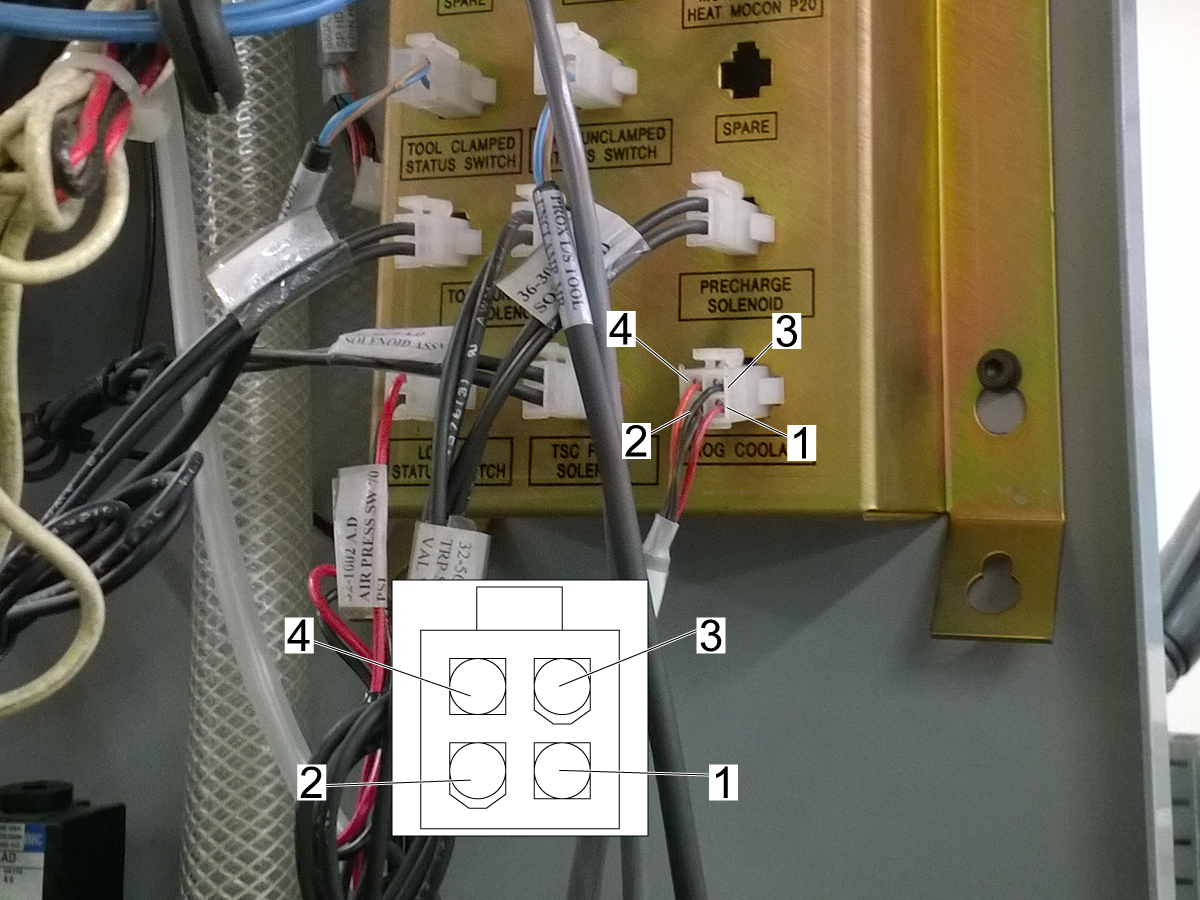
---replacement---vmc---ad0302/PCOOL_Overview.png)
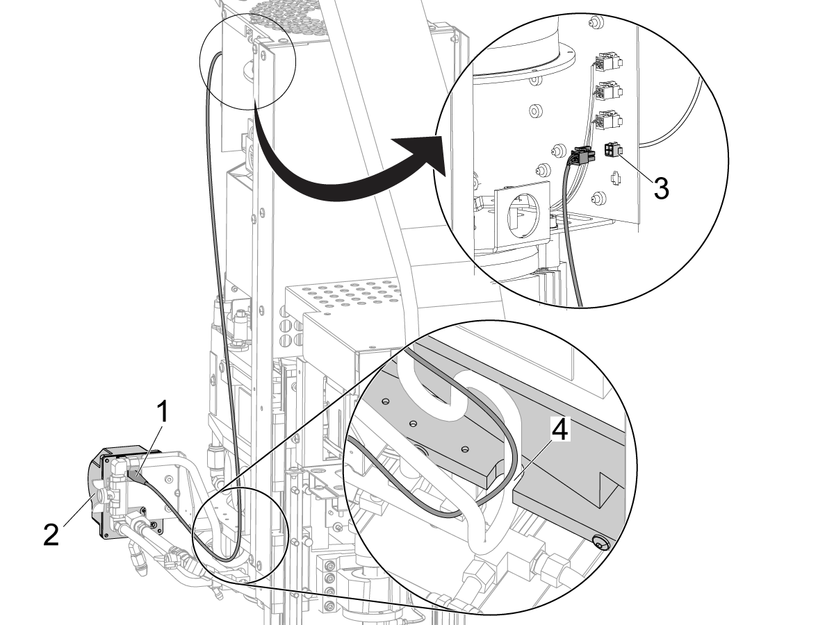
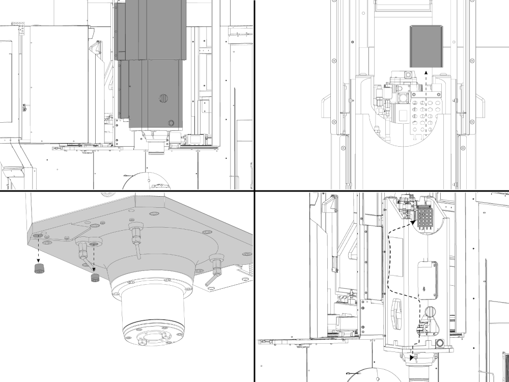
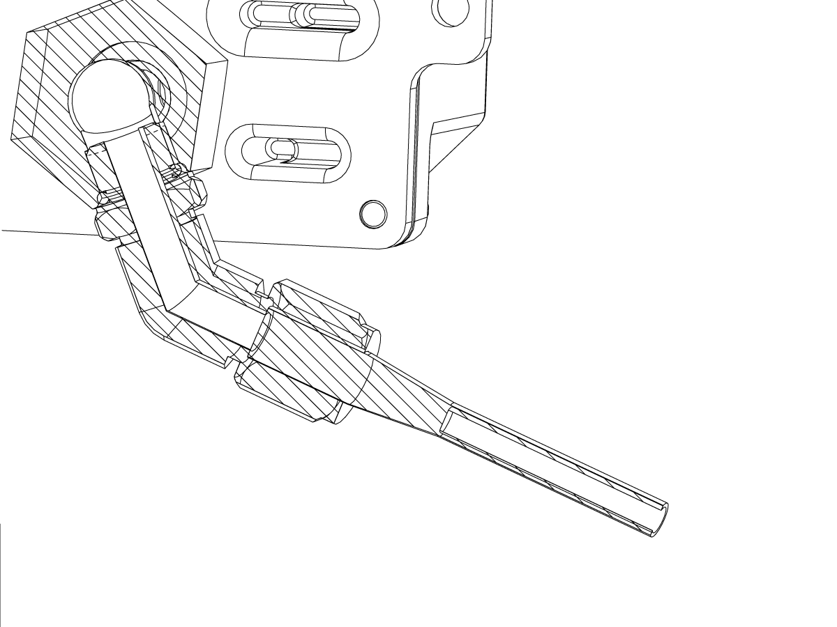
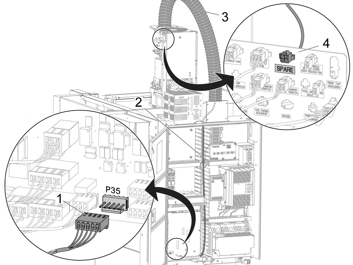
---replacement---vmc---ad0302/VMC_pcool_replacement_strain_relief_cable_overview2.png)
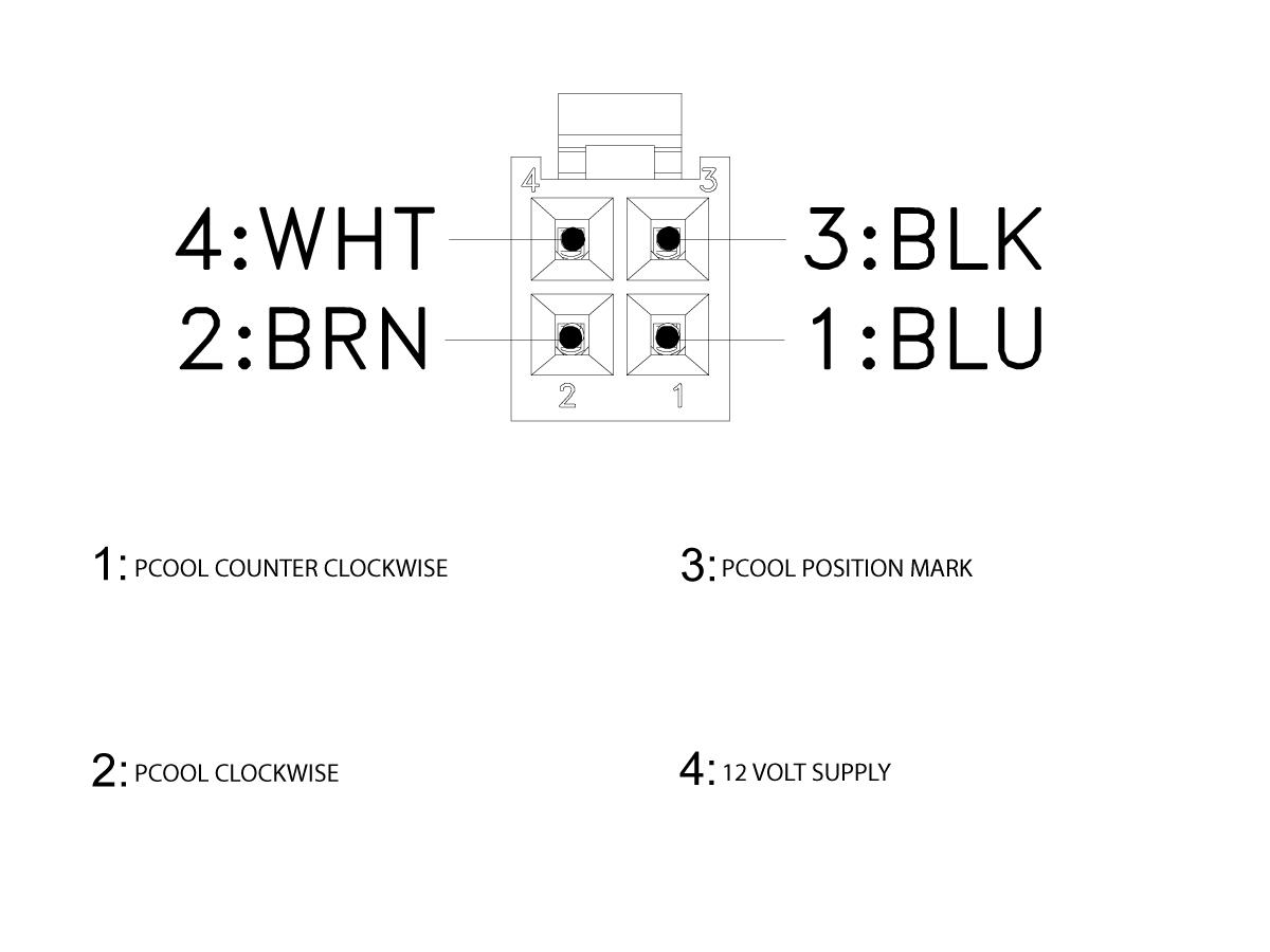
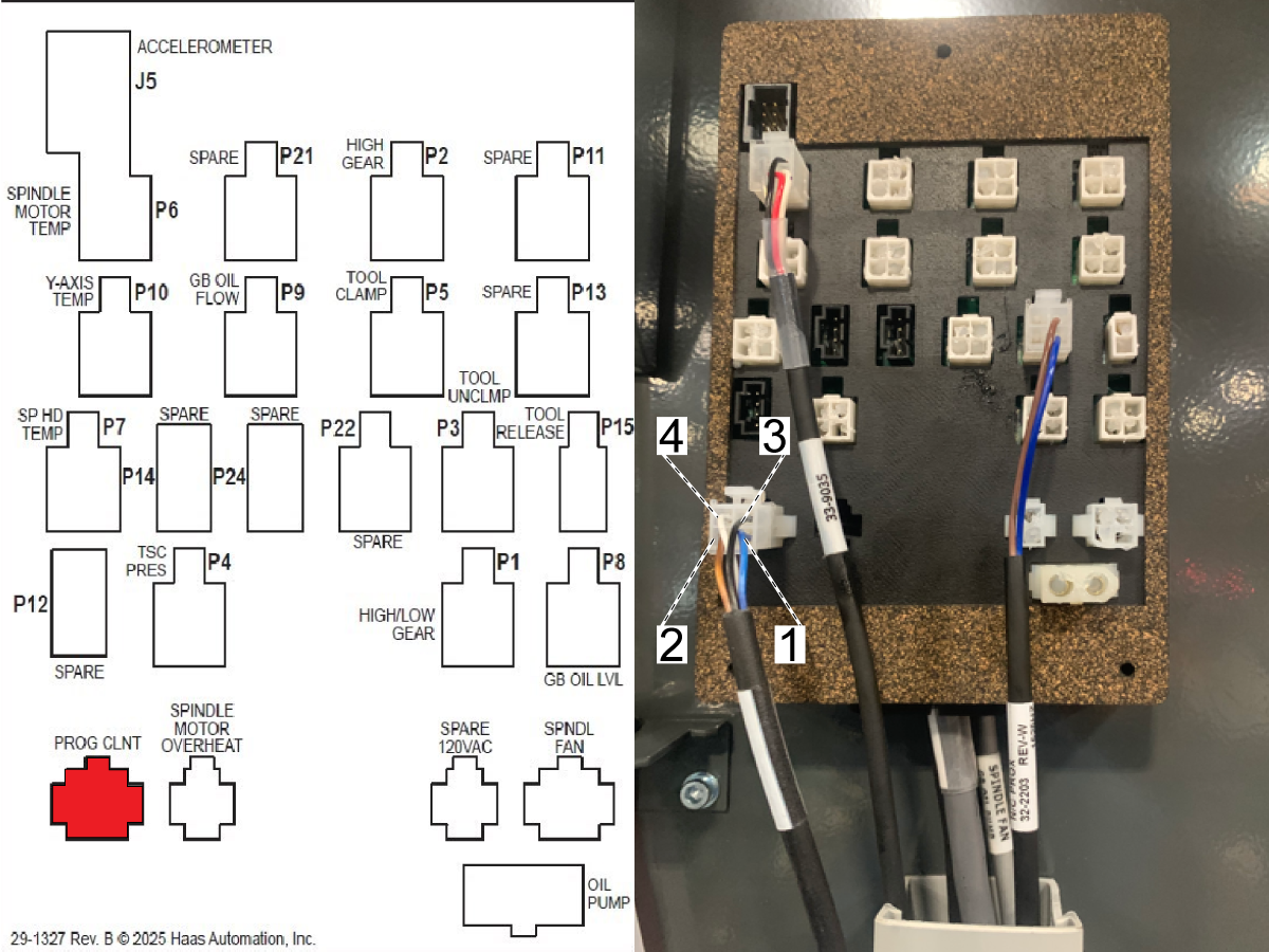
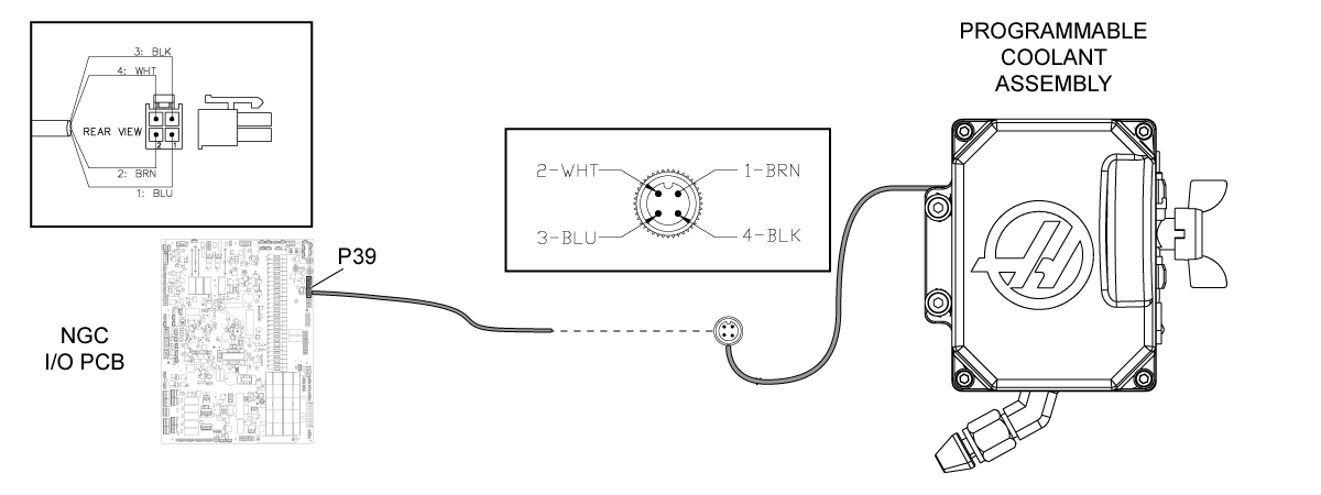
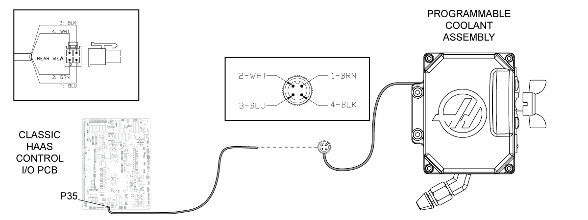
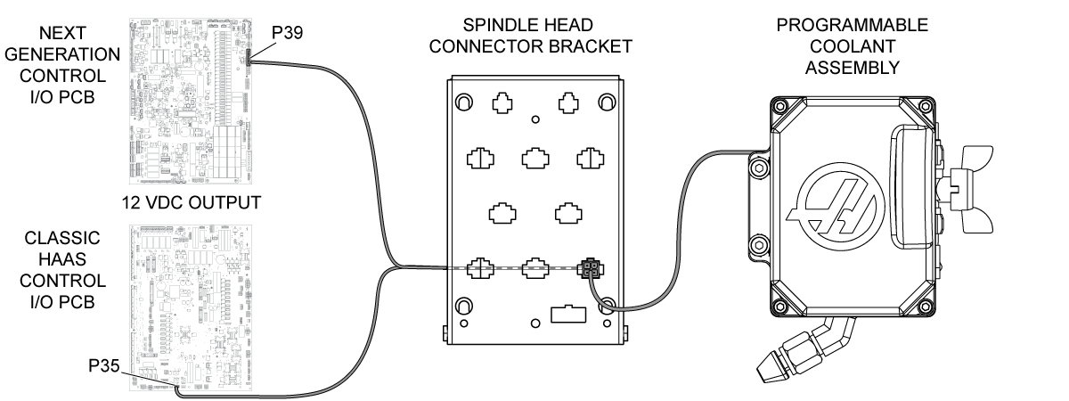
---replacement---vmc---ad0302/pcool_electrical_schematic_Rev_B_0.png)
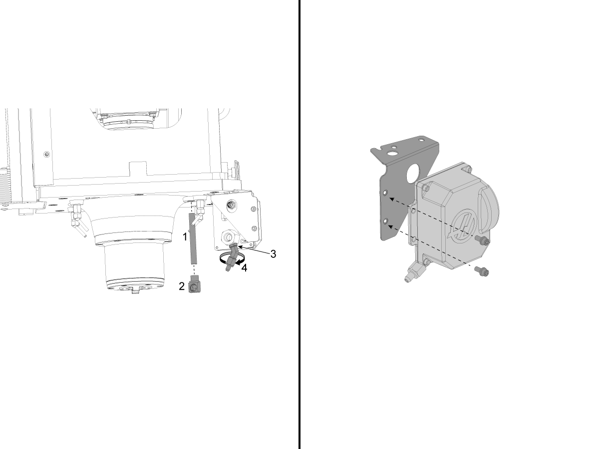
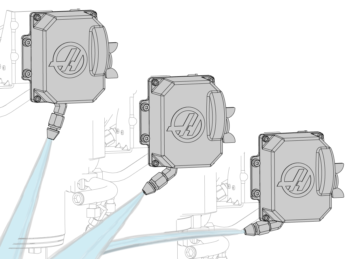
---replacement---vmc---ad0302/VMC_pcool_replacement_remove_old_assembly_Rev_C.png)
---replacement---vmc---ad0302/VMC_pcool_replacement_remove_M12_install_new_M12_Rev_E.png)
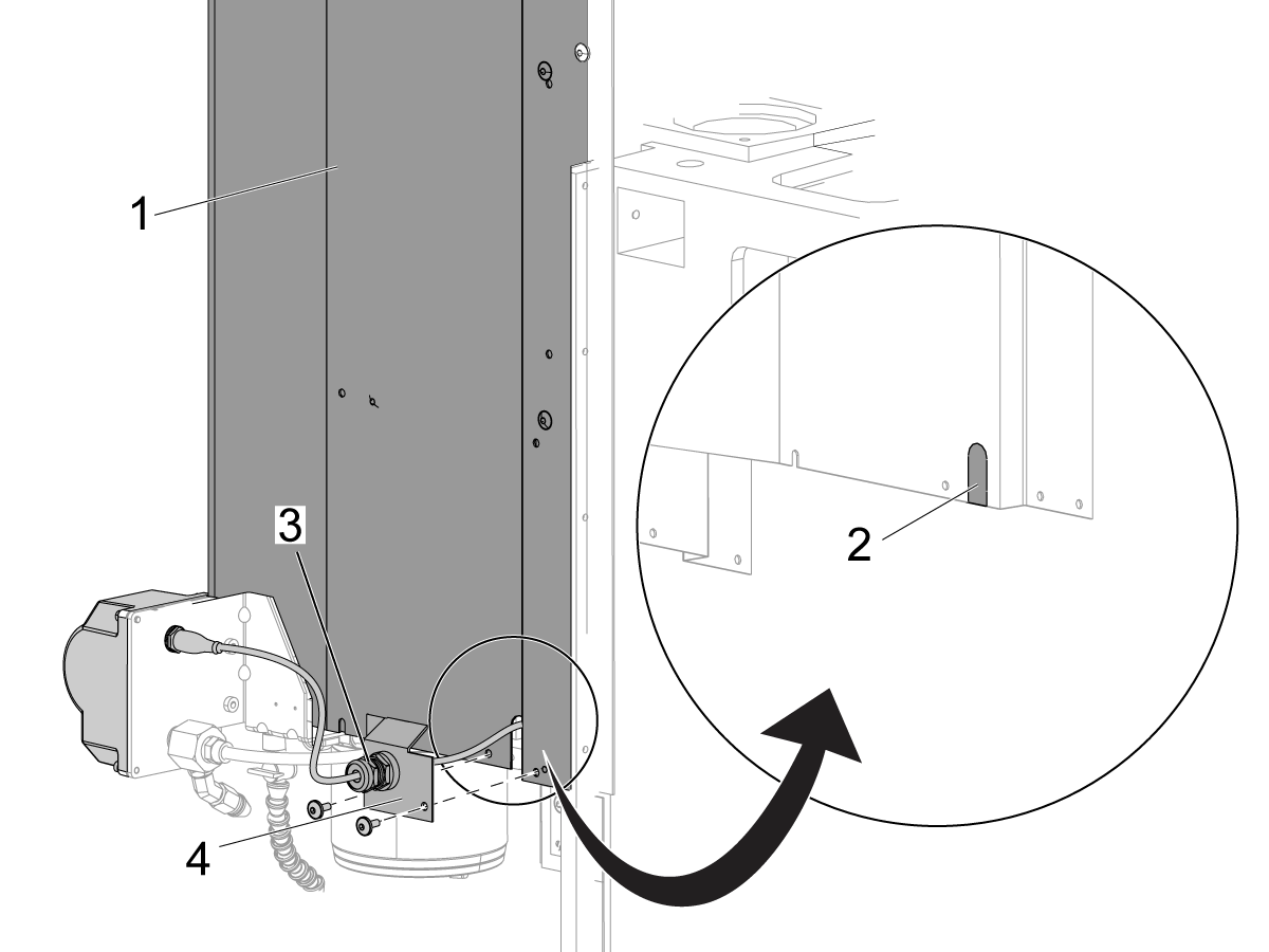
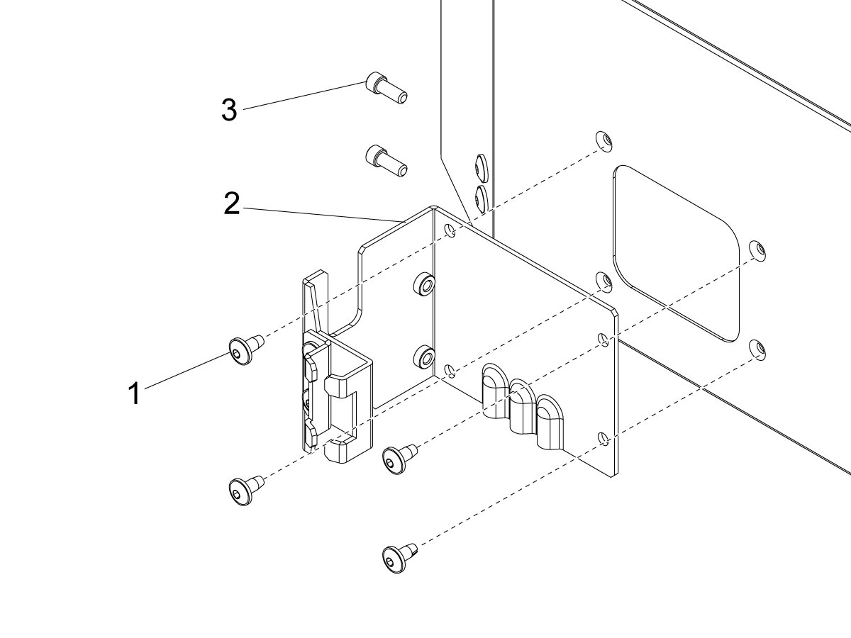
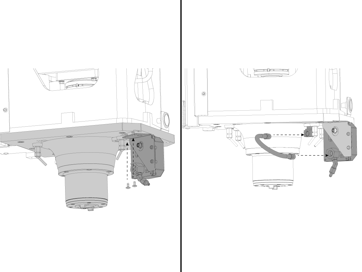
---replacement---vmc---ad0302/VMC_pcool_replacement_install_spindle_cover_cable_bracke_Rev_C.png)
.png)