My Haas Welcome,
!
Haas Tooling MyHaas/HaasConnect Sign In Register Haas Tooling MyHaas/HaasConnect Sign Out Welcome, My Machines Latest Activity My Quotes My Account My Users Sign Out
Find Your Distributor
  1. Select Language
    1. English
    2. Deutsch
    3. Español - ES
    4. Español - MX
    5. Français
    6. Italiano
    7. Português
    8. Český
    9. Dansk
    10. Nederlands
    11. Magyar
    12. Polski
    13. Svenska
    14. Türkçe
    15. 中文
    16. Suomi
    17. Norsk
    18. الإنجليزية
    19. български
    20. Hrvatski
    21. Ελληνικά
    22. Română
    23. Slovenský
    24. Slovenščina
    25. 한국어
    26. 日本語
    27. Українська
  • machines Main Menu
    • Vertical Mills
      Vertical Mills
      Vertical Mills View All
      • Vertical Mills
      • VF Series
      • Universal Machines
      • VR Series
      • VP-5 Prismatic
      • Pallet-Changing VMCs
      • Mini Mills
      • Mold Machines
      • High-Speed Drill Centers
      • Drill/Tap/ Mill Series
      • Toolroom Mills
      • Pocket Mill
      • Compact Mills
      • Gantry Series
      • SR Sheet Routers
      • Extra-Large VMC
      • Double-Column Mills
      • 3+2 Positioning Machines
    • Multi-Axis Solutions
      Multi-Axis Solutions
      Multi-Axis Solutions View All
      • Multi-Axis Solutions
      • Y-Axis Lathes
      • 5-Axis Mills
    • Lathes
      Lathes
      Lathes View All
      • Lathes
      • ST Series
      • Dual-Spindle
      • Box Way Series
      • Toolroom Lathes
      • Chucker Lathe
      • Pocket Lathe
      • Haas Bar Feeders
    • Horizontal Mills
      Horizontal Mills
      Horizontal Mills View All
      • Horizontal Mills
      • 50-Taper
      • 40-Taper
    • Rotaries & Indexers
      Rotaries & Indexers
      Rotaries & Indexers View All
      • Rotaries & Indexers
      • Rotary Tables
      • Indexers
      • 5-Axis Rotaries
      • Extra-Large Rotaries
    • Special Series
      Special Series
      Special Series View All
      • Special Series
      • EU_Series_Redirect
    • Automation Systems
      Automation Systems
      Automation Systems View All
      • Automation Systems
      • Mill Automation
      • Lathe Automation
      • Automatic Parts Loaders
      • Automation Models
    • Desktop Machines
      Desktop Machines
      Desktop Machines View All
      • Desktop Machines
      • Desktop Mill
      • Desktop Lathe
      • Control Simulator, Standard
      • Control Simulator, Premium
    • Shop Equipment
      Shop Equipment
      Shop Equipment View All
      • Shop Equipment
      • Knee Mill
      • Haas Manual Lathes
      • Haas Saws
    • Fabrication Machines
      Fabrication Machines
      Fabrication Machines View All
      • Fabrication Machines
      • Laser Cutting Machines
      • CNC Press Brakes
    • QUICK LINKS Special Series  Special Series 
      EU SERIES EU SERIES BUILD & PRICE | PRICE LIST BUILD & PRICE | PRICE LIST In-Stock Machines In-Stock Machines WHAT’S NEW WHAT’S NEW YOUR FIRST CNC YOUR FIRST CNC
      SHOPPING TOOLS
      • Build & Price a Haas
      • Price List
      • Available Inventory
      • CNCA Financing
      WANT TO TALK TO SOMEONE?

      A Haas Factory Outlet (HFO) can answer your questions, and walk you through your best options.

      CONTACT YOUR DISTRIBUTOR >
  • Options Main Menu
    • The Haas Control Value Option Packages
      Value Option Packages
      Value Option Packages View All
      • Value Option Packages
    • Product Image Spindles
      Spindles
      Spindles View All
      • Spindles
    • Product Image Tool Changers
      Tool Changers
      Tool Changers View All
      • Tool Changers
    • Product Image 4th- | 5th-Axis
      4th- | 5th-Axis
      4th- | 5th-Axis View All
      • 4th- | 5th-Axis
    • Product Image Turrets & Live Tooling
      Turrets & Live Tooling
      Turrets & Live Tooling View All
      • Turrets & Live Tooling
    • Product Image Probing
      Probing
      Probing View All
      • Probing
    • Haas Chip & Coolant Management Chip & Coolant Management
      Chip & Coolant Management
      Chip & Coolant Management View All
      • Chip & Coolant Management
    • The Haas Control The Haas Control
      The Haas Control
      The Haas Control View All
      • The Haas Control
    • Product Image Product Options
      Product Options
      Product Options View All
      • Product Options
    • Product Image Tooling & Fixturing
      Tooling & Fixturing
      Tooling & Fixturing View All
      • Tooling & Fixturing
    • Product Image Workholding
      Workholding
      Workholding View All
      • Workholding
    • Product Image 5-Axis Solutions
      5-Axis Solutions
      5-Axis Solutions View All
      • 5-Axis Solutions
      • 5 Easy Steps to 5-Axis
    • QUICK LINKS Special Series  Special Series 
      EU SERIES EU SERIES BUILD & PRICE | PRICE LIST BUILD & PRICE | PRICE LIST In-Stock Machines In-Stock Machines WHAT’S NEW WHAT’S NEW YOUR FIRST CNC YOUR FIRST CNC
      SHOPPING TOOLS
      • Build & Price a Haas
      • Price List
      • Available Inventory
      • CNCA Financing
      WANT TO TALK TO SOMEONE?

      A Haas Factory Outlet (HFO) can answer your questions, and walk you through your best options.

      CONTACT YOUR DISTRIBUTOR >
  • Why Haas Main Menu
      Discover the Haas Difference
    • Why Haas
    • MyHaas
    • Education Community
    • Industry 4.0
    • Haas Certification
    • Customer Testimonials
  • Service Main Menu
      Welcome to Haas Service
      SERVICE HOME Operator’s Manuals How-To Procedures Troubleshooting Guides Preventive Maintenance Haas Parts Haas Tooling Videos
  • Videos Main Menu
  • Main Menu
    • View All
    • View All
    • View All
    • View All
      • HTEC Curriculum Support
      • Haas Value Option Packages (VOP) Journey
    • View All
      • Haas 10 kg Cobot Package
      • Cobot Kits
      • DC-1 Drill Center
      • CNC Sales News
      • Do More With Your Haas
    • View All
    • View All
      • contact-us-test
      • 4 - AUTOMATION SYSTEMS
      • Carousel-V2
      • expert test
      • Demo_Day_Trident-test
      • Link Test
      • image-sale-tag-test
      • article-list-test
      • Haas 25 kg Robot Package
      • test-algolia-page
    • View All
    • View All
    • View All
    • View All
      • calc-test
    • View All
    • QUICK LINKS Special Series  Special Series 
      EU SERIES EU SERIES BUILD & PRICE | PRICE LIST BUILD & PRICE | PRICE LIST In-Stock Machines In-Stock Machines WHAT’S NEW WHAT’S NEW YOUR FIRST CNC YOUR FIRST CNC
      SHOPPING TOOLS
      • Build & Price a Haas
      • Price List
      • Available Inventory
      • CNCA Financing
      WANT TO TALK TO SOMEONE?

      A Haas Factory Outlet (HFO) can answer your questions, and walk you through your best options.

      CONTACT YOUR DISTRIBUTOR >
  • Haas Tooling Main Menu
  • Haas Service Parts Main Menu

My Haas Welcome,
!
Haas Tooling MyHaas/HaasConnect Sign In Register Haas Tooling MyHaas/HaasConnect Sign Out Welcome, My Machines Latest Activity My Quotes My Account My Users Sign Out
Find Your Distributor
  1. Select Language
    1. English
    2. Deutsch
    3. Español - ES
    4. Español - MX
    5. Français
    6. Italiano
    7. Português
    8. Český
    9. Dansk
    10. Nederlands
    11. Magyar
    12. Polski
    13. Svenska
    14. Türkçe
    15. 中文
    16. Suomi
    17. Norsk
    18. الإنجليزية
    19. български
    20. Hrvatski
    21. Ελληνικά
    22. Română
    23. Slovenský
    24. Slovenščina
    25. 한국어
    26. 日本語
    27. Українська
×

Search Results

Web Pages

Images

    • <
    • 1
    • >

4 - Oil Skimmer

Chip Removal and Coolant - Service Manual


  • 1 - Chip and Coolant - Introduction
  • 2 - Auxiliary Coolant Filter
  • 3 - Single-Stage Flood Coolant
  • 4 - Oil Skimmer
  • 5 - Programmable Coolant
  • 6 - Chip Auger
  • 7 - Coolant Chiller
  • 8 - Chip Conveyor - Overview
  • 8a - Standard Belt Chip Conveyor
  • 8c - CDF Chip Conveyor
  • 9 - Chip Conveyor - VMC
  • 10 - Chip Conveyor - UMC
  • 11 - Chip Conveyor - Lathe
  • 12 - Coolant Refill
  • 13 - High Pressure Flood Coolant
  • 14 - Through-Spindle Coolant
  • 15 - Through-Tool Air Blast
  • 15a - Through-Tool Oil Mist
  • 16 - Haas Chip Lift
  • 17 - Mist Condenser
  • 18 - Coolant Level Float Sensor
  • 19 - Mini Conveyor
  • 20 - Coolant VFD
  • 21 - Coolant Sanitizer
  • 22 - Chip Separator
  • 23 - Chip Tray Strainer
  • 24 - Multi-Stage Flood Coolant
  • 25 - Coolant Cart

Go To :

  • 4.1 Haas Oil Skimmer - Installation
  • 4.2 Haas Oil Skimmer - Maintenance
  • 4.3 Haas Oil Skimmer - Troubleshooting
  • 4.4 Zebra Oil Skimmer - Installation
  • 4.5 Zebra Oil Skimmer - Maintenance
  • 4.6 Zebra Oil Skimmer - Troubleshooting

4.1 Haas Oil Skimmer - Installation

Recently Updated

Haas Oil Skimmer - Installation


AD0480

Rev C - 10/2025

Introduction

This procedure tells you how to install the Haas Oil Skimmer system. The Oil Skimmer does these functions:

  • Automatically removes tramp oil. This decreases bacteria and helps to keep the coolant clean
  • Constant rotation removes oil from the surface of the coolant and deposits it into an external collection container.
  • Starts and stops easily with the toggle switch on the side of the unit. You can also add an electrical timer to automatically start and stop the Oil Skimmer.

For information on maintenance, refer to the Haas Oil Skimmer - Maintenance procedure.

For information on troubleshooting, refer to the Haas Oil Skimmer - Troubleshooting Guide. 

This procedure applies to the following service kits:

  • 93-1000195: OIL SKIMMER HAAS
  • 93-1001137: OIL SKIMMER FIELD INSTALL KIT ST-10/15
  • 93-5046: BRACKET OIL SKIMMER DC-1

Note: 93-5046 is a bracket to help the oil skimmer mount to the coolant tank on DC style machines. 93-5046 needs to be ordered in addition to 93-1000195 when installing the oil skimmer option on a DC-1, DC-2, or DC-4.

Machine Compatibility

  • You can install the Oil Skimmer on machines that have an external 55-gallon (208 L) or 95-gallon (360 L) coolant tank. 
  • UMC-400/SS with a 45-gallon (170 L) coolant tank.
  • SMM/MM/MM-EDU with a 45-gallon (170 L) coolant tank.
  • SMM2/MM2 with a 45-gallon (170 L) coolant tank.
  • Machines ST-10/15/L Machines shipped before 5/14/25: Requires OIL SKIMMER MOUNT BRKT EXT from the Oil Skimmer Mount Bracket Kit (P/N: 93-1001137). ST-10/15/L HPC option is not compatible with the Oil Skimmer.
  • Machines ST-10/15/L Machines shipped after 5/14/25: OIL SKIMMER MOUNT BRKT EXT included. Oil Skimmer Mount Bracket Kit (P/N: 93-1001137) not required. ST-10/15/L HPC option is not compatible with the Oil Skimmer.

The coolant tanks in the list below have a hole and a slot in the coolant tank cover for the Oil Skimmer:

  • 55-gallon (208L) coolant tanks made after May, 2019.
  • 95-gallon (360L) coolant tanks made after Feb, 2019.

For all other machines, you must use the Tank Cover Template to make the hole and the slot in the coolant tank cover.

For all machines made before October 2014, you must use the Enclosure Apron Template to makes holes in the enclosure apron for the female connector on the 25 FT EXTENSION CABLE [B].

 Note: This procedure shows a vertical machine. The installation on lathes and horizontal machines is similar.

Tools Required
  • Drill
  • Jigsaw
  • Drill Bit - 5/32" (0.156")
  • Hole Saw - 1.75"

Templates

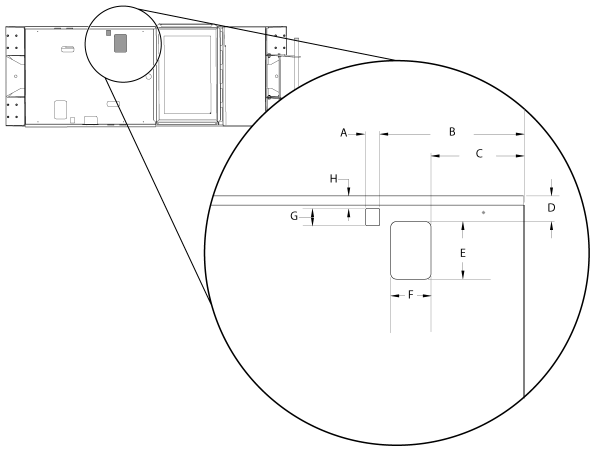
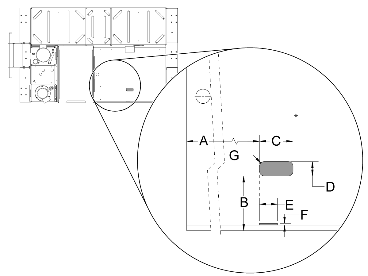
Tank Cover -Template

Use this template to make the hole and the slot in the coolant tank cover.

Cut the hole and slot on the left or right side of the cover. Choose the side for your machine that gives you access the Oil Skimmer.

On the top of the cover for the coolant tank, measure and mark the dimensions o the holes.

  • A - 1.20" (3 cm).
  • B - 12.50" (32 cm).
  • C - 8.10" (21 cm).
  • D - 2.20" (6 cm).
  • E - 5.00" (13 cm).
  • F - 3.50" (9 cm).
  • G - 1.50" (4 cm).
  • H - 1.10" (3 cm).

Cut and de-burr the hole and the slot.

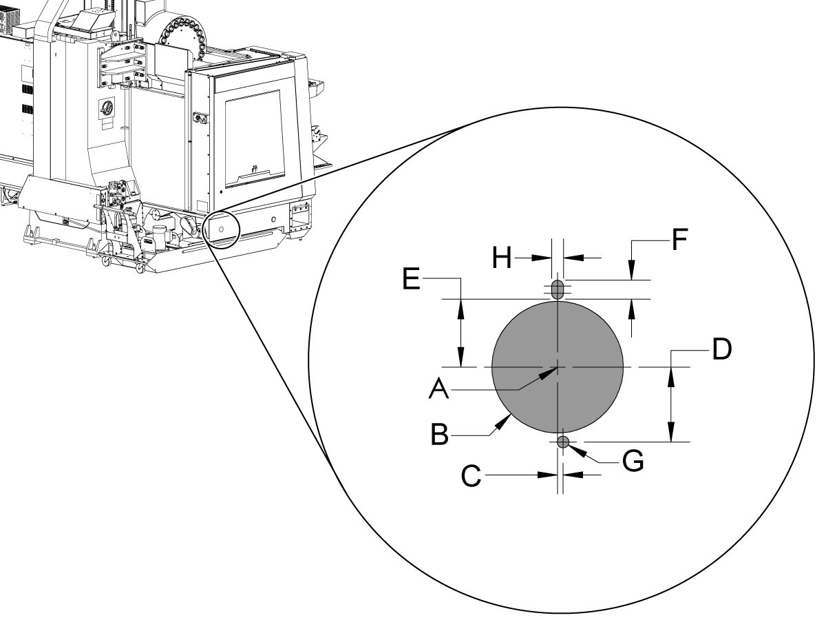
Enclosure Apron - Template

For all machines made before October 2014, you must use this template to make (3) holes in the enclosure apron for the female connector on the 25 FT EXTENSION CABLE.

Choose a location in the apron that is near the Oil Skimmer. Put a mark in the apron [A] for the center of the hole.

Measure and mark these dimensions for the holes:

  • B - Ø1.75" (4.4 cm).
  • C - 0.07" (0.1 cm).
  • D - 1.00" (2.5 cm).
  • E - 0.90" (2.3 cm).
  • F - 0.25" (0.6 cm).
  • G - Ø0.156" (0.4 cm).
  • H - 0.156" (0.4 cm).

Cut and de-burr the (3) holes.

Oil Skimmer Installation

1

Note: This step is for DC-Series machines only.

Install OIL SKIMMER BRACKET [1] onto the coolant tank edge before hanging the OIL SKIMMER BASE [2]. 

Hang the OIL SKIMMER BASE [2] over the OIL SKIMMER BRACKET [1].

2

 Note: This step is for ST-10/15/L machines only.

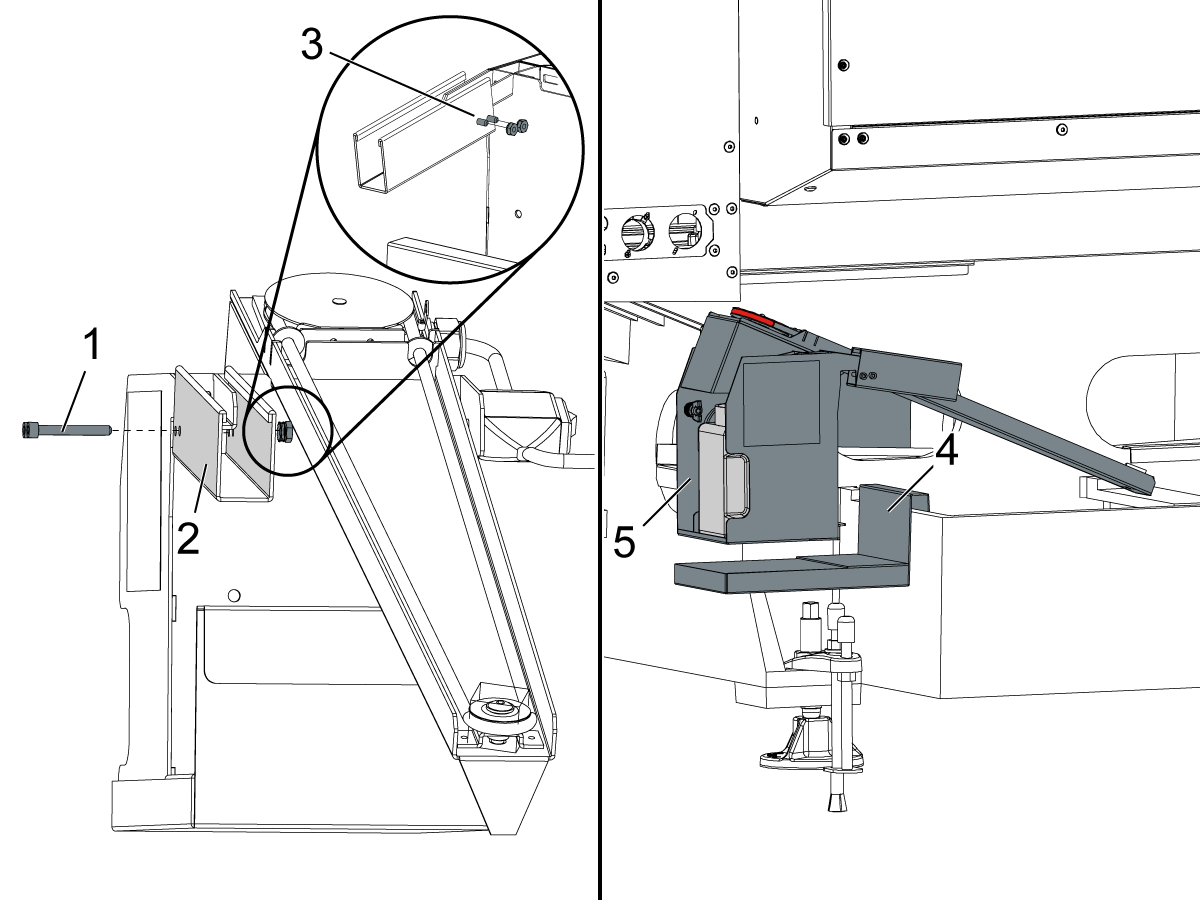
 Note: For machines that were purchased with the oil skimmer option, the Mount Bracket Extension and Oil Skimmer Bracket must be adjusted to match the images.

Fit the OIL SKIMMER MOUNT BRKT EXT [1] to the oil skimmer snout.

Use the OIL SKIMMER MOUNT BRKT EXT [1] as a guide to mark the holes [3] to the oil skimmer snout [2]. 

Remove the OIL SKIMMER MOUNT BRKT EXT [1] and use a #7 drill to make .201" (5.105mm) diameter holes with the drill through both sides of the oil skimmer snout. 

 Note: This step is for ST-10/15/L machines only.

Install the (2) x SHCS 10-32 x 1 1/2 through the OIL SKIMMER MOUNT BRKT EXT [2]. Install the (2) x 10-32 HEX W/ LCKWASHER [3].

Install OIL SKIMMER BRACKET [4] onto the coolant tank edge before hanging the OIL SKIMMER BASE [5]. 

Hang the OIL SKIMMER BASE [5] over the OIL SKIMMER BRACKET [4].

3

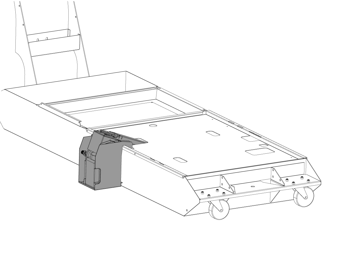
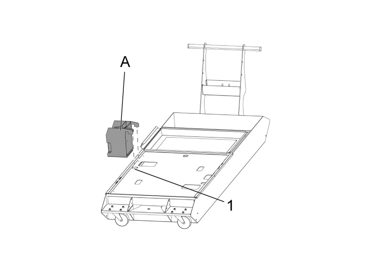
Hang the OIL SKIMMER BASE [A] from the Coolant Tank with the hanging hooks engaged onto the Coolant Tank Lid [1].  The horizontal surface of the hanging hooks should be flat on the top of the Coolant Tank Lid edge.


4

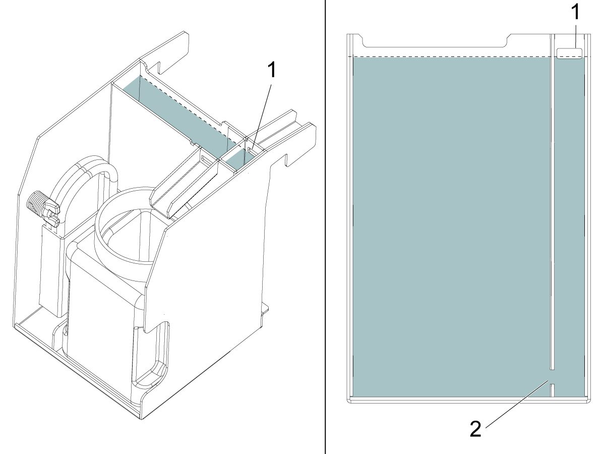
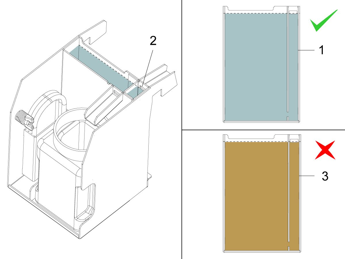
Fill the Oil Skimmer Chambers with clean coolant up to the drain [1] facing the coolant tank.

NOTE: The two chambers are connected with a slot at the bottom [2]. Make sure both chambers are filled. 

5

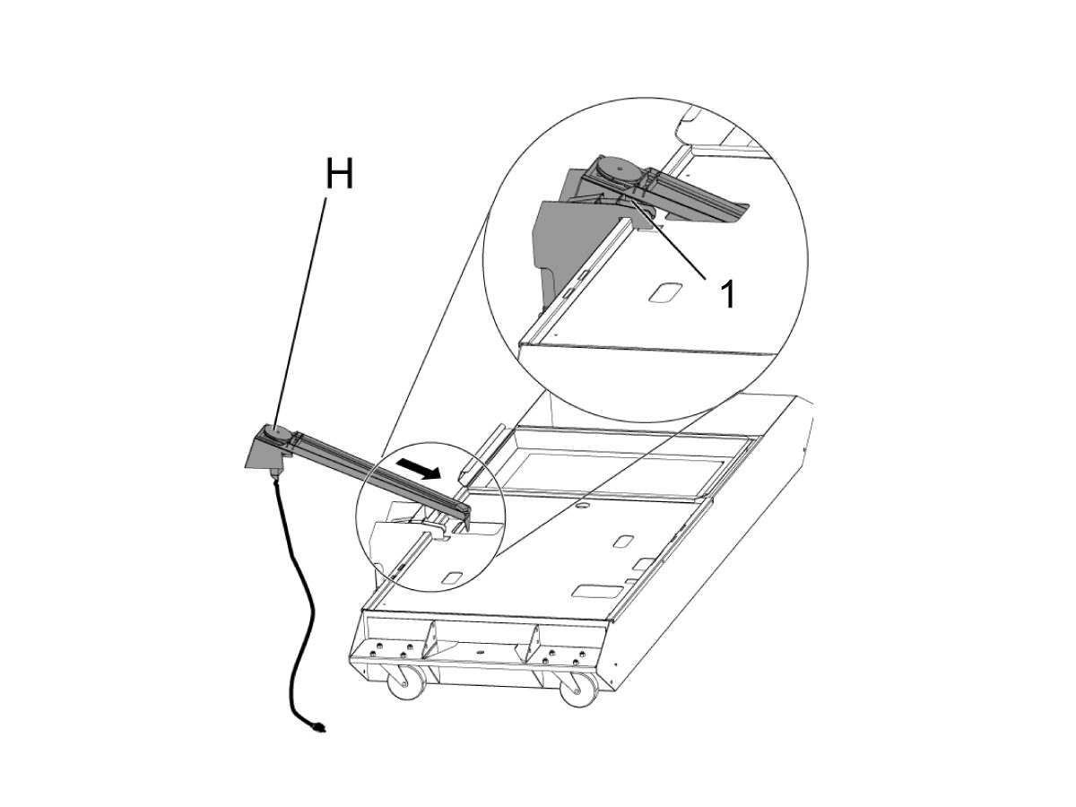
Install the OIL SKIMMER TOP ASSEMBLY [H] by positioning the narrow end of the Oil Skimmer into the Coolant Tank lid opening and then fitting the motor end onto the base engaging the alignment slots [1].

6

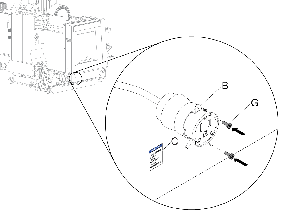
Attach the female connector on the 25 FT EXTENSION CABLE [B] to the enclosure apron. Use the (2) BOLTS [G].

Apply the DECAL [C] to the enclosure apron.

7

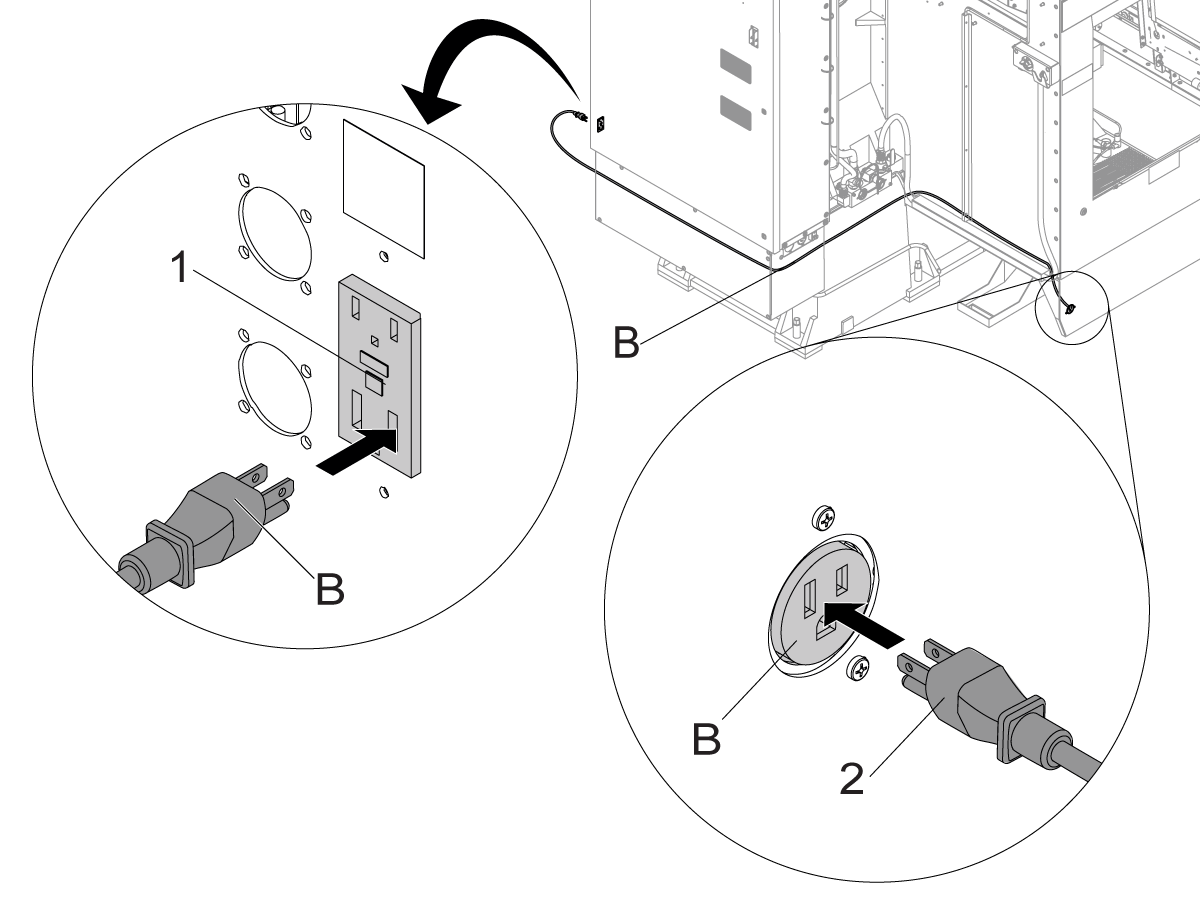
Connect the 25 FT EXTENSION CABLE [B] to the GFCI outlet [1] on the control cabinet.

Use the CABLE TIES [D], the CLAMPS [E], and the MOUNTS [F] as necessary to route the cable.

Connect the power cable [2] for the Oil Skimmer to the female connector on the 25 FT EXTENSION CABLE [B] in the enclosure apron.

Oil Skimmer Operation

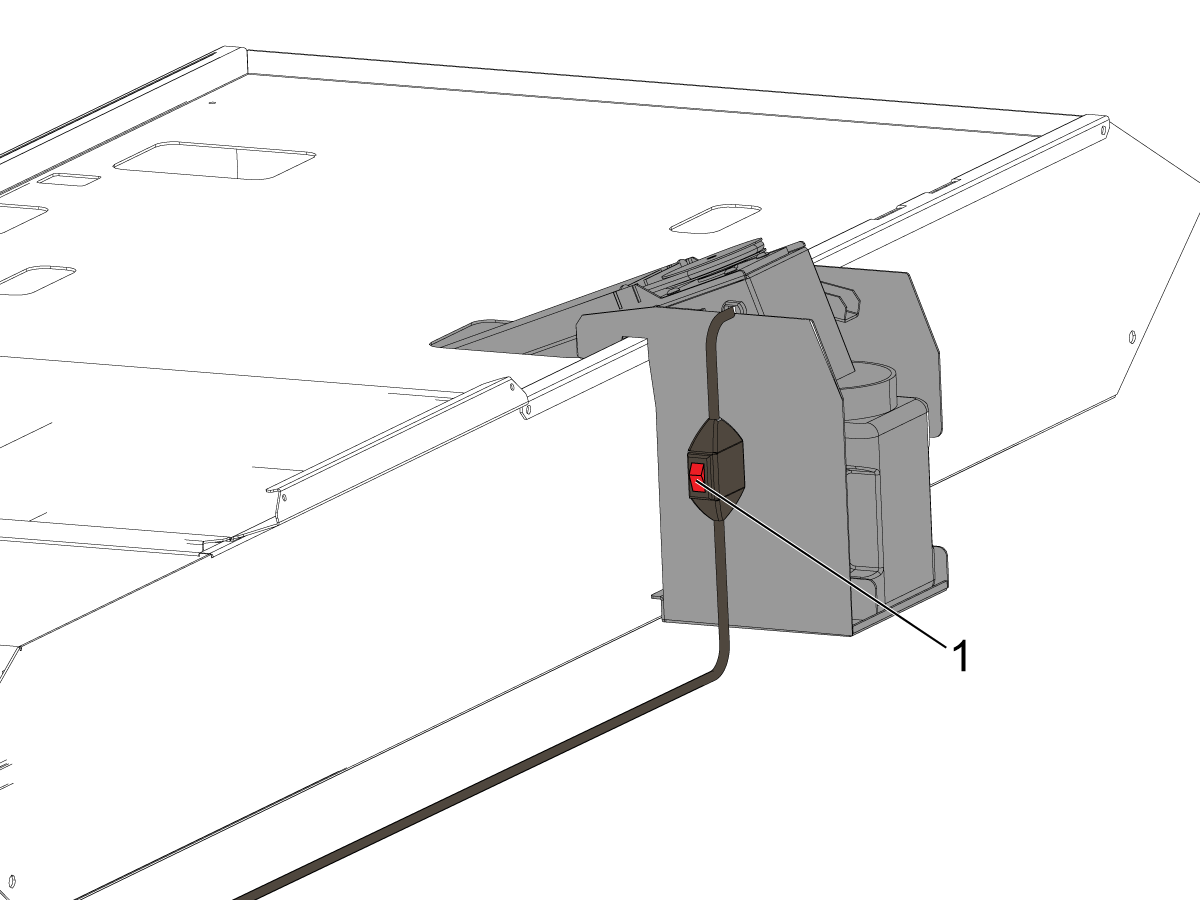
Turn the switch [1] to the on position.

Empty the Oil Container when full.

The oil skimmer is equipped with replacement scraper rings and replacement skimmer belt. Replace these components periodically based on their condition.

Overtime, coolant will get dirty. Replace with clean coolant periodically based on its condition. 

4.2 Haas Oil Skimmer - Maintenance

Recently Updated

Haas Oil Skimmer - Maintenance


AD0481

Revision A - 8/2025

Maintenance Video

The following service video shows you how to do maintenance on the Haas Oil Skimmer product.

Note: This service video is for reference only and does not replace the written procedure.

Introduction

This procedure will show you how to do maintenance on the Haas Oil Skimmer product.

 NOTE: Chips or other debris may be collecting on the oil skimmer scraper which adds additional stress to the motor which may result in premature failure. Remove all debris or chips from the scraper. 

For instructions on how to install the Haas Oil Skimmer please take a look at HAAS OIL SKIMMER - INSTALLATION

Replacement

1

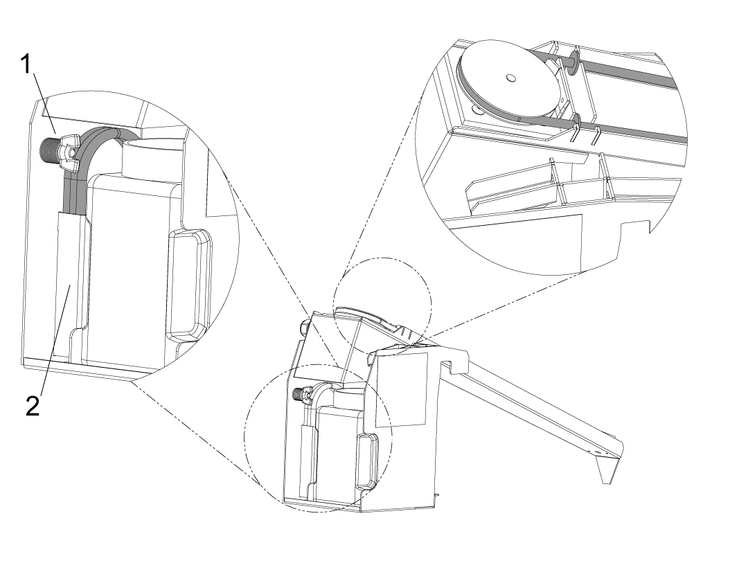
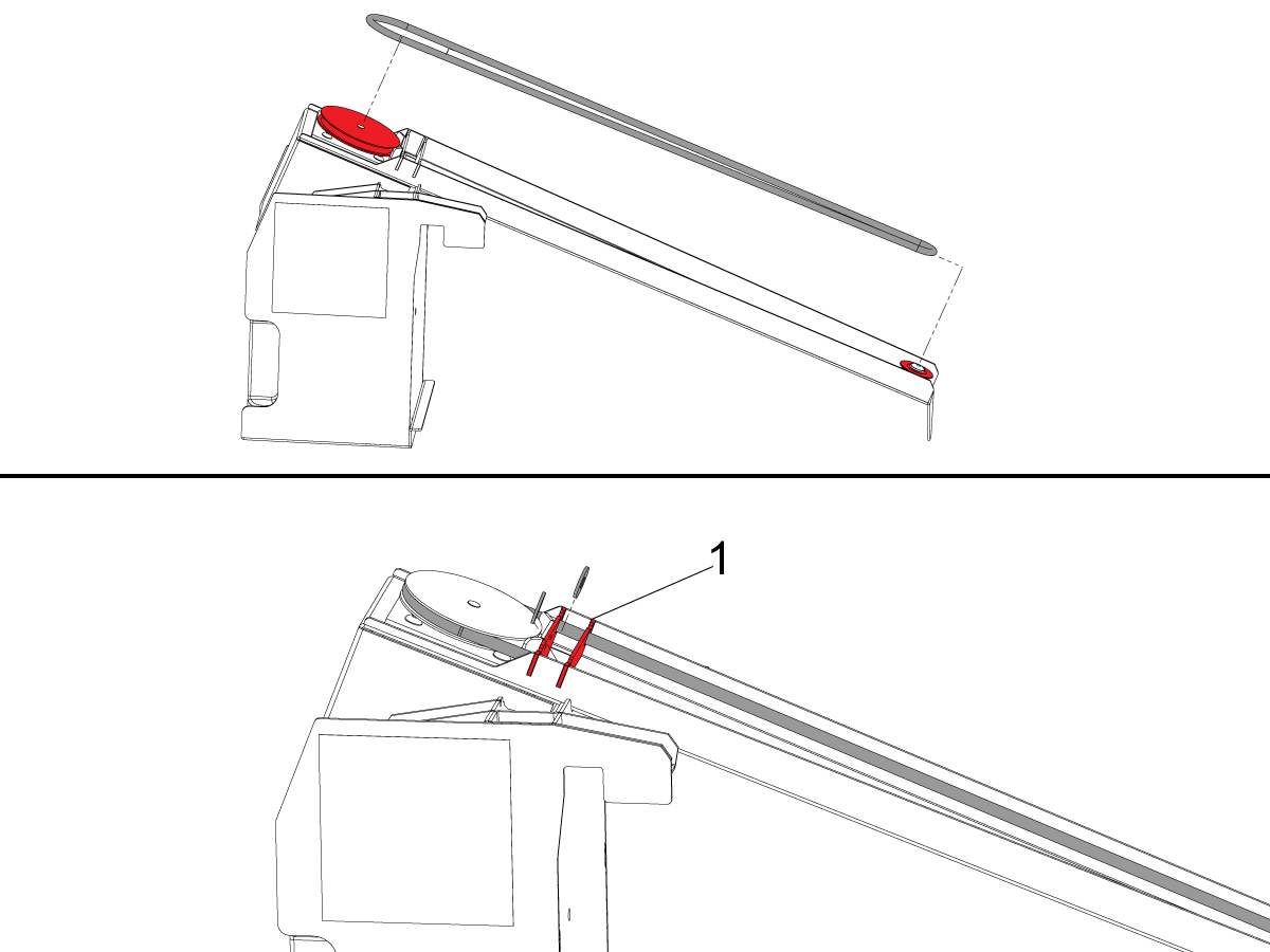
Identify where the replacement components and their corresponding storage locations are.

Place excess scrapers on holder [1] and held with wing nut.

Extra O-rings should be placed in holder [2].


2

When replacing the O-ring, make sure the O-ring is not twisted and in between the grooves of both rollers. 

While installing the O-ring install the scrapers, make sure the scrapers are in the slot highlighted [1]. 

Once completed run the oil skimmer and ensure it runs properly. 


3

When:

  • Coolant level is below the drain [2] 
  • Coolant gets dirty and appears gold [3]

Clean thoroughly with water and refill the Oil Skimmer Chambers with clean coolant [1] up to the drain [2] facing the coolant tank. 

4.3 Haas Oil Skimmer - Troubleshooting

Recently Updated

Haas Oil Skimmer - Troubleshooting Guide


TG0080

Revision D - 02/2026

Introduction

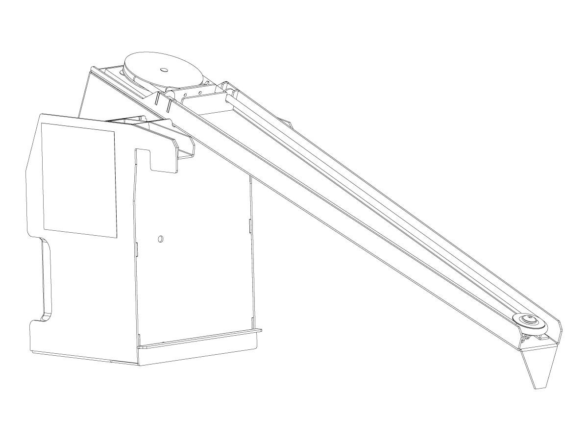
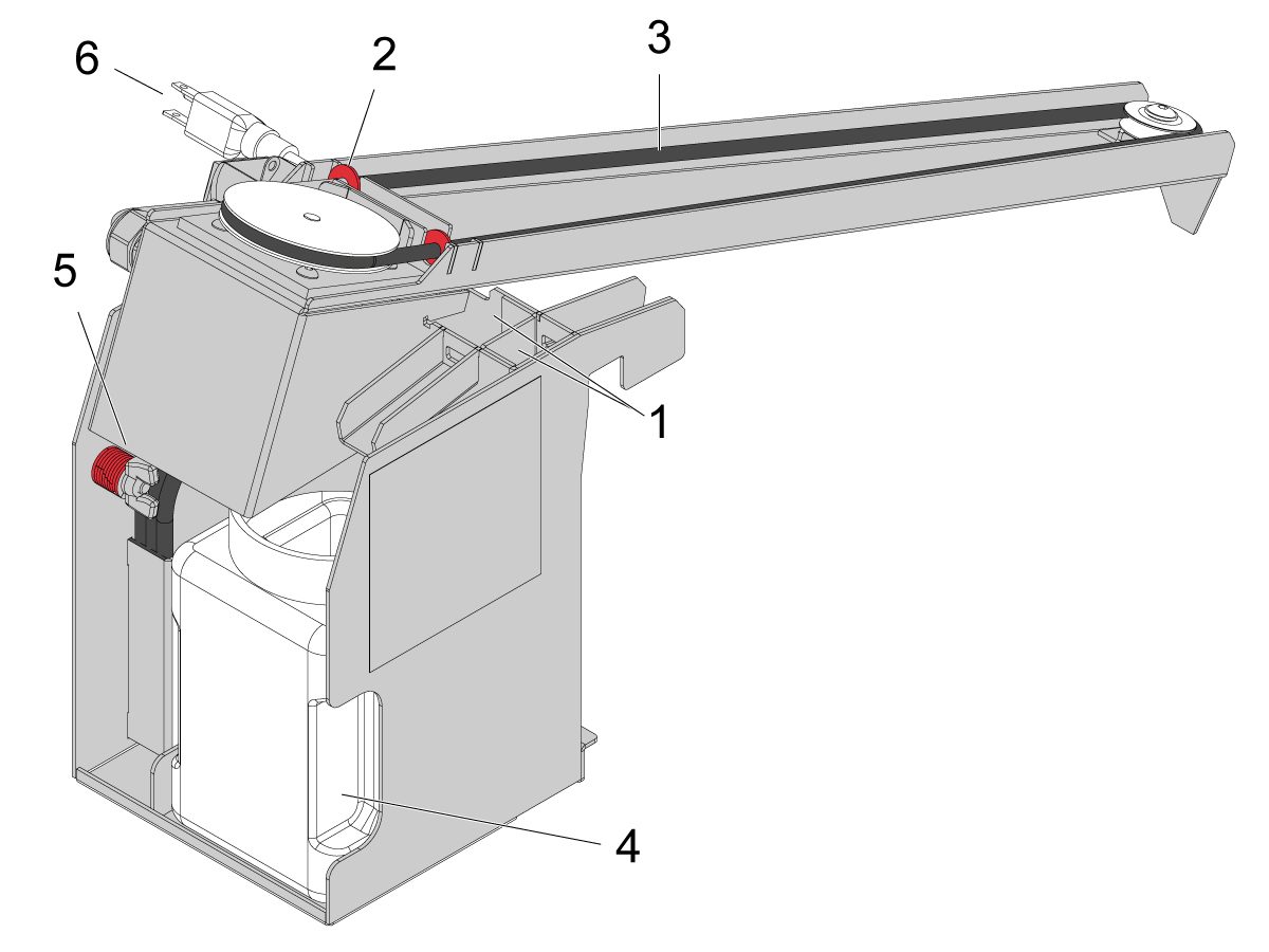
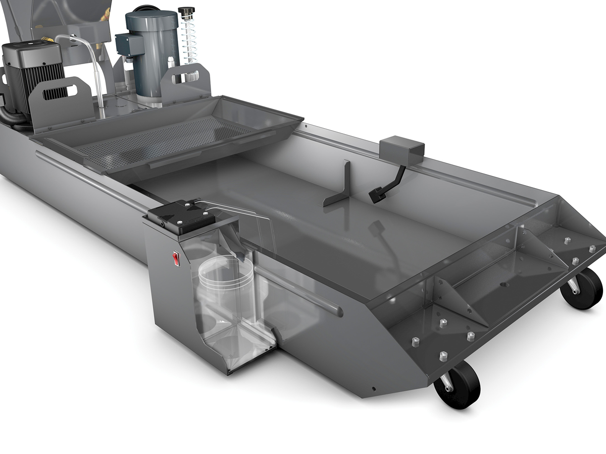
The image shows the following components of the Oil Skimmer system.

  1. Oil Skimmer Chamber (x2)
  2. Scraper (x2)
  3. O-ring
  4. Oil container
  5. Extra Scrapers and O-rings
  6. Power Cord with Switch

Symptom Table

Updated

The following table provides known symptoms and corrective actions for the Oil Skimmer system.

Symptom Possible Cause Corrective Action
Pulley and O-ring do not rotate despite motor turning. Pulley set screw backed out from motor drive Shaft Orient the motor drive shaft so that the flat side is facing the set screw bore in the pulley. Then tighten the set screw so that it is pressed against the flat side of the drive shaft. 
Oil does not dispense into bucket. The oil is too viscous. Clean the oil in the skimmer. If issue proceeds, clean the coolant tank. Refer to the Haas Oil Skimmer Maintenance procedure.
O-ring is damaged.  Check for chips wedged into the O-rings. Remove chips from the O-ring and the coolant tank. Replace O-ring. Refer to the Haas Oil Skimmer Maintenance procedure.
Both chambers are full of dirty oil.  Dump out the coolant oil mixture from the chamber. Clean thoroughly with water and refill with clean coolant. Refer to the Haas Oil Skimmer Maintenance procedure.
Oil drips onto the floor.  Inspect for holes or defects. Fill chamber with coolant and observe for a leak. 
Improper set-up on edge of tank. Make sure there are no chips or obstructions on the bottom of the oil skimmer and on the edge of the coolant tank. 
Both chambers are full of dirty oil.  Dump out the coolant oil mixture from the chamber. Clean thoroughly with water and refill with clean coolant. Refer to the Haas Oil Skimmer Maintenance procedure.
The motor is making excessive noise or behaving abnormally. The motor is damaged internally. Record a brief video clearly demonstrating the issue. Send the video with a brief description to your local HFO for further assistance. 
Chips are observed on the scraper. Chips or debris have collected and caught by the scraper.

Remove any debris or chips from the scraper.

Failure to remove chips or debris may result in premature motor failure.

The Oil Skimmer does not power on. The power outlet is not providing power to the unit.  Connect the unit to a good known power source.
The power cable has a broken or intermitten connection. A damaged power cable can sometimes cause intermittent connections. Movement like bending or wiggling may reveal a loose internal conductor. 

-Disconnect the power cable from the electrical outlet.
-Flip on the rocker swtich.
-Using a multimeter test the leads while wiggling the cable. 

Determine if the reading  on the meter change when wiggling the cable.  This can indicate a broken connection.
Coolant drips onto the floor on ST-10/15/L machines and/or the oil skimmer sags on the bracket causing spillage. Coolant snout is missing the ST-10/15 Oil Skimmer Extender to prevent coolant drips and/or it needs the stiffer Oil Skimmer Bracket. Order 93-1001137 OIL SKIMMER MOUNT BRACKET ST-10/15/L and refer to the Oil Skimmer Installation ST-10/15/L steps. 

Electrical Fault

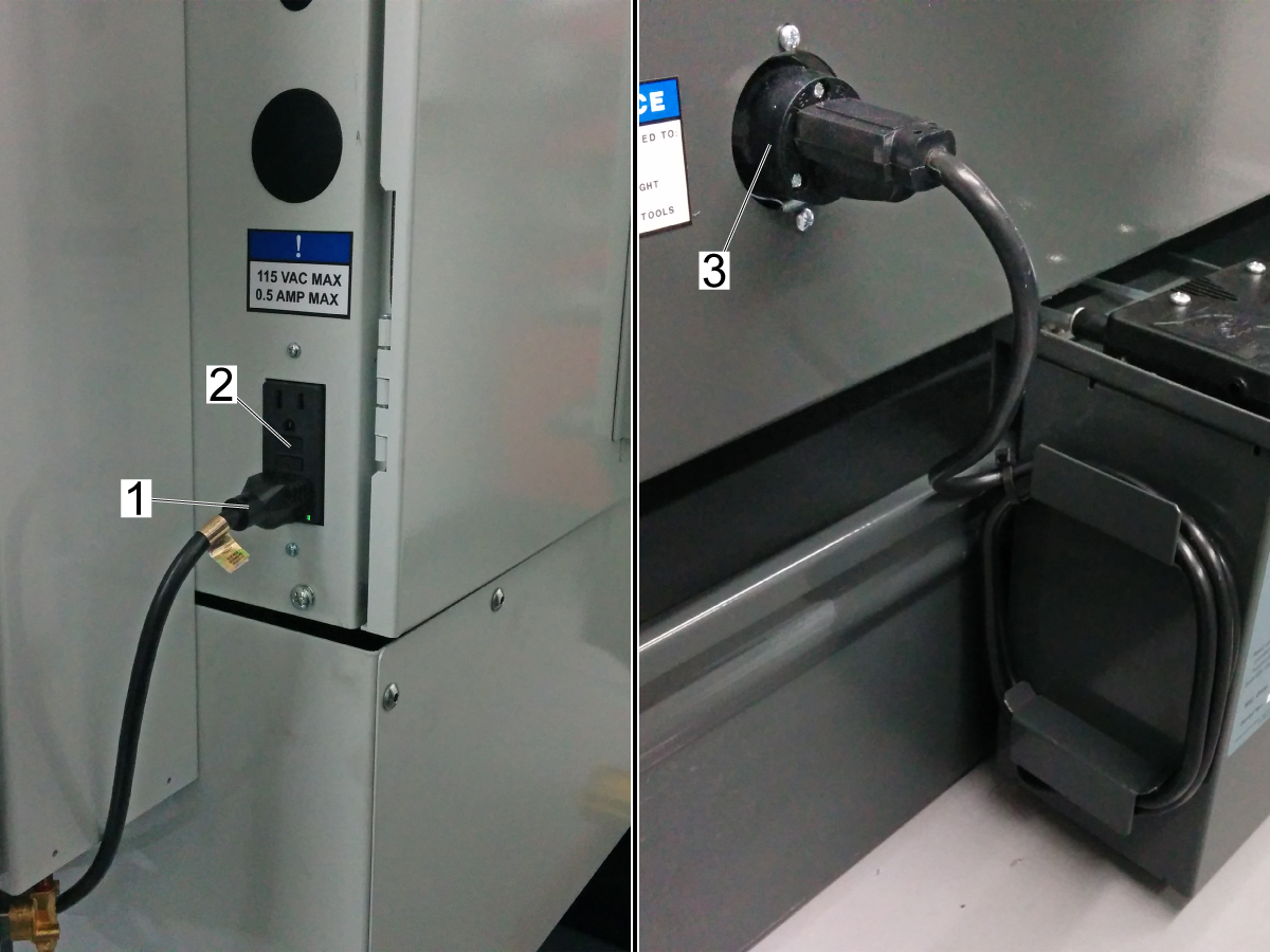
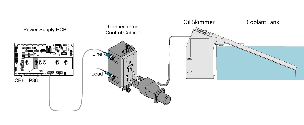
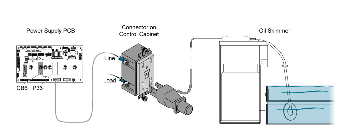
Make sure the connection is secure between the oil skimmer assembly cable [1] and the Ground-Fault Circuit-Interrupter [2] (GFCI). Some larger machines have an enclosure panel side-skirt connector [3] that the oil skimmer assembly cable [1] connects to.

Make sure the GFCI [2] has not been tripped. If it has, reset it.

Electrical Diagram

4.4 Zebra Oil Skimmer - Installation

Recently Updated

Zebra Oil Skimmer - Installation


AD0143

Applies to machines built from: January, 1989

Introduction

This procedure tells you how to install an Oil Skimmer system. The Oil Skimmer does these functions:

  • Automatically removes tramp oil. This decreases bacteria and helps to keep the coolant clean
  • Uses tubing that constantly turns in the coolant tank to remove the oil from the coolant. This puts the oil into an external container.
  • Starts and stops easily with the toggle switch on the side of the unit. You can also add an electrical timer to automatically start and stop the Oil Skimmer.

Machine Compatibility

You can install the Oil Skimmer on machines that have an external 55-gallon (208 L) or 95-gallon (360 L) coolant tank.

The machines in the list below have a hole and a slot in the coolant tank cover for the Oil Skimmer:

  1. All machines made after September 1, 2014.
  2. Mini Mills made after July 1, 2015.

For all other machines, you must use the Tank Cover Template to make the hole and the slot in the coolant tank cover.

For all machines made before October 2014, you must use the Enclosure Apron Template to makes holes in the enclosure apron for the female connector on the 25 FT EXTENSION CABLE [B].

 Note: This procedure shows a vertical machine. The installation on lathes and horizontal machines is similar.

Parts Required

KIT PN: "93-OIL-SKIMMER", COOLANT TANK OIL SKIMMER. QTY: 1

Tools Required

  • Drill
  • Jigsaw
  • Drill Bit - 5/32" (0.156")
  • Hole Saw - 1.75"

Templates

Tank Cover -Template

Use this template to make the hole and the slot in the coolant tank cover.

Cut the hole and slot on the left or right side of the cover. Choose the side for your machine that gives you access the Oil Skimmer.

On the top of the cover for the coolant tank, measure and mark the dimensions [A] from the front edge and [B] from the side edge of the cover.

  • A - 16.1" (40.9 cm).
  • B - 5.7" (14.5 cm).

Measure and mark these dimensions for the hole:

  • C - 3.5" (8.9 cm).
  • D - 1.5" (3.8 cm).
  • G - 0.5" (1.3 cm). Radius

Measure and mark these dimensions for the slot:

  • E - 1.8" (4.6 cm).
  • F - 0.2" (0.5 cm).

Cut and de-burr the hole and the slot.

Enclosure Apron - Template

For all machines made before October 2014, you must use this template to make (3) holes in the enclosure apron for the female connector on the 25 FT EXTENSION CABLE.

Choose a location in the apron that is near the Oil Skimmer. Put a mark in the apron [A] for the center of the hole.

Measure and mark these dimensions for the holes:

  • B - Ø1.75" (4.4 cm).
  • C - 0.07" (0.1 cm).
  • D - 1.00" (2.5 cm).
  • E - 0.90" (2.3 cm).
  • F - 0.25" (0.6 cm).
  • G - Ø0.156" (0.4 cm).
  • H - 0.156" (0.4 cm).

Cut and de-burr the (3) holes.

Oil Skimmer - Installation

1

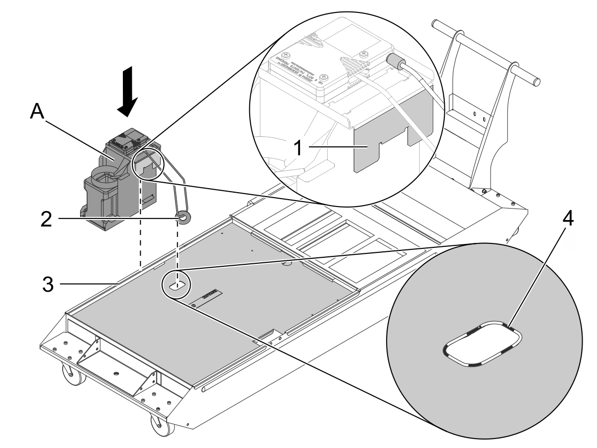
Install the OIL SKIMMER [A].

Put the long tab [1] on the OIL SKIMMER [A] into the slot [3] on the cover for the coolant tank.

Install the flexible grommet [4] on the hole.

Put the tubing and washer [2] into the hole on the coolant tank cover.

2

Attach the female connector on the 25 FT EXTENSION CABLE [B] to the enclosure apron. Use the (2) BOLTS [G].

Apply the DECAL [C] to the enclosure apron.

3

Connect the 25 FT EXTENSION CABLE [B] to the GFCI outlet [1] on the control cabinet.

Use the CABLE TIES [D], the CLAMPS [E], and the MOUNTS [F] as necessary to route the cable.

Connect the power cable [2] for the Oil Skimmer to the female connector on the 25 FT EXTENSION CABLE [B] in the enclosure apron.

4

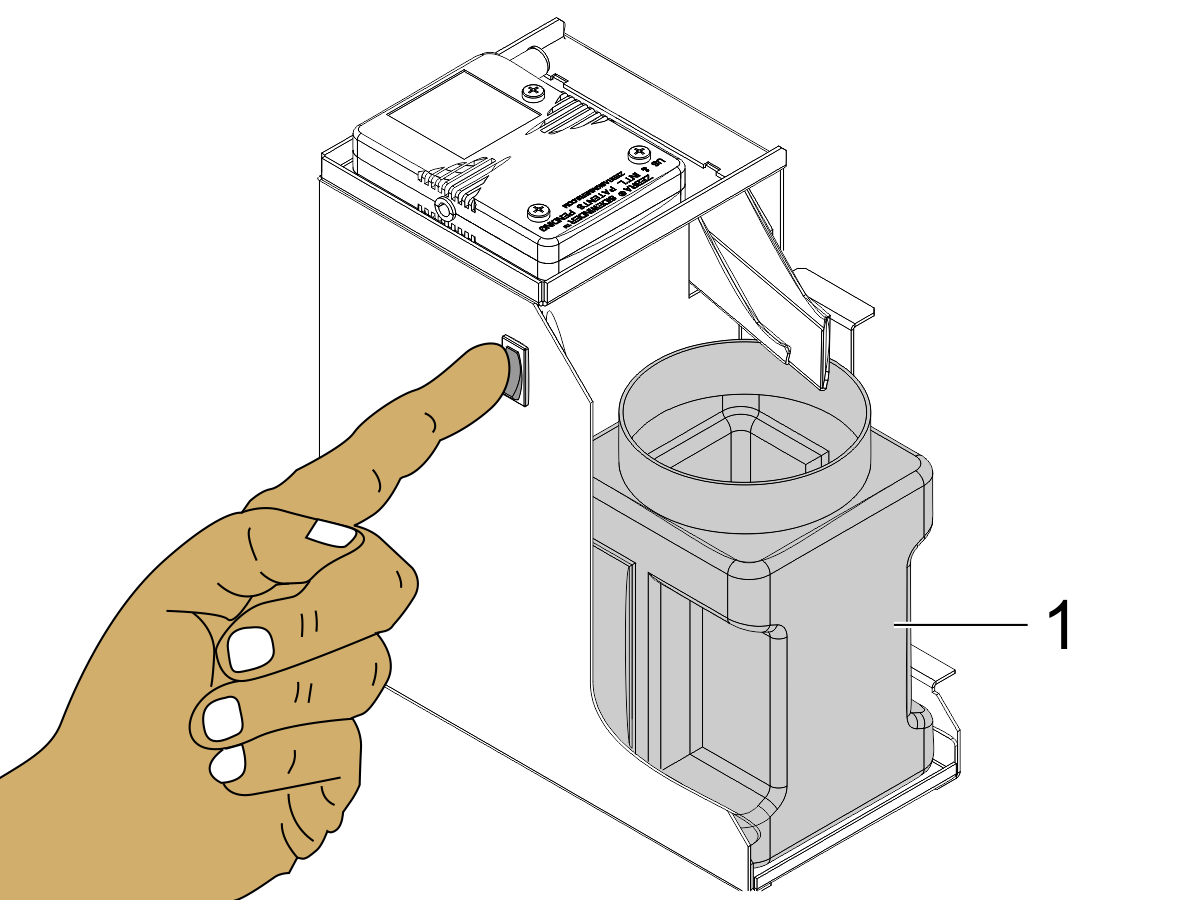
Push the toggle switch to start and stop the Oil Skimmer.

 Note: You can use an electrical timer to stop and start the Oil Skimmer automatically. This kit does not supply the electrical timer.

 Note: After you install the Oil Skimmer, check it frequently to determine how often you must empty the container [1].

4.5 Zebra Oil Skimmer - Maintenance

Recently Updated

Zebra Oil Skimmer - Tubing - Replacement


AD0234

Applies to machines built from: January, 1989

Parts Required

  • OIL SKIMMER TUBING SERVICE KIT (93-2352)

Tubing Replacement

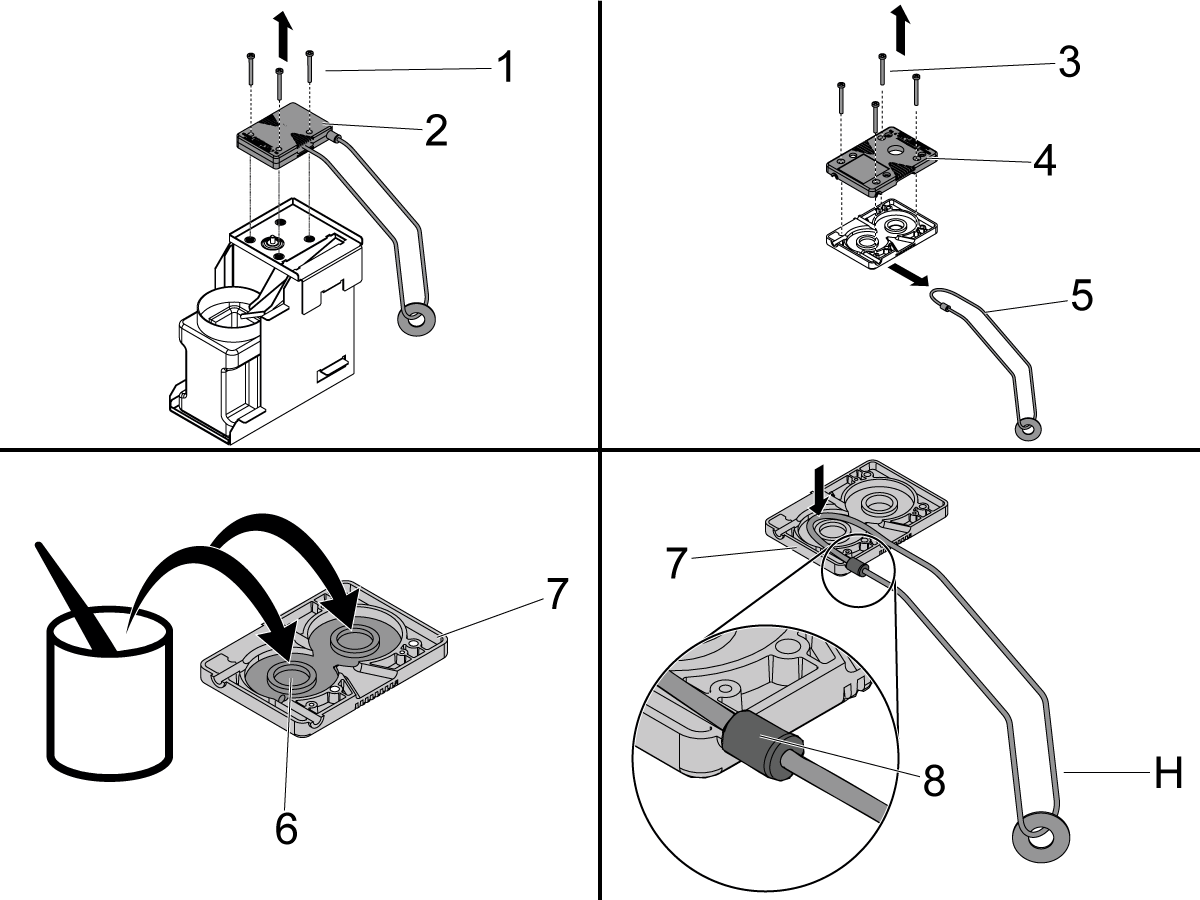
1

Unplug the Oil Skimmer power cable and remove the Oil Skimmer from the coolant tank.

Remove the (3) screws [1] and the cartridge [2] from the oil-skimmer assembly.

Turn the cartridge to the other side. Remove the (4) screws [3] and the bottom cover [4] of the cartridge.

Remove the tubing [5] and gears for the Oil Skimmer.

Add grease [6] to the top cover [7] of the cartridge.

Put the tubing on the top cover as shown with the replacement gears.

 Note: Make sure the ceramic scraper [8] is installed in the correct position on the top cover.

Install the bottom cover [4]. Use the (4) screws [3].

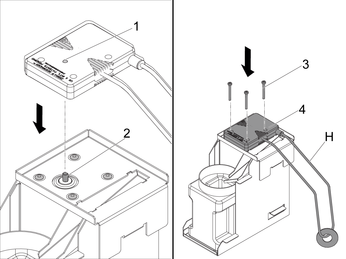
2

Align the motor shaft [2] to the drive-wheel hole [1]. The hole is on the bottom cover of the cartridge.

Attach the cartridge [4] to the Oil Skimmer. Use the (3) screws [3].

Install the Oil Skimmer.

Put the long tab on the Oil Skimmer into the slot on the cover for the coolant tank.

Connect the power cable for the Oil Skimmer.

Push the toggle switch to turn the Oil Skimmer on.

Make sure the tubing moves freely.

The Oil Skimmer operates correctly when the oil is scraped off of the tubing and drips into the container.

4.6 Zebra Oil Skimmer - Troubleshooting

Recently Updated

Zebra - Oil Skimmer - Troubleshooting Guide


TG0166

Introduction

The image shows the following components of the Oil Skimmer system.

  1. Oil Skimmer cartridge
  2. Pickup tube (Pickup kit for the oil skimmer.)
  3. Clamp (Push wire mount for cable routing.)
  4. 25 ft (7.6 m) Power Cord
  5. Oil container

Symptom Table

Symptom Possible Cause Corrective Action
The pickup tube does not circulate. The cable is unplugged or the GFCI breaker is tripped. Check wire connection and GFCI breaker
The pickup tube is broken or the ceramic wiper is damaged. Inspect and clean the drive wheels.
Check the pickup tube or the ceramic wiper for damage.
The gearbox is damaged. Inspect the oil skimmer cartridge.

Electrical Fault

Make sure the connection is secure between the oil skimmer assembly cable [1] and the Ground-Fault Circuit-Interrupter [2] (GFCI). Some larger machines have an enclosure panel side-skirt connector [3] that the oil skimmer assembly cable [1] connects to.

Make sure the GFCI [2] has not been tripped. If it has, reset it.

Mechanical Fault

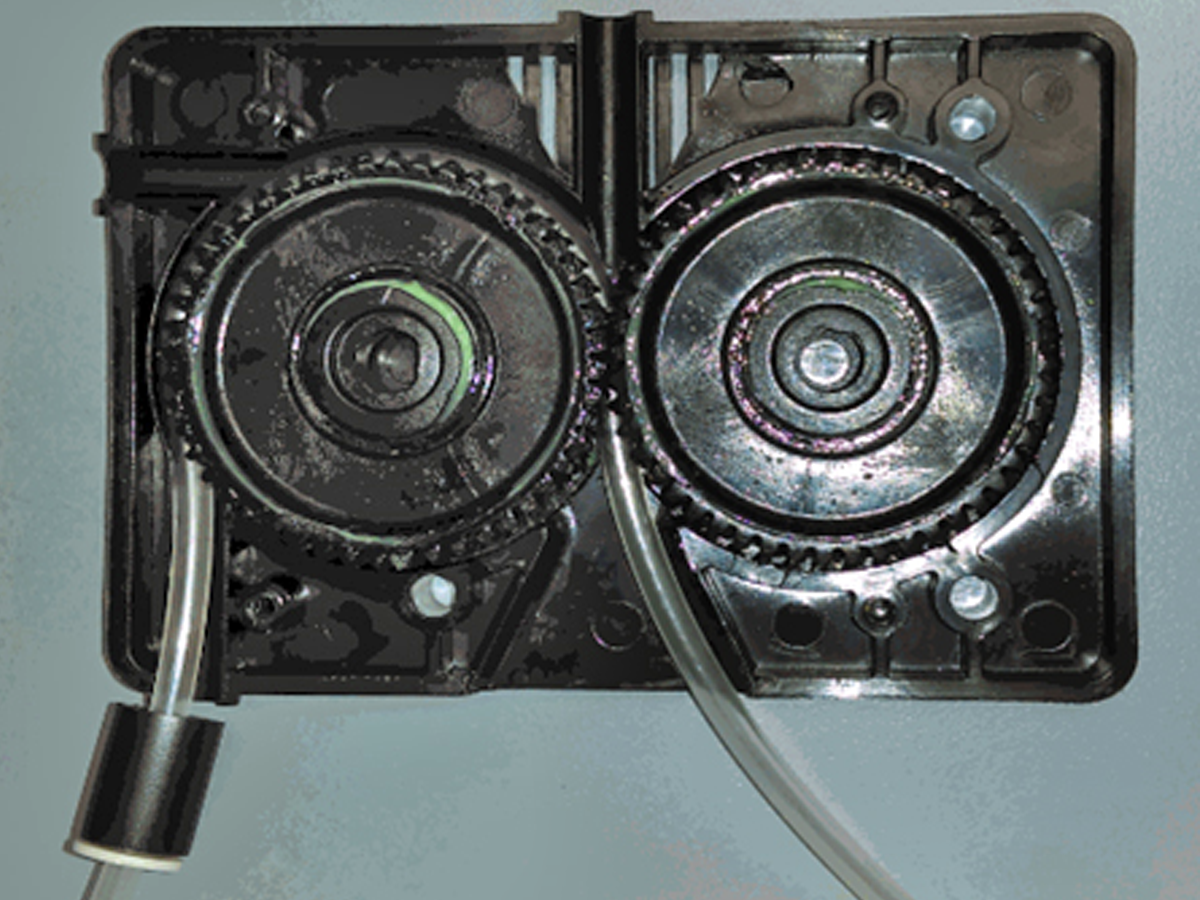
 Note: The illustration shows a disassembled oil skimmer cartridge.

Check that the drive wheels inside the oil skimmer cartridge are not damaged or jammed with chips. Remove the cover of the oil skimmer cartridge. Check the drive wheels for wear. If the teeth on the drive wheels are damaged or the center bore stripped, rebuild the oil skimmer cartridge with the service kit 93-2352.

Replace the pickup tube, ceramic wiper assembly, and gears together. Refer to Oil Skimmer - Tubing - Replacement for replacement instructions.

Electrical Diagram

Recently Viewed Items

You Have No Recently Viewed Items Yet

Feedback
Haas Logo

Haas Delivered Price

This price includes shipping cost, export and import duties, insurance, and any other expenses incurred during shipping to a location in France agreed with you as a buyer. No other mandatory costs can be added to the delivery of a Haas CNC Product.

KEEP UP WITH THE LATEST HAAS TIPS AND TECHNOLOGY...

Sign up now!   

HAAS TOOLING ACCEPTS THE FOLLOWING:

  • Service & Support
  • Owners
  • Request Service
  • Operator Manuals
  • Haas Parts
  • Rotary Repair Request
  • Pre-Install Guides
  • Shopping Tools
  • Build & Price a New Haas
  • Available Inventory
  • The Haas Price List
  • CNCA Financing
  • About Haas
  • Accessibility Statement
  • DNSH Statement
  • Export Compliance
  • Careers
  • Certifications & Safety
  • Contact Us
  • History
  • Terms & Conditions
  • Haas Tooling Terms & Conditions
  • Privacy
  • Warranty
  • Haas Community
  • Haas Certification Program
  • Haas Motorsports
  • Gene Haas Foundation
  • Haas Technical Education Community
  • Events
  • Join the Conversation
  • Facebook
  • X
  • Flickr
  • YouTube
  • LinkedIn
  • Instagram
  • TikTok
© 2026 Haas Automation, Inc – CNC Machine Tools

This site is protected by reCAPTCHA and the Google Privacy Policy and Terms of Service apply.

2800 Sturgis Rd., Oxnard, CA 93030
Toll Free: (888) 817-4446 / Fax: 805-278-8554