A Haas Factory Outlet (HFO) can answer your questions, and walk you through your best options.
CONTACT YOUR DISTRIBUTOR >A Haas Factory Outlet (HFO) can answer your questions, and walk you through your best options.
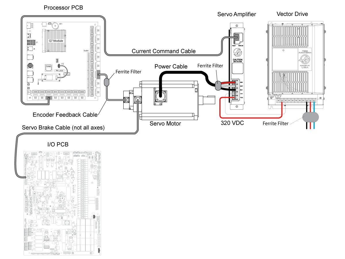
CONTACT YOUR DISTRIBUTOR >Haas machines are equipped with a close loop system to control axis motion. Below are the main components:
Procedure | Description |
Ballscrew - Vertical Axis - Replacement | This procedure explains how to replace the Z axis ballscrew on the vertical mill. |
Procedure | Description |
VMC - Z-Axis - Servo Motor - Replacement | This procedure tells you how to replace the servo motor on the vertical axis. This procedure applicable for VMC Z axis that is NOT equipped with the counterbalance system and has a solid coupling. |
Procedure | Description |
Ballbar Analysis - Quick Check Mode | This procedure tells you how to do a ballbar analysis. This procedure uses the Renishaw Ballbar software versions 4 and 5. This procedure uses the Quick Check Mode. |
Ballbar - QC20-W - Analysis | This procedure tells you how to do a Renishaw QC20-W ballbar analysis. The QC20-W BallBar uses a Bluetooth connection to send the measured data to the computer. |
Renishaw Ballbar Test - Plot Interpretation - Mills | This document has sample ballbar plots from machines with different geometric, dynamic and test hardware errors. |
Procedure | Description |
VMC - Ballscrew - Backlash Test - NGC | This procedure tells you how to do a test for axis backlash on the X, Y and Z axes of a vertical mill. |
Procedure | Description |
Axis Grid Offset Procedure - NGC | This procedure will show you how to set the grid offset on a axis servo motor. |
Download and fillout the Servo Motor Inspection Report Checklist below before replacing any parts.
Caution: When you do maintenance or repair on CNC machines and their components, you must always follow basic safety precautions. This decreases the risk of injury and mechanical damage.
Danger: Before beginning any work inside the control cabinet the High Voltage indicator light on the 320V Power Supply / Vector Drive must have been off for at least 5 minutes.
Some service procedures can be dangerous or life-threatening. DO NOT attempt a procedure that you do not fully understand. If you have any doubts about doing a procedure contact your Haas Factory Outlet (HFO) and schedule a service visit.
Symptom | Probable Cause | Corrective Action |
Alarm 1.9918, 2.9918 or 3.9918 X , Y or Z AXIS SERIAL ENCODER INTERNAL DATA ERROR Alarm 1.9922, 2.9922 or 3.9922 X, Y or Z AXIS MOTION CHANNEL FAULT DETECTED Alarm 1.9923, 2.9923 or 3.9923 X, Y or Z AXIS SOFTWARE DETECTED ENCODER FAULT Alarm 1.9930, 2.9930 or 3.9930 X, Y or Z AXIS SERIAL ENCODER POOR COMMUNICATION Alarm 1.9959, 2.9959 or 3.9959 X, Y or Z AXIS SERIAL ENCODER DISCONNECT Alarm 1.9948, 2.9948 or 3.9948 X, Y or Z AXIS SECONDARY ENCODER SERIAL FAULT Alarm 1.9949, 2.9949 or 3.9949 X, Y or Z AXIS SOFTWARE DETECTED SECONDARY ENCODER FAULT Alarm 1.9950, 2.9950 or 3.9950 X, Y or Z AXIS SOFTWARE DETECTED SECONDARY ENCODER FAULT Alarm 1.9951, 2.9951 or 3.9951 X, Y or Z AXIS SECONDARY ENCODER SERIAL COMMUNICATION FAULT Alarm 1.9960, 2.9960 or 3.9960 X, Y or Z AXIS SECONDARY SERIAL ENCODER CABLE FAULT |
The machine software is outdated. |
Alarm is obsolete New alarm for encoder faults updated in software. Update to latest version 100.21.000.1130 or Higher; Added Alarms 9719 and 9720 for Encoder Fault Detection on Mocon Primary and Secondary Axes. |
Alarm 1.9719, 2.9719 or 3.9719 X, Y or Z AXIS PRIMARY ENCODER SERIAL FAULT Alarm Subcode (0x1) Encoder Data Fault = (Alarm 9918 SERIAL ENCODER INTERNAL DATA ERROR) |
Encoder signals are affected by noise from high power cables. Faulty servo motor encoder. |
Refer to Serial Data Communication Faults / Electrical Noise section below. Check the servo motor for coolant intrusion. For VMC machines, new servo motor cables can be ordered to mitigate coolant intrusion. See HBC-N 03-13-25. |
Alarm 1.9719, 2.9719 or 3.9719 X, Y or Z AXIS PRIMARY ENCODER SERIAL FAULT Alarm Subcode (0x2) Encoder Internal Axis Fault 1 = (Alarm 9922 MOTION CHANNEL FAULT DETECTED) |
(The motion channel has reported an internal fault of a type that is not recognized by the control) |
Cycle power to the machine. If the issue persists, take an error report (Shift F3) and email to Haas Service |
Alarm 1.9719, 2.9719 or 3.9719 X, Y or Z AXIS PRIMARY ENCODER SERIAL FAULT Alarm Subcode (0x3) Encoder Internal Axis Fault 2 = (Alarm 9923 SOFTWARE DETECTED ENCODER FAULT) |
(Software has reported an internal fault of a type that is not recognized by the control.) |
Cycle power to the machine. If the issue persists, take an error report (Shift F3) and email to Haas Service |
Alarm 1.9719, 2.9719 or 3.9719 X, Y or Z AXIS PRIMARY ENCODER SERIAL FAULT Alarm Subcode (0x4) Encoder CRC Fault = (Alarm 9930 SERIAL ENCODER POOR COMMUNICATION) |
(Encoder signals are affected by noise from high power cables.) |
(Refer to Serial Data Communication Faults / Electrical Noise section below.) |
Alarm 1.9719, 2.9719 or 3.9719 X, Y or Z AXIS PRIMARY ENCODER SERIAL FAULT Alarm Subcode (0x5) Encoder Cable Fault = (Alarm 9959 SERIAL ENCODER DISCONNECT) |
(Cables are not connected correctly or encoder is faulty.) | (Inspect the cables and connectors. Refer to the Main Processor/Encoder Cable section below.) |
Alarm 1.9720, 2.9720 or 3.9720 X, Y or Z AXIS PRIMARY ENCODER SERIAL FAULT Alarm Subcode (0x1) Encoder Data Fault = (Alarm 9948 SECONDARY ENCODER INTERNAL DATA ERROR) |
Scale signals are affected by noise from high power cables. (Faulty Linear Scale, Configuration File issue; incorrect motor type or incorrect Scale type.) |
Refer to Serial Data Communication Faults / Electrical Noise section below. (Check Scale Encoder for coolant contamination.) |
Alarm 1.9720, 2.9720 or 3.9720 X, Y or Z AXIS PRIMARY ENCODER SERIAL FAULT Alarm Subcode (0x2) Encoder Internal Axis Fault 1 = (Alarm 9949 SOFTWARE DETECTED SECONDARY ENCODER FAULT) |
(The motion channel has reported an internal fault of a type that is not recognized by the control) | Cycle power to the machine. If the issue persists, take an error report (Shift F3) and email Haas Service |
Alarm 1.9720, 2.9720 or 3.9720 X, Y or Z AXIS PRIMARY ENCODER SERIAL FAULT Alarm Subcode (0x3) Encoder Internal Axis Fault 2 = (Alarm 9950 SOFTWARE DETECTED SECONDARY ENCODER FAULT) |
(Software has reported an internal fault of a type that is not recognized by the control.) |
Cycle power to the machine. If the issue persists, take an error report (Shift F3) and email to Haas Service |
Alarm 1.9720, 2.9720 or 3.9720 X, Y or Z AXIS PRIMARY ENCODER SERIAL FAULT Alarm Subcode (0x4) Encoder CRC Fault = (Alarm 9951 SECONDARY ENCODER SERIAL COMMUNICATION FAULT ) |
(Liner Scale signals are affected by noise from high power cables.) | (Refer to Serial Data Communication Faults / Electrical Noise section below.) |
Alarm 1.9719, 2.9719 or 3.9719 X, Y or Z AXIS PRIMARY ENCODER SERIAL FAULT Alarm Subcode (0x5) Encoder Cable Fault = (Alarm 9960 SECONDARY SERIAL ENCODER CABLE FAULT ) |
(Cables are not connected correctly or Linear scale is faulty.) | (Inspect the cables and connectors. Refer to the Main Processor/Encoder Cable section below.) |
Alarms 1.161, 2.161, 3.161 X, Y or Z AXIS DRIVE FAULT |
Faulty servo amplifier. | Check the corresponding amplifier assembly. Refer to Servo Amplifier - Troubleshooting Guide to troubleshoot the amplifier. |
Alarm 1.217, 2.217, 3.217 X, Y or Z AXIS PHASING ERROR | Cables are not connected correctly | Inspect the cables and connectors. Refer to the Main Processor/Encoder Cable section below. |
The wrong type of motor has been installed. | Check that the correct motor type has been installed. (Sigma-5 or Sigma-7) | |
Alarm 1.645, 2.645, 3.645 X, Y or Z AXIS AMPLIFIER GROUND FAULT | Faulty power cable. | Inspect the cables and connectors. Refer to Power Cable section below. |
Faulty servo motor. | Check the corresponding servo motor. Refer to Servo Motor section below. | |
Alarm 1.993, 2.993, 3.993 X, Y or Z AXIS SHORT CIRCUIT | Faulty power cable. | Inspect the cables and connectors. Refer to Power Cable section below. |
Faulty servo motor. | Check the corresponding servo motor. Refer to Servo Motor section below. | |
Alarm 1.103, 2.103, 3.103 X, Y or Z AXIS SERVO ERROR TOO LARGE Alarm 1.9920, 2.9920, 3.9920 X, Y or Z POSITION ERROR TOO LARGE |
Encoder signals are affected by noise from high power cables. Or Faulty encoder. | Refer to Serial Data Communication Faults / Electrical Noise section below. Check the encoder steps/revolution versus and ball screw pitch and verify the encoder counts are accurate per each rotation. |
The axis motor brake, is not disengaging when servos are enabled. | See the Motor Brake section below: | |
The axis ballscrew is damaged. | Check the corresponding axis ballscrew. Refer to Ballscrew - Troubleshooting Guide to troubleshoot the ballscrew. |
|
Faulty power cable. | Inspect the cables and connectors. Refer to Power Cable section below. | |
Misaligned ballscrew coupling due to a crash | Verify that the ballscrew motor coupling is aligned refer to the Ballscrew - Troubleshooting Guide for further information on how to re-align the coupler NOTE: Verify that the power cable is not faulty prior to attemping to align the motor coupling. |
|
Alarm 103 AXIS SERVO ERROR TOO LARGE, during the zero return process. The axis zero returns in the wrong direction. | The home sensor is being made during the zero return process causing the axis to zero return in the opposite direction. | Check the axis home switch to make sure there are no metal chips on top of the sensor. |
Alarm 552 TRIPPED CIRCUIT BREAKER (on UMC-1000) | Damaged wire conduit and wires within conduit. | Remove back panel. Inspect wire conduit. If damaged, contact Haas Service Department for assistance. |
The machine servos make a humming noise while sitting idle, jogging, or on a rapid. | The axis grid offset needs to be adjusted. | Perform the Axis Grid Offset adjustment procedure. |
The ballscrew is not aligned. | Verify that the ballscrew does not bind during travel and that it is correctly aligned. | |
Outdated parameters. | Download the latest configuration files. If the axis servo continues to hum, contact your local HFO for more troubleshooting information. | |
Alarm 9804 240 VAC GROUND FAULT gets generated when I zero return an Axis. |
There is a short circuit on the cable or motor. | Check for a short circuit on the corresponding servo motor and cable. Watch the Servo Power Cable and Motor Inspection Videos. Note: If alarm gets generated on a ST machine when the A-axis is zero returned the LT axis cable and motor must also be check for a short circuit condition. |
Alarm 9804 240 VAC GROUND FAULT AND/OR Alarm 993 SHORT CIRCUIT AND/OR Alarm 103 AXIS SERVO ERROR TOO LARGE |
There may be coolant intrusion on the axis servo motor. | Inspection the motor for coolant intrusion. For VMC machines, new servo motor cables can be ordered to mitigate coolant intrusion. See HBC-N 03-13-25. If motor is replaced because of coolant intrusion make sure to order the axis servo motor mount cover for motor mount that have a compatible motor mount cover. Refer to the VF/VR - X/Y Motor Mount Cover - Reference document to verify motor mounts and their covers. This document wil also have the part numbers for ordering. |
Sigma-5 servo motors, non-contact encoders output serial data signal to the control. If the serial data signal is missing or becomes unreliable the control will generate a serial data communication error. Electrical noise can cause the serial data signal from the encoder to become unreliable and cause false alarms. Follow the troubleshooting guide below to help eliminate the noise in the system.
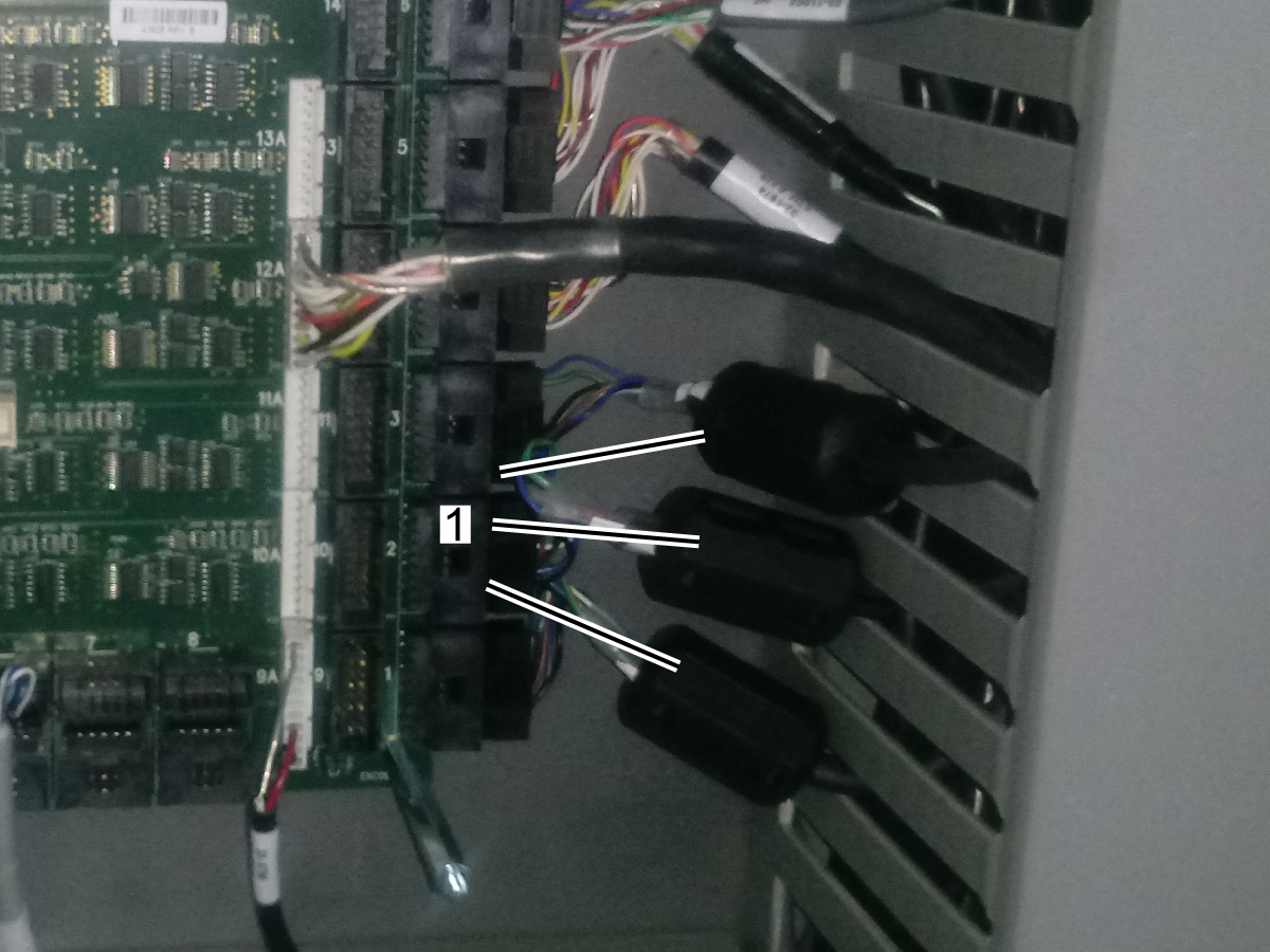
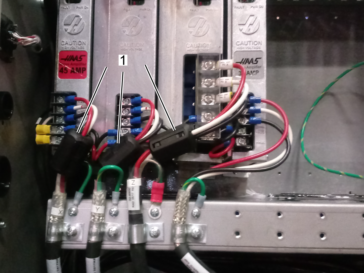
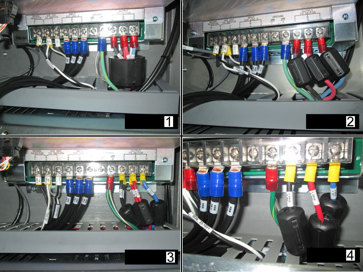
For a 40HP vector with 6 wire leads [1] use ferrite P/N 64-1254.
For a 40HP vector with 3 wire leads [2] use ferrite P/N 64-1252.
For a 20HP vector drive with 6 or 3 wire leads [3, 4] use ferrite P/N 64-1252.
Corrective Action:
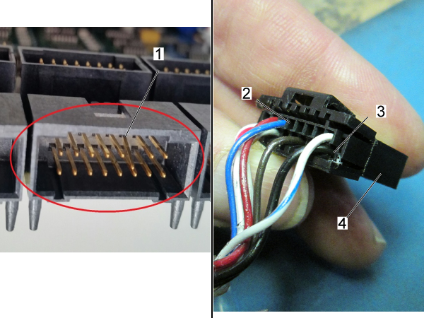
Examine the connector [1] on the Maincon. Make sure it is not damaged.
Examine the cable. Look for signs of damage or stiffness. The connector [4] has two housings [2,3] for the cable pins.
If the pins have been pushed into the motor, you must replace the motor and cable together.
Make sure the cable is firmly connected at both ends. Reseat both connections. Make sure the cable is installed in the correct connector at the Maincon or MOCON PCB.
Inspect the connector at the motor, look for loose connections between motor to cable or between cable spade terminals to amplifier. Check for connector contamination.
For VMC machines, new servo motor cables can be ordered to mitigate coolant intrusion. See HBC-N 03-13-25.
NOTE: Gently tug on the cables when checking for loose connection on the amplifier side. Pulling on the cables with excessive force can damage them.
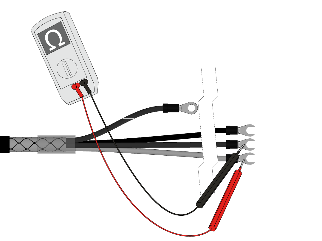
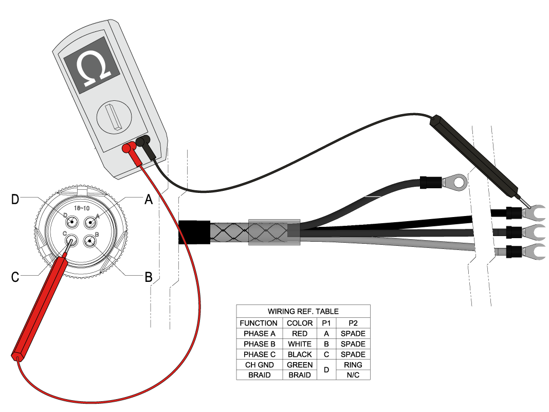
Look for signs of damage and stiffness on the cable and connector. Disconnect the power cable from the amplifier and motor. Measure the resistance from leg to leg (red, white, black wires), and from leg to ground (green/yellow wire). Make sure the measurements result in an open connection. Refer to the table below as a reference.
NOTE: If the machine is experiencing intermittent short circuit alarms move the axis to the location where the cable would be most bent before performing this test. This may improve the likeliness of finding an intermittent short.
Servo Power Cable Wiring Reference Table | |||
Function | Color | Motor End | Amplifiier End |
Phase A | Red | A | Spade |
Phase B | White | B | Spade |
Phase C | Black | C | Spade |
Chassis Ground | Green/Yellow | D | Ring |
Braid | Braid | Not Connected |
Perform a continuity test between the ground wire and the braided shield. If it fails the continuity test fails the cable shield is compromised.
NOTE: If the machine is experiencing intermittent short circuit alarms move the axis to the location where the cable would be most bent before performing this test. This may improve the likeliness of finding an intermittent short.
Check each leg from one end of the cable to the corresponding leg on the other end of the cable for continuity. Refer to the table above for wiring reference. If there is an open connection, there is a problem with the cable.
NOTE: If the machine is experiencing intermittent short circuit alarms move the axis to the location where the cable would be most bent before performing this test. This may improve the likeliness of finding an intermittent short.
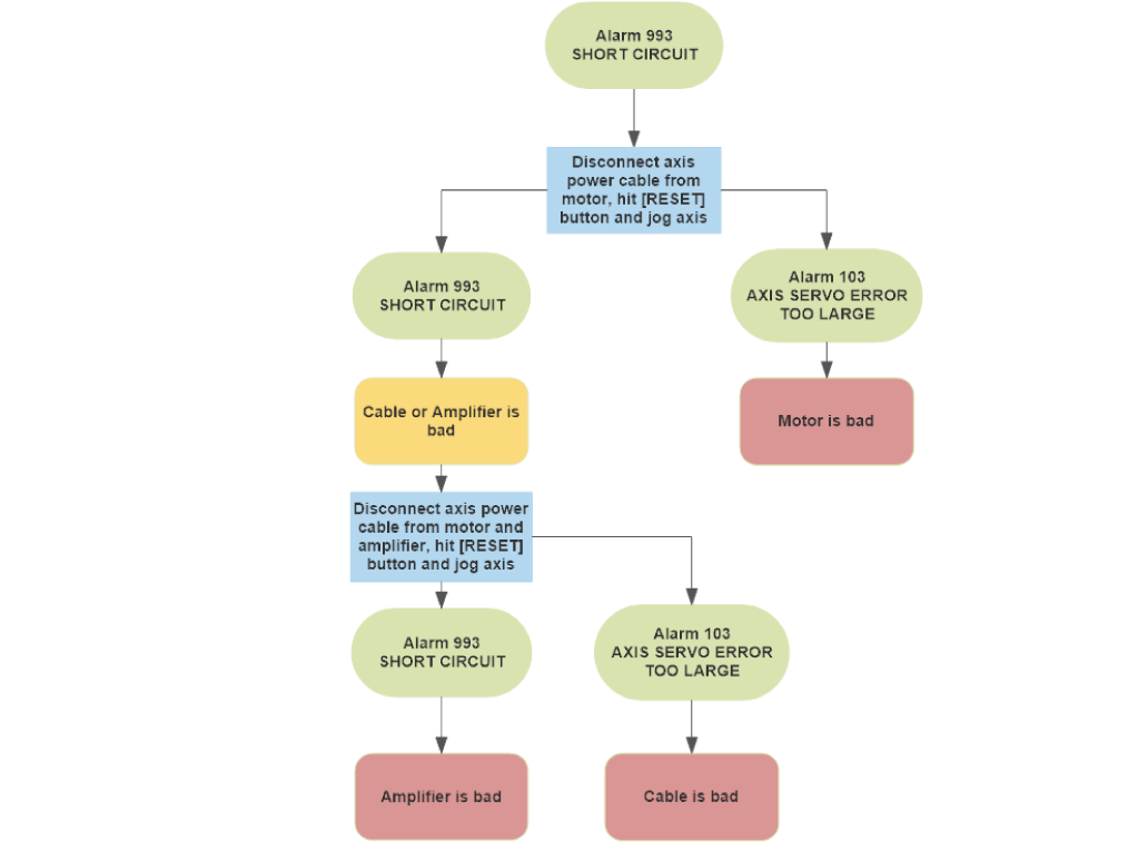
Use the following troubleshooting chart to determine whether the motor, amp, or cable is defective.
When Alarm 993 SHORT CIRCUIT occurs disconnect the axis power cable from the motor. Press [RESET] and jog the axis.
If Alarm 103 AXIS SERVO ERROR TOO LARGE occurs then the motor is defective. If another Alarm 993 SHORT CIRCUIT occurs then the cable or amp is defective.
To determine if the cable or amp is defective disconnect the axis power cable from the motor and amp. Press [RESET] and jog the axis.
If Alarm 993 SHORT CIRCUIT generates then the amplifier is defective. If Alarm 103 AXIS SERVO ERROR TOO LARGE generates the cable is defective.
Corrective Action:
Disconnect and inspect the power cable at the motor side. Verify the motor connectors are not contaminated, coolant contamination can generate drive fault alarms and damage the amplifier. Verify that the cable is connected to the corresponding amplifier as well.
For VMC machines, new servo motor cables can be ordered to mitigate coolant intrusion. See HBC-N 03-13-25.
Measure the resistance from the pins Labeled A, B, and C at the motor connector to the chassis ground.
Conduct a continuity test from the ground pin and chassis ground. The multimeter should beep or read less than 1 ohm resistance for continuity, otherwise then there is a short in the motor. Measure the resistance between the pins labeled A, B and C, refer to the table below for the resistance values.
NOTE: Nominal winding resistance has been added to the table for the 4-wire test method, when using a multimeter use the typical resistance value column for the expected values.
DC-1 30 Taper - Tool Carousel Motor without Brake
Important: Machines built before 3/1/2025 will have the motor without the brake.
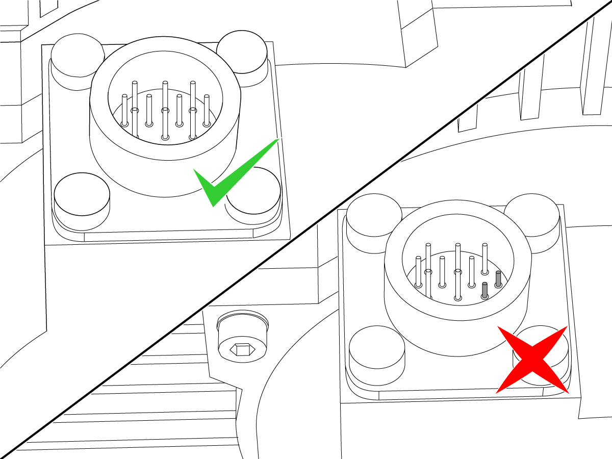
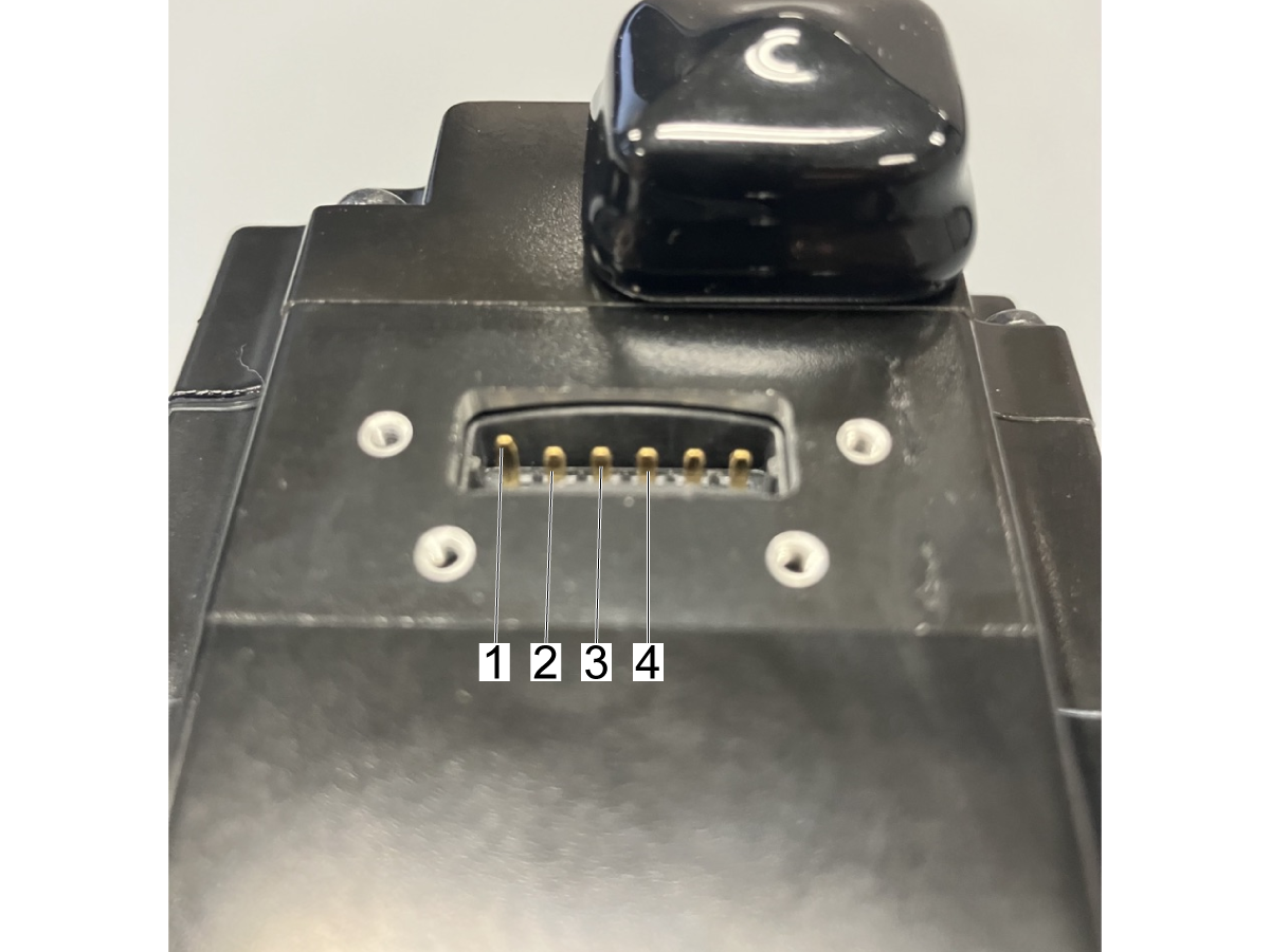
The DC-1 tool carousel motor is a sigma7 size 04 motor. The pinout for the phases looks different than other axis motors.
This image shows the pins on the motor connector:
NOTE: The Gnd pin [1] should be longer than the other pins as shown in the image.
NOTE: Nominal winding resistance has been added to the table for the 4-wire test method, when using a multimeter use the typical resistance value column for the expected values.
Motor type |
Haas PN |
MPN |
Motor size |
Nominal winding resistance (Ohms) |
Typical DMM measured winding resistance (Ohms) |
Sigma 5 |
62-10011/ 62-10010 |
SGMGV-09ADA-HA11/ SGMGV-09ADA-HA21 |
9 |
0.894 |
0.9 |
62-10013/ 62-10012 |
SGMGV-13ADA-HA11/ SGMGV-13ADA-HA21 |
13 |
0.554 |
0.6 |
|
62-10015/ 62-10014 |
SGMGV-20ADA-HA11/ SGMGV-20ADA-HA21 |
20 |
0.291 |
0.4 |
|
62-0101/ 62-10027 |
SGMSV-30ADV-YA11/ SGMSV-30ADA2E |
30 |
0.179 |
0.3 |
|
Sigma 7 |
62-0127B |
SGM7A-02AFK-HA21 |
2 |
6.5 |
6.6 |
62-4445 | SGM7A-04A7D61 | 4 | 4.3 | 4.2 | |
62-0117/ 62-0124 |
SGM7G-09AFA-HA11/ SGM7G-09AFA-HA21 | 9 | 0.882 | 1.0 | |
62-0119/ 62-0118 |
SGM7G-13AFA-HA11/ SGM7G-13AFA-HA21 |
13 |
0.557 |
0.6 |
|
62-0120/ 62-0123 |
SGM7G-20AFA-HA11/ SGM7G-20AFA-HA21 |
20 |
0.286 |
0.4 |
|
62-0122/ 62-0121 |
SGM7G-30AFB-HA11/ SGM7G-30AFB-HA21 |
30 |
0.177 |
0.2 |
|
Mitsubishi J5 |
62-0138/ 62-0141 |
HK-ST102WK-S101212/ HK-ST102WBK-S101212 |
9 |
1.254 |
1.4 |
62-0137/ 62-0140 |
HK-ST172WK-S101212/ HK-ST172WBK-S101212 |
13 |
0.807 |
0.9 |
|
62-0142/ 62-0139 |
HK-ST202AWK-S101212/ HK-ST202AWBK-S101212 |
20 |
0.558 |
0.7 |
|
Mitsubishi J3 |
62-0087/ 62-0088 |
HF-SP81MK-S12/ HF-SP81MBK-S12 |
9 |
1.149 |
1.4 |
62-0089/ 62-0095 |
HF-SP131MK-S12/ HF-SP131MBK-S12 |
13 |
0.692 |
0.8 |
|
62-0096/ 62-0097 |
HF-SP181MK-S12/ HF-SP181MBK-S12 |
20 |
0.456 |
0.5 |
|
Delta |
62-0108/ 62-0109 |
ECMC-FW1308RS/ ECMC-FW1308SS |
9 |
0.737 |
0.8 |
Corrective Action:
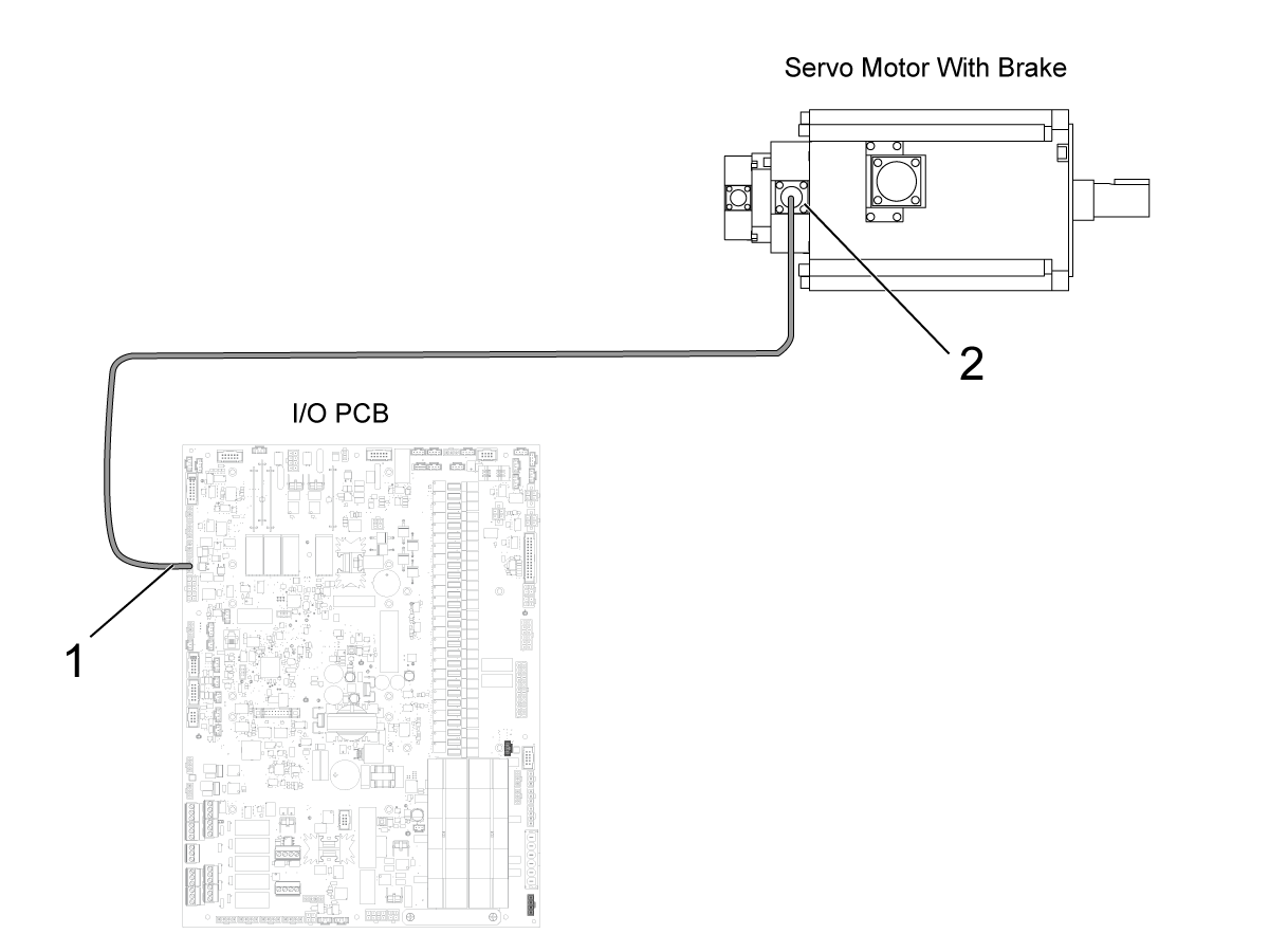
Reseat the the connection for connectors P3, P4, or P5 on the I/O PCB.
Measure the voltage across the red and black cables.
Press [EMERGENCY STOP]. There should be no voltage.
Press [RESET] to clear the alarms. The voltage should be between 20-30 VDC.
Examine the connection at the motor's brake [2] and power connectors [3] for contamination. Reseat the connections.
If no voltage is present, refer to:
Download and fill out the Ballscrew Inspection Report Checklist below before replacing any parts.
Symptom | Possible Cause | Corrective Action |
Alarm 103 SERVO ERROR TOO LARGE Alarm 104 SERVO ERROR TOO LARGE Alarm 105 SERVO ERROR TOO LARGE The axis motion is very rough when the axis is jogged. There is unusual noise when the axis moves. |
There is insufficient lubrication. | Check the ballscrew for correct lubrication. |
The ballscrew or ballnut is damaged. | Check the ballscrew and ballnut for damage. | |
The ballscrew support bearings are damaged. | Check the ballscrew support bearings for damage. | |
Ballscrew misalignment | Ballscrew misalignment | |
Faulty power cable | Check the Servo Motor - Troubleshooting Guide for further instructions on how to troubleshoot a faulty cable | |
Misaligned ballscrew coupler | If the machine has been crashed the coupler may have moved out of alignment. Refer to the Coupler section of this procedure for more information on how to align a coupler. NOTE: It is important to troubleshoot for a faulty cable before realigning the |
|
Alarm 108 AXIS SERVO OVERLOAD | Ballscrew misalignment | Ballscrew misalignment |
The cutting tool is not sharp or is damaged. | Install a new device or a new tool insert. | |
The axis position does not repeat within specification. Inconsistent accuracy, positioning, backlash. |
There is insufficient lubrication, or the lubrication is contaminated. | Check the ballscrew for correct lubrication. |
The ballscrew or ballnut is damaged. | Check the ballscrew and ballnut for damage. | |
The ballscrew coupling is damaged. | Check the ballscrew coupling for damage. | |
There is excessive thermal growth. | Correct your application | |
Dual ballscrew GM-2 is experiencing different and high loads during a movement on the X-axis and slave (F1)-axis. | Machine may have moved during shipping | Before taking any corrective action please verify the machine is experiencing the following behavior:
Note: F1 axis may need to be made visible
If your machine is experiencing these issues please provide an inspection report and error report to Haas Service for analysis. Please also complete the Dual Ballscrew Inspection Checklist located at the begining of this document. Further instructions will be provided after analysis. |
Machine was built with grade 7 ballscrews and lead compensations are not set correctly |
IMPORTANT: Machines are currently equipped with either a hydraulic counterbalance system or an electric brake motor. Care must be taken, in either case, to avoid damaging the machine or severely injuring yourself. Heed all warnings and cautions, and read all the steps of the procedure before starting any alignment.
If the machine is equipped with a hydraulic counterbalance, a shaft stop block must be used to secure the spindle head. Do not move the spindle during ballscrew service.
If the servo load is not consistent, the following procedure should be used to align the Ball Screw:
Corrective Action:
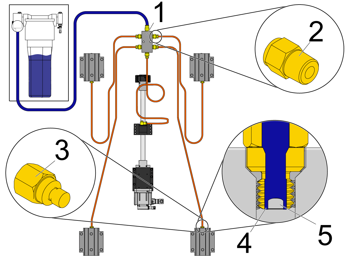
Make sure there is a light coat of oil or grease on the surface of the ballscrew. If there is not, inspect the entire lubrication system for leaks and clogs, including all tubes, hoses, and fittings. Check for leaks on each axis: A leak at one axis will cause a lack of lubrication at a different axis. Check for oil or grease puddles to help locate the source of the leak.
Note: The Haas Liquid Grease lubrication system uses adapter fittings [2] in the axis manifolds [1]. The linear guide trucks and ballnuts use restrictor fittings [3]. The restrictor fitting has a gap [5] between the threads and the set screw [4]. This forces the manifold-fed grease to pass through the gap [4] to lubricate the axes.
Make sure the correct lubrication is used. Refer to Lubricant, Grease, and Sealant Tables for Haas Machine Components.
Corrective Action:
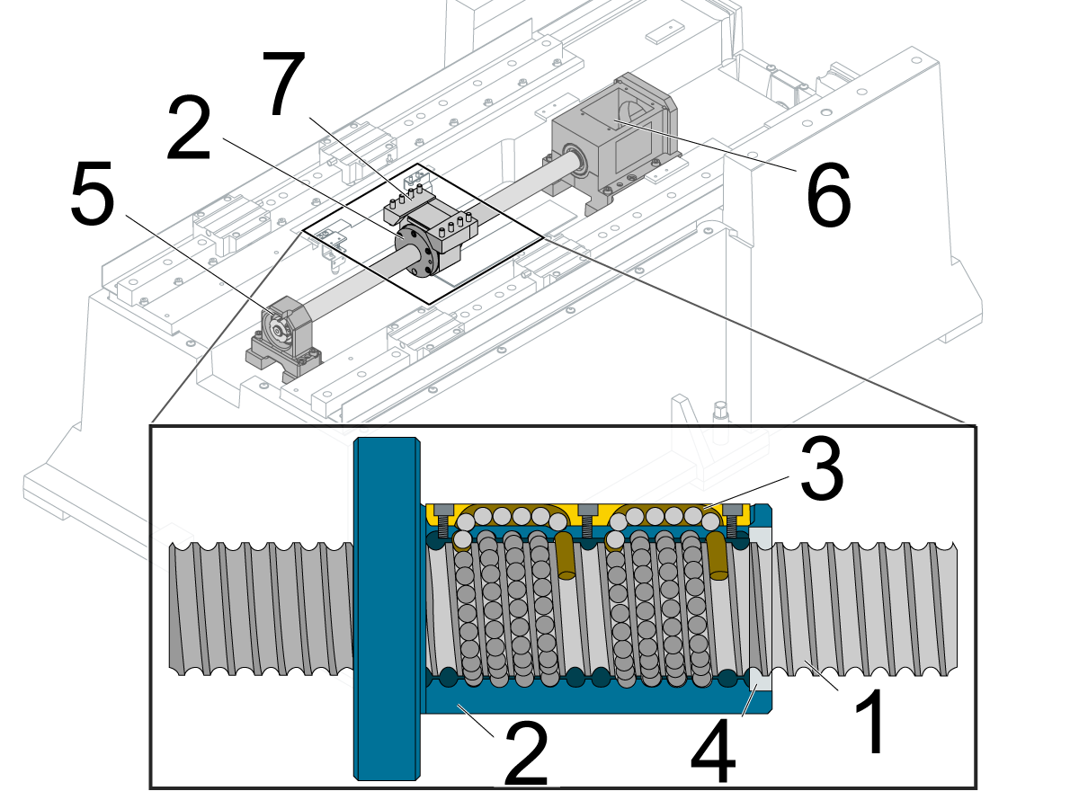
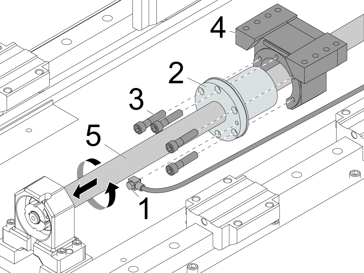
Disconnect the lubrication fitting [1] from the ballnut [2]. Remove the screws [3] that attach the ballnut [2] to the ballnut housing [4].
Ballscrew/Ballnut
Separate the ballnut [2] from the ballnut housing [4]. Rotate the ballnut [2] by hand and hold the ballscrew [5] so it does not rotate, and the ballnut [2] will move away from the ballnut housing [4].
The ballnut [2] should rotate smoothly. If there is resistance or if it binds, the ballscrew [5] and ballnut [2] are faulty.
Support Bearing
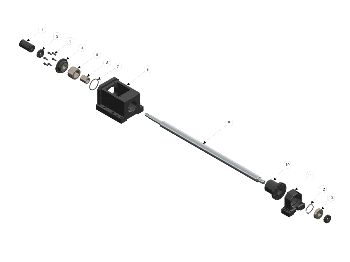
Rotate the ballscrew [5] by hand. If there is resistance or if it binds, the bearings are faulty. Remove the ballscrew [5] and check the support bearings and bearing pack to determine which components need to be replaced.
IMPORTANT: Machines are currently equipped with either a hydraulic counterbalance system or an electric brake motor. Care must be taken, in either case, to avoid damaging the machine or severely injuring yourself. Heed all warnings and cautions, and read all the steps of the procedure before starting any alignment.
If the machine is equipped with a hydraulic counterbalance, a shaft stop block must be used to secure the spindle head. Do not move the spindle during ballscrew service.
Corrective Action:
Refer to the Ballscrew Backlash Test procedure that is appropriate for your machine.
Power off and lock out the machine. Remove the necessary covers to access the axis with the problem. Remove the axis motor cover.
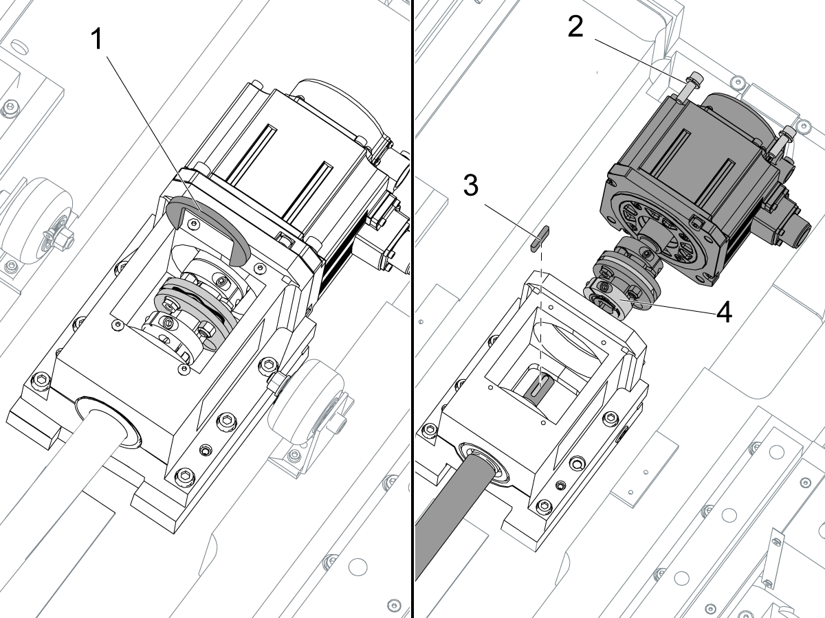
Install the coupler-installation tool [1] on the motor coupling. Turn the ballscrew so you can see the screw [4] for the motor-coupling clamp.
Remove the motor screws [2]. Loosen the screw [4] on the motor-coupling clamp. Remove the motor with the motor-coupling assembly. Remove the ballscrew key [3]. Inspect for damage or wear on the key or keyway.
Note: If the axis motor is disconnected from the ballscrew, the grid offset and the work offset (such as G54) must be reset. Go to Axis Servo Motor - Set Grid Offset Parameter.
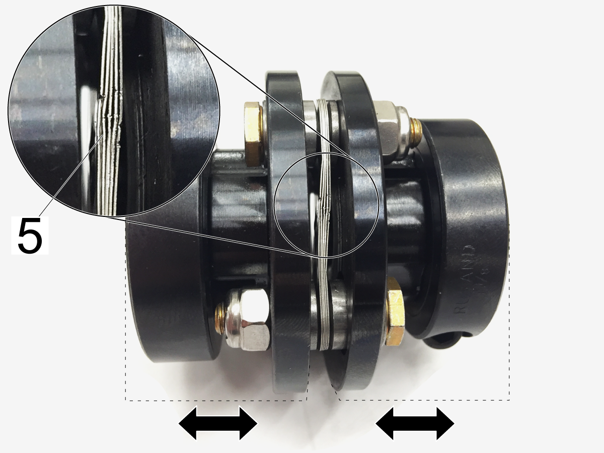
Make sure the flex pack [5] in the coupler is not damaged. It should be straight, and tightly compressed together.
Note: If the axis motor is disconnected from the ballscrew, the grid offset and the work offset (such as G54) must be reset. Go to Axis Servo Motor - Set Grid Offset Parameter.
COUPLER ALIGNMENT:
To realign the coupler to the motor shaft install the mounting bolts loosely and float the motor in until the coupling slides from between both the motor shaft and ballscrew shaft easily.
Torque the bolts down and verify the coupler still slides easily between the two shafts.
Torque the coupler pinch bolt to the specifications found on __________.
Corrective Action:
You must warm up the machine axes to bring the ballscrews to a normal temperature for operation. You can warm up the machine automatically by changing certain settings: Use either Settings 158-160 or Settings 109-112. Do not use both.
IMPORTANT: If your application involves moving a single axis repeatedly back and forth over a small area of the ballscrew, the ballnut will heat up the ballscrew and cause thermal expansion. It will also not lubricate correctly because of the short stroke. Every few minutes, it is necessary to move 80% to 90% of the axis travel in order to cycle the grease throughout the ballnut. This is common on smaller machines with a smaller work envelope.
For lathes: Go to the DIAGNOSTICS screen. Check the X Axis Temp. If the measurement fluctuates or has no value, you must inspect the thermal sensor on the ballnut.
This section applies to Machines with Dual Ballscrews.
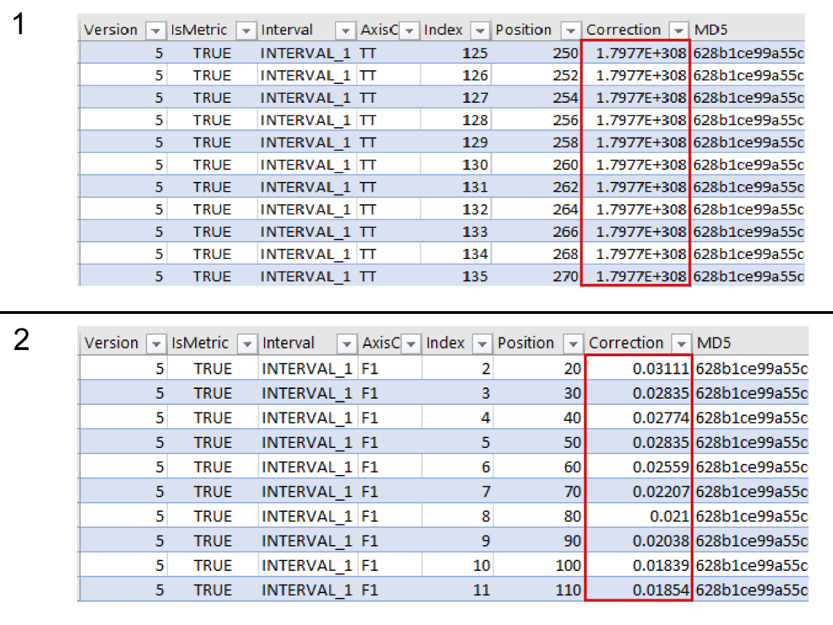
Open the LSC.LSCX file found in the Error report in a spreadsheet program. Determine if axis compensation has been applied by looking at the correction column.
Note: Compensation values will vary between machines.
Recently Viewed Items
You Have No Recently Viewed Items Yet
美元价格不包括关税、报关费用、保险费、增值税及运费。
USD prices DO NOT include customs duty, customs fees, insurance, VAT, or freight.
人民币价格包含关税、报关费用、货运保险和增值税, 但不包括运费。
CNY prices include customs duty, customs fees, insurance, and VAT. DOES NOT include freight.
This price includes shipping cost, export and import duties, insurance, and any other expenses incurred during shipping to a location in France agreed with you as a buyer. No other mandatory costs can be added to the delivery of a Haas CNC Product.
KEEP UP WITH THE LATEST HAAS TIPS AND TECHNOLOGY...
HAAS TOOLING ACCEPTS THE FOLLOWING:
This site is protected by reCAPTCHA and the Google Privacy Policy and Terms of Service apply.
2800 Sturgis Rd., Oxnard, CA 93030
Toll Free: (888) 817-4446 / Fax: 805-278-8554