-
machines
-
Vertical Mills
Vertical Mills
-
Multi-Axis Solutions
Multi-Axis Solutions
-
Lathes
Lathes
-
Horizontal Mills
Horizontal Mills
-
Rotaries & Indexers
Rotaries & Indexers
-
Special Series
Special Series
-
Automation Systems
Automation Systems
-
Desktop Machines
Desktop Machines
-
Shop Equipment
Shop Equipment
-
Fabrication Machines
Fabrication Machines
SHOPPING TOOLSWANT TO TALK TO SOMEONE?A Haas Factory Outlet (HFO) can answer your questions, and walk you through your best options.
CONTACT YOUR DISTRIBUTOR > -
Vertical Mills
-
Options
-
/2026-04-VOP-SquareComponent.jpg/_jcr_content/renditions/cq5dam.thumbnail.319.319.png) Value Option Packages
Value Option Packages
Value Option Packages
Value Option Packages -
 Spindles
Spindles
Spindles -
 Tool Changers
Tool Changers
Tool Changers -
 4th- | 5th-Axis
4th- | 5th-Axis
4th- | 5th-Axis -
 Turrets & Live Tooling
Turrets & Live Tooling
Turrets & Live Tooling -
 Probing
Probing
Probing -
 Chip & Coolant Management
Chip & Coolant Management
Chip & Coolant Management -
 The Haas Control
The Haas Control
The Haas Control -
 Product Options
Product Options
Product Options -
 Tooling & Fixturing
Tooling & Fixturing
Tooling & Fixturing -
 Workholding
Workholding
Workholding -
 5-Axis Solutions
5-Axis Solutions
5-Axis Solutions
SHOPPING TOOLSWANT TO TALK TO SOMEONE?A Haas Factory Outlet (HFO) can answer your questions, and walk you through your best options.
CONTACT YOUR DISTRIBUTOR > -
-
Why Haas
Discover the Haas Difference
-
Service
Welcome to Haas Service
- Videos
-
SHOPPING TOOLSWANT TO TALK TO SOMEONE?
A Haas Factory Outlet (HFO) can answer your questions, and walk you through your best options.
CONTACT YOUR DISTRIBUTOR > -
- Haas Tooling
- Haas Service Parts


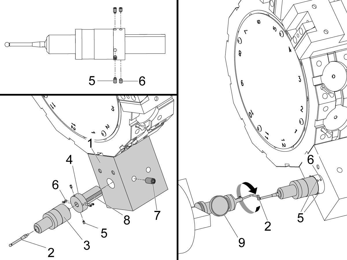
---installation/Renishaw-MPF40-2-Set-up-Probe.png)
---installation/Renishaw-Probe-Mill-Install-Toolholder_4.png)
---installation/Renishaw-OMP40-1-Align-Probe.png)
---installation/work-probe-adjust.png)
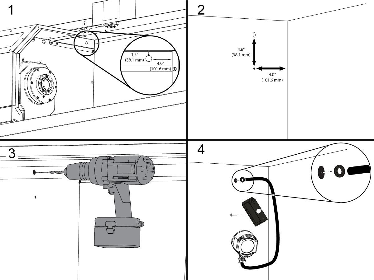
---installation/InstallWIPS.png)
---installation/SafetyStrap.png)
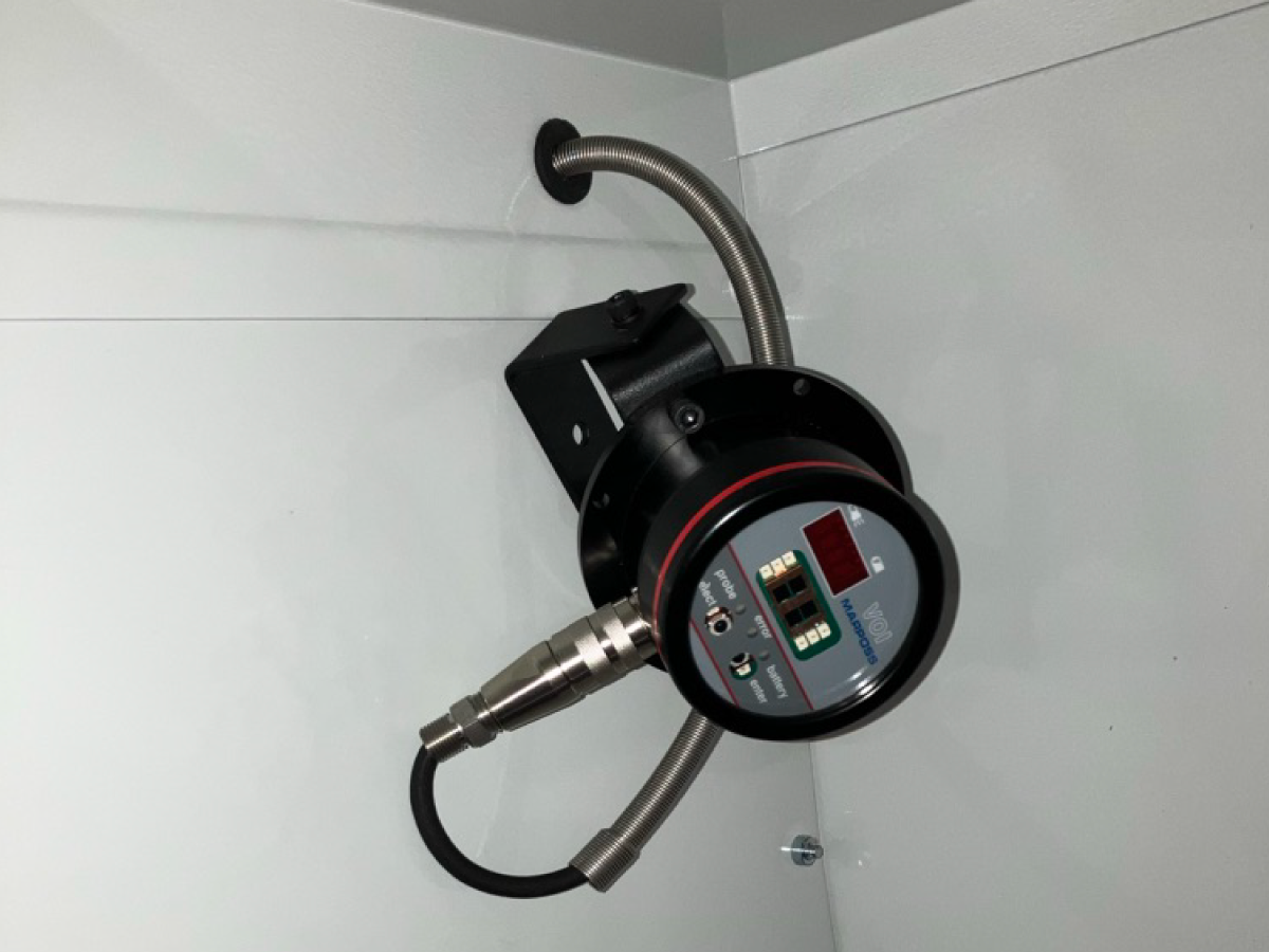
---installation/Reinshaw-Install.jpg)
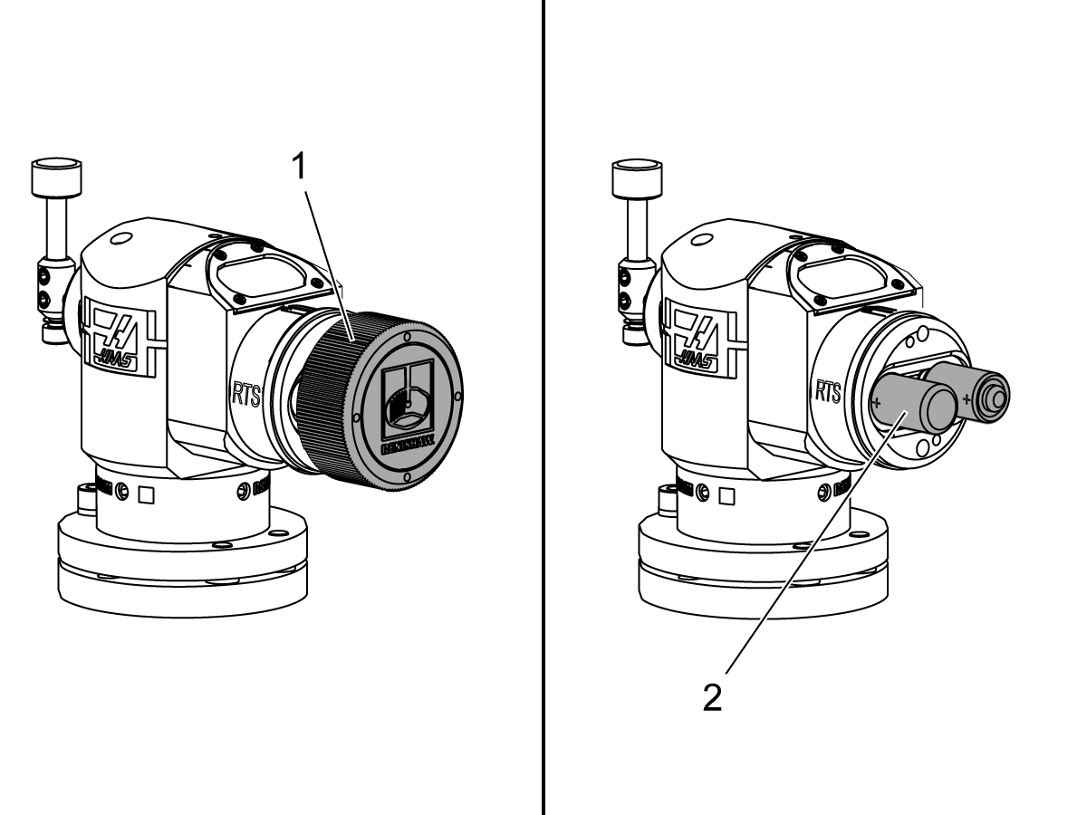
---installation/Renishaw-OTS-Battery-Installation.png)
---installation/WIPSPositioning_UMC.png)
---installation/WIPSPositioning_Flipped.png)
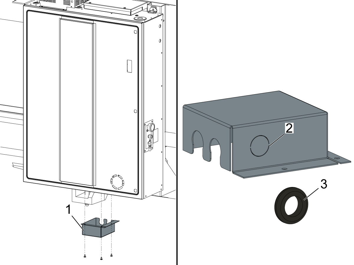
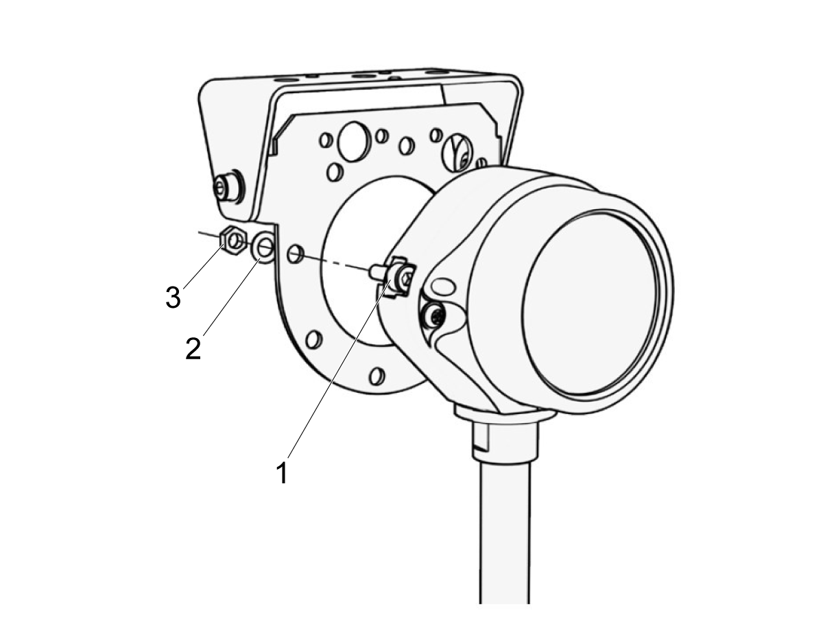
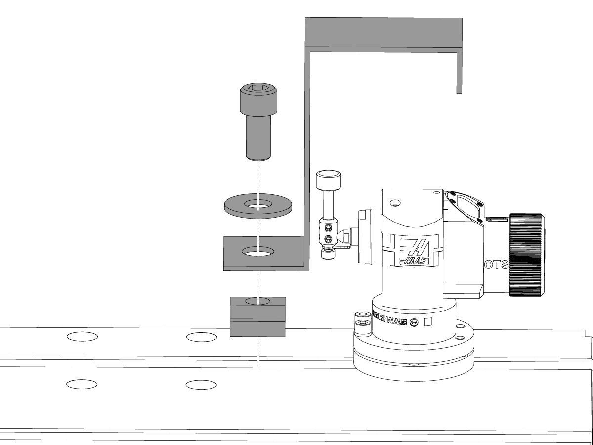
---installation/Renishaw-OTS-Mount-the-Base.png)
---installation/Renishaw-OTS-Calibrate-Sensor-FA.png)
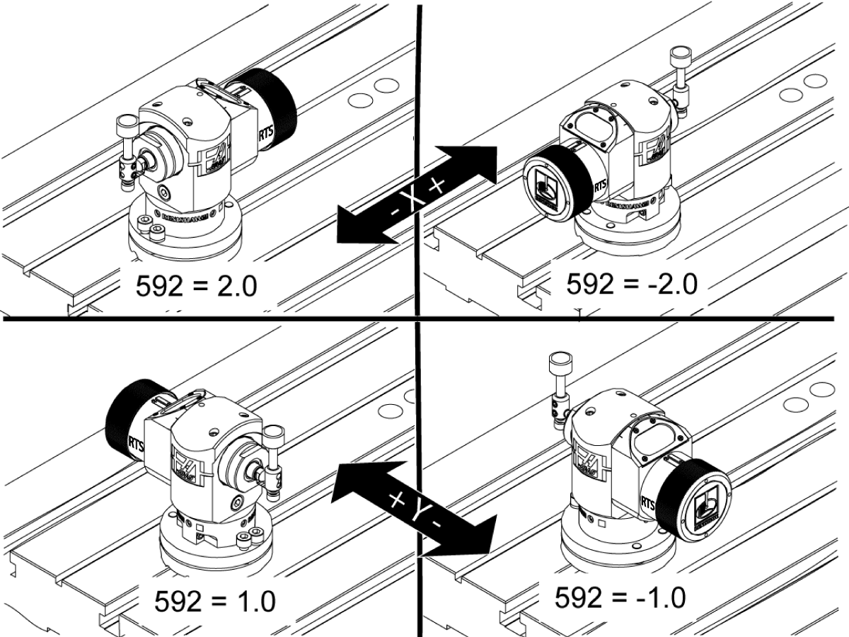
---installation/Renishaw-OTS-Rotate-Base.png)
---installation/Renishaw-OTS-598-Settings.png)