My Haas Welcome,
!
Haas Tooling MyHaas/HaasConnect Sign In Register Haas Tooling MyHaas/HaasConnect Sign Out Welcome, My Machines Latest Activity My Quotes My Account My Users Sign Out
Find Your Distributor
  1. Select Language
    1. English
    2. Deutsch
    3. Español - ES
    4. Español - MX
    5. Français
    6. Italiano
    7. Português
    8. Český
    9. Dansk
    10. Nederlands
    11. Magyar
    12. Polski
    13. Svenska
    14. Türkçe
    15. 中文
    16. Suomi
    17. Norsk
    18. الإنجليزية
    19. български
    20. Hrvatski
    21. Ελληνικά
    22. Română
    23. Slovenský
    24. Slovenščina
    25. 한국어
    26. 日本語
    27. Українська
  • machines Main Menu
    • Vertical Mills
      Vertical Mills
      Vertical Mills View All
      • Vertical Mills
      • VF Series
      • Universal Machines
      • VR Series
      • VP-5 Prismatic
      • Pallet-Changing VMCs
      • Mini Mills
      • Mold Machines
      • High-Speed Drill Centers
      • Drill/Tap/ Mill Series
      • Toolroom Mills
      • Pocket Mill
      • Compact Mills
      • Gantry Series
      • SR Sheet Routers
      • Extra-Large VMC
      • Double-Column Mills
      • 3+2 Positioning Machines
    • Multi-Axis Solutions
      Multi-Axis Solutions
      Multi-Axis Solutions View All
      • Multi-Axis Solutions
      • Y-Axis Lathes
      • 5-Axis Mills
    • Lathes
      Lathes
      Lathes View All
      • Lathes
      • ST Series
      • Dual-Spindle
      • Box Way Series
      • Toolroom Lathes
      • Chucker Lathe
      • Pocket Lathe
      • Haas Bar Feeders
    • Horizontal Mills
      Horizontal Mills
      Horizontal Mills View All
      • Horizontal Mills
      • 50-Taper
      • 40-Taper
    • Rotaries & Indexers
      Rotaries & Indexers
      Rotaries & Indexers View All
      • Rotaries & Indexers
      • Rotary Tables
      • Indexers
      • 5-Axis Rotaries
      • Extra-Large Rotaries
    • Special Series
      Special Series
      Special Series View All
      • Special Series
      • EU_Series_Redirect
    • Automation Systems
      Automation Systems
      Automation Systems View All
      • Automation Systems
      • Mill Automation
      • Lathe Automation
      • Automatic Parts Loaders
      • Automation Models
    • Desktop Machines
      Desktop Machines
      Desktop Machines View All
      • Desktop Machines
      • Desktop Mill
      • Desktop Lathe
      • Control Simulator, Standard
      • Control Simulator, Premium
    • Shop Equipment
      Shop Equipment
      Shop Equipment View All
      • Shop Equipment
      • Knee Mill
      • Haas Manual Lathes
      • Haas Saws
    • Fabrication Machines
      Fabrication Machines
      Fabrication Machines View All
      • Fabrication Machines
      • Laser Cutting Machines
      • CNC Press Brakes
    • QUICK LINKS Special Series  Special Series 
      EU SERIES EU SERIES BUILD & PRICE | PRICE LIST BUILD & PRICE | PRICE LIST In-Stock Machines In-Stock Machines WHAT’S NEW WHAT’S NEW YOUR FIRST CNC YOUR FIRST CNC
      SHOPPING TOOLS
      • Build & Price a Haas
      • Price List
      • Available Inventory
      • CNCA Financing
      WANT TO TALK TO SOMEONE?

      A Haas Factory Outlet (HFO) can answer your questions, and walk you through your best options.

      CONTACT YOUR DISTRIBUTOR >
  • Options Main Menu
    • The Haas Control Value Option Packages
      Value Option Packages
      Value Option Packages View All
      • Value Option Packages
    • Product Image Spindles
      Spindles
      Spindles View All
      • Spindles
    • Product Image Tool Changers
      Tool Changers
      Tool Changers View All
      • Tool Changers
    • Product Image 4th- | 5th-Axis
      4th- | 5th-Axis
      4th- | 5th-Axis View All
      • 4th- | 5th-Axis
    • Product Image Turrets & Live Tooling
      Turrets & Live Tooling
      Turrets & Live Tooling View All
      • Turrets & Live Tooling
    • Product Image Probing
      Probing
      Probing View All
      • Probing
    • Haas Chip & Coolant Management Chip & Coolant Management
      Chip & Coolant Management
      Chip & Coolant Management View All
      • Chip & Coolant Management
    • The Haas Control The Haas Control
      The Haas Control
      The Haas Control View All
      • The Haas Control
    • Product Image Product Options
      Product Options
      Product Options View All
      • Product Options
    • Product Image Tooling & Fixturing
      Tooling & Fixturing
      Tooling & Fixturing View All
      • Tooling & Fixturing
    • Product Image Workholding
      Workholding
      Workholding View All
      • Workholding
    • Product Image 5-Axis Solutions
      5-Axis Solutions
      5-Axis Solutions View All
      • 5-Axis Solutions
      • 5 Easy Steps to 5-Axis
    • QUICK LINKS Special Series  Special Series 
      EU SERIES EU SERIES BUILD & PRICE | PRICE LIST BUILD & PRICE | PRICE LIST In-Stock Machines In-Stock Machines WHAT’S NEW WHAT’S NEW YOUR FIRST CNC YOUR FIRST CNC
      SHOPPING TOOLS
      • Build & Price a Haas
      • Price List
      • Available Inventory
      • CNCA Financing
      WANT TO TALK TO SOMEONE?

      A Haas Factory Outlet (HFO) can answer your questions, and walk you through your best options.

      CONTACT YOUR DISTRIBUTOR >
  • Why Haas Main Menu
      Discover the Haas Difference
    • Why Haas
    • MyHaas
    • Education Community
    • Industry 4.0
    • Haas Certification
    • Customer Testimonials
  • Service Main Menu
      Welcome to Haas Service
      SERVICE HOME Operator’s Manuals How-To Procedures Troubleshooting Guides Preventive Maintenance Haas Parts Haas Tooling Videos
  • Videos Main Menu
  • Main Menu
    • View All
    • View All
    • View All
    • View All
      • HTEC Curriculum Support
      • Haas Value Option Packages (VOP) Journey
    • View All
      • Haas 10 kg Cobot Package
      • Cobot Kits
      • DC-1 Drill Center
      • CNC Sales News
      • Do More With Your Haas
    • View All
    • View All
      • contact-us-test
      • 4 - AUTOMATION SYSTEMS
      • Carousel-V2
      • expert test
      • Demo_Day_Trident-test
      • Link Test
      • image-sale-tag-test
      • article-list-test
      • Haas 25 kg Robot Package
      • test-algolia-page
    • View All
    • View All
    • View All
    • View All
      • calc-test
    • View All
    • QUICK LINKS Special Series  Special Series 
      EU SERIES EU SERIES BUILD & PRICE | PRICE LIST BUILD & PRICE | PRICE LIST In-Stock Machines In-Stock Machines WHAT’S NEW WHAT’S NEW YOUR FIRST CNC YOUR FIRST CNC
      SHOPPING TOOLS
      • Build & Price a Haas
      • Price List
      • Available Inventory
      • CNCA Financing
      WANT TO TALK TO SOMEONE?

      A Haas Factory Outlet (HFO) can answer your questions, and walk you through your best options.

      CONTACT YOUR DISTRIBUTOR >
  • Haas Tooling Main Menu
  • Haas Service Parts Main Menu

My Haas Welcome,
!
Haas Tooling MyHaas/HaasConnect Sign In Register Haas Tooling MyHaas/HaasConnect Sign Out Welcome, My Machines Latest Activity My Quotes My Account My Users Sign Out
Find Your Distributor
  1. Select Language
    1. English
    2. Deutsch
    3. Español - ES
    4. Español - MX
    5. Français
    6. Italiano
    7. Português
    8. Český
    9. Dansk
    10. Nederlands
    11. Magyar
    12. Polski
    13. Svenska
    14. Türkçe
    15. 中文
    16. Suomi
    17. Norsk
    18. الإنجليزية
    19. български
    20. Hrvatski
    21. Ελληνικά
    22. Română
    23. Slovenský
    24. Slovenščina
    25. 한국어
    26. 日本語
    27. Українська
×

Search Results

Web Pages

Images

    • <
    • 1
    • >

8 - Haas Cobot - Area Scanner Installation

Haas Cobot Package - Operator's/Service Manual


  • 0 - Haas Cobot - Table of Contents
  • 1 - Haas Cobot - Introduction
  • 2 - Haas Cobot - Legal Information
  • 3 - Haas Cobot - Safety
  • 4 - HC5 - Installation
  • 5 - HC10 - Installation
  • 6 - HC15 - Installation
  • 7 - HC30 - Installation
  • 7 - Haas Cobot - Fence/Interlock Installation
  • 8 - Haas Cobot - Area Scanner Installation
  • 9 - Haas Cobot - Light Curtain Installation
  • 11 - Haas Cobot - Operation
  • 12 - Haas Cobot - Maintenance
  • 13 - Haas Cobot - Troubleshooting

Go To :

  • 8.1 Haas Cobot - Area Scanner Installation
  • 8.2 Haas Cobot - Area Scanner Software Setup
  • 8.3 Haas Cobot - Area Scanner Troubleshooting Guide
Recently Updated

Area Scanner - Installation


AD0687

Introduction

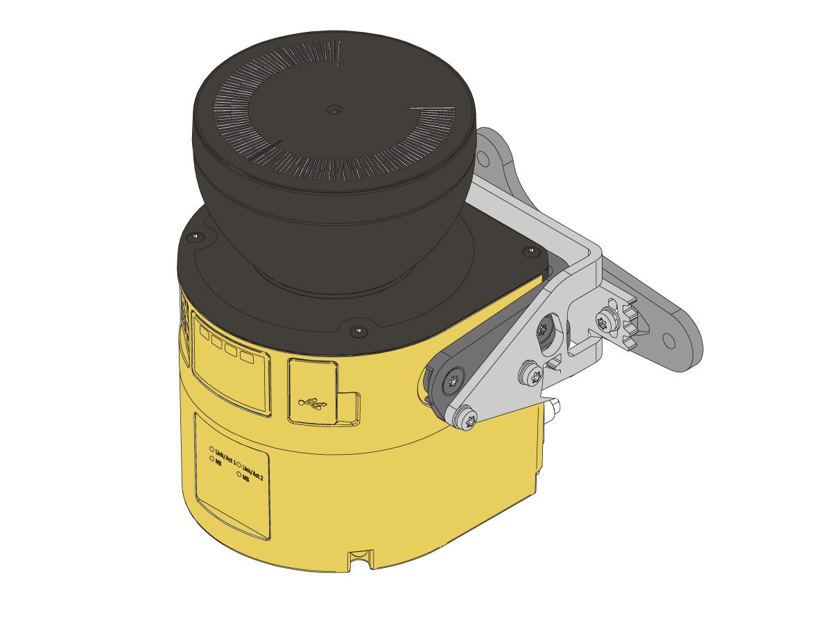
The safety area scanner can be used to protect the user from the robot without needing to use an interlocking fence or light curtain.

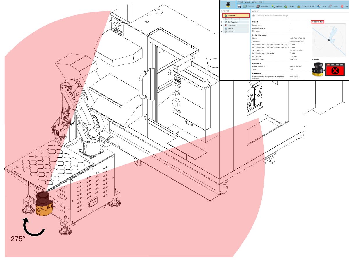
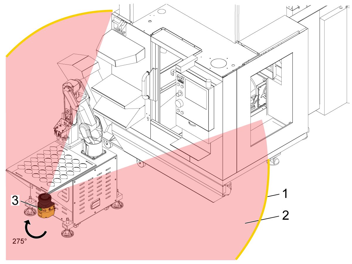
The safety area scanner sends out lasers in ~275° that scan the nearby area. When an object is detected within the configured protective field, a signal is sent back to the machine to stop.

Machine Requirements:

  • 32-9010 HRP-1 18' ELEC SAFETY INTF BOX
  • 32-9018 CBT/HRP-2/3 18' ELECT SAFETY INTF BOX

 IMPORTANT: Without the area scanner compatible interface box, the area scanner won't be connected to the machine. These upgraded interface boxes were added to all COBOT packages & HRP-1/2/3 packages built after 07/10/2023. If the machine's interface box was built before these dates, refer to the Robot Safety Device Interface Box Installation - AD0703 procedure for more information. 

Software Requirements:

  • 100.23.000.1120 version or higher 

The Area Scanner Kit (08-1897) Includes the following Components:

  • 09-0625 Area Scanner Cable
  • 09-0626 Area Scanner Floor Mount
  • 09-0627 Laser Area Scanner

Risk Assessment

IMPORTANT: Before any installation, an appropriate risk-assessment must be performed and appropriate safety requirements must be met. 

Installation

1

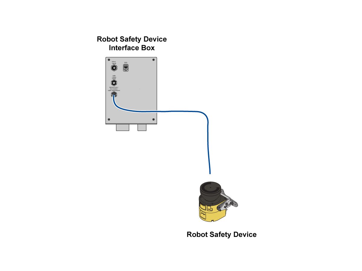
Plug the area scanner into the power source--either the machine's interface box if an integrated area scanner OR the wall's outlet if a stand alone area scanner. 

2

Find the best location for the area scanner where it can detect it's maximum range ~275°. Make sure there are no blind spots. 

NOTE: To make sure that area scanner location is good, power on the area scanner and view it's Measured Data information under the Overview tab. For information on downloading the software, refer to the Area Scanner - Software Setup - AD0688 procedure. 

Mark the area scanner location.

Unplug the area scanner from the power source.

3

Find the best height for the area scanner where it can detect it's maximum range while preventing someone to crawl beneath or stop over. The height location is based on where you want the 2D scan plane to take place. 

 NOTE: Typically, the desired height location is around 300 mm above the ground causing the scan plane to be at calf level. Avoid too low/high of a height causing the scan plane to be at ankle/stomach level.

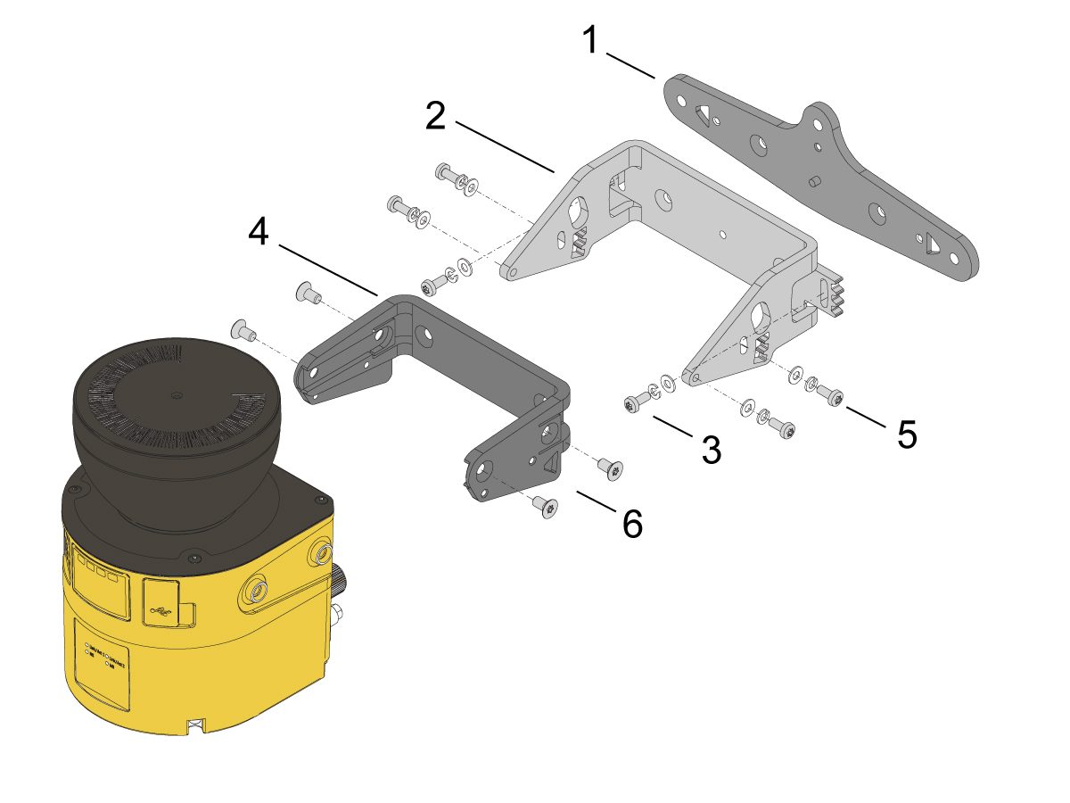
Bolt the holding plate [1] onto the surface at the desired location and height. Make sure the holding plate [1] is oriented correctly.

Bolt the alignment bracket [2] onto the holding plate [1] with screws [3].

Bolt the mounting bracket [4] onto the alignment bracket [2] with screws [5]. 

Push the safety area scanner into the mounting bracket [4]. Bolt with screws [6].

4

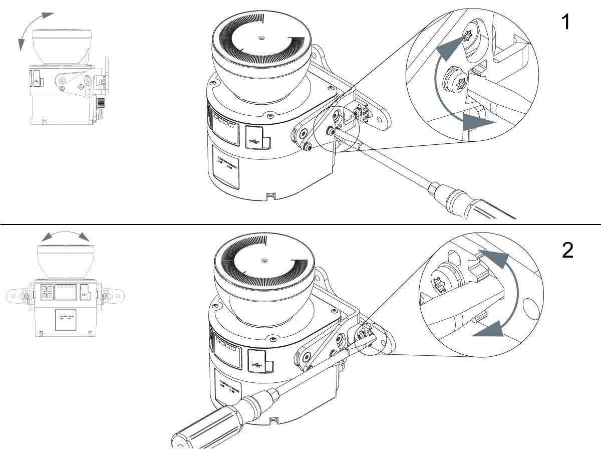
Align the safety laser scanner using a slotted screwdriver for fine alignment. 

Location [1] shows how to adjust alignment in the transverse axis.

Location [2] shows how to adjust alignment in the depth axis. 

Once alignment is set, torque the screws. For torque values, refer to Haas Fastener Torque Specifications for more information. 

5

Once the area scanner is mounted and aligned in the desired location, configure the protective field by following the Area Scanner - Software Setup - AD0688 procedure for more information. 

 IMPORTANT: The area scanner will need to be re-configured after relocating the area scanner or anything inside its protective field. 

RJH-XL Remote E-Stop Installation

1

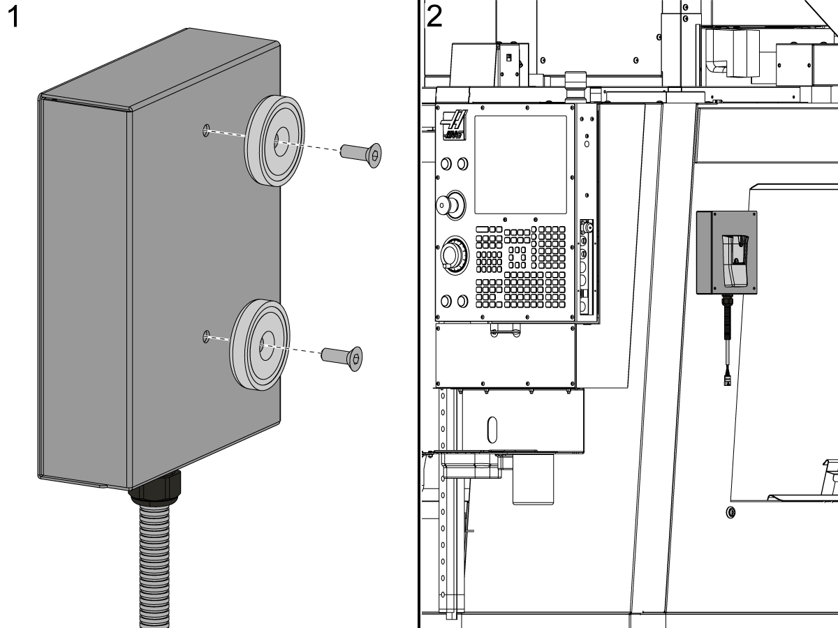
If the Control Pendant is outside of the area scanner field the RJH-XL can mounted on the pendant as normal.

If the the Control Pendant is inside the area scanner field the magnets that come in the HRP install kit can be installed on the RJH-XL holster [1] and be mounted on the side of the machine [2].

Follow the directions below to install the RJH-XL.

RJH-XL Installation
Recently Updated

Area Scanner - Software Setup


AD0688

Introduction

This procedure will show how to set this protective field and configure the area scanner properly.

IMPORTANT: DO NOT OPERATE THE ROBOT UNTIL YOU HAVE PROPERLY CONFIGURED AND TESTED THE OPERATION OF THE SAFETY DEVICE.

For more information directly on the SICK Safety Area Scanner, refer to the SICK microScan3 Safety Laser Scanner manual for more information. 

NOTE: For any troubleshooting information, refer to the Area Scanner - Troubleshooting Guide. 

Machine Requirements:

  • 32-9010 HRP-1 18' ELEC SAFETY INTF BOX
  • 32-9018 CBT/HRP-2/3 18' ELECT SAFETY INTF BOX

 IMPORTANT: Without the area scanner compatible interface box, the area scanner won't be connected to the machine.These upgraded interface boxes were added to all COBOT packages & HRP-1/2/3 packages built after 07/10/2023. If the machine's interface box was built before these dates, refer to the Robot Safety Device Interface Box Installation - AD0703 procedure for more information. 

Software Requirements:

  • 100.23.000.1120 version or higher

IMPORTANT: The area scanner will need to be re-configure after relocating the area scanner or anything inside its protective field. 

Risk Assessment

IMPORTANT: Before any installation, an appropriate risk-assessment must be performed and appropriate safety requirements must be met. 

Download Safety Designer Software

Download Safety Designer installation file on to a computer. This is the software used to configure the area scanner's protective field. 

IMPORTANT: The Safety Designer software requires Window 10 operating system.  

Extract the installation file. 

Open the installation file and complete the downloading process. 

Setup Tutorial

The following service video will get you comfortable with the Safety Designer software and show how to configure the SICK microScan 3 area scanner.

  NOTE:  This  service video is for reference only and does not replace the written procedure. 

The following service video will give a demonstration of configuring a protective field for the area scanner through Safety Designer.  

  NOTE:  This  service video is for reference only and does not replace the written procedure. 

First Power Up

1

Make sure that the area scanner is mounted into the desire location where the area scanner can view it's maximum range of ~275°. 

IMPORTANT: If area scanner isn't mounted yet, refer to the Area Scanner - Installation - AD0687 procedure for more information. 

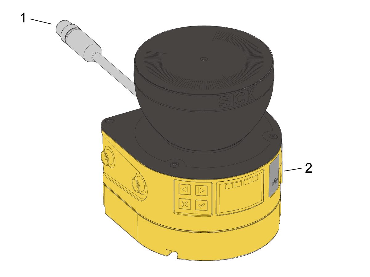
Plug the area scanner connector [1] into the power source--either the wall if a stand alone area scanner OR the machine's interface box if an integrated area scanner. 

Plug the micro USB cable from the area scanner [2] into the computer. 

2

Once powered, the area scanner's LED screen will turn yellow and say "No Configuration".

This will remain until the factory setting password is reset. Refer to the following video to reset the password.

The factory setting password is "SICKSAFE".

NOTE: This password is case sensitive. 

Setup

1

Using Safety Designer, click on New Project. 

Click Connect. 

NOTE: After a connection is established once between the area scanner and computer, click on Search for Devices next time.

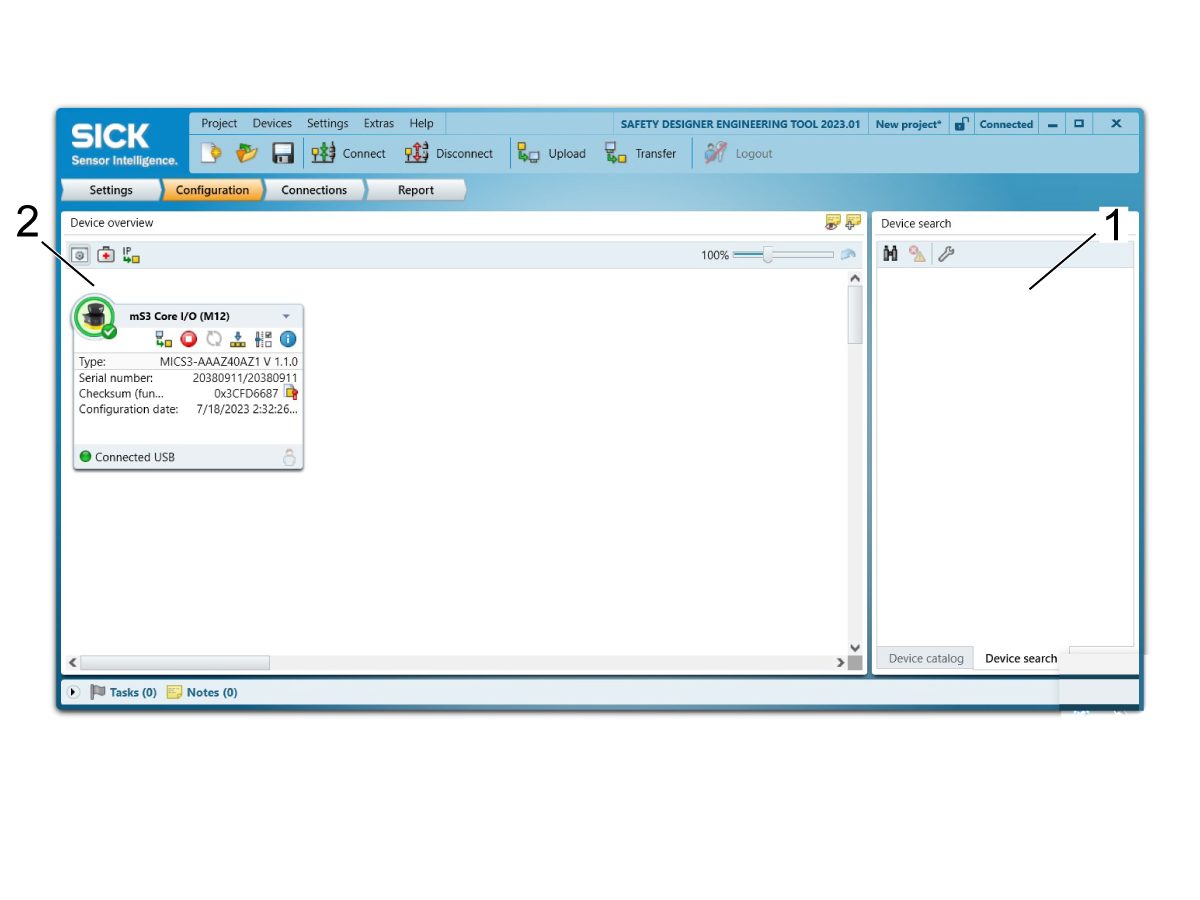
Once the safety designer has established a connection with the area scanner, an icon of the connected area scanner should pop up on the right under Device Search [1]. Double click on the icon to make a connection. 

Now an icon of the connected area scanner should pop up on the left under Device Overview [2]. Double click on the icon to open the device window. 

2

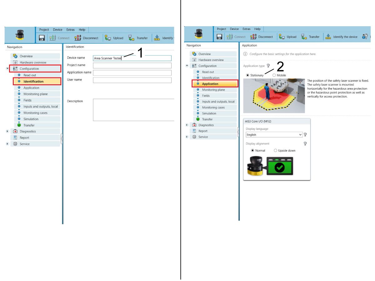
Click Configuration on the left side Navigation menu. 

Under Configuration, click on Identification. Insert a name [1] for the area scanner here if desired. 

Click on Application to chose between Stationary or Mobile [2]. For machining purposes, make sure that the application type is set to Stationary. 

Select the desired language. 

3

Click on Monitoring Plane to set a 2D horizontal or vertical monitoring plane [1]. In this case, a horizontal monitoring plane is the most common monitoring for machining applications.

 NOTE: If a vertical monitoring plane is used, then reference contour monitoring [2] is required. For more information, refer to page 84 on the SICK service manual.

Object resolution [3] sets the minimum size that the area scanner can detect. With a horizontal monitoring plane, the object resolution should be set around 50 to 70 mm. With a vertical monitoring plane, the object resolution should be set around 150 mm. 

Multiple sampling [4] sets the amount of times an object must be scanned by the area scanner before reacting. A higher multiple sampling reduces the likelihood that anything unwanted is detected such as insects, dust, etc. For stationary applications, there is a recommended multiple sampling of x2 under clean conditions whereas there is a recommended multiple sampling of x8 under dirty conditions. Play around within this range to find the amount that reacts the best. 

Scan cycle time [5] effects the response time of the area scanner. A normal scan cycle time of 40 ms is used for full protective field range whereas a fast scan cycle time of 30 ms is used for small protective field range with an even shorter response time. Typically, the normal scan time is selected. 

Additional interference protection [6] takes into account if other area scanners are present. Mode 1 should be selected when using only one area scanner on the machine. 

4

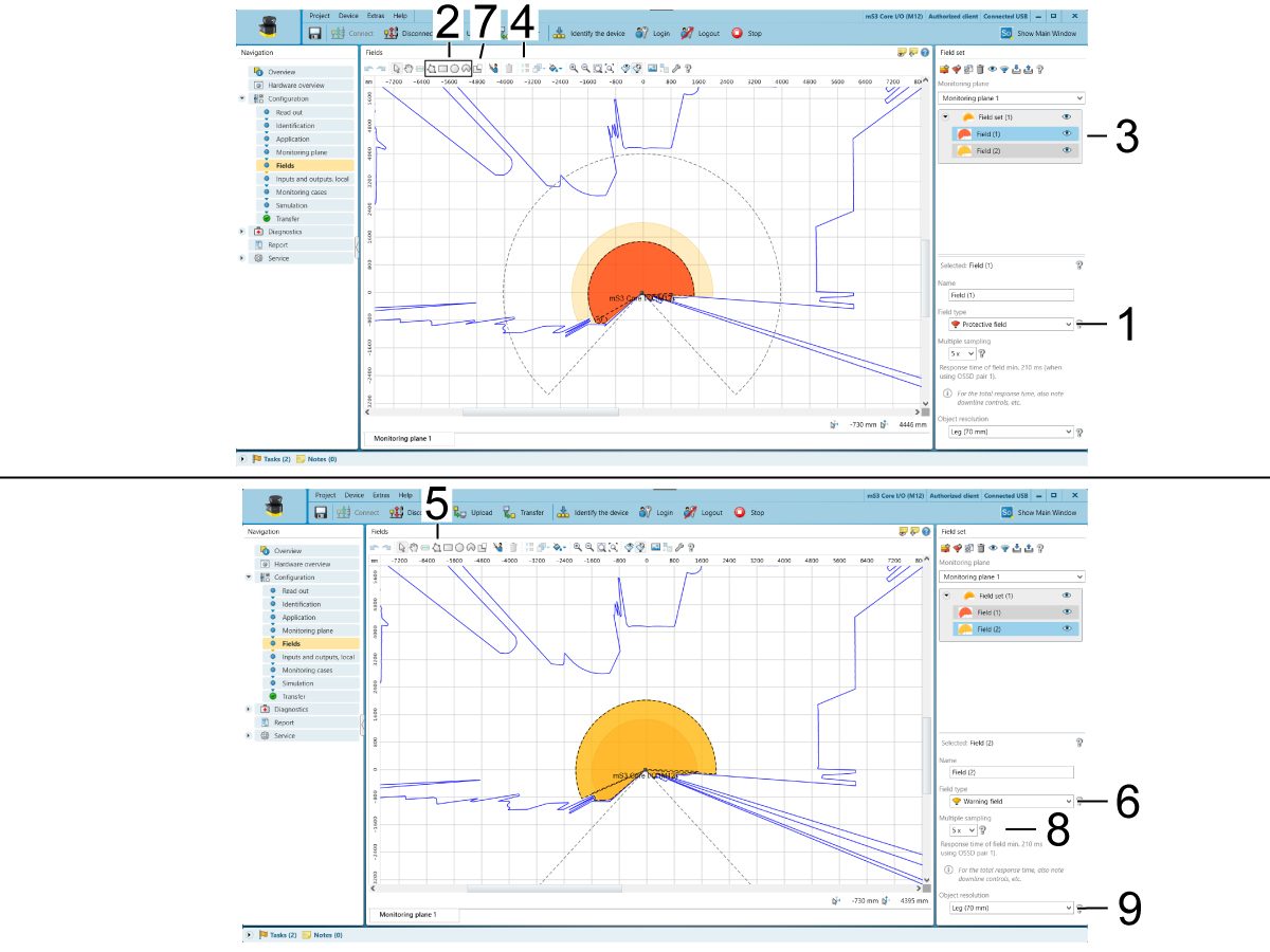
Click on Fields to set the protective field [1] that triggers the safety area scanner and stops robot motion. Using the drawing tools [2], you can draw the desired field set. Multiple fields can be configured in the same field set [3] to achieve the proper size and shape.

NOTE: For more accuracy, assign coordinates [4] or use the polygon tool [5].

Another field type is a warning field [6]. This field only triggers the yellow LED on the area scanner and doesn't stop robot motion. 

 IMPORTANT: Make sure to always have a protective field [1] set as this is what stops the robot motion. Warning fields [6] can be helpful, but not always needed, as it will never trigger the light curtain causing the robot to always stay running even in unsafe states. 

A masked area [7] can be drawn into the field. This represents an area that does not trigger the safety area scanner. 

Each field can be individually configured by changing the multiple sampling [8] and object resolution [9]. 

5

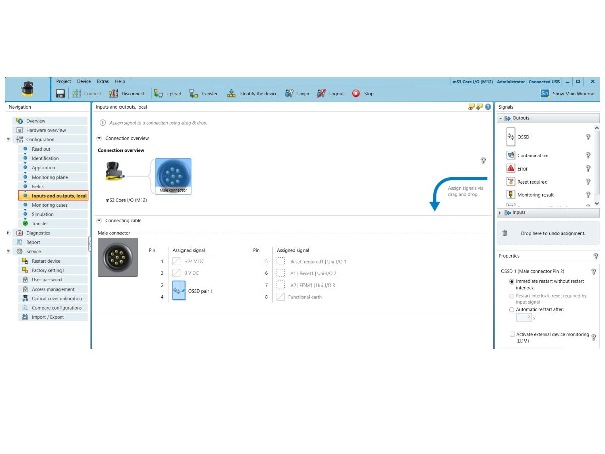
Click on Inputs and Outputs, Local to configure the Area Scanners universal inputs/outputs. There are 3 avaliable universal inputs/outputs.

For a basic machining set up, there is no need to configure any universal inputs/outputs. Leave this page blank, unless wanting to make a special configuration. 

NOTE: Make sure Pin 2 & 4 are always configured to OSSD pair 1. 

6

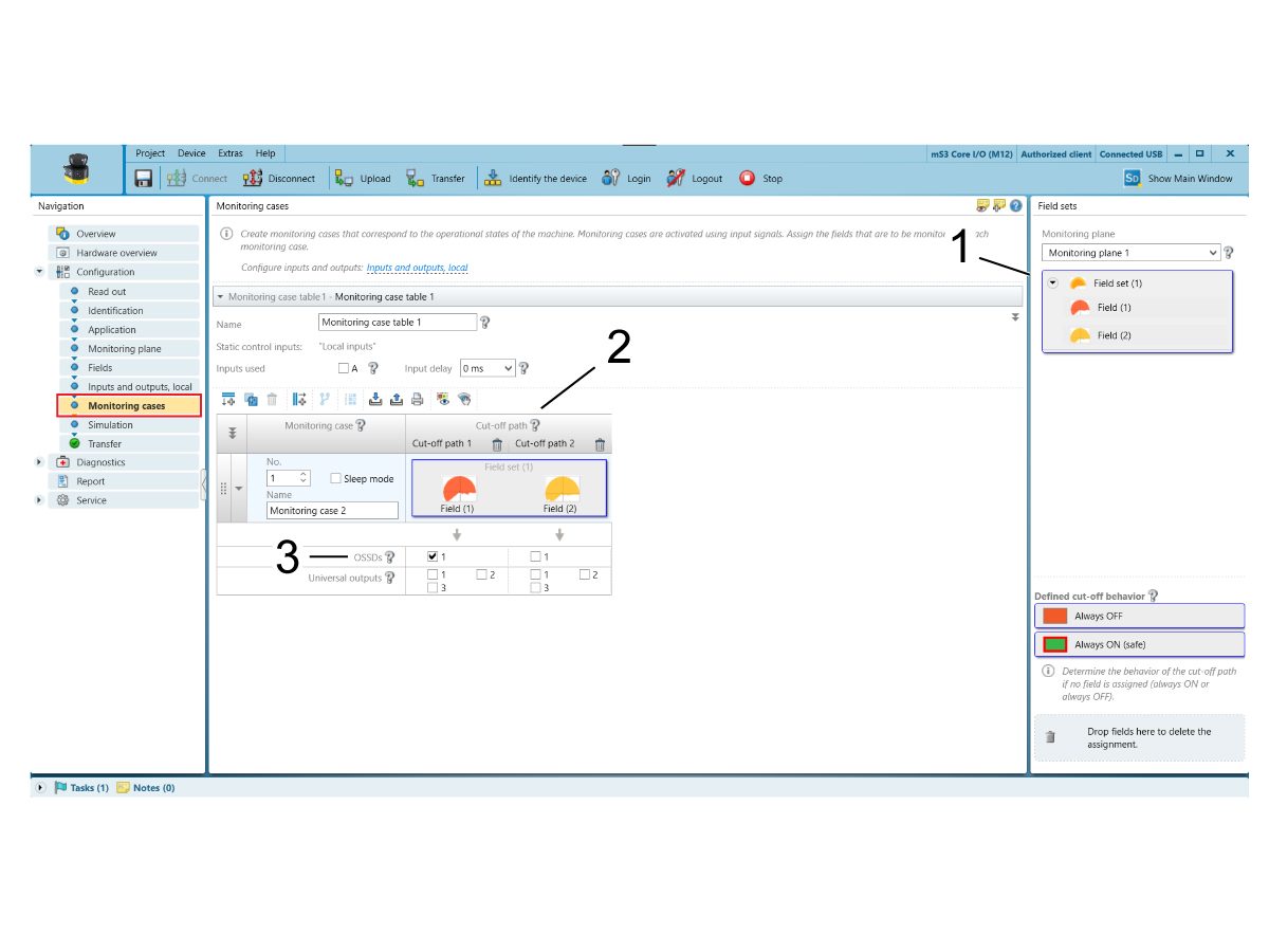
Click on Monitoring Cases to applies the field set to the area scanner.

Drag Monitoring Plane 1 field set [1] into Monitoring Case 1's cut off path 1 [2]. 

Check the OSSD box [3] below the protective field. This turns the output safety switching device ON when the protective field is triggered. With the output safety switching device ON, the robot motion will stop. 

7

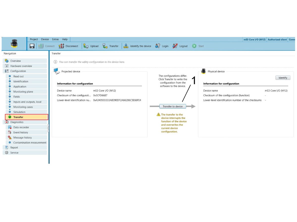
Click on Transfer to move the configuration from the computer software to the safety area scanner. 

Click Transfer to Device [1]. 

A pop up appears asking if the device can enter Test Mode. Click Yes. 

Enter the Authorized client's password as needed. 

Read through the configuration report and Verify. 

8

Tape [1] the safety area scanner protective field [2] onto the floor.

Test the configured safety area scanner. 

Make sure that the green LED above the safety area scanner display screen [3] shines when outside the protective field and the red LED shines when inside the protective field. 

NOTE: If the actual protective field doesn't match the desired protective field—edit the protective field, insert the protective field into Monitoring Case 1's cut off path and transfer the configuration over again. Play around until the desired protective field is reached. 

IMPORTANT: Make sure that there are no blind spots in the protective field.

Remove the micro USB from the area scanner to computer.

9

With the machine in service mode, go to Parameters > Factory tab.

Set parameter 2191 [694] LIGHT CURTAIN TYPE to LC_TYPE_1.

NOTE: Machines with software version 100.20.000.1010 or higher will need to set parameter 2192 [:] LIGHT CURTAIN TRIGGER THRESHOLD to 0. 

Set the setting 376 LIGHT CURTAIN ENABLED to ON. 


Recently Updated

Area Scanner - Troubleshooting Guide


TG0028

Introduction

This troubleshooting guide will show you how to troubleshoot the SICK safety area scanner configured with a Haas machine.

 NOTE: For area scanner installation onto a Haas machine, refer to the Area Scanner - Installation - AD0687 and Area Scanner - Software Setup - AD0688 procedure for more information. 

IMPORTANT: For more information directly on the SICK Safety Area Scanner, refer to the SICK microScan3 Safety Laser Scanner manual for more information. 

IMPORTANT: DO NOT OPERATE THE ROBOT UNTIL YOU HAVE PROPERLY CONFIGURED AND TESTED THE OPERATION OF THE SAFETY DEVICE.

Symptom Table

SYMPTOM POSSIBLE CAUSE CORRECTIVE ACTION

The Safety Device Icon does not clear when the Area Scanner is not tripped.


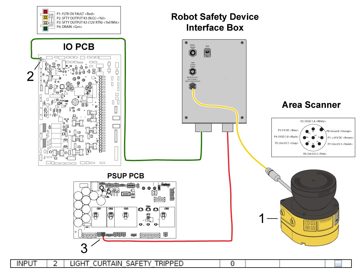
The electrical connections are not correct. Check the connections from the Area Scanner to I/O PCB. Refer to the Electrical Schematic section below. 
There is something interferring the Area Scanner protective field. Remove the object interferring the Area Scanner protective field.

The protective field's response time is too slow.

The area scanner is scanning the object inside the protective field too many times before reacting.  Go to Configuration > Monitoring Plane to lower the multiple sampling. 
The protective field can detect large objects, but not smaller objects.  The object resolution is set too high--this defines the minimum size that an object must be to be detected by the protective field.  Go to Configuration > Monitoring Plane to lower the object resolution.
Area scanner will not connect with the computer. On Safety Designer under Configuration and then Read Out, verify that checksums of both area scanner and computer software are the same. If they don't, the configuration of the two devices does not match up. 


Update the software version of Safety Designer. 

Alarms

ALARM DISPLAY ALARM MEANING OSSD State¹

The protective field is clear.  ON
The protective field is not clear.  OFF
The area scanner has a fault. The specific fault type is shown with 2 characters on the LED display. To learn about each fault type, refer to page 125 - 127 of the SICK Safety Area Scanner manual.  OFF
The area scanner lens is 20% contaminated. Clean the lens with lens cloth or anti-static plastic cleaner. ON
The area scanner lens is 35% contaminated. Clean the lens with lens cloth or anti-static plastic cleaner. OFF
All safety function have stopped. Restart the area scanner. OFF
The device is not configured.  OFF
  1. NOTE: The OSSD state tells whether the output safety switching device is ON or OFF. When the protective field is triggered, the OSSD turns ON and the robot motion will stop. When the protective field is clear, the OSSD turns OFF and the robot motion will continue. 

Display Screen

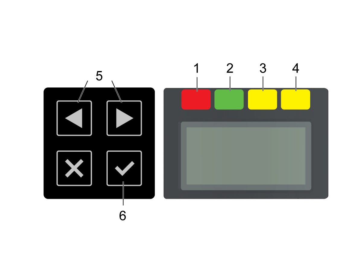
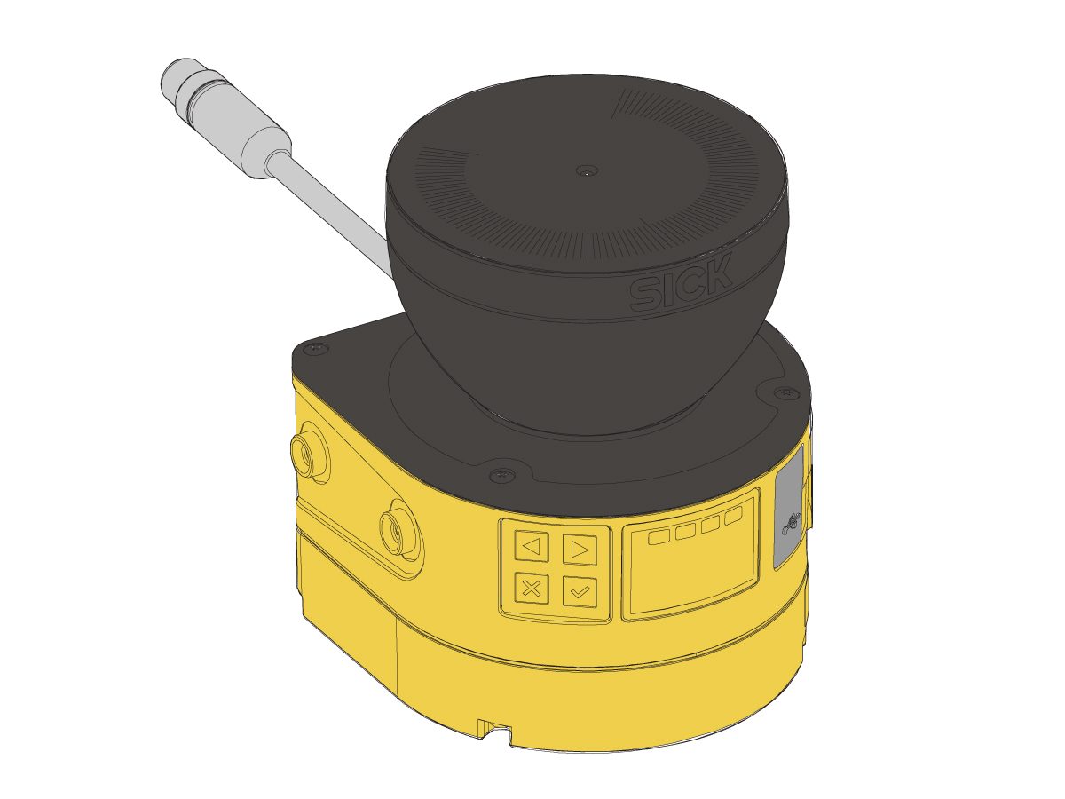
There are four LED lights located directly above the display screen that shine depending on the state of the area scanner:

[1] The red LED represents when the OSSD pair is in the OFF state.

[2] The green LED represents when the OSSD pair is in the ON state. 

[3] The left yellow LED represents when the warning field is interrupted.

[4] The right yellow LED flashes when the restart interlock has been triggered. The restart interlock is not an option on machines, unless personally configured otherwise. 

There are four buttons located directly left of the display screen that can change simple setting and show more information about a specific alarm. To see more information in text form, press the arrows [5] or check [6] button to navigate. 

NOTE: These buttons [5, 6] and the display screen are useful tools when trying to troubleshoot an alarm. 

The display screen can also show device information of it's hardware, device code, firmware version, configurations and more. 

Diagnostics

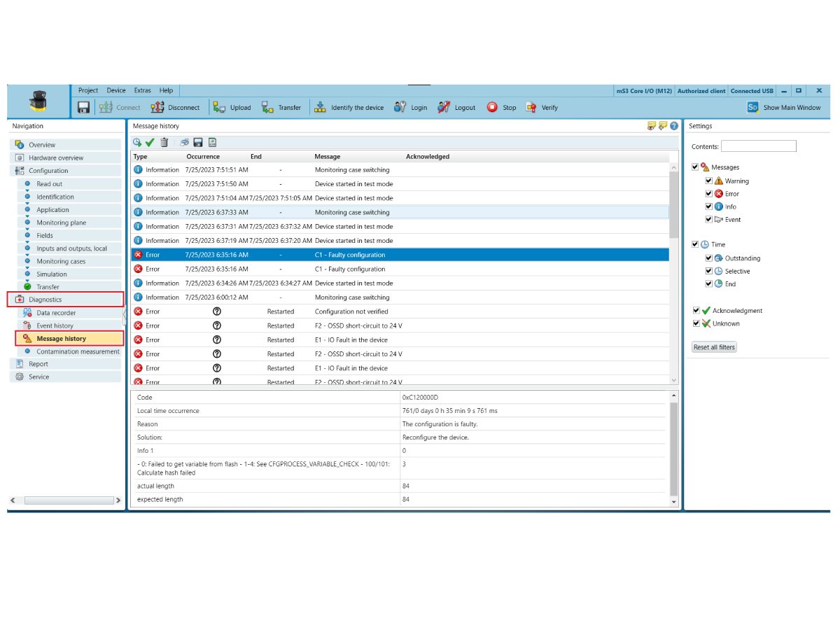
Under Diagnostics, click on Message History to view recorded past data from the area scanner.

This shows previous error messages, warnings, etc. that provide more information on the specific problem by giving information on the time occurrence, reason for the error, solution, and any other relevant information. This page can be helpful when troubleshooting the area scanner's faults.

Electrical Schematic

 NOTE: Connect the area scanner cable 09-0625 from the area scanner [1] to the machine's interface box (or wall's outlet if stand alone area scanner) with the M12 connection. 

Feedback

Recently Viewed Items

You Have No Recently Viewed Items Yet

Feedback
Haas Logo

Haas Delivered Price

This price includes shipping cost, export and import duties, insurance, and any other expenses incurred during shipping to a location in France agreed with you as a buyer. No other mandatory costs can be added to the delivery of a Haas CNC Product.

KEEP UP WITH THE LATEST HAAS TIPS AND TECHNOLOGY...

Sign up now!   

HAAS TOOLING ACCEPTS THE FOLLOWING:

  • Service & Support
  • Owners
  • Request Service
  • Operator Manuals
  • Haas Parts
  • Rotary Repair Request
  • Pre-Install Guides
  • Shopping Tools
  • Build & Price a New Haas
  • Available Inventory
  • The Haas Price List
  • CNCA Financing
  • About Haas
  • Accessibility Statement
  • DNSH Statement
  • Export Compliance
  • Careers
  • Certifications & Safety
  • Contact Us
  • History
  • Terms & Conditions
  • Haas Tooling Terms & Conditions
  • Privacy
  • Warranty
  • Haas Community
  • Haas Certification Program
  • Haas Motorsports
  • Gene Haas Foundation
  • Haas Technical Education Community
  • Events
  • Join the Conversation
  • Facebook
  • X
  • Flickr
  • YouTube
  • LinkedIn
  • Instagram
  • TikTok
© 2026 Haas Automation, Inc – CNC Machine Tools
This site is protected by reCAPTCHA and the Google Privacy Policy and Terms of Service apply.

2800 Sturgis Rd., Oxnard, CA 93030
Toll Free: (888) 817-4446 / Fax: 805-278-8554