My Haas Welcome,
!
Haas Tooling MyHaas/HaasConnect Sign In Register Haas Tooling MyHaas/HaasConnect Sign Out Welcome, My Machines Latest Activity My Quotes My Account My Users Sign Out
Find Your Distributor
  1. Select Language
    1. English
    2. Deutsch
    3. Español - España
    4. Español - México
    5. Français
    6. Italiano
    7. Português
    8. Český
    9. Dansk
    10. Nederlands
    11. Magyar
    12. Polski
    13. Svenska
    14. Türkçe
    15. 中文
    16. Suomi
    17. Norsk
    18. الإنجليزية
    19. български
    20. Hrvatski
    21. Ελληνικά
    22. Română
    23. Slovenský
    24. Slovenščina
    25. 한국어
    26. 日本語
    27. Українська
  • machines Main Menu
    • Vertical Mills
      Vertical Mills
      Vertical Mills View All
      • Vertical Mills
      • VF Series
      • Universal Machines
      • VR Series
      • VP-5 Prismatic
      • Pallet-Changing VMCs
      • Mini Mills
      • Mold Machines
      • High-Speed Drill Centers
      • Drill/Tap/ Mill Series
      • Toolroom Mills
      • Pocket Mill
      • Compact Mills
      • Gantry Series
      • SR Sheet Routers
      • Extra-Large VMC
      • Double-Column Mills
      • 3+2 Positioning Machines
    • Multi-Axis Solutions
      Multi-Axis Solutions
      Multi-Axis Solutions View All
      • Multi-Axis Solutions
      • Y-Axis Lathes
      • 5-Axis Mills
    • Lathes
      Lathes
      Lathes View All
      • Lathes
      • ST Series
      • Dual-Spindle
      • Box Way Series
      • Toolroom Lathes
      • Chucker Lathe
      • Haas Bar Feeders
    • Horizontal Mills
      Horizontal Mills
      Horizontal Mills View All
      • Horizontal Mills
      • 50-Taper
      • 40-Taper
    • Rotaries & Indexers
      Rotaries & Indexers
      Rotaries & Indexers View All
      • Rotaries & Indexers
      • Rotary Tables
      • Indexers
      • 5-Axis Rotaries
      • Extra-Large Rotaries
    • Special Series
      Special Series
      Special Series View All
      • Special Series
      • EU_Series_Redirect
    • Automation Systems
      Automation Systems
      Automation Systems View All
      • Automation Systems
      • Mill Automation
      • Lathe Automation
      • Automatic Parts Loaders
      • Automation Models
    • Desktop Machines
      Desktop Machines
      Desktop Machines View All
      • Desktop Machines
      • Desktop Mill
      • Desktop Lathe
      • Control Simulator, Standard
      • Control Simulator, Premium
    • Shop Equipment
      Shop Equipment
      Shop Equipment View All
      • Shop Equipment
      • Knee Mill
      • Haas Manual Lathes
      • Haas Saws
    • Fabrication Machines
      Fabrication Machines
      Fabrication Machines View All
      • Fabrication Machines
      • Laser Cutting Machines
      • CNC Press Brakes
    • QUICK LINKS Special Series  Special Series 
      EU SERIES EU SERIES BUILD & PRICE | PRICE LIST BUILD & PRICE | PRICE LIST In-Stock Machines In-Stock Machines WHAT’S NEW WHAT’S NEW YOUR FIRST CNC YOUR FIRST CNC
      SHOPPING TOOLS
      • Build & Price a Haas
      • Price List
      • Available Inventory
      • CNCA Financing
      WANT TO TALK TO SOMEONE?

      A Haas Factory Outlet (HFO) can answer your questions, and walk you through your best options.

      CONTACT YOUR DISTRIBUTOR >
  • Options Main Menu
    • The Haas Control Value Option Packages
      Value Option Packages
      Value Option Packages View All
      • Value Option Packages
    • Product Image Spindles
      Spindles
      Spindles View All
      • Spindles
    • Product Image Tool Changers
      Tool Changers
      Tool Changers View All
      • Tool Changers
    • Product Image 4th- | 5th-Axis
      4th- | 5th-Axis
      4th- | 5th-Axis View All
      • 4th- | 5th-Axis
    • Product Image Turrets & Live Tooling
      Turrets & Live Tooling
      Turrets & Live Tooling View All
      • Turrets & Live Tooling
    • Product Image Probing
      Probing
      Probing View All
      • Probing
    • Haas Chip & Coolant Management Chip & Coolant Management
      Chip & Coolant Management
      Chip & Coolant Management View All
      • Chip & Coolant Management
    • The Haas Control The Haas Control
      The Haas Control
      The Haas Control View All
      • The Haas Control
    • Product Image Product Options
      Product Options
      Product Options View All
      • Product Options
    • Product Image Tooling & Fixturing
      Tooling & Fixturing
      Tooling & Fixturing View All
      • Tooling & Fixturing
    • Product Image Workholding
      Workholding
      Workholding View All
      • Workholding
    • Product Image 5-Axis Solutions
      5-Axis Solutions
      5-Axis Solutions View All
      • 5-Axis Solutions
      • 5 Easy Steps to 5-Axis
    • QUICK LINKS Special Series  Special Series 
      EU SERIES EU SERIES BUILD & PRICE | PRICE LIST BUILD & PRICE | PRICE LIST In-Stock Machines In-Stock Machines WHAT’S NEW WHAT’S NEW YOUR FIRST CNC YOUR FIRST CNC
      SHOPPING TOOLS
      • Build & Price a Haas
      • Price List
      • Available Inventory
      • CNCA Financing
      WANT TO TALK TO SOMEONE?

      A Haas Factory Outlet (HFO) can answer your questions, and walk you through your best options.

      CONTACT YOUR DISTRIBUTOR >
  • Why Haas Main Menu
      Discover the Haas Difference
    • Why Haas
    • MyHaas
    • Education Community
    • Industry 4.0
    • Haas Certification
    • Customer Testimonials
  • Service Main Menu
      Welcome to Haas Service
      SERVICE HOME Operator’s Manuals How-To Procedures Troubleshooting Guides Preventive Maintenance Haas Parts Haas Tooling Videos
  • Videos Main Menu
  • Main Menu
    • View All
    • View All
    • View All
    • View All
      • HTEC Curriculum Support
      • Haas Value Option Packages (VOP) Journey
    • View All
      • Haas 10 kg Cobot Package
      • Cobot Kits
      • DC-1 Drill Center
      • CNC Sales News
      • Do More With Your Haas
    • View All
    • View All
      • contact-us-test
      • 4 - AUTOMATION SYSTEMS
      • Carousel-V2
      • expert test
      • Demo_Day_Trident-test
      • Link Test
      • image-sale-tag-test
      • article-list-test
      • Haas 25 kg Robot Package
      • test-algolia-page
    • View All
    • View All
    • View All
    • View All
      • calc-test
    • View All
    • QUICK LINKS Special Series  Special Series 
      EU SERIES EU SERIES BUILD & PRICE | PRICE LIST BUILD & PRICE | PRICE LIST In-Stock Machines In-Stock Machines WHAT’S NEW WHAT’S NEW YOUR FIRST CNC YOUR FIRST CNC
      SHOPPING TOOLS
      • Build & Price a Haas
      • Price List
      • Available Inventory
      • CNCA Financing
      WANT TO TALK TO SOMEONE?

      A Haas Factory Outlet (HFO) can answer your questions, and walk you through your best options.

      CONTACT YOUR DISTRIBUTOR >
  • Haas Tooling Main Menu
  • Haas Service Parts Main Menu

My Haas Welcome,
!
Haas Tooling MyHaas/HaasConnect Sign In Register Haas Tooling MyHaas/HaasConnect Sign Out Welcome, My Machines Latest Activity My Quotes My Account My Users Sign Out
Find Your Distributor
  1. Select Language
    1. English
    2. Deutsch
    3. Español - España
    4. Español - México
    5. Français
    6. Italiano
    7. Português
    8. Český
    9. Dansk
    10. Nederlands
    11. Magyar
    12. Polski
    13. Svenska
    14. Türkçe
    15. 中文
    16. Suomi
    17. Norsk
    18. الإنجليزية
    19. български
    20. Hrvatski
    21. Ελληνικά
    22. Română
    23. Slovenský
    24. Slovenščina
    25. 한국어
    26. 日本語
    27. Українська
×

Search Results

Web Pages

Images

    • <
    • 1
    • >

VMC - Ballscrew - 32mm - Horizontal Plane - Replacement

Service Home How To Procedures VMC - Ballscrew - 32mm - Horizontal Plane - Replacement
Recently Updated Last updated: 08/11/2025

VMC - Ballscrew - 32mm - Horizontal Plane - Replacement


AD0861

Revision B - 08/2025

VMC - Ballscrew - 32mm - Horizontal Plane - Replacement

- Jump to Section - 1. Introduction 2. Removal- Ballscrew Motor (4 steps) 3. Removal- Ballscrew (7 steps) 4. Installation- Ballscrew (5 steps) 5. Installation- Ballscrew Motor (5 steps) Back to Top

Introduction

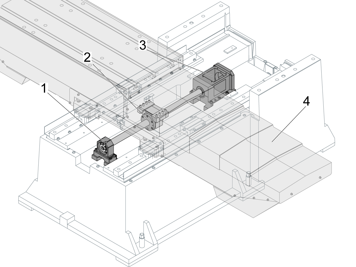
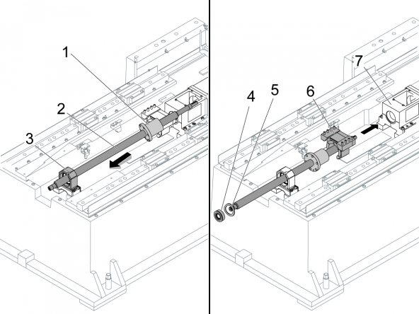
This procedure tells you how to replace a horizontal-plane ballscrew. This procedure shows a 32-mm ballscrew for the Y-Axis of a vertical machine.
[1] Support-bearing housing
[2] Ballnut
[3] Motor housing
 
Note: To let you see the inner parts, this procedure does not show the saddle assembly [4]. Do not remove the saddle assembly to do this procedure.
 
Prerequisites:
  1. Remove the Y-Axis waycovers.
  2. Lubricate the new ballscrew. Refer to Lubricant Table for Haas Machine Components. Use the values for "Linear Guide/Ballscrew".
  3. Torque the fasteners. Refer to Ballscrew - Installation Tools and Torque Specifications and Haas Fastener Torque Specifications.
  4. The machine may require spacers in the installation. Refer to Ballscrew Spacer - Installation.
Tools Required
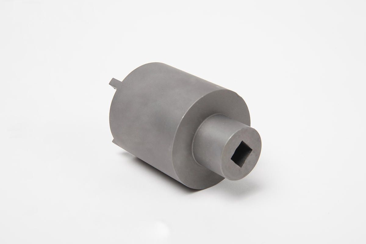
  • T-1451 Coupler Installation "Pacman" Tool
  • T-1069 Bearing-Nut Wrench Tool
  • T-1601 Collar-Nut Lock Tool

This procedure applies to the following service kits:

  • 93-24-7147: BALLSCREW, 32-6-1054.1
  • 93-24-9013: BALLSCREW, 32-6-993.6
  • 93-24-0010A: BSCREW 32-10-1054-.625"
  • 93-24-0019A: BSCREW 32-6-1210-.625" HW
  • 93-24-0020A: BSCREW 32-6-854-.625" HW
  • 93-24-0081A: BSCREW 32-10-1096-.625"
  • 93-24-0082A: BSCREW 32-10-1553-.625"
  • 93-24-0084A: BSCREW 32-20-1037-19
  • 93-24-0094: BSCREW 32-6-1271-.625"
  • 93-24-0103A: BSCREW 32-10-1633-.625"
  • 93-24-0106A: BSCREW 32-6-1464-.625" HW
  • 93-24-0131: BSCREW 32-10-1264.625”
  • 93-24-9012A: BSCREW 32-6-1367-.625"
  • 93-24-9013A: BSCREW 32-6-987-.625"
  • 93-24-9306A: BSCREW 32-6-1634-.625"
  • 93-24-9807A: BSCREW 32-6-1989-.625"
  • 93-4590: BSCREW 32-10-1977-.625"
  • 93-4591: BSCREW 32-20-1241-19

Removal- Ballscrew Motor

1

Jog the Y Axis away from the motor housing.

Push [POWER OFF].

Set the main circuit breaker to the OFF position.

Lock the main circuit breaker. Use an approved lock with an approved safety tag.

2

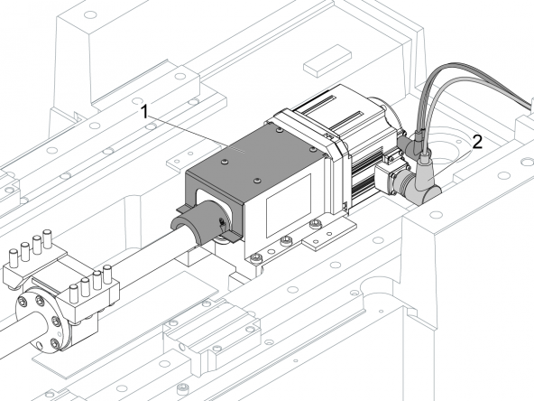
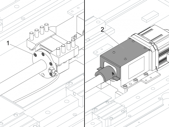
Remove the bracket-bumper assembly [1].

Note: The bracket-bumper assembly is different on some machines.

Disconnect the encoder and motor cables [2].

3

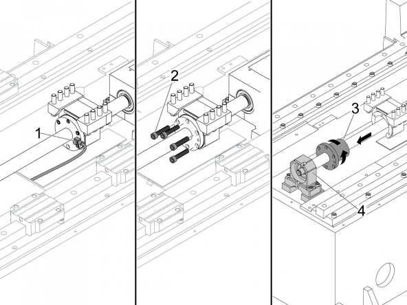
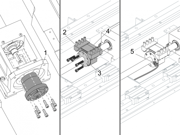
Record the position of the adapter [1] for the lubrication-fitting.

Remove the adapter for the lubrication-fitting.

Remove the (5) screws [2] from the ballnut.

Use your hand to turn the ballnut [3] counterclockwise.

Do this until the ballnut is 6" (15 cm) from the housing [4] for the support-bearing.

4

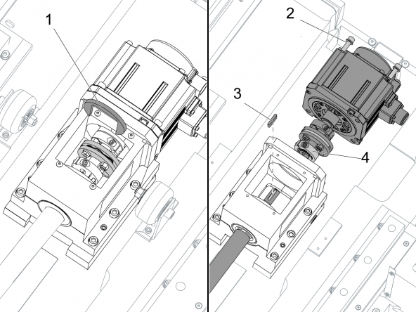
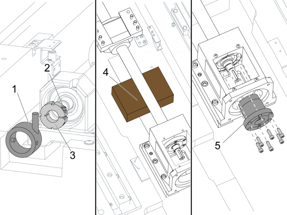
If necessary, remove the sheet-metal skirt and the air-lube panel to get access to the motor housing.

Install the coupler-installation tool [1] on the motor coupling.

Note: Turn the ballscrew so you can see the screw [4] for the motor-coupling clamp.

Remove the (4) motor screws [2].

Loosen the screw [4] on the motor-coupling clamp.

Remove the motor with the motor-coupling assembly.

Remove the ballscrew key [3].

Removal- Ballscrew

1

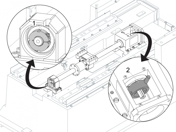
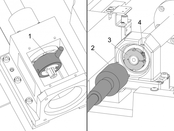
Loosen the locknut screw [1] on the support-bearing.

Note: If necessary, push the table to get access to the locknut screw.

Install the collar-nut lock tool [2] on the motor-housing locknut.

2

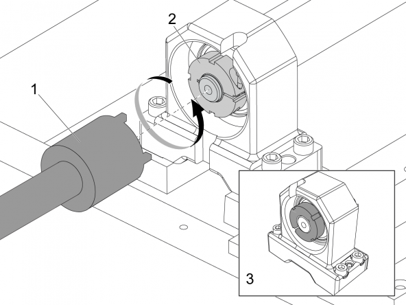
Use the bearing-nut wrench tool [1].

Turn the support-bearing locknut [2] counterclockwise, until it is flush [3] with the shaft of the ballscrew.

3

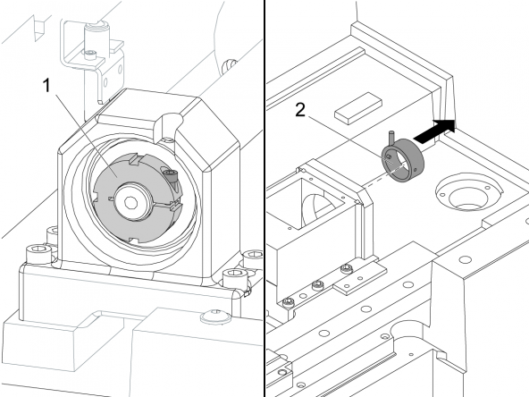
Tighten the support-bearing lock nut screw [1].

Remove the collar-nut lock tool [2] from the motor housing.

4

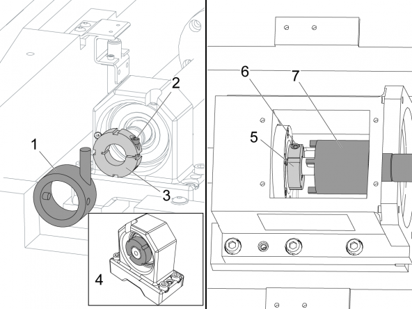
Loosen the screw [1] on the locknut for the motor-bearing.

Install the collar-nut lock tool [2] on the support-bearing housing.

 Note: Make sure the collar-nut wrench goes into the support-bearing housing slot and into the slots on the locknut.

Use the bearing-nut wrench tool [4] to loosen the locknut [3].

Remove the locknut.

5

Remove the collar-nut lock tool [1].

Loosen the locknut screw [2] and remove the support-bearing locknut [3].

Put a wood block [4] between the ballnut housing and the motor house. The wood block supports the ballscrew when the bearing pack is removed.

Remove the bearing pack [5] from the motor housing.

Note: If necessary, hold the bearing pack and turn the ballscrew counterclockwise to remove the bearing pack.

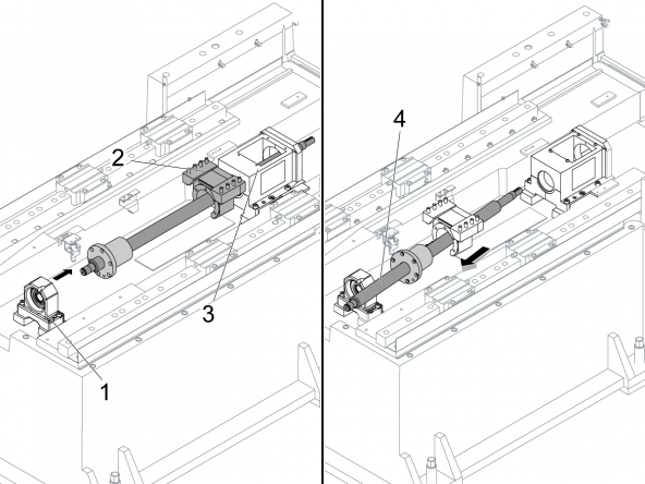
6

If you can easily remove the support bearing [1], it is a slip-fit bearing. Go to Step 7.

If you can not easily remove the support bearing, do not remove it. You cannot remove a press-fit bearing.

Push the housing [2] for the ballnut in the direction of the housing [3] for the motor.

Push the ballscrew in the direction of the housing for the motor.

Remove the ballscrew [4] diagonally.

7

If the support bearing [1] is a slip-fit bearing, remove it.

Pull the ballscrew through the support-bearing housing.

Remove the ballscrew [2] diagonally.

Installation- Ballscrew

Prerequisites

Make sure the size and pitch of the replacement ballscrew are the same as the removed ballscrew.

The ballscrew may need spacers. Refer to Ballscrew Spacer-Installation.

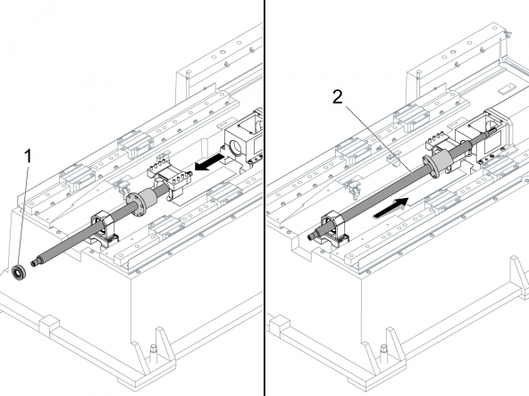
1

If the support bearing is press-fit, go to step 2.

If the support bearing is slip-fit, turn the ballnut [1] until it is near the center of the ballscrew [2].

Install the ballscrew diagonally .

Push the ballscrew through the support-bearing housing [3].

Put the wave washer [5] onto the ballscrew shaft.

Install the slip-fit support bearing [4] onto the ballscrew shaft.

Push the ballscrew through the nut housing [6] and into the housing [7] for the motor.

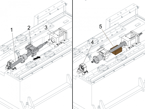
2

If the support bearing is press-fit bearing, install the ballscrew [1] diagonally.

Push the ballscrew through the ballnut housing [2] and into the motor housing [3].

Pull the ballscrew into the press-fit bearing [4].

Put a wood block [5] near the motor housing. This helps support the ballscrew.

3

Clean the ballnut flange and mating face of the nut housing fully.

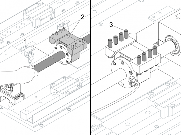
Install the motor-housing bearing pack [1].

Torque the screws for the bearing pack. Refer to Haas Fastener Torque Specifications. Use the values for steel.

Turn the ballnut [2] until the lubrication-fitting port [3] is very near to the position you recorded during removal.

Push the table until the ballnut goes into the ballnut housing [4].

Turn the ballnut slightly to align the screw holes. Attach the ballnut to the ballnut housing.

Use your fingers to tighten the screws.

Install the lube-fitting adapter [5].

Use your hand to to tighten the lubrication-fitting adapter [2].

Remove the wood block.

4

Install the locknut [3] for the support bearing.

Make sure the locknut is flush with the ballscrew [4].

Tighten the clamp screw [2] for the locknut.

Attach the lock tool [1] for the collar nut.

Install the locknut [5] for the motor bearing.

Use the wrench tool [7] for the bearing nut to torque the locknut [5] to 15 ft-lb (20 Nm).

Torque the screw [6] on the locknut. Refer to Ballscrew - Installation Tools and Torque Specifications.

Remove the lock tool [1] for the collar-nut from the support-bearing casting.

Loosen the clamp screw [2] on the locknut for the bearing support.

5

Install the lock tool [1] for the collar nut onto the locknut for the motor bearing.

Use the wrench [2] for the bearing nut to torque the locknut [3] for the support bearing to 4 in-lb (0.5 Nm).

Remove the collar-nut lock tool [1] from the motor-bearing housing.

Torque the screw [4] on the locknut. Refer to Ballscrew - Installation Tools and Torque Specifications.

Install the bracket-bumper assembly on the housing for the support bearing.

Go to Top


Installation- Ballscrew Motor

1

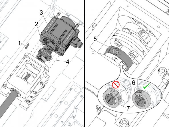
Apply a thin layer of grease to the ballscrew key [1].

Install the ballscrew key.

Make sure the coupler-installation tool [2] is installed.

Install the motor [3] with the motor-coupling assembly [4] on the ballscrew shaft.

Torque the (4) motor screws. Refer to Haas Fastener Torque Specifications. Use the values for iron.

Remove the coupler-installation tool [2] from the motor coupling.

Make sure the slot in the motor-coupler [6] is not aligned with the slot [7] in the motor shaft.

Torque the screw [5] for the motor-coupling clamp. Refer to Ballscrew - Installation Tools and Torque Specifications.

Install the encoder cable [3] and the motor cable [3].

2

Push POWER ON.

Set Setting 53, Jog w/o Zero Return, to ON.

Jog the Y Axis in the positive (+) direction to the end of travel.

 Caution: Do not run the ballnut into the hard stop.

Push  [EMERGENCY STOP]

Torque the screws [1] that hold the ballnut. Refer to Haas Fastener Torque Specifications. Use the values for iron.

Release the  [EMERGENCY STOP]. Push [RESET] to stop the alarms.

Jog the Y Axis in the negative (-) direction to the end of travel.

Push  [EMERGENCY STOP]

Install the bracket-bumper assembly [2].

3

Use your hand to turn the ballscrew [1] in one direction. Turn the ballscrew until the table is at the end of travel.

Turn the ballscrew [1] the other direction until the table is at the end of travel.

If the ballscrew is correctly aligned to the ballnut housing [2], the ballscrew turns with constant tension.

If the tension changes while you turn the ballscrew, you must adjust the ballnut housing.

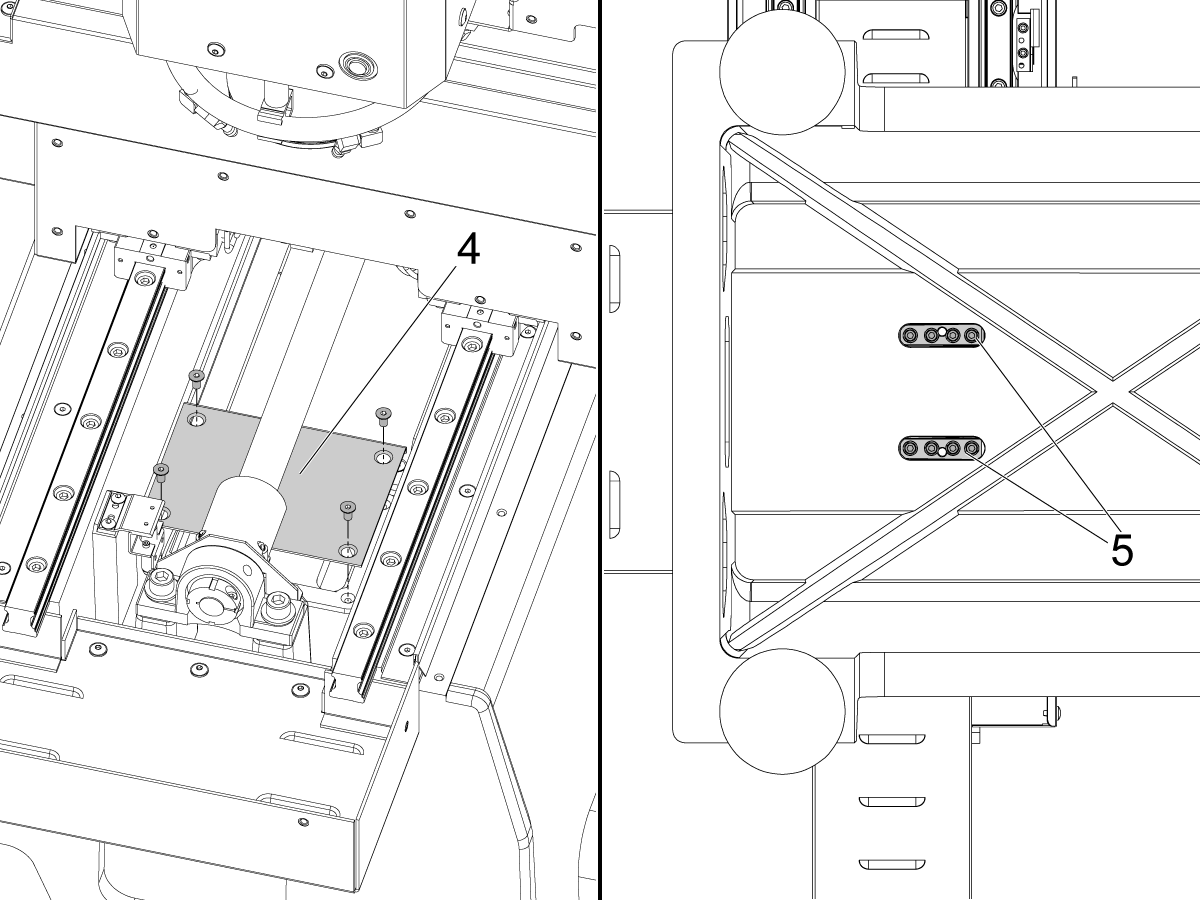
To adjust the ballnut housing, do these steps:

  • Loosen the (8) screws [3] that hold the ballnut housing to the saddle assembly. For Minimill reboot machines, these screws are difficult to access. Remove the cover [4] and turn the ball screw so that the ballnut housing screws are accessible from underneath the base [5] as shown.
  • Release the  [EMERGENCY STOP]. Push [RESET] to stop the alarms.

  • Jog the table in the negative (-) to the end of travel.

  • Jog the table in the positive (+) to the end of travel.

  • Push [EMERGENCY STOP].

  • Turn the ballscrew with your hand to make sure the table moves with constant tension. If the tension is not constant, go to step 4.
  • If the tension is constant, incrementally torque the (8) screws that hold the ballnut housing to the saddle assembly in a star pattern. Refer to Haas Fastener Torque Specifications. Use the values for iron.

4

Again turn the ballscrew in each direction to the end of travel.

If the tension continues to change while you turn the ballscrew, do these steps:

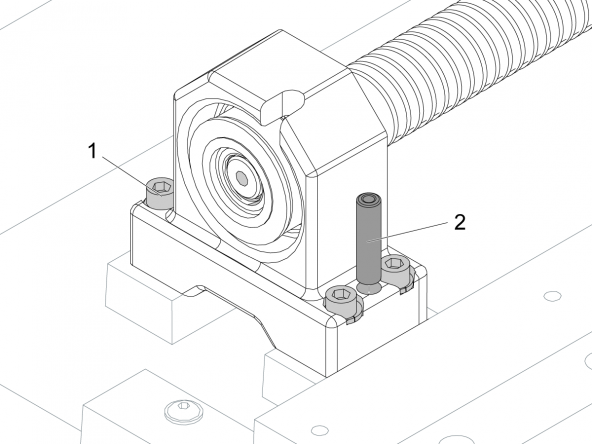
Loosen the (4) screws [1] on the bearing support. Keep the screws sufficiently tight to control the adjustment.

Remove and discard the alignment pins [2].

Note: Alignment pins are used only in production to decrease assembly time. They do not keep the ballscrew aligned.

When the table moves with constant tension, torque the (4) screws in a star pattern. Refer to Haas Fastener Torque Specifications. Use the value for iron.

Do Step 3 again.

Set Setting 53 to OFF.

5

Proceed to the following procedures:
  • Do the VMC - Axis Grid Offset procedure.
  • Do the VMC - Axis Ballscrew - Backlash Test procedure.
  • Do the Ballbar Anaylisis - Quick Check Mode procedure.
  • See the Renishaw Ballbar Test - Plot Interpretation - Mills document.

Recently Viewed Items

You Have No Recently Viewed Items Yet

Feedback
Haas Logo

Haas Delivered Price

This price includes shipping cost, export and import duties, insurance, and any other expenses incurred during shipping to a location in France agreed with you as a buyer. No other mandatory costs can be added to the delivery of a Haas CNC Product.

KEEP UP WITH THE LATEST HAAS TIPS AND TECHNOLOGY...

Sign up now!   

HAAS TOOLING ACCEPTS THE FOLLOWING:

  • Service & Support
  • Owners
  • Request Service
  • Operator Manuals
  • Haas Parts
  • Rotary Repair Request
  • Pre-Install Guides
  • Shopping Tools
  • Build & Price a New Haas
  • Available Inventory
  • The Haas Price List
  • CNCA Financing
  • About Haas
  • Accessibility Statement
  • DNSH Statement
  • Export Compliance
  • Careers
  • Certifications & Safety
  • Contact Us
  • History
  • Terms & Conditions
  • Haas Tooling Terms & Conditions
  • Privacy
  • Warranty
  • Haas Community
  • Haas Certification Program
  • Haas Motorsports
  • Gene Haas Foundation
  • Haas Technical Education Community
  • Events
  • Join the Conversation
  • Facebook
  • X
  • Flickr
  • YouTube
  • LinkedIn
  • Instagram
  • TikTok
© 2026 Haas Automation, Inc – CNC Machine Tools
This site is protected by reCAPTCHA and the Google Privacy Policy and Terms of Service apply.

2800 Sturgis Rd., Oxnard, CA 93030
Toll Free: (888) 817-4446 / Fax: 805-278-8554