My Haas Welcome,
!
Haas Tooling MyHaas/HaasConnect Sign In Register Haas Tooling MyHaas/HaasConnect Sign Out Welcome, My Machines Latest Activity My Quotes My Account My Users Sign Out
Find Your Distributor
  1. Select Language
    1. English
    2. Deutsch
    3. Español - ES
    4. Español - MX
    5. Français
    6. Italiano
    7. Português
    8. Český
    9. Dansk
    10. Nederlands
    11. Magyar
    12. Polski
    13. Svenska
    14. Türkçe
    15. 中文
    16. Suomi
    17. Norsk
    18. الإنجليزية
    19. български
    20. Hrvatski
    21. Ελληνικά
    22. Română
    23. Slovenský
    24. Slovenščina
    25. 한국어
    26. 日本語
    27. Українська
  • machines Main Menu
    • Vertical Mills
      Vertical Mills
      Vertical Mills View All
      • Vertical Mills
      • VF Series
      • Universal Machines
      • VR Series
      • VP-5 Prismatic
      • Pallet-Changing VMCs
      • Mini Mills
      • Mold Machines
      • High-Speed Drill Centers
      • Drill/Tap/ Mill Series
      • Toolroom Mills
      • Pocket Mill
      • Compact Mills
      • Gantry Series
      • SR Sheet Routers
      • Extra-Large VMC
      • Double-Column Mills
      • 3+2 Positioning Machines
    • Multi-Axis Solutions
      Multi-Axis Solutions
      Multi-Axis Solutions View All
      • Multi-Axis Solutions
      • Y-Axis Lathes
      • 5-Axis Mills
    • Lathes
      Lathes
      Lathes View All
      • Lathes
      • ST Series
      • Dual-Spindle
      • Box Way Series
      • Toolroom Lathes
      • Chucker Lathe
      • Pocket Lathe
      • Haas Bar Feeders
    • Horizontal Mills
      Horizontal Mills
      Horizontal Mills View All
      • Horizontal Mills
      • 50-Taper
      • 40-Taper
    • Rotaries & Indexers
      Rotaries & Indexers
      Rotaries & Indexers View All
      • Rotaries & Indexers
      • Rotary Tables
      • Indexers
      • 5-Axis Rotaries
      • Extra-Large Rotaries
    • Special Series
      Special Series
      Special Series View All
      • Special Series
      • EU_Series_Redirect
    • Automation Systems
      Automation Systems
      Automation Systems View All
      • Automation Systems
      • Mill Automation
      • Lathe Automation
      • Automatic Parts Loaders
      • Automation Models
    • Desktop Machines
      Desktop Machines
      Desktop Machines View All
      • Desktop Machines
      • Desktop Mill
      • Desktop Lathe
      • Control Simulator, Standard
      • Control Simulator, Premium
    • Shop Equipment
      Shop Equipment
      Shop Equipment View All
      • Shop Equipment
      • Knee Mill
      • Haas Manual Lathes
      • Haas Saws
    • Fabrication Machines
      Fabrication Machines
      Fabrication Machines View All
      • Fabrication Machines
      • Laser Cutting Machines
      • CNC Press Brakes
    • QUICK LINKS Special Series  Special Series 
      EU SERIES EU SERIES BUILD & PRICE | PRICE LIST BUILD & PRICE | PRICE LIST In-Stock Machines In-Stock Machines WHAT’S NEW WHAT’S NEW YOUR FIRST CNC YOUR FIRST CNC
      SHOPPING TOOLS
      • Build & Price a Haas
      • Price List
      • Available Inventory
      • CNCA Financing
      WANT TO TALK TO SOMEONE?

      A Haas Factory Outlet (HFO) can answer your questions, and walk you through your best options.

      CONTACT YOUR DISTRIBUTOR >
  • Options Main Menu
    • The Haas Control Value Option Packages
      Value Option Packages
      Value Option Packages View All
      • Value Option Packages
    • Product Image Spindles
      Spindles
      Spindles View All
      • Spindles
    • Product Image Tool Changers
      Tool Changers
      Tool Changers View All
      • Tool Changers
    • Product Image 4th- | 5th-Axis
      4th- | 5th-Axis
      4th- | 5th-Axis View All
      • 4th- | 5th-Axis
    • Product Image Turrets & Live Tooling
      Turrets & Live Tooling
      Turrets & Live Tooling View All
      • Turrets & Live Tooling
    • Product Image Probing
      Probing
      Probing View All
      • Probing
    • Haas Chip & Coolant Management Chip & Coolant Management
      Chip & Coolant Management
      Chip & Coolant Management View All
      • Chip & Coolant Management
    • The Haas Control The Haas Control
      The Haas Control
      The Haas Control View All
      • The Haas Control
    • Product Image Product Options
      Product Options
      Product Options View All
      • Product Options
    • Product Image Tooling & Fixturing
      Tooling & Fixturing
      Tooling & Fixturing View All
      • Tooling & Fixturing
    • Product Image Workholding
      Workholding
      Workholding View All
      • Workholding
    • Product Image 5-Axis Solutions
      5-Axis Solutions
      5-Axis Solutions View All
      • 5-Axis Solutions
      • 5 Easy Steps to 5-Axis
    • QUICK LINKS Special Series  Special Series 
      EU SERIES EU SERIES BUILD & PRICE | PRICE LIST BUILD & PRICE | PRICE LIST In-Stock Machines In-Stock Machines WHAT’S NEW WHAT’S NEW YOUR FIRST CNC YOUR FIRST CNC
      SHOPPING TOOLS
      • Build & Price a Haas
      • Price List
      • Available Inventory
      • CNCA Financing
      WANT TO TALK TO SOMEONE?

      A Haas Factory Outlet (HFO) can answer your questions, and walk you through your best options.

      CONTACT YOUR DISTRIBUTOR >
  • Why Haas Main Menu
      Discover the Haas Difference
    • Why Haas
    • MyHaas
    • Education Community
    • Industry 4.0
    • Haas Certification
    • Customer Testimonials
  • Service Main Menu
      Welcome to Haas Service
      SERVICE HOME Operator’s Manuals How-To Procedures Troubleshooting Guides Preventive Maintenance Haas Parts Haas Tooling Videos
  • Videos Main Menu
  • Main Menu
    • View All
    • View All
    • View All
    • View All
      • HTEC Curriculum Support
      • Haas Value Option Packages (VOP) Journey
    • View All
      • Haas 10 kg Cobot Package
      • Cobot Kits
      • DC-1 Drill Center
      • CNC Sales News
      • Do More With Your Haas
    • View All
    • View All
      • contact-us-test
      • 4 - AUTOMATION SYSTEMS
      • Carousel-V2
      • expert test
      • Demo_Day_Trident-test
      • Link Test
      • image-sale-tag-test
      • article-list-test
      • Haas 25 kg Robot Package
      • test-algolia-page
    • View All
    • View All
    • View All
    • View All
      • calc-test
    • View All
    • QUICK LINKS Special Series  Special Series 
      EU SERIES EU SERIES BUILD & PRICE | PRICE LIST BUILD & PRICE | PRICE LIST In-Stock Machines In-Stock Machines WHAT’S NEW WHAT’S NEW YOUR FIRST CNC YOUR FIRST CNC
      SHOPPING TOOLS
      • Build & Price a Haas
      • Price List
      • Available Inventory
      • CNCA Financing
      WANT TO TALK TO SOMEONE?

      A Haas Factory Outlet (HFO) can answer your questions, and walk you through your best options.

      CONTACT YOUR DISTRIBUTOR >
  • Haas Tooling Main Menu
  • Haas Service Parts Main Menu

My Haas Welcome,
!
Haas Tooling MyHaas/HaasConnect Sign In Register Haas Tooling MyHaas/HaasConnect Sign Out Welcome, My Machines Latest Activity My Quotes My Account My Users Sign Out
Find Your Distributor
  1. Select Language
    1. English
    2. Deutsch
    3. Español - ES
    4. Español - MX
    5. Français
    6. Italiano
    7. Português
    8. Český
    9. Dansk
    10. Nederlands
    11. Magyar
    12. Polski
    13. Svenska
    14. Türkçe
    15. 中文
    16. Suomi
    17. Norsk
    18. الإنجليزية
    19. български
    20. Hrvatski
    21. Ελληνικά
    22. Română
    23. Slovenský
    24. Slovenščina
    25. 한국어
    26. 日本語
    27. Українська
×

Search Results

Web Pages

Images

    • <
    • 1
    • >

VR-11 Head Assembly Removal and Replacement - AD0046

Service Home How To Procedures VR-11 Head Assembly Removal and Replacement - AD0046
Recently Updated Last updated: 08/08/2023

Head Assembly Removal and Replacement - VR-11


AD0046

Applies to machines built from: July, 2013

VR-11 Head Assembly Removal and Replacement - AD0046

- Jump to Section - 1. Introduction 2. Spindle Removal (13 steps) 3. Internal Sheet Metal Removal (11 steps) 4. Internal Sheet Metal Removal (13 steps) 5. Head Assembly Installation (10 steps) 6. Spindle Installation (19 steps) Back to Top

Introduction

This procedure tells you how to remove and replace the head assembly on a VR-11 mill. You must mechanically lift the spindle motor and head assembly out of the mill. Remove all sheet metal pieces to make it easy to access these assemblies.

Make sure you have shop air connected to the A and B Axis when you do this procedure.

Spindle Removal

1

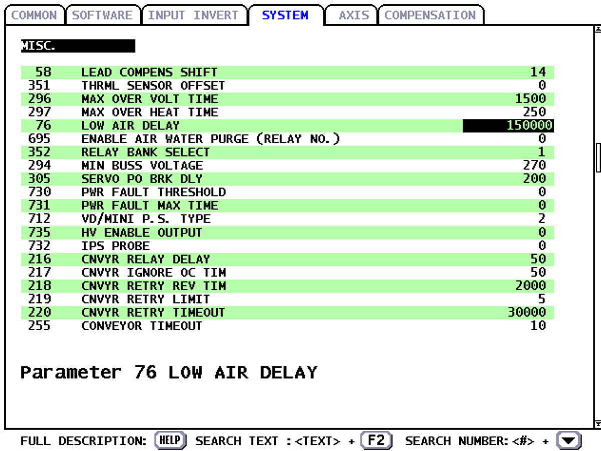
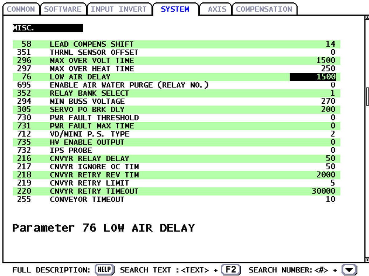
Set Parameter 76 Low Air Delay to a high number so that the machine will not alarm out.

2

Press [EMERGENCY STOP].

Disconnect the air supply from the air/lube panel.

3

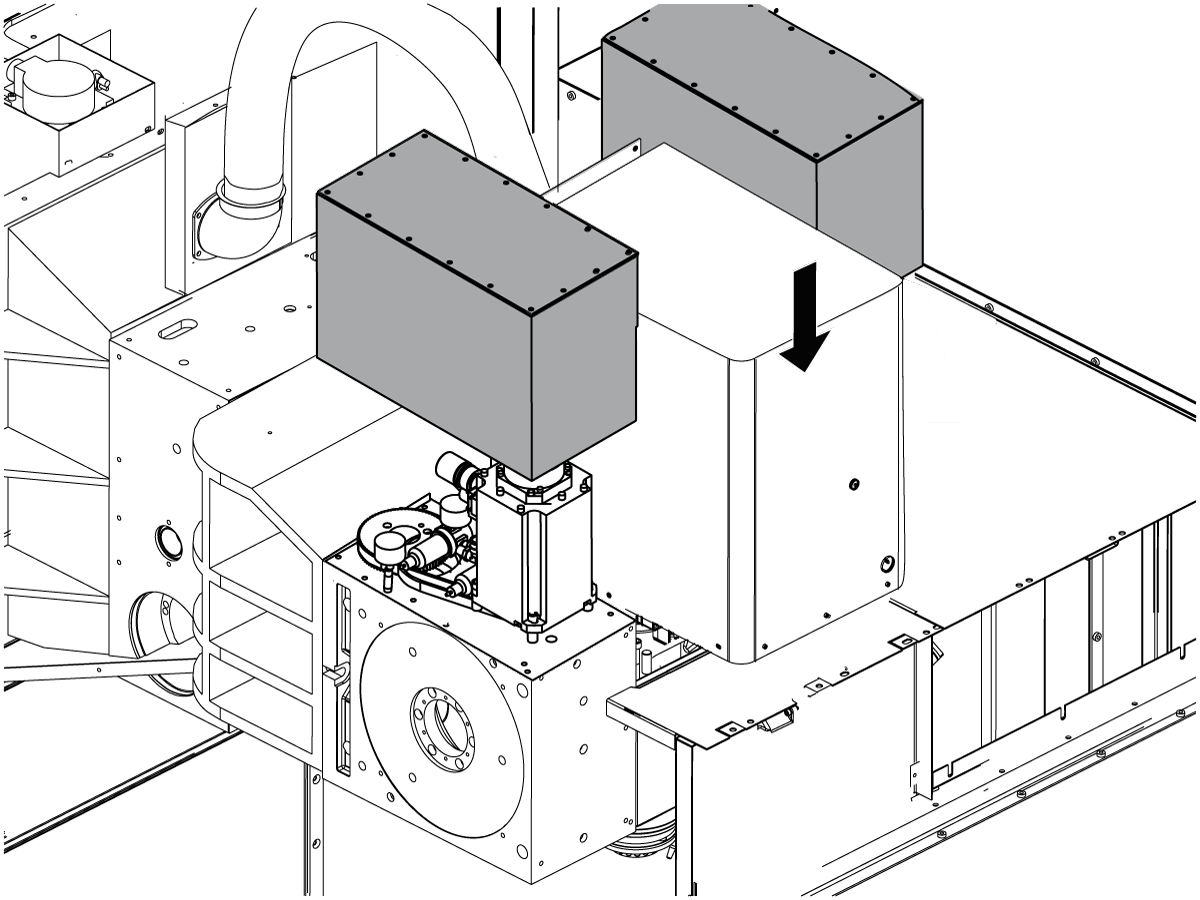
Rotate the A Axis to gain access to the screws that secure the spindle head cover. Remove the screws and the cover. Once the cover is removed, rotate the A Axis back to its home position.

4

Disconnect the air hose and tool clamp switches from the spindle connection plate.

5

Remove the TRP assembly.

6

Disconnect the spindle lubrication hose from the spindle. Remove the 90 degree connection from the spindle.

7

Loosen the spindle motor so that the spindle belt is loose on the spindle.

8

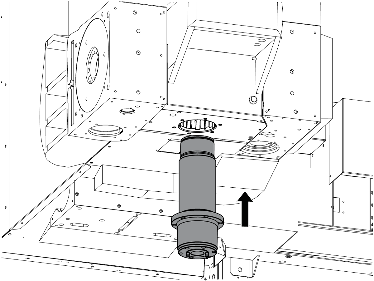
Remove the spindle from the spindle head casting.

9

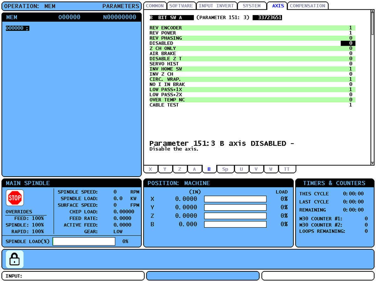
Press [SETNG/GRAPH].

Change Setting 7 Parameter Lock to OFF.

Press [PARAM/DGNOS].

Set Paramater 278:14 to 0.

Set Parameter 151:3 to 0.

Set Parameter 43:3 to 0.

10

Power off and lockout/tagout machine.

11

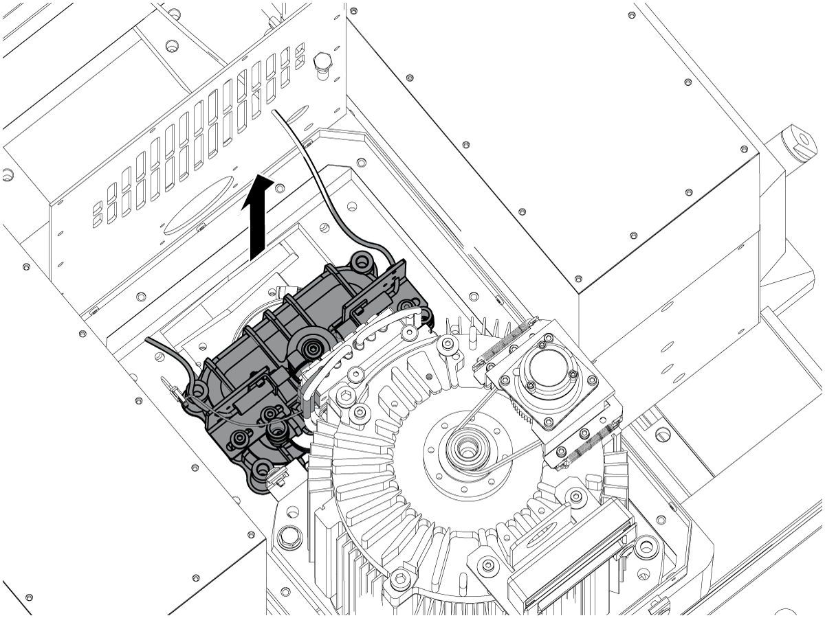
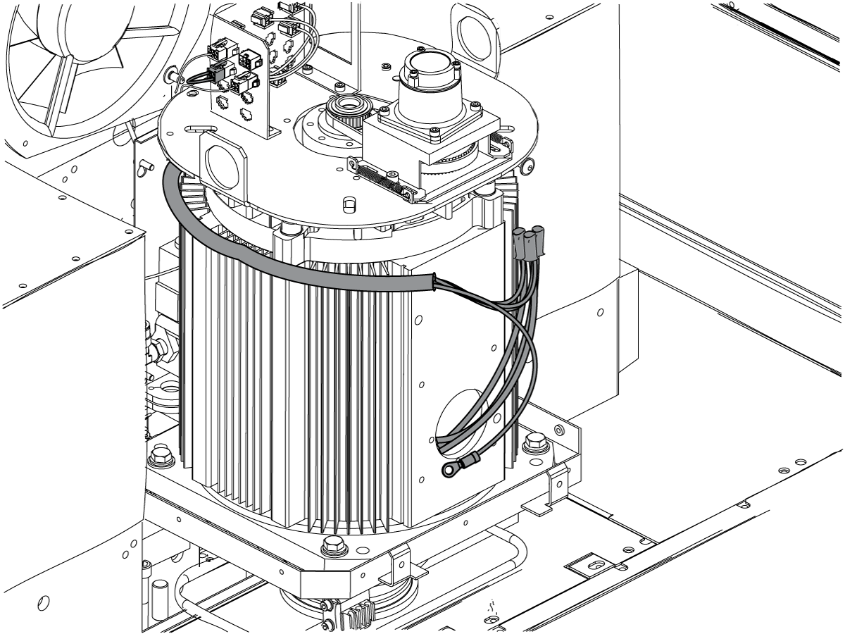
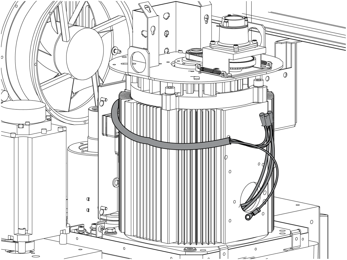
Disconnect all of the electrical connections from the spindle motor. Cap off the spindle motor leads. Leave the spindle encoder connected to provide a reference signal.

12

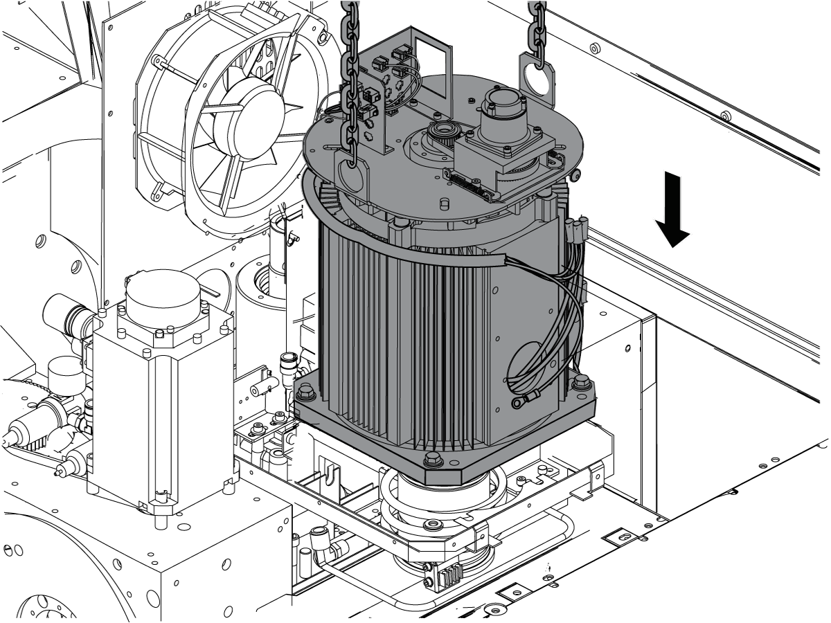
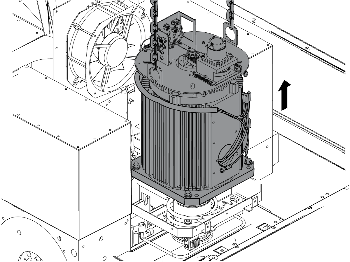
Remove the spindle motor.

 Caution: The spindle motor weighs at least 112 lb (55 kg). Make sure to use a lift that is rated for the weight of the spindle motor assembly

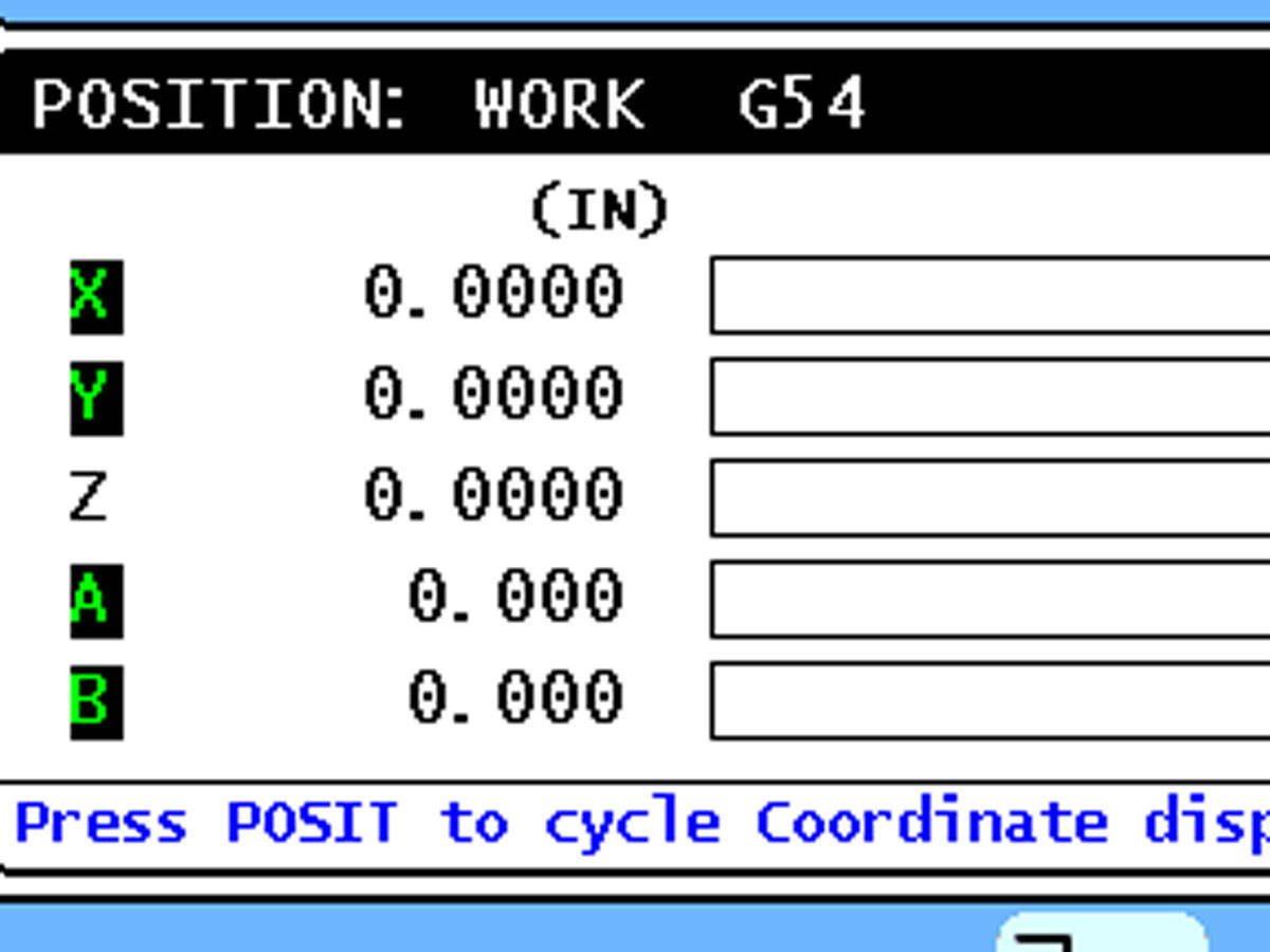
13

Zero return the X, Y, and Z Axes.

 Caution: Do not zero return ALL axes or you will damage the head assembly. Return the axes individually.

Internal Sheet Metal Removal

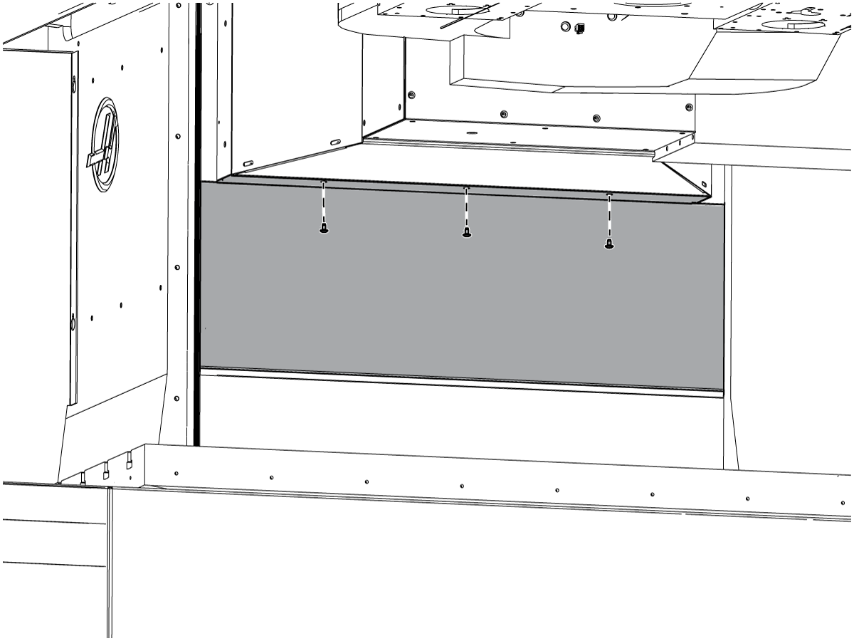
1

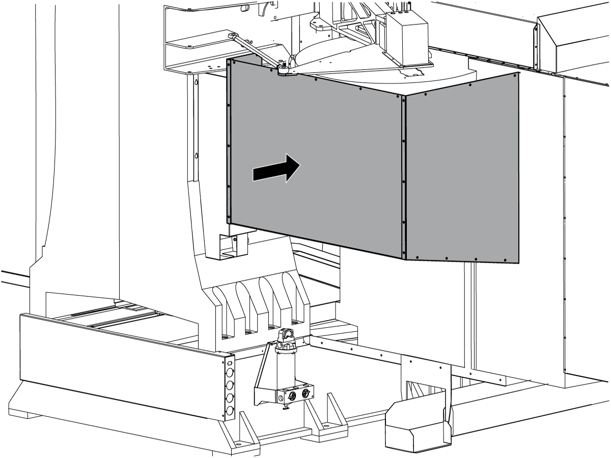
Remove the (3) screws that attach the Z Axis way cover to the head.
Lower the Z Axis way cover.

2

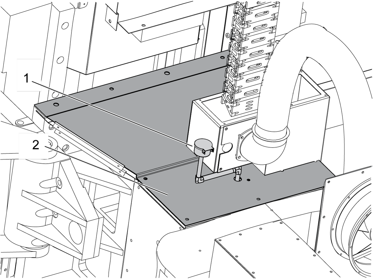
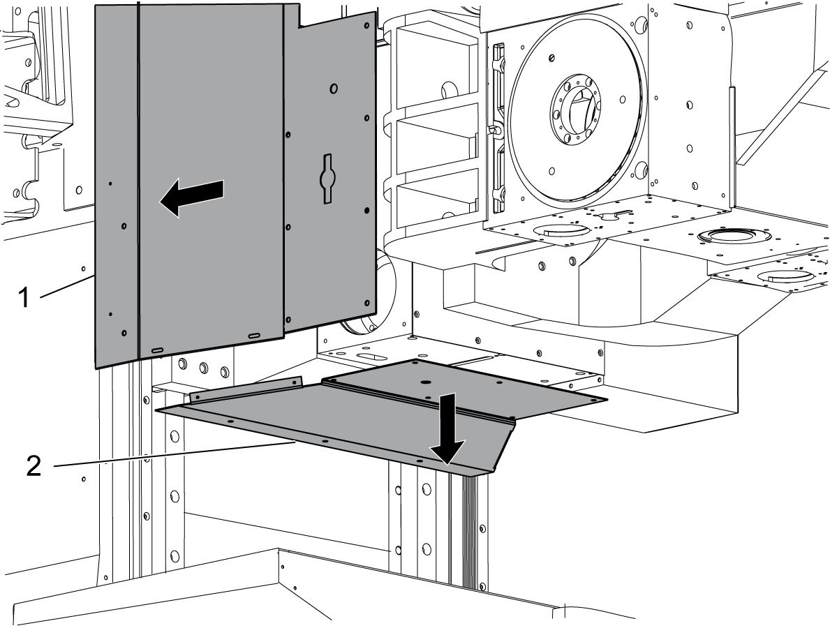
Remove the right side spacer cover [1] and the 450 lower cover [2].

3

Remove the left side spacer cover.

4

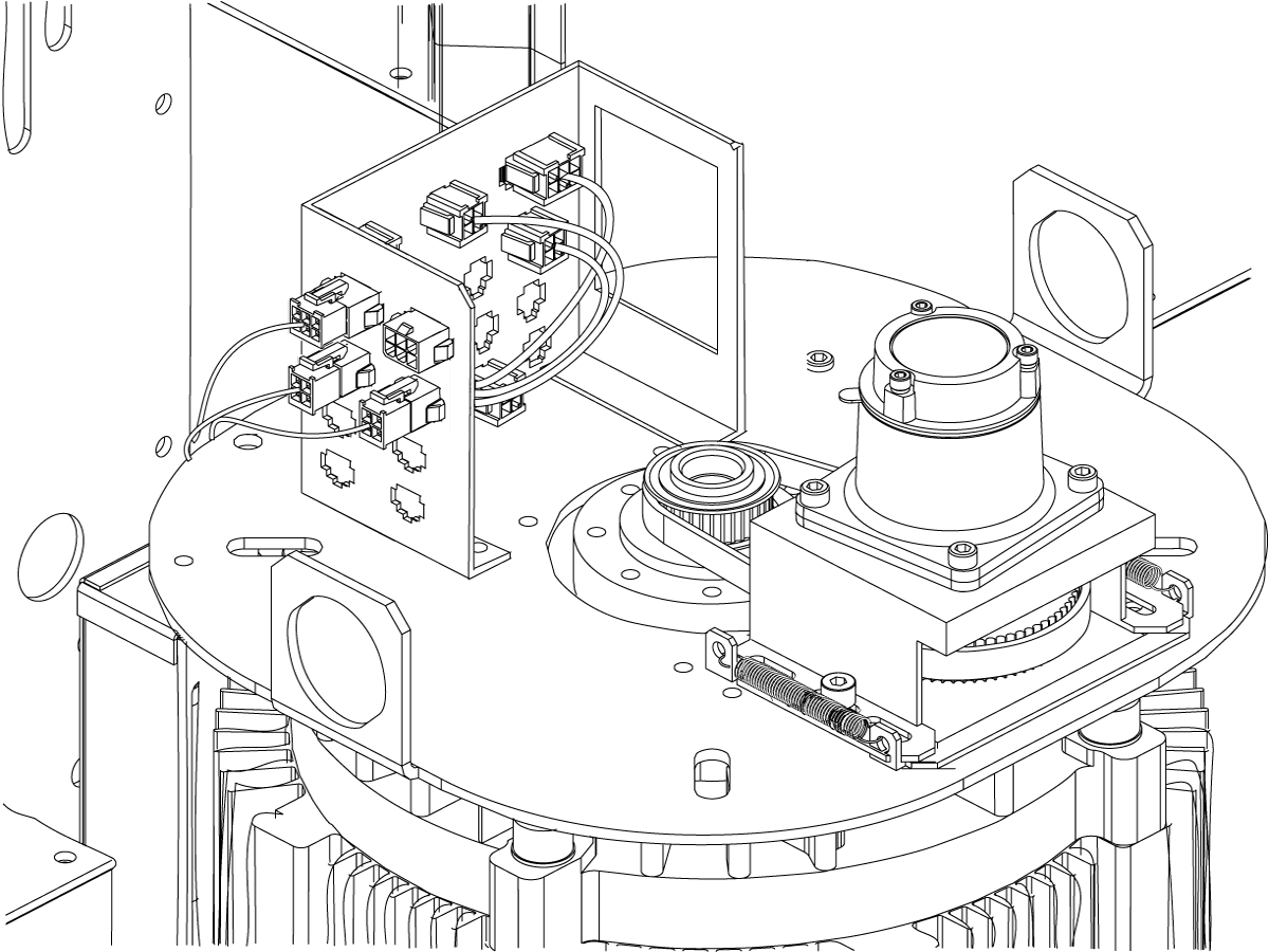
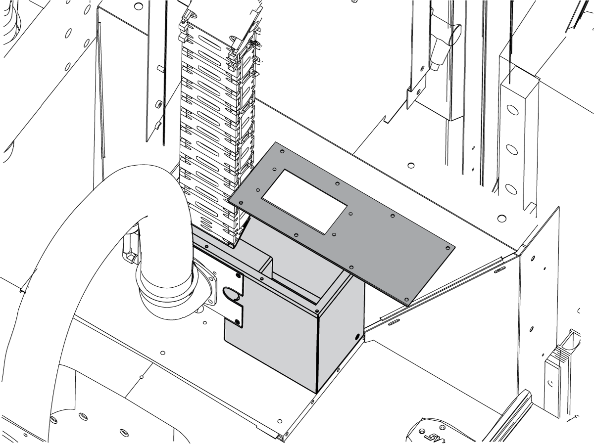
Remove the cover of the junction box on the top of the 450 rotary (B Axis).
Remove the screws inside the junction box that hold it to the upper sheet metal panel.
Do not remove the junction box.

5

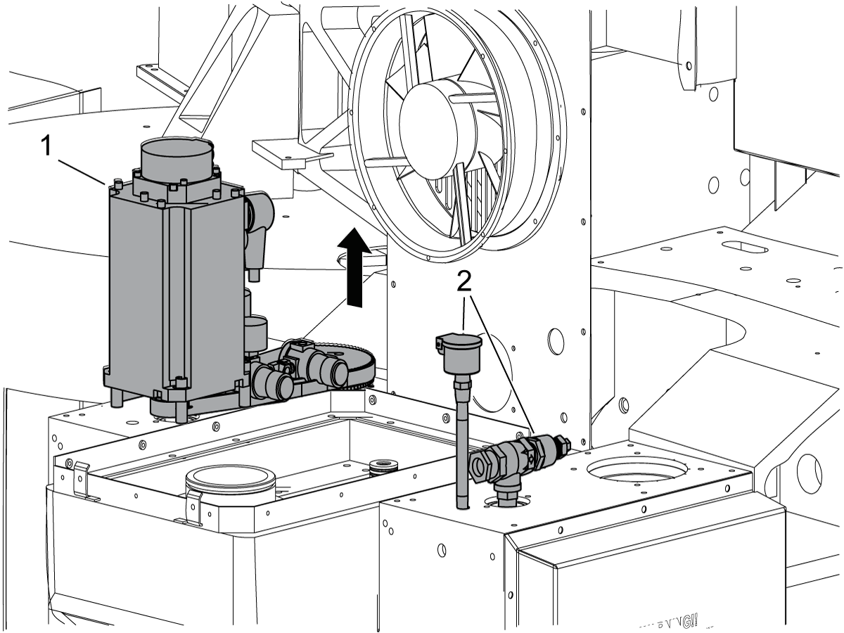
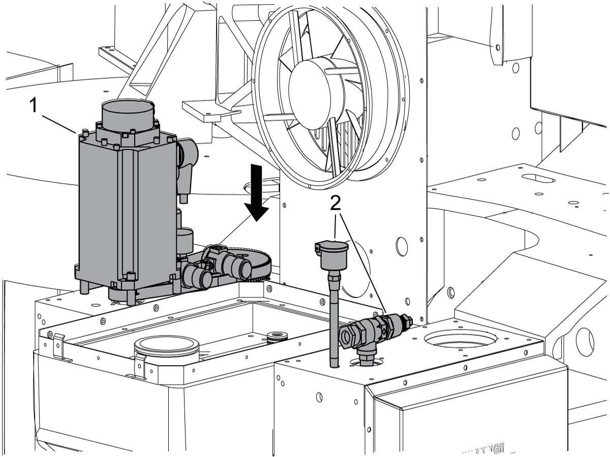
Remove the fill tube [1] and the upper sheet metal panel [2] from the top of the 450 rotary.

6

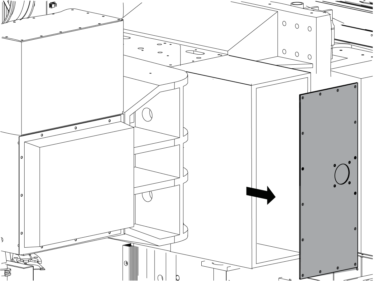
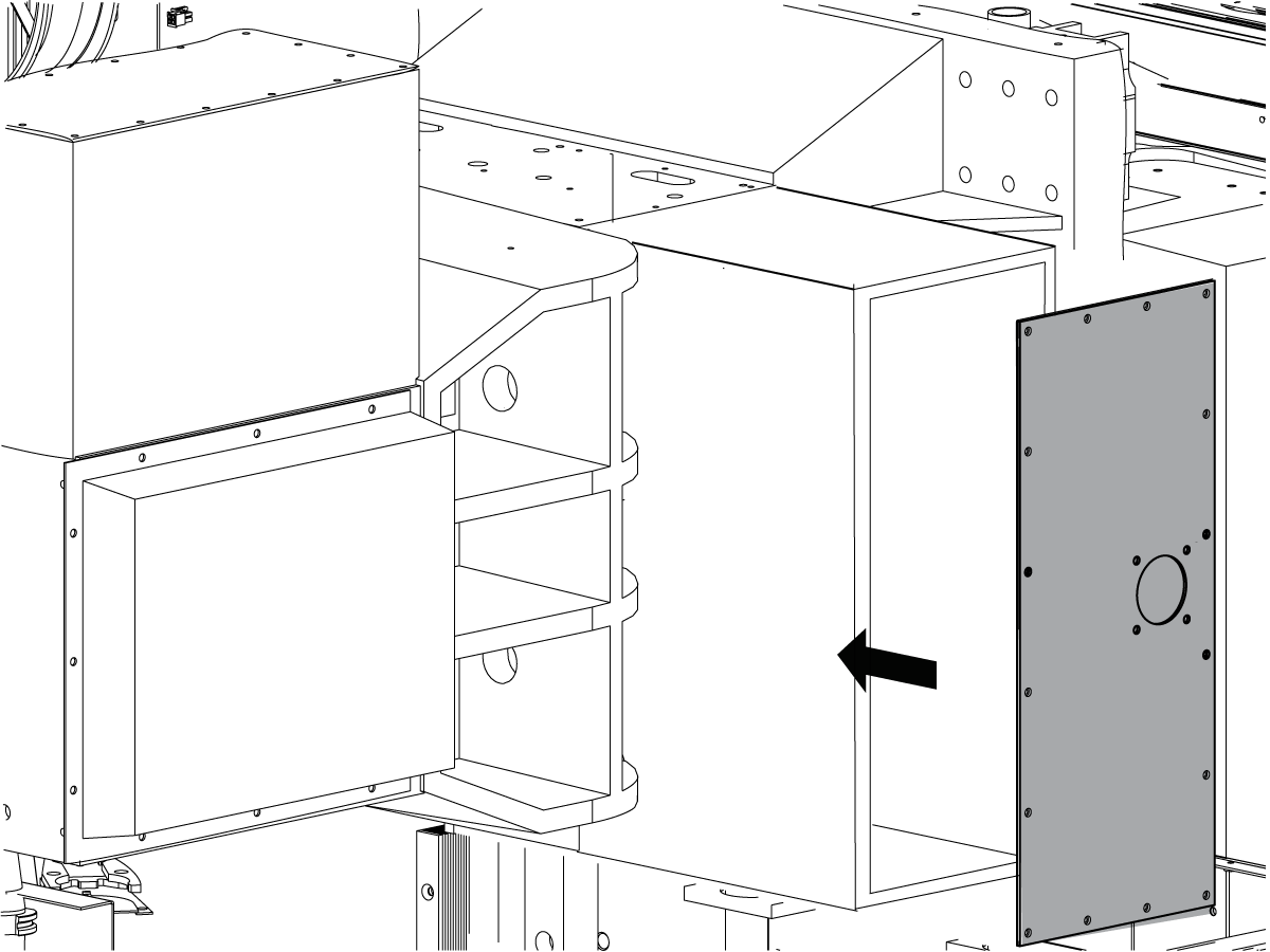
Remove the motor cover plate from the 450 rotary.

7

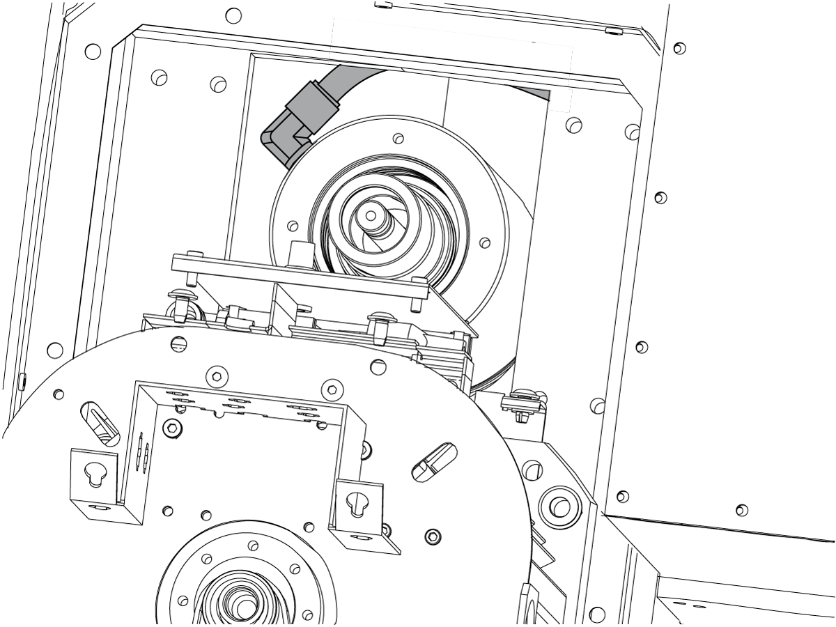
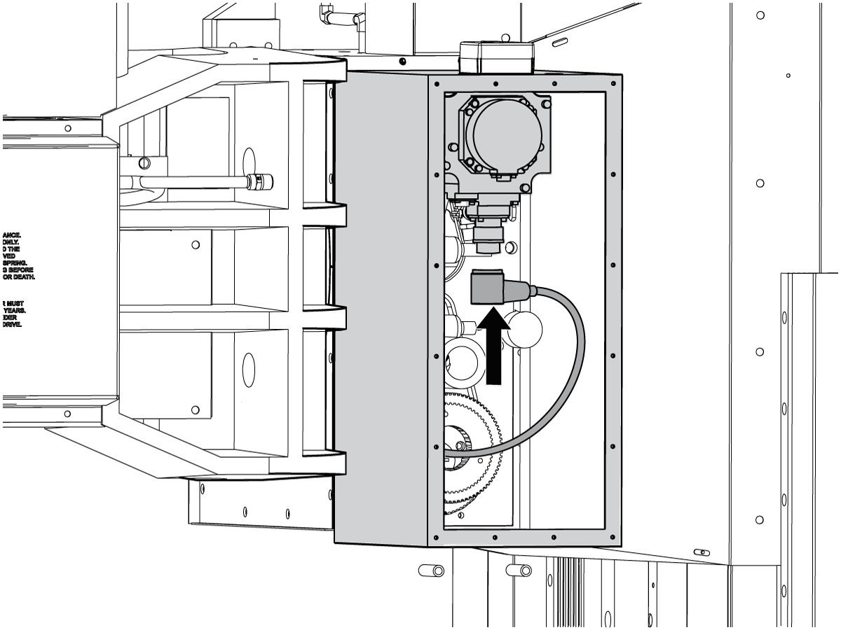
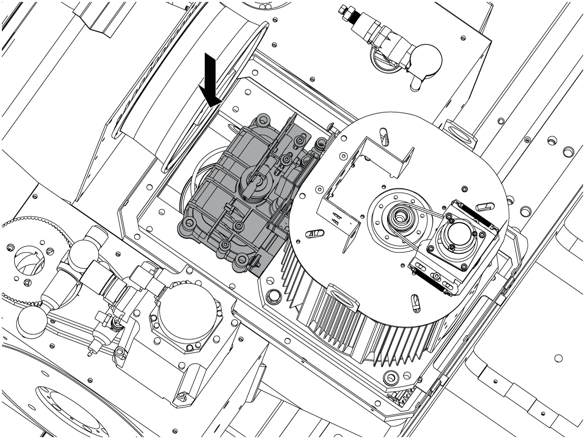
Disconnect the motor lead and the brake hose from the 450 rotary drive.
Feed the motor lead and the brake hose through the holes in the 450 motor cover and remove the cover.

8

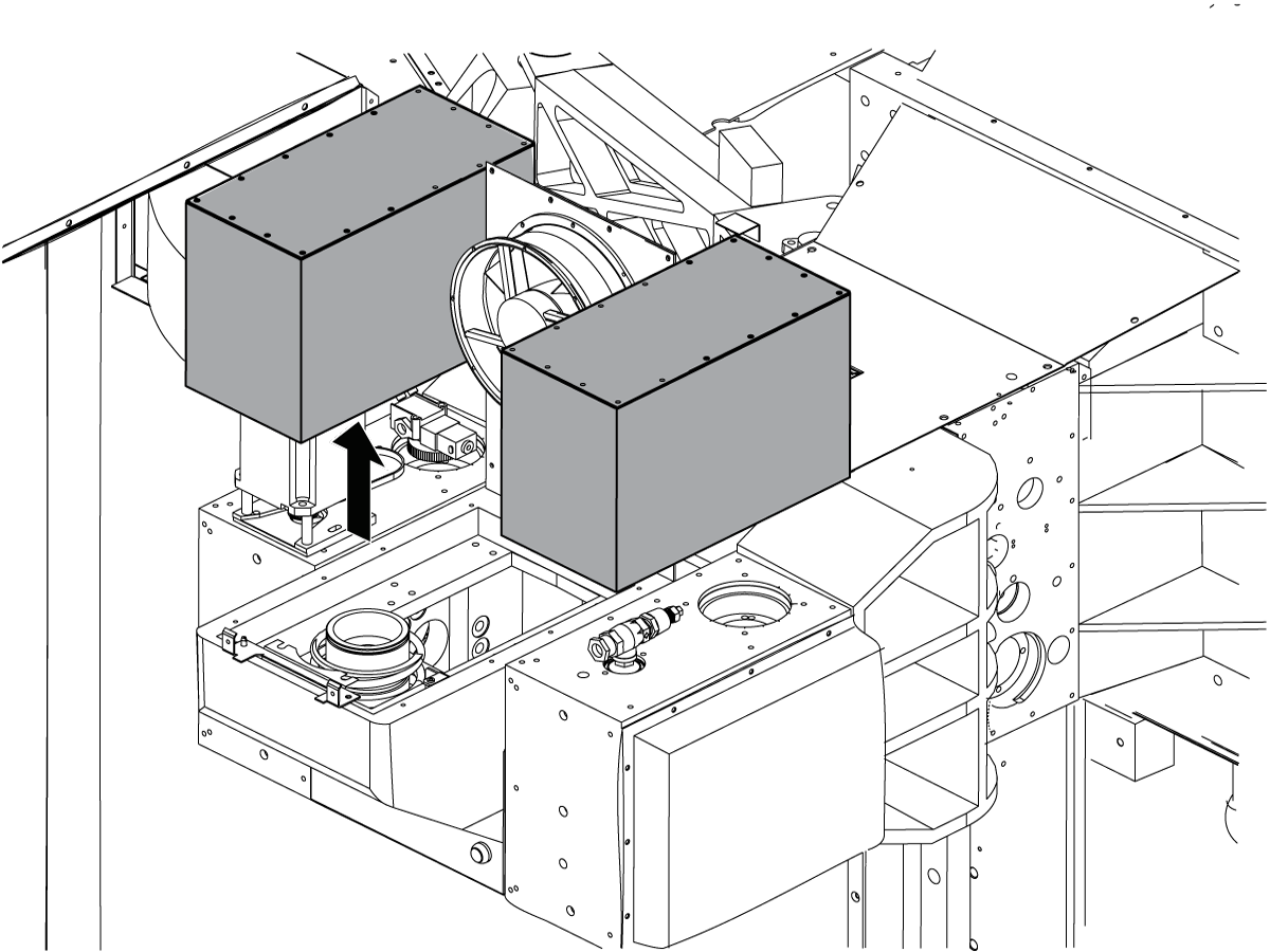
Remove the sheet metal housing from each of HRT310 rotaries (A Axis).
Remove the A Axis cable and brake air hoses.

9

Remove the A Axis motor and pulley [1] from the left 310 rotary.
Remove the fittings [2] from the right 310 rotary.

10

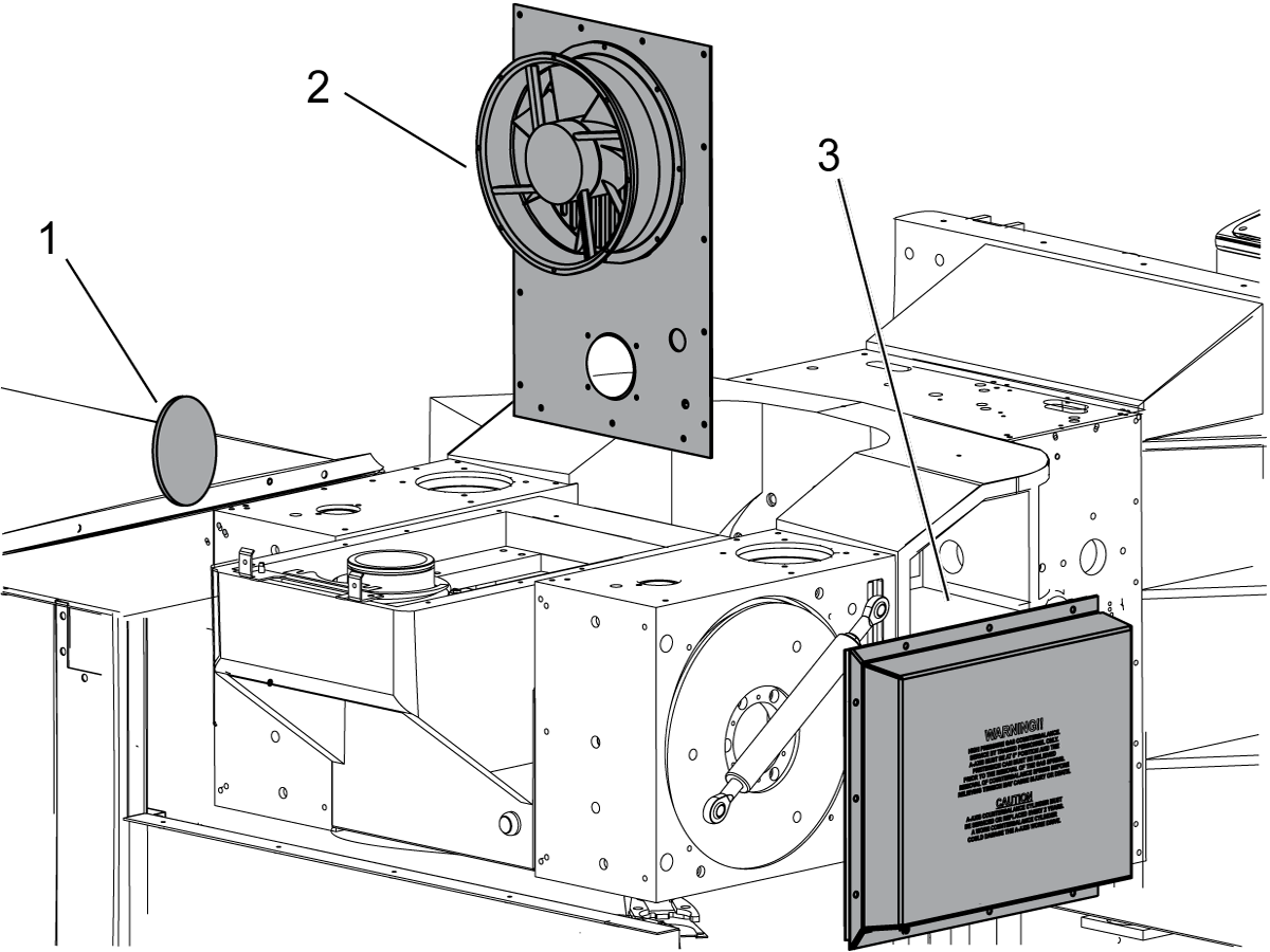
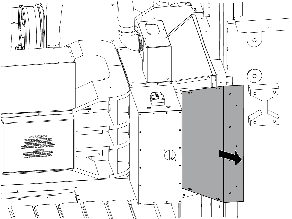
Remove the bore plate [1] from the left 310 rotary.
Remove the fan/head cover back plate [2] assembly from the head.
Remove the counterbalance cover [3] from the right 310 rotary.

11

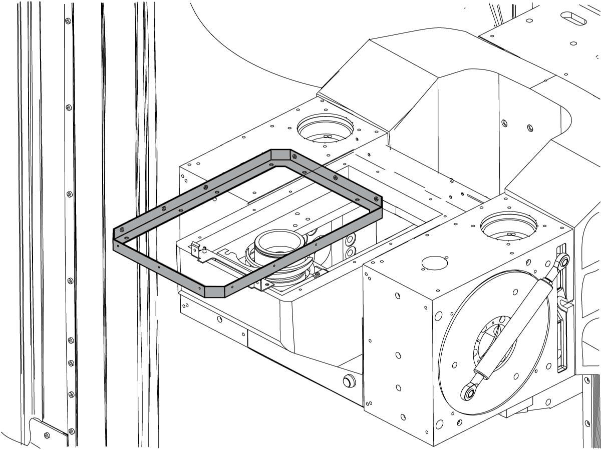
Remove the head cover bracket.

Internal Sheet Metal Removal

1

Jog the X Axis to the center of travel. Jog the Y Axis to the rear of travel.

Press [EMERGENCY STOP].

2

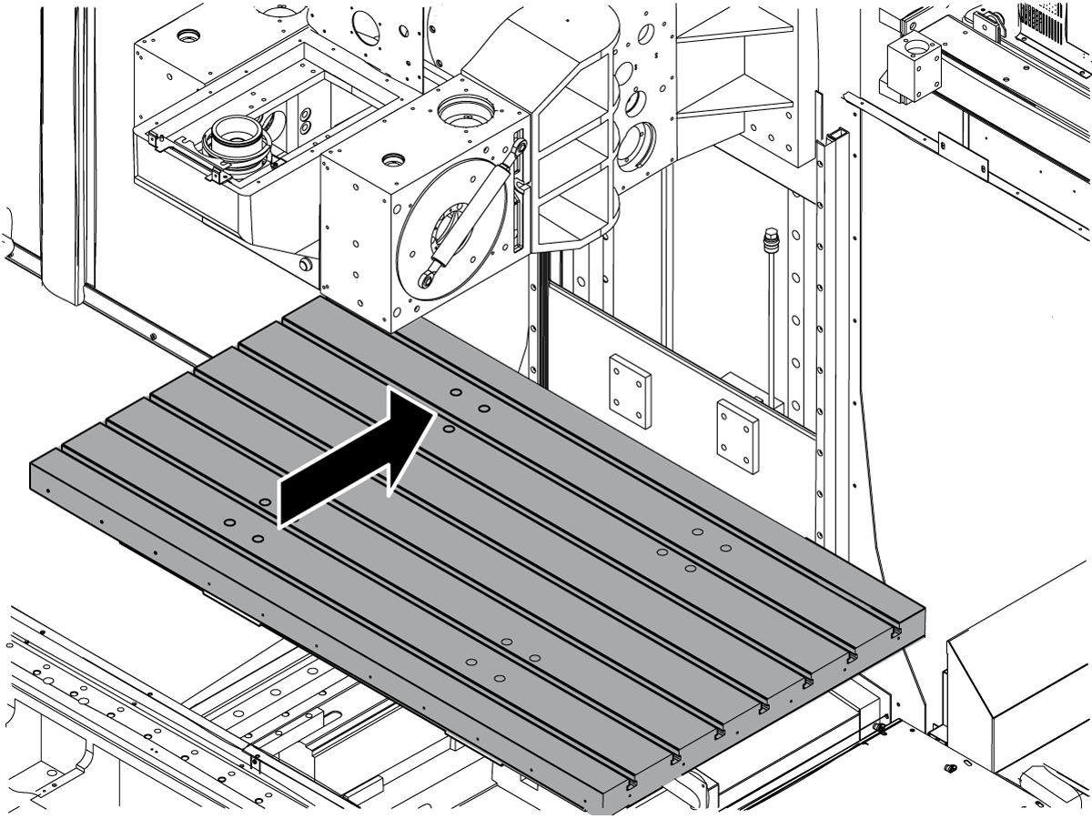
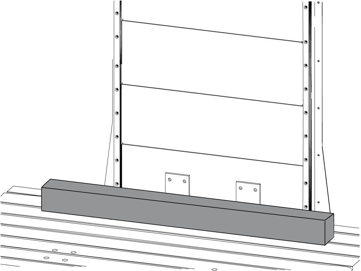
Place a 4' x 4" x 4" piece of wood on the table so that the 450 rotary will rest onto it as you jog the Z Axis down.

3

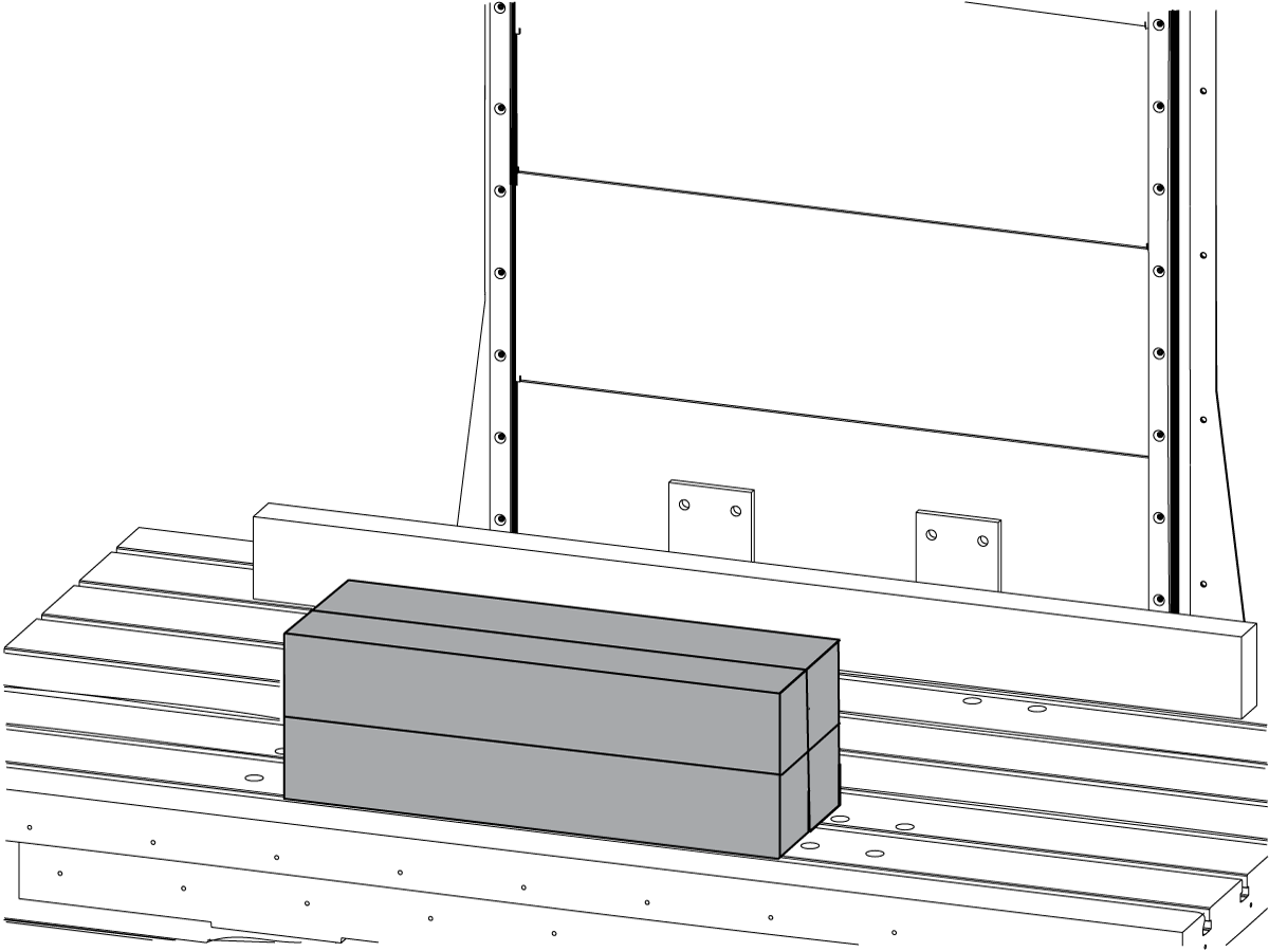
Place (4) 2' x 4" x 4" wood blocks of wood on the table to support the Z Axis under both of the 310 rotaries to keep the head assembly level.

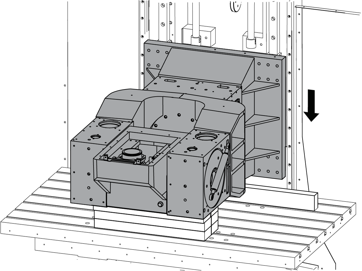
4

Jog the Z Axis down until it rests on the supports.

Press [EMERGENCY STOP]

5

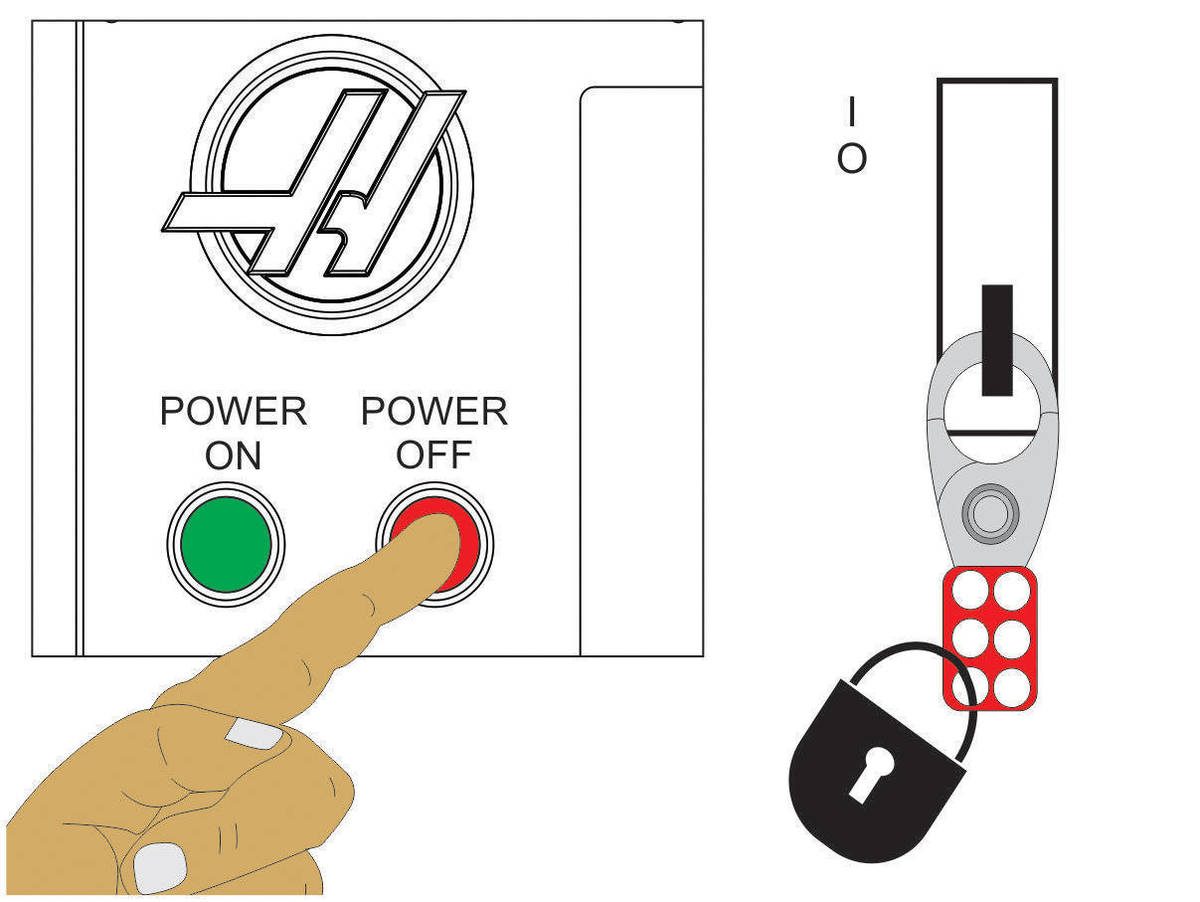
Power off and lockout/tagout machine.

6

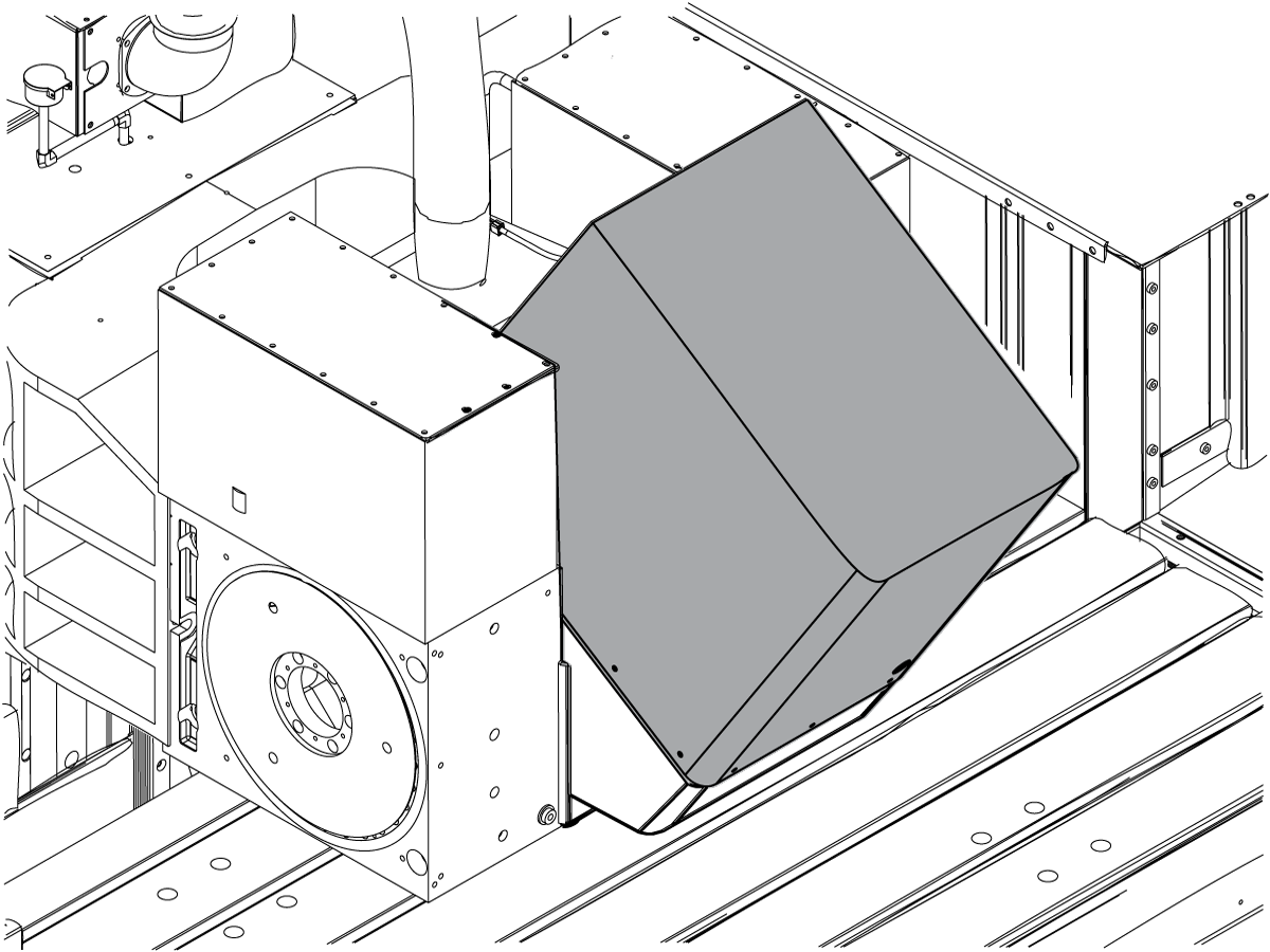
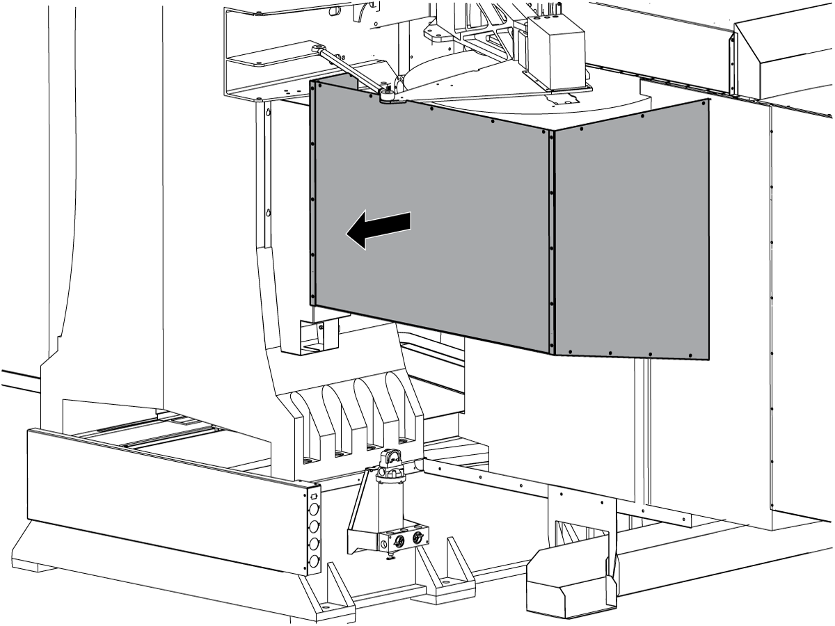
Remove the tool changer housing from the rear of the machine.

7

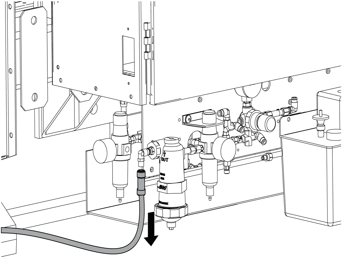
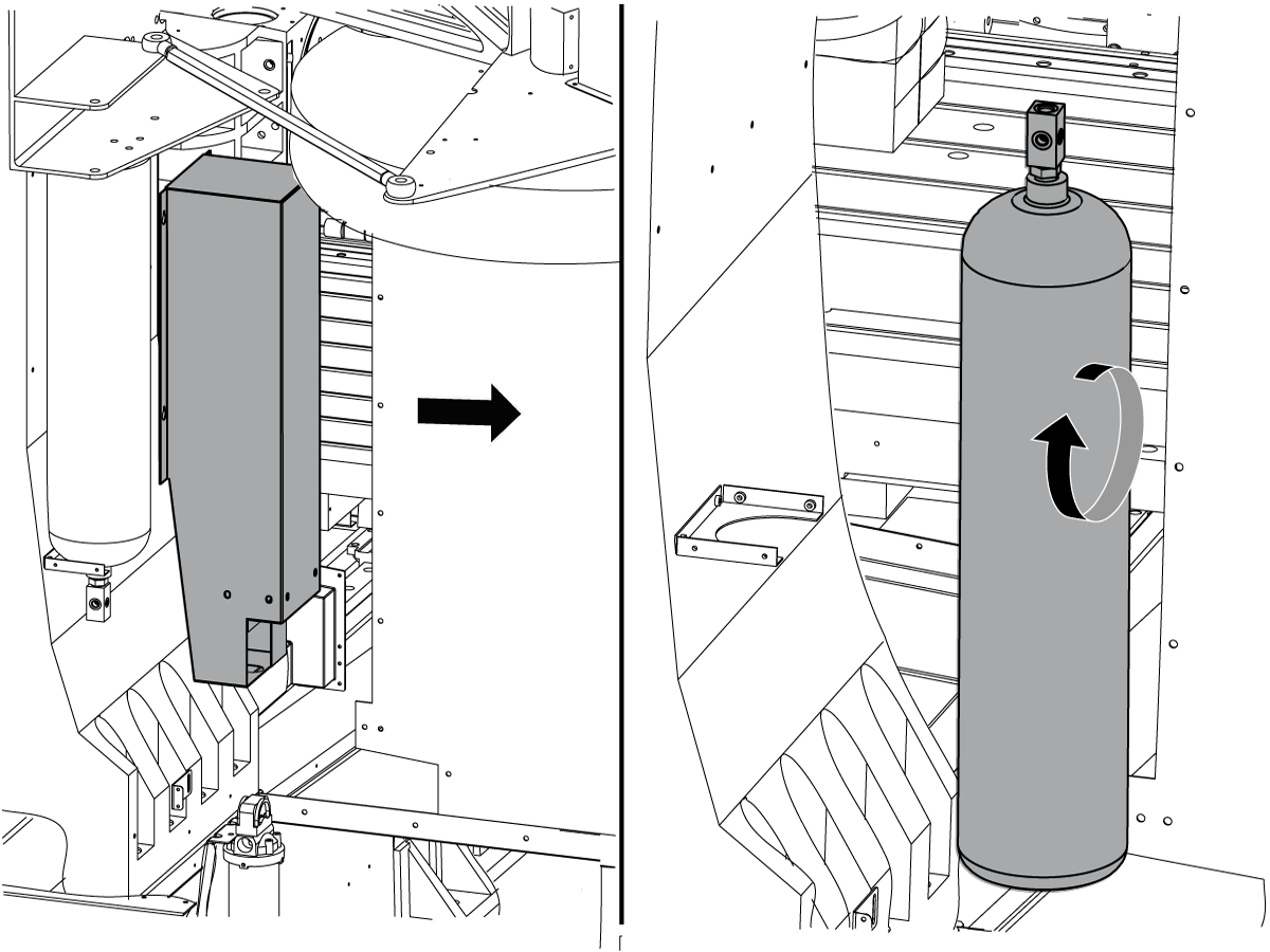
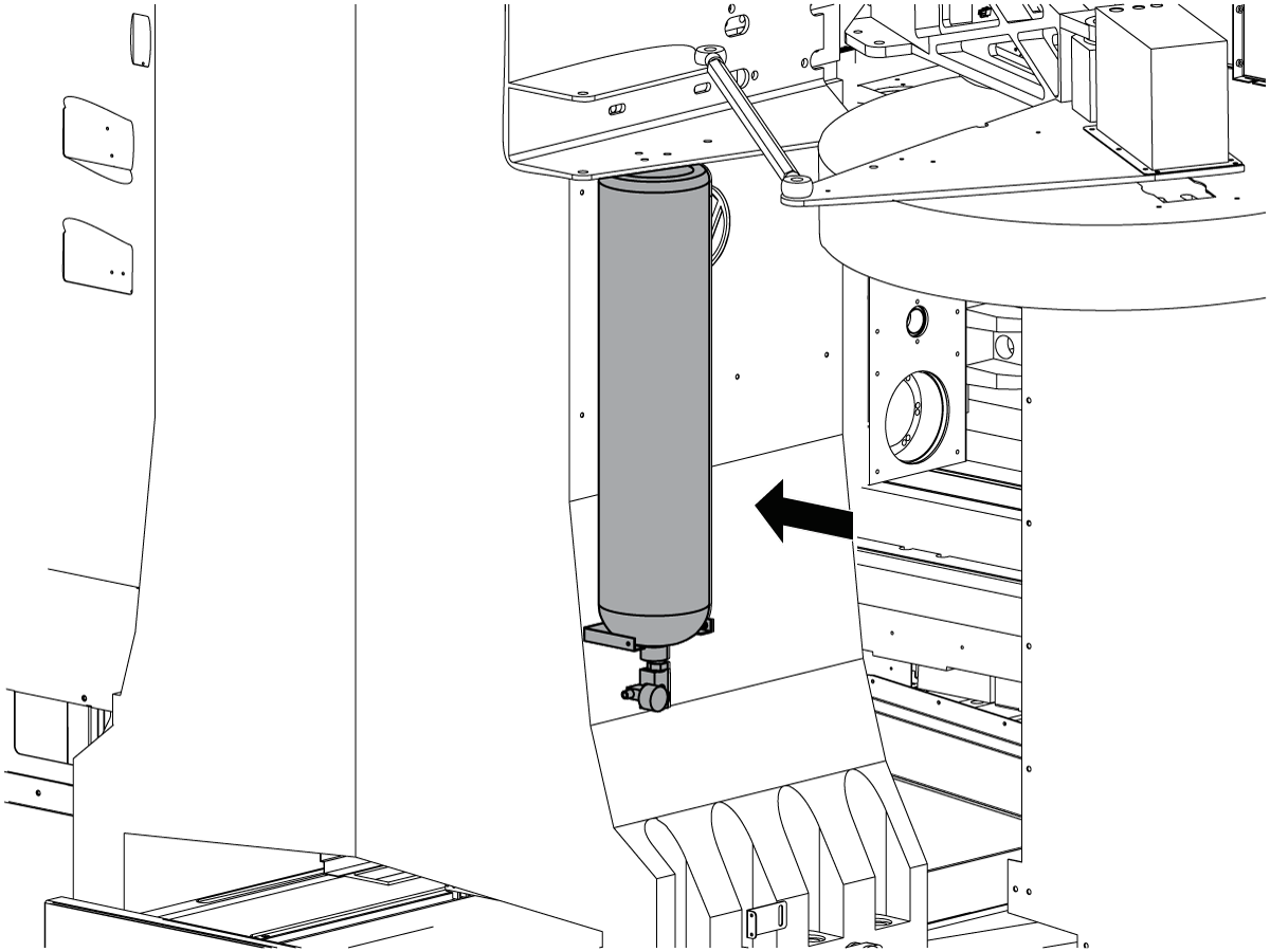
Remove the counterbalance housing(s) and the counterbalance tank(s). Flip over the counterbalance tank(s) so that no oil will be lost during discharge. Discharge each tank to 500 psi.

 Danger: Each tank is under high pressure. Make sure to wear appropriate personal protection equipment. Bleeding and removal should only be done by trained personnel. Refer to the Haas Service Manual for complete instructions on removing the counterbalance tank(s) before attempting this procedure.

 Note: There may be (1) or (2) counterbalance tank/housing assemblies. If there are two assemblies, remove the housings and tanks from both.

 Note: The counterbalance charge/discharge kit is P/N 35-4050A.

8

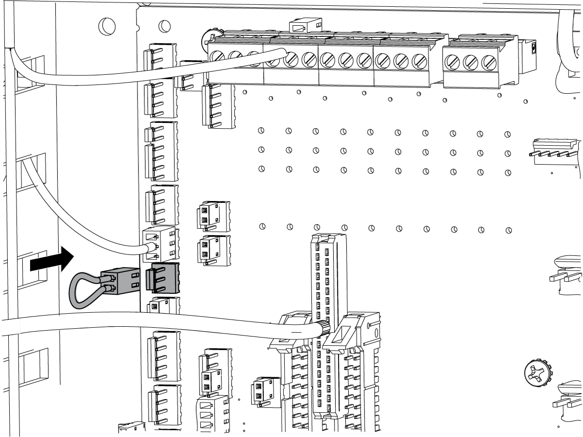
Place a jumper at P6, the counterbalance emergency stop, on the I/O PCB so you can jog the axes.

9

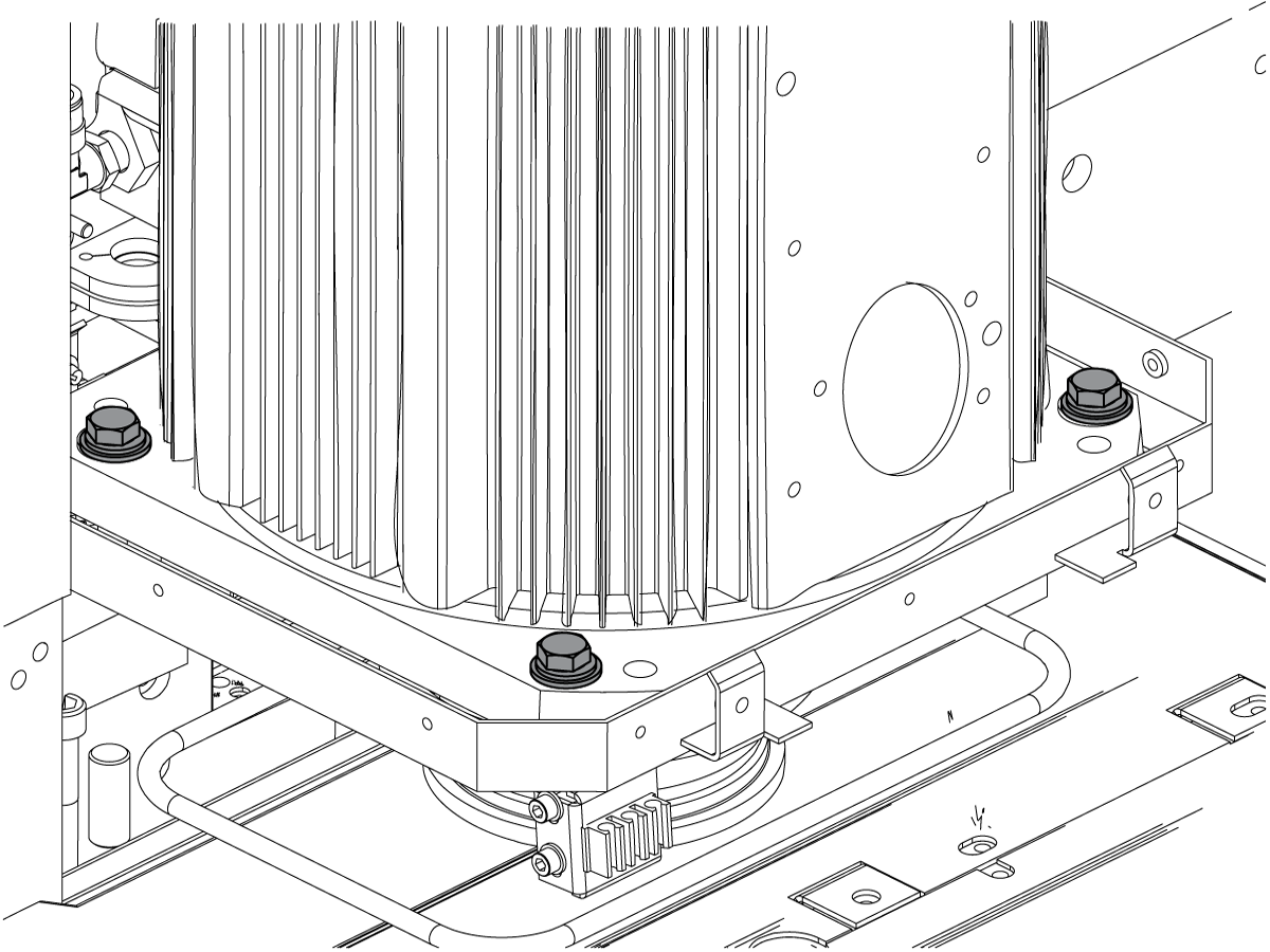
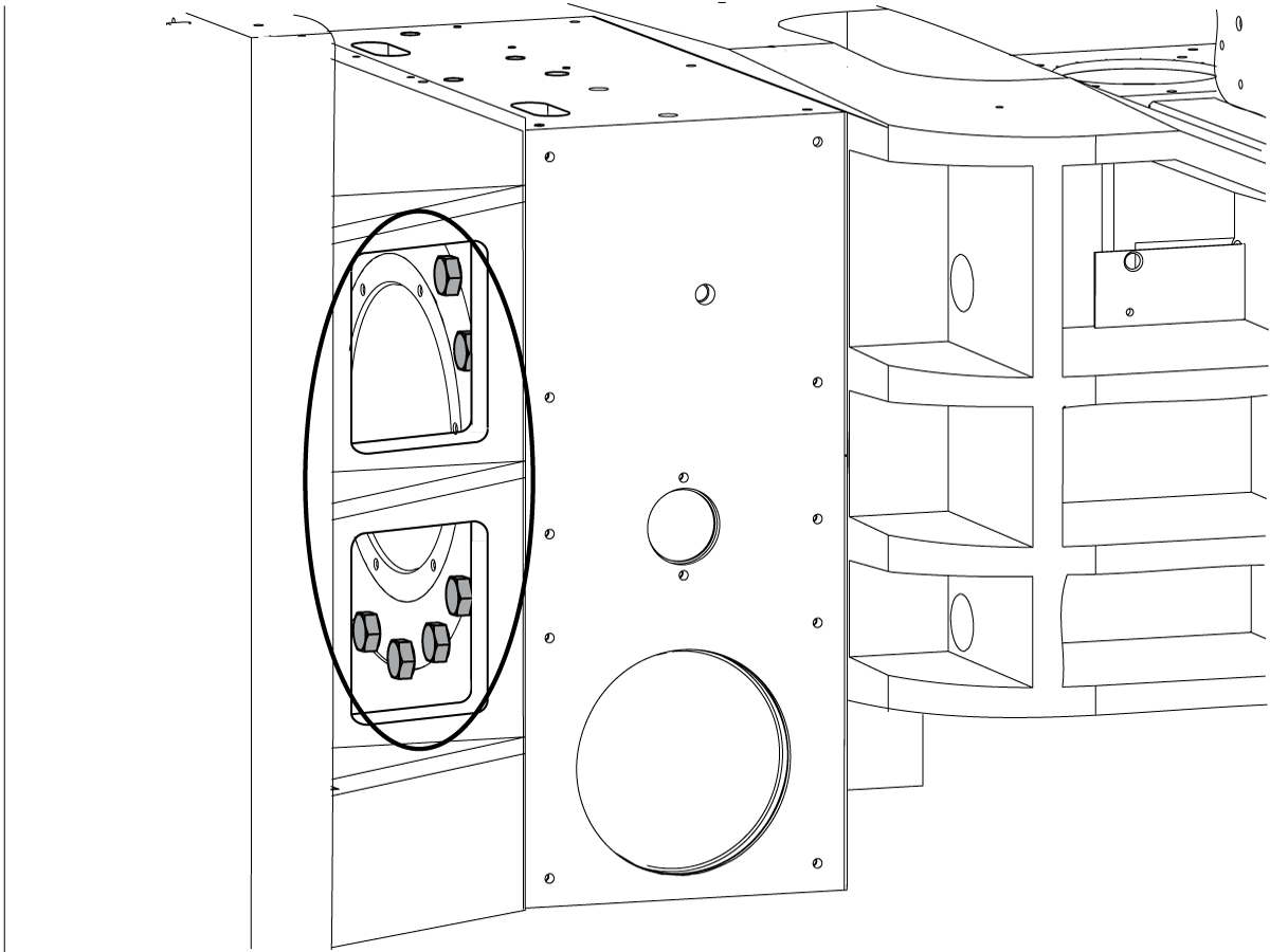
Remove the (12) head retention bolts behind the 450 rotary.
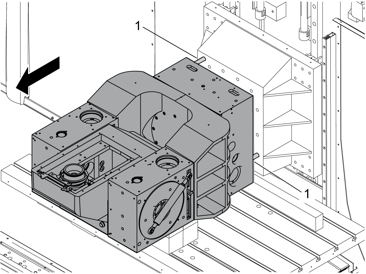
Access these bolts through the side ports on the Z Axis head spacer.

10

Unlock and power on the machine.

11

Slowly jog the Y Axis forward to separate the head from the spacer.

Press [EMERGENCY STOP].

 Caution: Make sure that the Z Axis load does not alarm out. An alarm indicates the head may be binding on the locating pins [1]. If the head binds, jog the Z Axis until the head travels smoothly on the Y Axis.

12

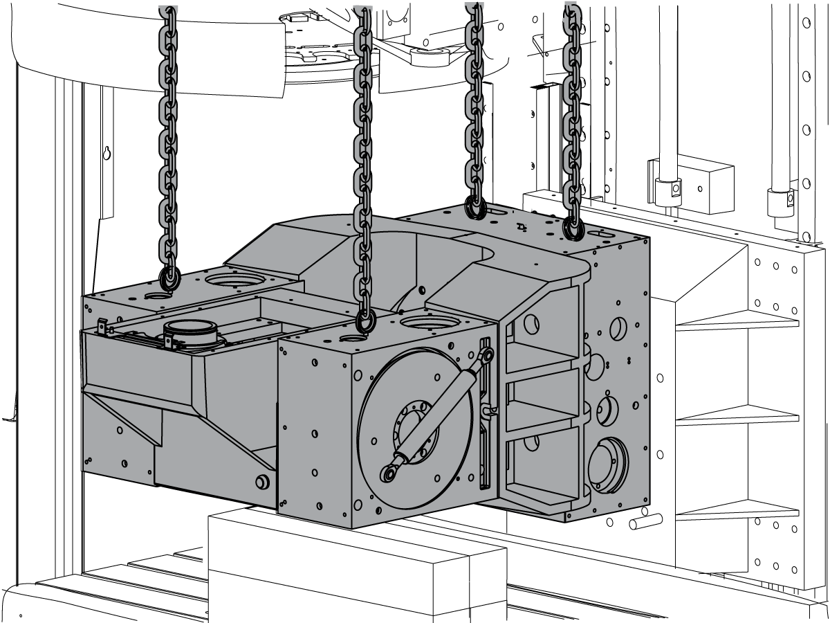
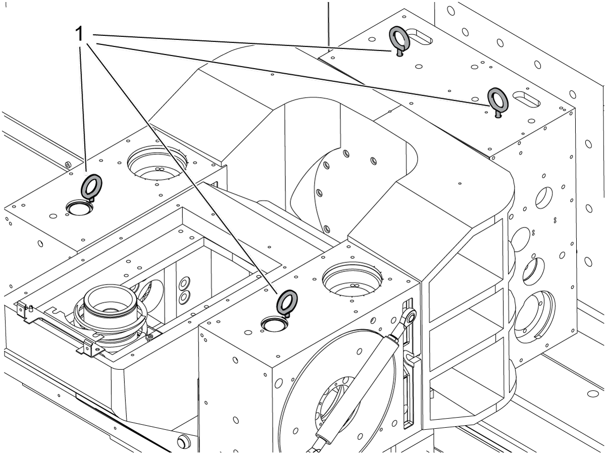
Thread eye bolts [1] into the tapped holes near the centers of each of the three rotary drives.

13

Remove the head assembly from the machine with an overhead crane or forklift.

 Caution: The head assembly weighs in excess of 2,200 lb (998 kg). Make sure to use a lift that is rated for the weight of the head.

Head Assembly Installation

1

Place a 4' x 4" x 4" piece of wood on the table as a support for the 450 rotary on the replacement head.

2

Place (4) 2' x 4" x 4" blocks of wood on the table to support the Z Axis under both 310 rotaries.

3

Insert eye bolts into the threaded holes near the center of each rotary drive unit on the replacement head assembly.

4

Use an overhead crane or forklift to move the replacement head assembly onto the wood supports.

 Caution: The head assembly weighs in excess of 2,200 lb (998 kg). Make sure to use a lift that is rated for the weight of the head.

5

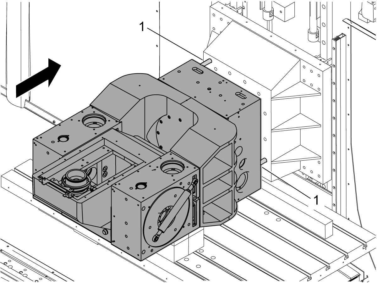
Slowly jog the Y Axis towards the back of the machine to mate the 450 rotary on the back of the head assembly to the Z Axis head spacer. Align the head assembly with the locating pins on the Z Axis head spacer.

 Caution: Make sure that the Z Axis load does not alarm out. An alarm indicates the head may be binding on the locating pins [1]. If the head binds, jog the Z Axis until the head travels smoothly on the Y Axis.

6

Power off and lockout/tagout machine.

7

Remove eye bolts [1] from the head assembly.

8

Attach the head assembly to the Z Axis head spacer with (12) head retention bolts.
Access these bolts through the side ports on the Z Axis head spacer.
Torque the bolts to 160 ft-lb (217 Nm).

9

Install the counterbalance tank(s) and housings. If the mill has two counterbalance tanks, pressurize each to 1250 psi. If there is just one tank, pressurize it to 1550 psi.

 Danger: Each tank is under high pressure. Make sure to wear appropriate personal protection equipment. Installation should only be done by trained personnel. Refer to the Haas Service Manual for complete instructions on installing the counterbalance tank(s) before attempting this procedure.

 Note: There may be (1) or (2) counterbalance tank/housing assemblies. If there are two assemblies, install the housings and tanks for both.

 Note: The counterbalance charge/discharge kit is P/N 35-4050A.

10

Install the tool changer housing.

Spindle Installation

1

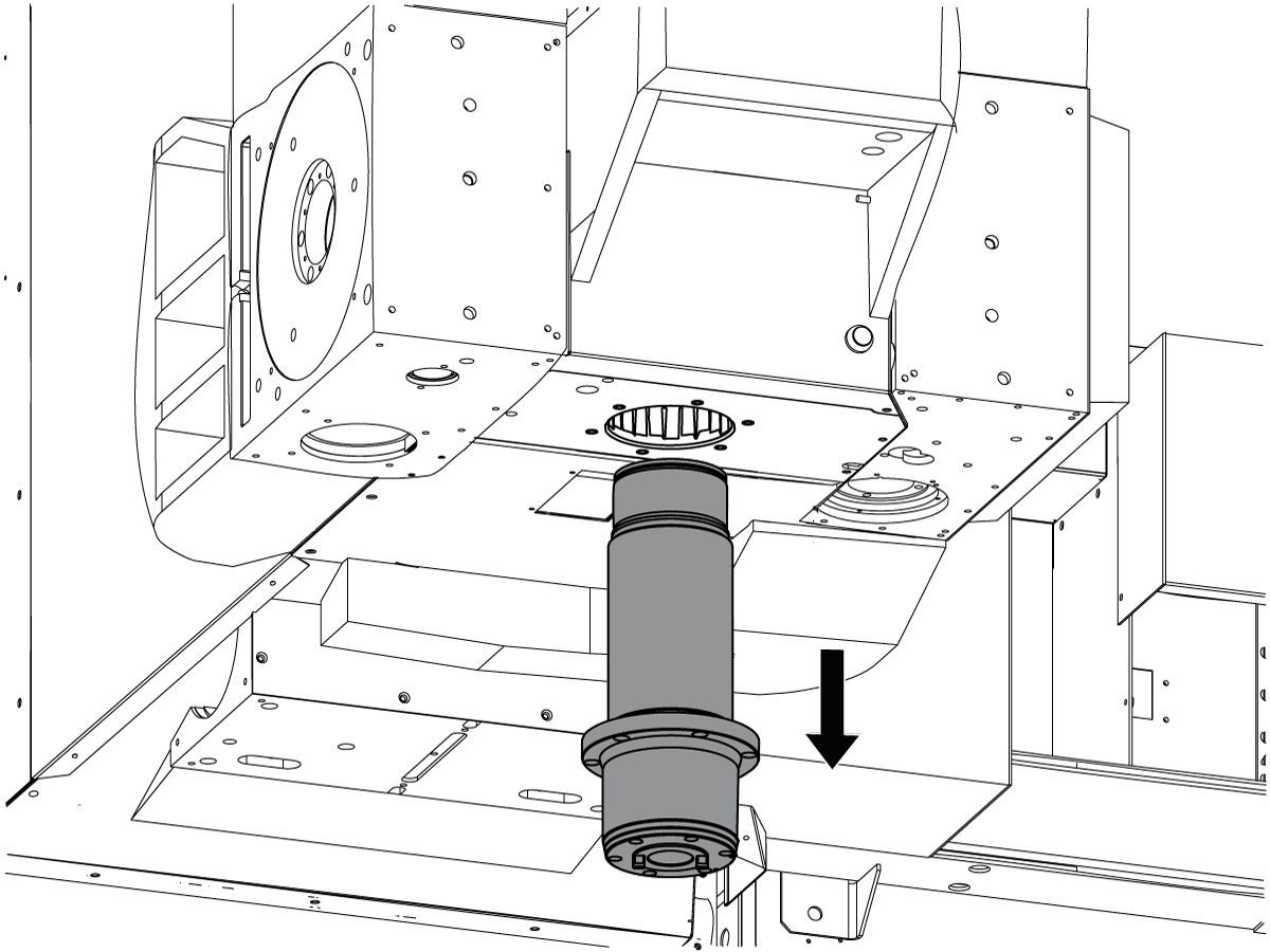
Install the spindle motor.

 Caution: The spindle motor assembly weighs at least 112 lb (55 kg). Make sure to use a lift that is rated for the weight of the spindle motor assembly.

2

Connect all electrical connections to the spindle motor.

3

Insert the spindle into the spindle head casting

4

Tighten the motor retention bolts. Adjust the spindle belt tension.

 Note: Refer to the Haas Service Manual for complete instructions on how to adjust the spindle belt tension.

5

Install the 90 degree fitting to the spindle. Connect the spindle lubrication hose.

6

Install the TRP assembly.

7

Connect the air hose switch and tool clamp switch at the spindle connection plate.

8

Attach the head cover bracket.

9

Attach the bore cover [1] to the left 310 rotary. Attach the fan/head cover back plate [2] assembly to the head. Attach the counterbalance cover [3] to the right 310 rotary.

10

Install the A Axis motor and pulley [1] on the left 310 rotary. Install the fittings from the original head assembly [2] to the right 310 rotary.

11

Feed the motor lead and air hose through the motor cover. Install the motor cover and connect the motor lead and air hose.

 Note: If the machine has Sigma 5 motors, use the adapter cable (P/N 32-2284) to connect the B Axis motor home switch.

12

Attach the motor cover plate to the 450 rotary.

13

Attach the fill tube and the upper sheet metal panel to the top of the 450 rotary.

14

Attach the junction box to the top of the 450 rotary. Attach the junction box cover to the junction box.

15

Lift the lower Z Axis way cover. Attach it to the bottom of the head assembly.

16

Unlock and power on the machine.

17

Rotate the A Axis to gain access to the screws that secure the spindle head cover. Attach the head cover to the machine.\ Rotate the A Axis back to its home position.

18

Attach the (2) 310 rotary motor covers.

19

Set Parameter 76 Low Air Delay to the factory default of 1500.

Set Parameter 278:14 to 1.

Set Parameter 151:3 to 1.

Set Parameter 43:3 to 1.

Cycle power.

Zero all axes and check for any alarms.

Level the machine.

Reset the spindle sweep by adjusting Parameters 212 and 213.

Confirm the head spindle geometry per EA0154.

Determine the new pivot length value per EA0154.

Recently Viewed Items

You Have No Recently Viewed Items Yet

Feedback
Haas Logo

Haas Delivered Price

This price includes shipping cost, export and import duties, insurance, and any other expenses incurred during shipping to a location in France agreed with you as a buyer. No other mandatory costs can be added to the delivery of a Haas CNC Product.

KEEP UP WITH THE LATEST HAAS TIPS AND TECHNOLOGY...

Sign up now!   

HAAS TOOLING ACCEPTS THE FOLLOWING:

  • Service & Support
  • Owners
  • Request Service
  • Operator Manuals
  • Haas Parts
  • Rotary Repair Request
  • Pre-Install Guides
  • Shopping Tools
  • Build & Price a New Haas
  • Available Inventory
  • The Haas Price List
  • CNCA Financing
  • About Haas
  • Accessibility Statement
  • DNSH Statement
  • Export Compliance
  • Careers
  • Certifications & Safety
  • Contact Us
  • History
  • Terms & Conditions
  • Haas Tooling Terms & Conditions
  • Privacy
  • Warranty
  • Haas Community
  • Haas Certification Program
  • Haas Motorsports
  • Gene Haas Foundation
  • Haas Technical Education Community
  • Events
  • Join the Conversation
  • Facebook
  • X
  • Flickr
  • YouTube
  • LinkedIn
  • Instagram
  • TikTok
© 2026 Haas Automation, Inc – CNC Machine Tools
This site is protected by reCAPTCHA and the Google Privacy Policy and Terms of Service apply.

2800 Sturgis Rd., Oxnard, CA 93030
Toll Free: (888) 817-4446 / Fax: 805-278-8554