My Haas Welcome,
!
Haas Tooling MyHaas/HaasConnect Sign In Register Haas Tooling MyHaas/HaasConnect Sign Out Welcome, My Machines Latest Activity My Quotes My Account My Users Sign Out
Find Your Distributor
  1. Select Language
    1. English
    2. Deutsch
    3. Español - ES
    4. Español - MX
    5. Français
    6. Italiano
    7. Português
    8. Český
    9. Dansk
    10. Nederlands
    11. Magyar
    12. Polski
    13. Svenska
    14. Türkçe
    15. 中文
    16. Suomi
    17. Norsk
    18. الإنجليزية
    19. български
    20. Hrvatski
    21. Ελληνικά
    22. Română
    23. Slovenský
    24. Slovenščina
    25. 한국어
    26. 日本語
    27. Українська
  • machines Main Menu
    • Vertical Mills
      Vertical Mills
      Vertical Mills View All
      • Vertical Mills
      • VF Series
      • Universal Machines
      • VR Series
      • VP-5 Prismatic
      • Pallet-Changing VMCs
      • Mini Mills
      • Mold Machines
      • High-Speed Drill Centers
      • Drill/Tap/ Mill Series
      • Toolroom Mills
      • Pocket Mill
      • Compact Mills
      • Gantry Series
      • SR Sheet Routers
      • Extra-Large VMC
      • Double-Column Mills
      • 3+2 Positioning Machines
    • Multi-Axis Solutions
      Multi-Axis Solutions
      Multi-Axis Solutions View All
      • Multi-Axis Solutions
      • Y-Axis Lathes
      • 5-Axis Mills
    • Lathes
      Lathes
      Lathes View All
      • Lathes
      • ST Series
      • Dual-Spindle
      • Box Way Series
      • Toolroom Lathes
      • Chucker Lathe
      • Pocket Lathe
      • Haas Bar Feeders
    • Horizontal Mills
      Horizontal Mills
      Horizontal Mills View All
      • Horizontal Mills
      • 50-Taper
      • 40-Taper
    • Rotaries & Indexers
      Rotaries & Indexers
      Rotaries & Indexers View All
      • Rotaries & Indexers
      • Rotary Tables
      • Indexers
      • 5-Axis Rotaries
      • Extra-Large Rotaries
    • Special Series
      Special Series
      Special Series View All
      • Special Series
      • EU_Series_Redirect
    • Automation Systems
      Automation Systems
      Automation Systems View All
      • Automation Systems
      • Mill Automation
      • Lathe Automation
      • Automatic Parts Loaders
      • Automation Models
    • Desktop Machines
      Desktop Machines
      Desktop Machines View All
      • Desktop Machines
      • Desktop Mill
      • Desktop Lathe
      • Control Simulator, Standard
      • Control Simulator, Premium
    • Shop Equipment
      Shop Equipment
      Shop Equipment View All
      • Shop Equipment
      • Knee Mill
      • Haas Manual Lathes
      • Haas Saws
    • Fabrication Machines
      Fabrication Machines
      Fabrication Machines View All
      • Fabrication Machines
      • Laser Cutting Machines
      • CNC Press Brakes
    • QUICK LINKS Special Series  Special Series 
      EU SERIES EU SERIES BUILD & PRICE | PRICE LIST BUILD & PRICE | PRICE LIST In-Stock Machines In-Stock Machines WHAT’S NEW WHAT’S NEW YOUR FIRST CNC YOUR FIRST CNC
      SHOPPING TOOLS
      • Build & Price a Haas
      • Price List
      • Available Inventory
      • CNCA Financing
      WANT TO TALK TO SOMEONE?

      A Haas Factory Outlet (HFO) can answer your questions, and walk you through your best options.

      CONTACT YOUR DISTRIBUTOR >
  • Options Main Menu
    • The Haas Control Value Option Packages
      Value Option Packages
      Value Option Packages View All
      • Value Option Packages
    • Product Image Spindles
      Spindles
      Spindles View All
      • Spindles
    • Product Image Tool Changers
      Tool Changers
      Tool Changers View All
      • Tool Changers
    • Product Image 4th- | 5th-Axis
      4th- | 5th-Axis
      4th- | 5th-Axis View All
      • 4th- | 5th-Axis
    • Product Image Turrets & Live Tooling
      Turrets & Live Tooling
      Turrets & Live Tooling View All
      • Turrets & Live Tooling
    • Product Image Probing
      Probing
      Probing View All
      • Probing
    • Haas Chip & Coolant Management Chip & Coolant Management
      Chip & Coolant Management
      Chip & Coolant Management View All
      • Chip & Coolant Management
    • The Haas Control The Haas Control
      The Haas Control
      The Haas Control View All
      • The Haas Control
    • Product Image Product Options
      Product Options
      Product Options View All
      • Product Options
    • Product Image Tooling & Fixturing
      Tooling & Fixturing
      Tooling & Fixturing View All
      • Tooling & Fixturing
    • Product Image Workholding
      Workholding
      Workholding View All
      • Workholding
    • Product Image 5-Axis Solutions
      5-Axis Solutions
      5-Axis Solutions View All
      • 5-Axis Solutions
      • 5 Easy Steps to 5-Axis
    • QUICK LINKS Special Series  Special Series 
      EU SERIES EU SERIES BUILD & PRICE | PRICE LIST BUILD & PRICE | PRICE LIST In-Stock Machines In-Stock Machines WHAT’S NEW WHAT’S NEW YOUR FIRST CNC YOUR FIRST CNC
      SHOPPING TOOLS
      • Build & Price a Haas
      • Price List
      • Available Inventory
      • CNCA Financing
      WANT TO TALK TO SOMEONE?

      A Haas Factory Outlet (HFO) can answer your questions, and walk you through your best options.

      CONTACT YOUR DISTRIBUTOR >
  • Why Haas Main Menu
      Discover the Haas Difference
    • Why Haas
    • MyHaas
    • Education Community
    • Industry 4.0
    • Haas Certification
    • Customer Testimonials
  • Service Main Menu
      Welcome to Haas Service
      SERVICE HOME Operator’s Manuals How-To Procedures Troubleshooting Guides Preventive Maintenance Haas Parts Haas Tooling Videos
  • Videos Main Menu
  • Main Menu
    • View All
    • View All
    • View All
    • View All
      • HTEC Curriculum Support
      • Haas Value Option Packages (VOP) Journey
    • View All
      • Haas 10 kg Cobot Package
      • Cobot Kits
      • DC-1 Drill Center
      • CNC Sales News
      • Do More With Your Haas
    • View All
    • View All
      • contact-us-test
      • 4 - AUTOMATION SYSTEMS
      • Carousel-V2
      • expert test
      • Demo_Day_Trident-test
      • Link Test
      • image-sale-tag-test
      • article-list-test
      • Haas 25 kg Robot Package
      • test-algolia-page
    • View All
    • View All
    • View All
    • View All
      • calc-test
    • View All
    • QUICK LINKS Special Series  Special Series 
      EU SERIES EU SERIES BUILD & PRICE | PRICE LIST BUILD & PRICE | PRICE LIST In-Stock Machines In-Stock Machines WHAT’S NEW WHAT’S NEW YOUR FIRST CNC YOUR FIRST CNC
      SHOPPING TOOLS
      • Build & Price a Haas
      • Price List
      • Available Inventory
      • CNCA Financing
      WANT TO TALK TO SOMEONE?

      A Haas Factory Outlet (HFO) can answer your questions, and walk you through your best options.

      CONTACT YOUR DISTRIBUTOR >
  • Haas Tooling Main Menu
  • Haas Service Parts Main Menu

My Haas Welcome,
!
Haas Tooling MyHaas/HaasConnect Sign In Register Haas Tooling MyHaas/HaasConnect Sign Out Welcome, My Machines Latest Activity My Quotes My Account My Users Sign Out
Find Your Distributor
  1. Select Language
    1. English
    2. Deutsch
    3. Español - ES
    4. Español - MX
    5. Français
    6. Italiano
    7. Português
    8. Český
    9. Dansk
    10. Nederlands
    11. Magyar
    12. Polski
    13. Svenska
    14. Türkçe
    15. 中文
    16. Suomi
    17. Norsk
    18. الإنجليزية
    19. български
    20. Hrvatski
    21. Ελληνικά
    22. Română
    23. Slovenský
    24. Slovenščina
    25. 한국어
    26. 日本語
    27. Українська
×

Search Results

Web Pages

Images

    • <
    • 1
    • >

25 - NGC - 8M PCB

Next Gen Control Electrical - Service Manual


  • 1 - NGC - Introduction
  • 2 - NGC - Activation
  • 3 - NGC - Software Update
  • 4 - NGC - Firmware Update
  • 5 - NGC - Configuration
  • 6 - NGC - Error Report and Backup
  • 7 - NGC - Main Processor
  • 8 - NGC - I/O and TC PCB
  • 9 - NGC - CAN Systems and Autodoor
  • 10 - NGC - Servo Motors and Axis Cables
  • 11 - NGC - 4th and 5th Axis
  • 12 - NGC - Servo Amplifiers
  • 13 - NGC - Vector Drive
  • 14 - NGC - Regen
  • 15 - NGC - 320V Power Supply
  • 16 - NGC - Wye / Delta
  • 17 - NGC - Circuit Breaker and Transformer
  • 18 - NGC - PSUP PCB
  • 19 - NGC - SKBIF and LCD Monitor
  • 20 - NGC - Remote Jog Handle
  • 21 - NGC - 115V LED - WorkLights
  • 22 - NGC - CabCool
  • 23 - NGC - MyHaas
  • 24 - NGC - Networking
  • 25 - NGC - 8M PCB
  • 26 - NGC - Robot and Automation
  • 27 - NGC - Machine Data Collection
  • 28 - NGC - Control Icons
  • 29 - NGC - Sensors and Switches
  • 30 - NGC - USB
  • 31 - NGC - Keypad
  • 32 - NGC - Broken Tool Detection
  • 33 - NGC - IPFDM PCB
  • 34. NGC - LVPS
  • 35 - NGC - Camera Monitor System
  • 36 - NGC - High Intensity Lights
  • 37 - NGC - 24V LED - Worklights
  • 38 - NGC - Mill - Rotary Scale Cable Installation

Go To :

  • 25.1 - 8M PCB - Installation
  • 25.2 - 8M PCB - Troubleshooting
  • 25.3 - M-Finin Option - Installation

25.1 - 8M Option - Installation

Recently Updated

8M Option - Installation


AD0162

Introduction

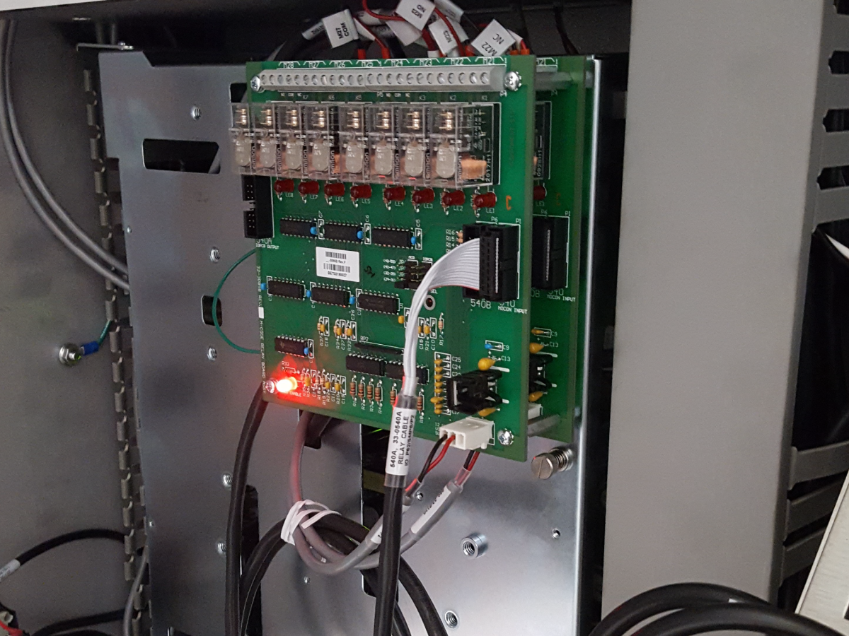
This procedure shows you how to install the 8M Option . 

Machine Compatibility:

  • Classic Haas Control:  Mill 8.29 or higher / Lathe 2.16 or higher
     NOTE: M59/M69 Functionality was added in Mill 11.14 and higher.
  • Next Generation Control:  All Versions
  • Hinge door over the I/O PCB.
    IMPORTANT: 93-1000573 I/O DOOR ASSY HINGED order the hinge door if it did not come in the kit.

Document Applies to these Parts:

  • 93-1000313 8 SPARE M FUNCTIONS - NGC
  • 93-3319 8M FI KIT W/ HINGE DOOR 
  • 93-1157A 8M Field Install Kit - CHC

Multiple 8M PCBs Installation

Second 8M PCB Installation:

  • 93-3913 2ND 8M SPARE NGC ADDON      

 NOTE: This service kit is intended to upgrade the 8M PCB Bank #2 to include additional spare outputs (spare outputs are restricted for machines with C-APL). This 8M PCB board will be installed directly on top of the first 8M PCB board.  

Third 8M PCB Installation:

  •   NOTE: There is no third 8M PCB installation kit. In order to install a third 8M PCB, you will need to order an additional single kit installation (93-1000313 NGC kit or 93-1157A CHC kit) and combine the 12VDC power connector. 

Hinge Door - Installation

This section shows you how to install the hinge door on the I/O PCB.   Skip this section If you machine already has a hinge door installed.  

1

Push [POWER OFF].

Set the main circuit breaker to the OFF position.

Lock the main circuit breaker. Use an approved lock with an approved safety tag.

Caution: When you handle a PCB, you must wear an Electrostatic Discharge (ESD) strap.

2

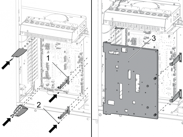
Remove the I/O PCB cover and standoffs from the control cabinet.

Install the (4) screws  to attach the I/O PCB.

Install the (4) I/O PCB brackets [1].

Install the (8) screws [2] to support the brackets.

Install the Hinge Door [3] for the I/O PCB.

8M PCB - Installation

1

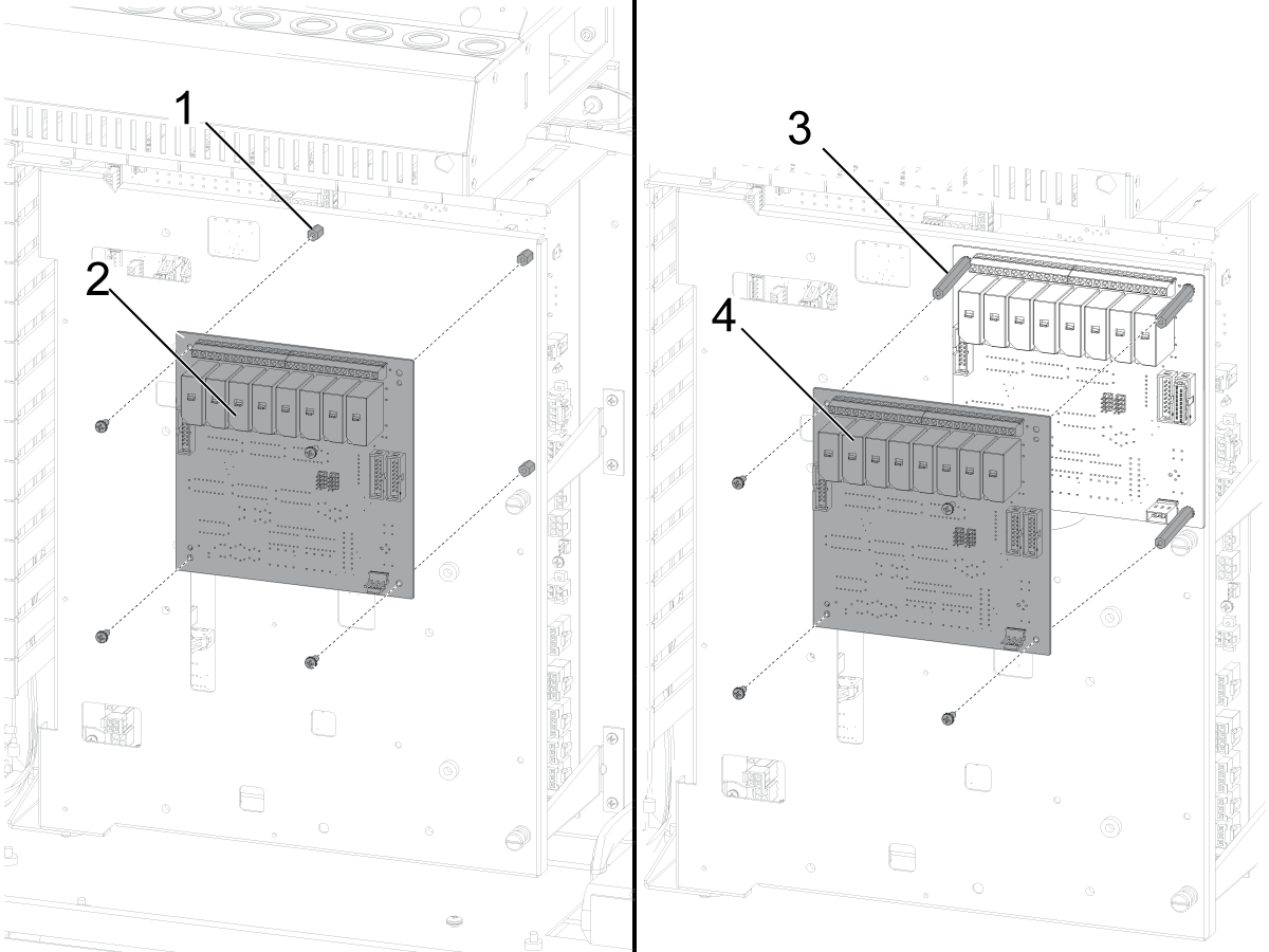
For a single 8M PCB installation.

Install the (4) standoffs [1] to the hinge door .

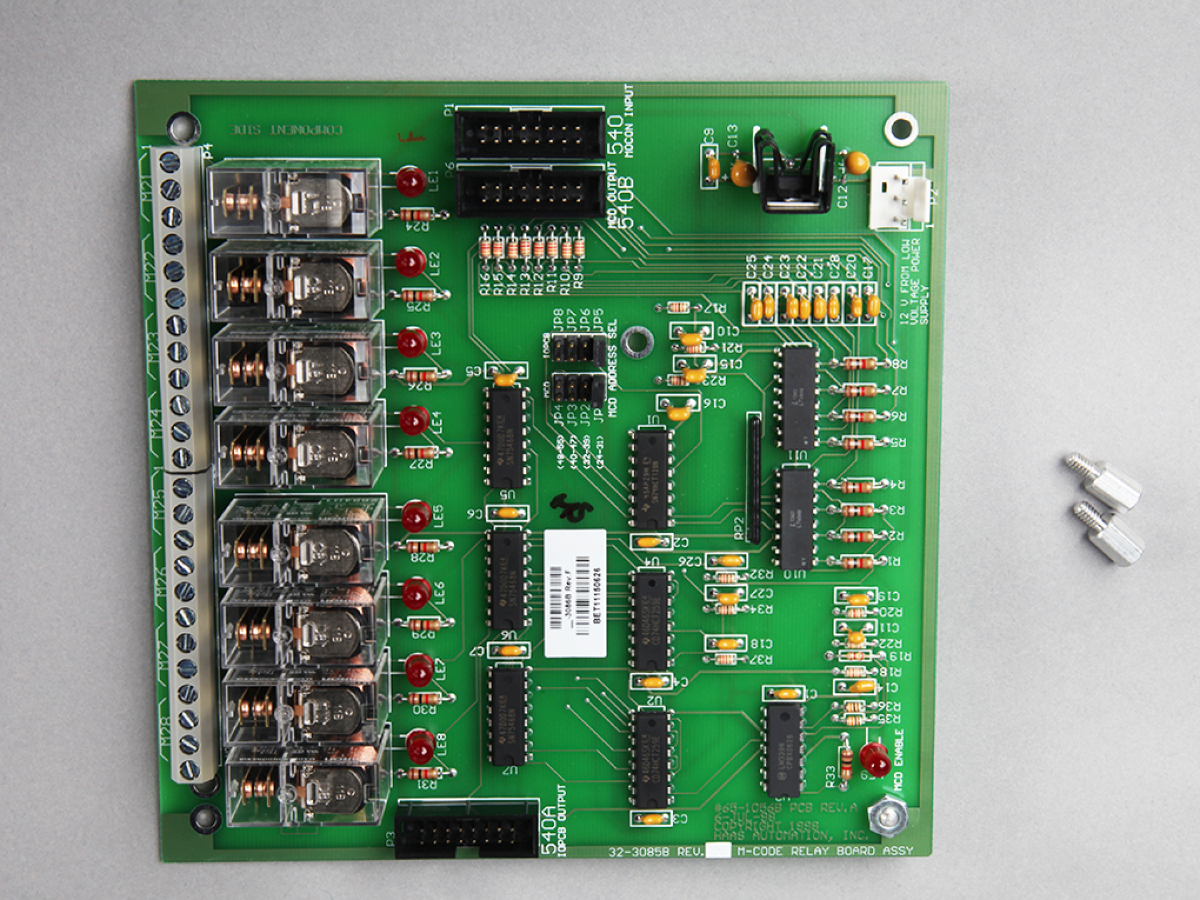
Install the 8M PCB [2].

Refer to the next section for how to wire and set the jumpers.

Multiple 8M PCB installation

Second 8M PCB Installation.

Remove the existing 8M PCB mounting screws.

Install  the (4) 1 1/4" standaoffs [3].

Install the sencond 8M PCB [4].

Refer to next section for how to wire and set the jumpers.

Third 8M PCB Installation

Choose a location on the hinge door. 

Using the 8M PCB as a template mark the missing holes on the hinge door.

Drill and tap new holes.  (tap size #6-32).

Important:  To protect the I/O PCB from the metal particles,  remove the hinge door before you drill into it.


2

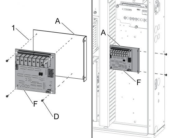
This step tells you how to install the BRACKET [A] and PCB [F] on Office Mill and Office Lathe machines:

Install the (4) standoffs [1] to the BRACKET [A].

Install the PCB [F].

Use the (4) BOLTS [D].

Install the PCB [F] and BRACKET [A] to the right panel of the control cabinet.

Next Generation Control - Installation

1

NGC - Next Generation Control: 

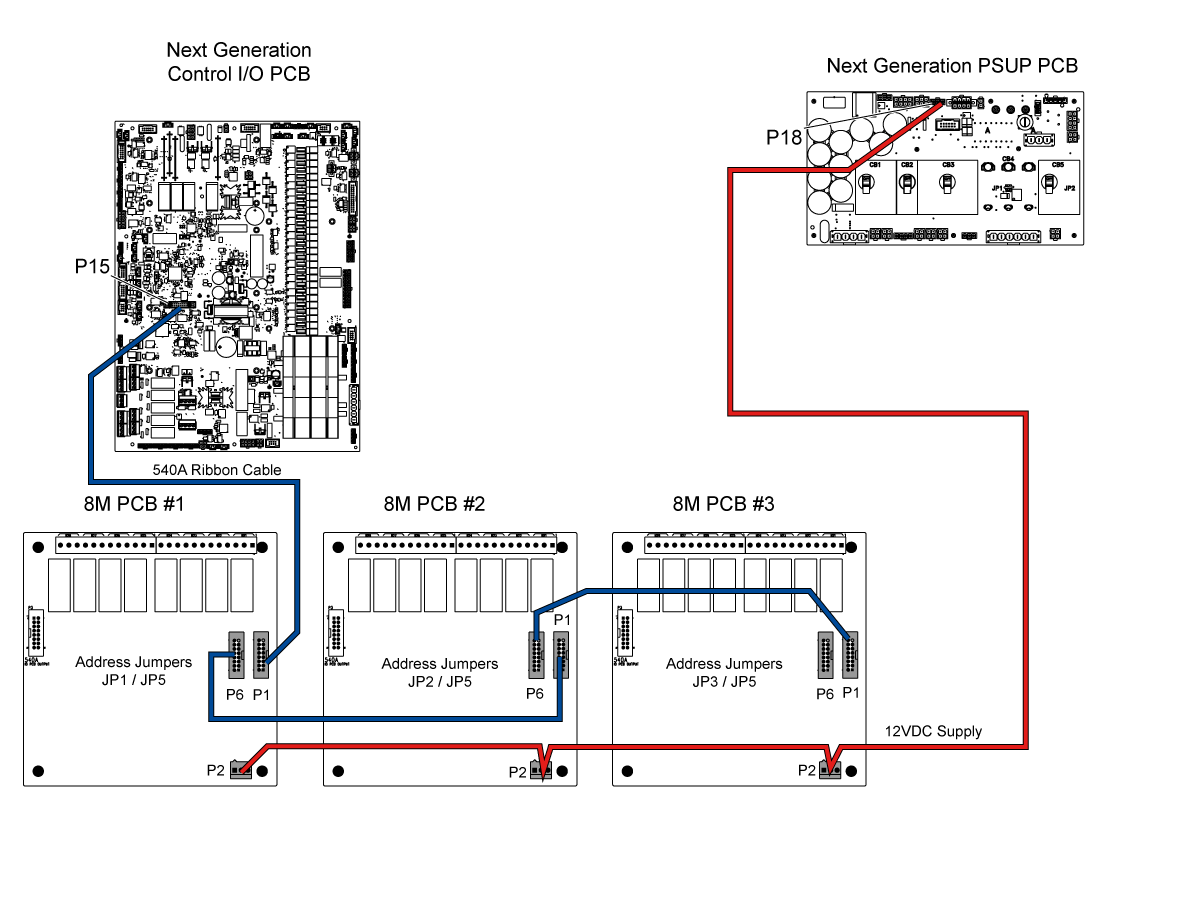
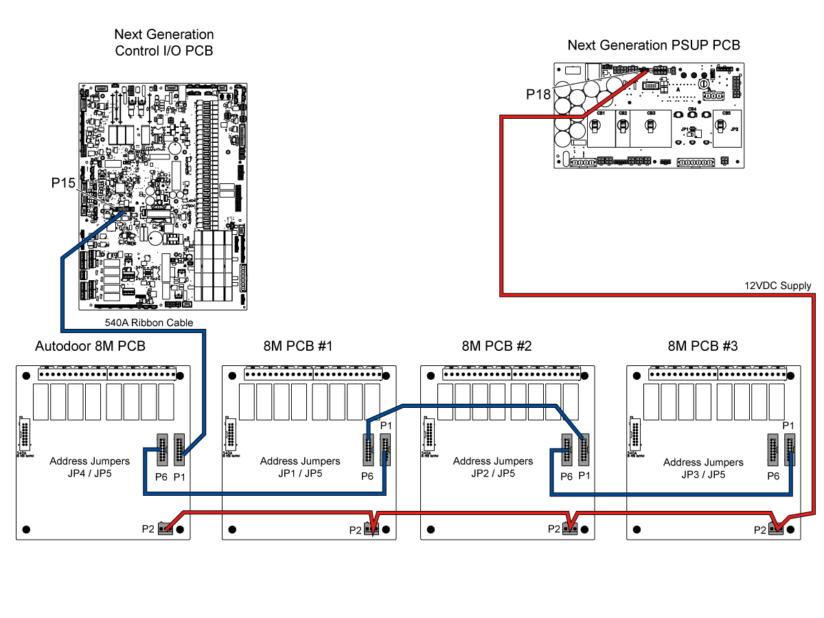
You can connect multiple 8M PCB cards daisy chained.  See illustration for cable connections.

Machines without a Non-Servo Autodoor option.

  • For 8M PCB # 1 set jumpers at JP1 and JP5 
     Note: This jumper configuration uses Outputs 90 through 97.
  • For 8M PCB # 2 set  jumpers at JP2 and JP5
     Note: This jumper configuration uses Outputs 103 through 110. There may be a function limitation with this configuration, refer to the M-Code Relay Function - NGC reference document for more information.
  • For 8M PCB #3 set jumpers at JP3 and JP5
     Note: This jumper configuration uses Outputs 79 through 86.

Machines with a Non-Servo Autodoor option.

  • Autodoor 8M PCB:  A 8M PCB is installed at the factory when a machine is ordered with the Autodoor option.  The address jumpers JP4 and JP5 are set from the factory. 
     Note: Do not change this jumper configuration.  This 8M PCB is used for the non servo autodoor operation.
  • For 8M PCB # 1 set  jumpers at JP1 and JP5
     Note: This jumper configuration uses Outputs 90 through 97.
  • For 8M PCB #2 set jumpers at JP2 and JP5
     Note: This jumper configuration uses Outputs 103 through 110. There may be a function limitation with this configuration, refer to the M-Code Relay Function - NGC reference document for more information.
  • For 8M PCB #3 set jumpers at JP3 and JP5 
     Note: This jumper configuration uses Outputs 79 through 86.

Refer to these documents for 8M option applications:

  • M-Code Relay Function - NGC
  • Robot Integration Aid - NGC
  • Machine Data Collection - NGC

25.2 - 8M PCB - Troubleshooting Guide

Recently Updated

8M PCB - Troubleshooting Guide - NGC


TG0021

Introduction

The 8M Relay PCB is an option that adds (8) additional outputs to the I/O PCB. Additional outputs can be used to activate probes, auxiliary pumps, or clamping devices.

Please refer to the user manual for detailed descriptions on all of the M-Codes and functions related to the 8M option.

 Note: The 8M PCB option does not provide an output voltage, it only provides an NC or NO switch point for the user interface.

There are two main uses of the 8M:

  • Turn relays on (M59) and off (M69)
  • Turn relays on while waiting for an external finish signal before turning relay off (Mill: M29, Lathe: M129)

Each M code is followed with a P code. The M codes turns the relay on/off while the P code addesses the discrete relay being turned on/off.  For more information, refer to the M-Code Relay Function - NGC and Robot Integration Aid - NGC reference document.

Symptom Table

Symptom Possible Cause Corrective Action
The M21-M28 relays on the 8M PCB do not activate when commanded. There is a problem with the power to the 8M PCB. Troubleshoot the power to the 8M PCB.
The M21-M28 relays on the 8M PCB do not activate but their corresponding LED indicates they are on. There is a problem with the relays. Make sure the relays are not damaged.
The relays on the M-code PCB are not resetting with [RESET], [E-STOP] or Alarm. The software is outdated See the Reset Behavior section below.
For machines built after 2019 without pallet changer: Some P codes on Bank #2 do not activate when commanded.  Bank #2 only uses outputs P106 - 109 for this configuration.  For more outputs, switch bank #2 with bank #3 in order to use outputs P79 - P86.

Input Voltage Inspection

Corrective Action:

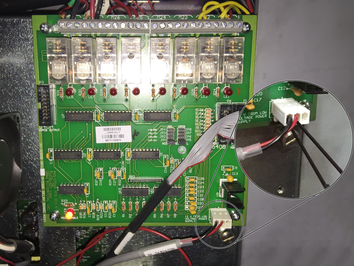
Measure the voltage at P2 on the 8M PCB. Use a multimeter with needle-tip probes. The voltage must be 12 VDC.

 Note: Do not measure the voltage with the cable disconnected.

If the voltage is not correct, measure the voltage at P35 on the PSUP PCB. The voltage must be 12 VDC.

If the voltage is correct, cable 860 is at fault. If the voltage is not correct, troubleshoot the PSUP PCB.

Relay Inspection

Corrective Action:

Make sure the relays are not damaged. Make sure there is continuity between the contacts on the terminal block:

  • Disconnect the cables from the terminal that is at fault.
  • Activate the relay. Check for continuity across the Normally Open (NO) contact and the Common (COM) contact.
  • De-activate the relay. Check for continuity across the Normally Closed (NC) contact and the (COM) contact.

Make sure the coil of the relay is not open:

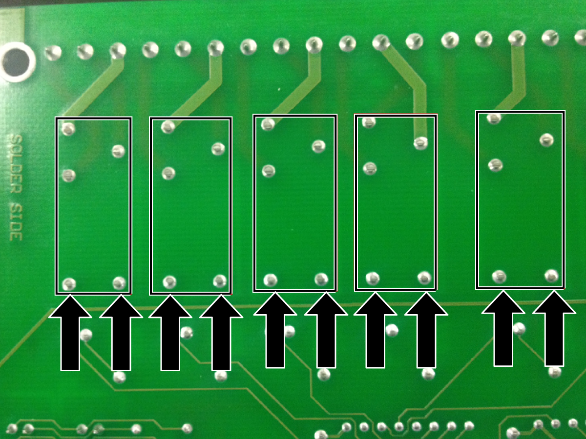
  • Remove the 8M PCB. On the back of the 8M PCB, measure the resistance across pins 1 and 5 of the relay at fault.
  • If the measurement is open, the coil of the relay is open. The 8M PCB is at fault.

Electrical Diagram

25.3 - M-FININ - Option - Installation

Recently Updated

M-FININ - Option - Installation


AD0549

Introduction

This optional cable assembly from the I/O board of the Haas machine to a connector on the side of the control cabinet provides M-code/MFIN capability for controlling external devices. Allows an M-code to pause a CNC program, send a start signal to the device, and then resume the program when an MFIN (finished) signal is received from the device.

Once installed an accessory with a 4-pin male Amphenol 703-91-T-3300-1 screwlocking plug (Haas P/N 74-1510) can be controlled by the CNC machine.

This Document Applies to the following Kits:

  • 93-APC-READY AUTOMATIC PALLET CHANGER READY
  • 93-1000274    AUTOMATIC PALLET CHANGER READY
  • 93-1000651    AUTOMATIC PALLET CHANGER READY
  • 93-2395    AUTOMATIC PALLET CHANGER READY, NGC
  • 93-2396    CABLE ASSY FOR MCODE/MFIN CAPA, NGC
  • 93-1000307    M-CODE/MFIN CABLE ASSEMBLY
  • 93-MFININ    CABLE ASSEMBLY FOR MCODE/MFIN CAPA

Installation

Turn off power to the machine and open the control cabinet door.

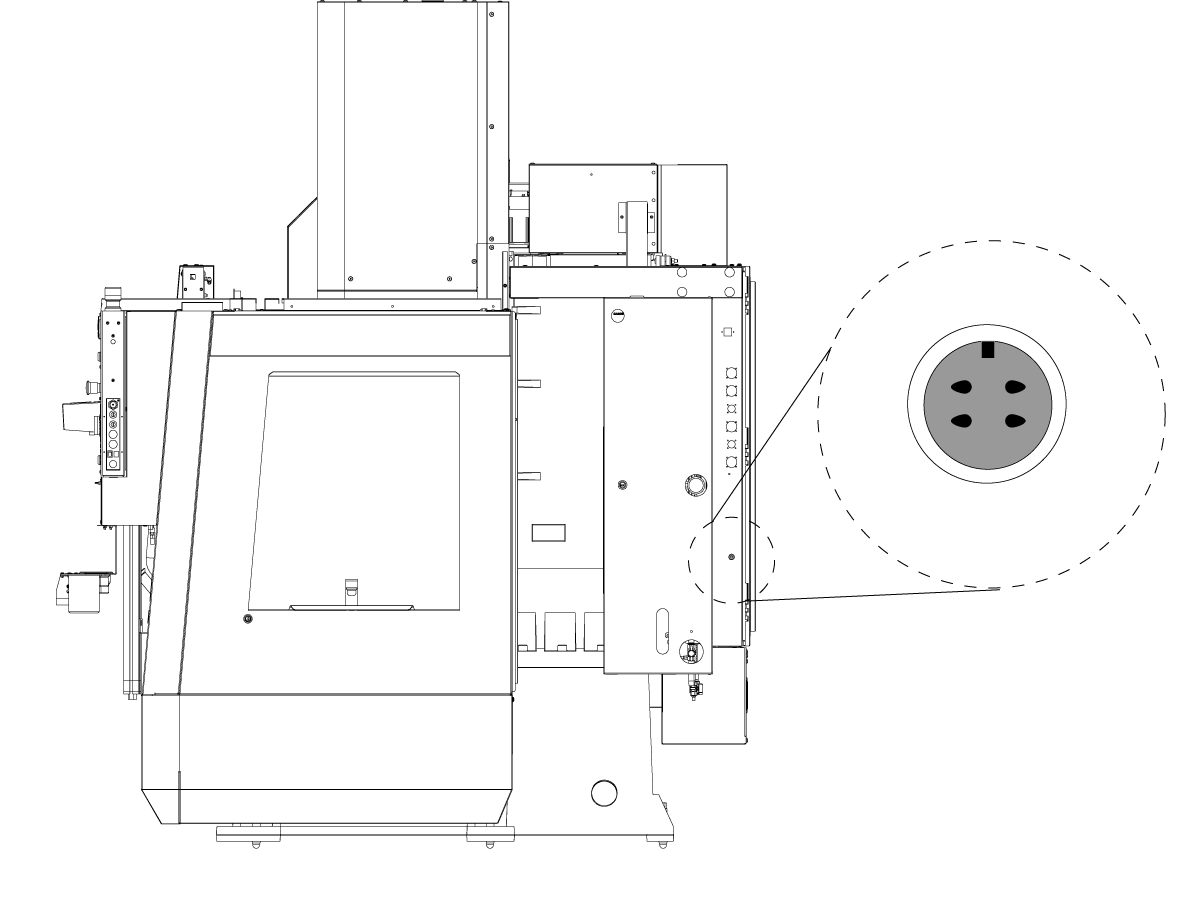
Remove the plug from the side of the control cabinet.

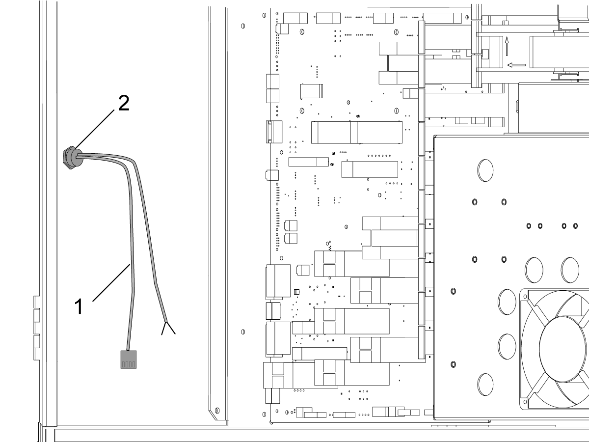
Install the M-FIN connector in the side of the control cabinet. To do so, remove the nut from the plug, insert the wires [1] through the holes from the outside of the control cabinet.

Thread the wires through the nut and tighten the nut [2] against the control cabinet.

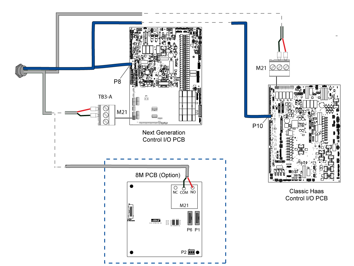
Connect the two wires. One pair of wires has a plug on it which is installed to P8 on the NGC I/O PCB.
Note: For Classic Haas Machine connect the plug to P10 on the I/O PCB.

The second pair of wires is made up of a red and black wire. These two wires are installed differently depending on machine options.

If the machine Does Not have an M-Code relay board the wires are connected to the M21 relay on the I/O PCB. Connect the red wire to the M21 N/O (normally open) terminal and the black wire to the M21 COM (common) terminal.

If the machine Does have an M-Code relay board the wires are connected to the M21 relay on the M-Code Relay Board. Connect the red wire to the N/O (normally open) terminal and the black wire to the COM (common) terminal.

Operation

Accessories are connected to the CNC control through the M-Fin plug. The accessories are then commanded using the M-Codes. 

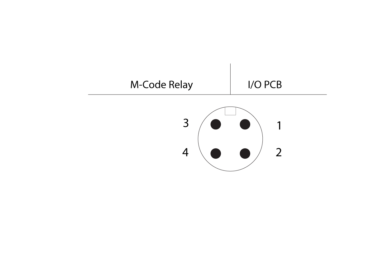
M-FIN Plug Diagram

  1. Signal (MFIN Input)

    Important: Use a relay to activate this input. Do not apply voltage to this input. When a M-Fin signal is sensed the diagnostic #18 M_FIN_INPUT bit will toggle.

  2. Ground
  3. Normally Open (N/O)
  4. Common (COM)

References

8M Option - Installation - AD0162

Robot Integration Aid - NGC

Recently Viewed Items

You Have No Recently Viewed Items Yet

Feedback
Haas Logo

Haas Delivered Price

This price includes shipping cost, export and import duties, insurance, and any other expenses incurred during shipping to a location in France agreed with you as a buyer. No other mandatory costs can be added to the delivery of a Haas CNC Product.

KEEP UP WITH THE LATEST HAAS TIPS AND TECHNOLOGY...

Sign up now!   

HAAS TOOLING ACCEPTS THE FOLLOWING:

  • Service & Support
  • Owners
  • Request Service
  • Operator Manuals
  • Haas Parts
  • Rotary Repair Request
  • Pre-Install Guides
  • Shopping Tools
  • Build & Price a New Haas
  • Available Inventory
  • The Haas Price List
  • CNCA Financing
  • About Haas
  • Accessibility Statement
  • DNSH Statement
  • Export Compliance
  • Careers
  • Certifications & Safety
  • Contact Us
  • History
  • Terms & Conditions
  • Haas Tooling Terms & Conditions
  • Privacy
  • Warranty
  • Haas Community
  • Haas Certification Program
  • Haas Motorsports

  • Gene Haas Foundation
  • Haas Technical Education Community
  • Events

  • Join the Conversation
  • Facebook
  • X
  • Flickr
  • YouTube
  • LinkedIn
  • Instagram
  • TikTok
© 2026 Haas Automation, Inc – CNC Machine Tools

This site is protected by reCAPTCHA and the Google Privacy Policy and Terms of Service apply.

2800 Sturgis Rd., Oxnard, CA 93030
Toll Free: (888) 817-4446 / Fax: 805-278-8554