×

Search Results

Web Pages

Images

    • <
    • 1
    • >
  • machines
    • Haas Vertical Mills
      Vertical Mills
      • Vertical Mills
      • VF Series
      • Universal Machines
      • VR Series
      • Pallet-Changing VMCs
      • Mini Mills
      • Mold Machines
      • Drill/ Tap/ Mill Series
      • Toolroom Mills
      • Compact Mills
      • Gantry Series
      • Vertical Mill/Turn
      • Extra-Large VMC
      • Double-Column Mills
      • Desktop Mill
      • Mill Auto Parts Loader
    • Product Image
      Multi-Axis Solutions
      • Multi-Axis Solutions
      • Y-Axis Lathes
      • 5-Axis Mills
    • Haas Lathes
      Lathes
      • Lathes
      • ST Series
      • Dual-Spindle
      • Toolroom Lathes
      • Chucker Lathe
      • Haas Bar Feeder V2
      • Lathe Auto Parts Loader
    • Haas Horizontal Mills
      Horizontal Mills
      • Horizontal Mills
      • 50-Taper
      • 40-Taper
    • Haas Rotaries & Indexers
      Rotaries & Indexers
      • Rotaries & Indexers
      • Rotary Tables
      • Indexers
      • 5-Axis Rotaries
      • Extra-Large Rotaries
    • Product Image
      Automation Systems
      • Automation Systems
      • Robot Systems
      • Automatic Parts Loaders
      • Pallet-Pool Systems
      • Haas Bar Feeder
      • Models
    • QUICK LINKS Special Series  Special Series 
      HAAS CAREERS HAAS CAREERS BUILD & PRICE BUILD & PRICE PRICE LIST PRICE LIST WHAT’S NEW WHAT’S NEW YOUR FIRST CNC YOUR FIRST CNC HAAS SIX PACK HAAS SIX PACK
      SHOPPING TOOLS
      • Build & Price a Haas
      • Price List
      • Available Inventory
      • CNCA Financing
      WANT TO TALK TO SOMEONE?

      A Haas Factory Outlet (HFO) can answer your questions, and walk you through your best options.

      CONTACT YOUR DISTRIBUTOR >
  • Options
    • Product Image
      Spindles
      • Spindles
    • Product Image
      Tool Changers
      • Tool Changers
    • Product Image
      4th- | 5th-Axis
      • 4th- | 5th-Axis
    • Product Image
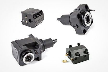
      Turrets & Live Tooling
      • Turrets & Live Tooling
    • Product Image
      Probing
      • Probing
    • Haas Chip & Coolant Management
      Chip & Coolant Management
      • Chip & Coolant Management
    • The Haas Control
      The Haas Control
      • The Haas Control
    • Product Image
      Product Options
      • Product Options
    • Product Image
      Tooling & Fixturing
      • Tooling & Fixturing
    • Product Image
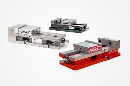
      Workholding
      • Workholding
    • Product Image
      5-Axis Solutions
      • 5-Axis Solutions
      • 5 Easy Steps to 5-Axis
    • Product Image
      Automation
      • Automation
    • QUICK LINKS Special Series  Special Series 
      HAAS CAREERS HAAS CAREERS BUILD & PRICE BUILD & PRICE PRICE LIST PRICE LIST WHAT’S NEW WHAT’S NEW YOUR FIRST CNC YOUR FIRST CNC HAAS SIX PACK HAAS SIX PACK
      SHOPPING TOOLS
      • Build & Price a Haas
      • Price List
      • Available Inventory
      • CNCA Financing
      WANT TO TALK TO SOMEONE?

      A Haas Factory Outlet (HFO) can answer your questions, and walk you through your best options.

      CONTACT YOUR DISTRIBUTOR >
  • Why Haas
      Discover the Haas Difference
      Why Haas MyHaas Education Community Industry 4.0 Haas Certification Customer Testimonials
  • Service
      Welcome to Haas Service
      SERVICE HOME Operator’s Manuals How-To Procedures Troubleshooting Guides Preventive Maintenance Haas Parts Haas Tooling Videos
  • Videos
  • Haas Tooling
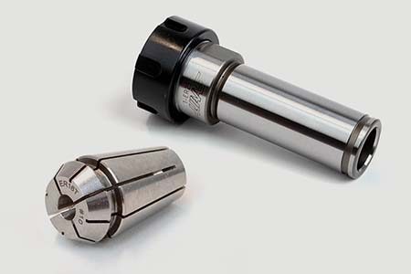
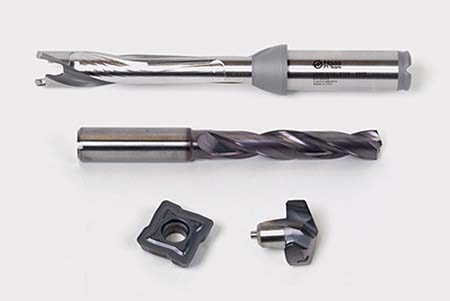
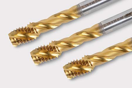
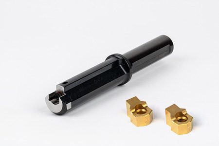
      Haas Tooling Mill Toolholding Mill Workholding Milling Lathe Tooling Lathe Toolholding Lathe Workholding ER Collets & Chucks Holemaking Threading Tool Management Tooling Accessories Package Kits Measuring & Inspection Apparel & Accessories
      HAAS TOOLING QUICK LINKS
      NEW PRODUCTS NEW PRODUCTS
      MOST POPULAR MOST POPULAR
      OPEN TERMS OPEN TERMS
      FINANCING FINANCING
      FAQs FAQs
      KITS CREATED FOR YOU KITS CREATED FOR YOU
  • Haas Service Parts
      Haas Service Parts Automatic Pallet Changer Automatic Tool Changer Chip Management Coolant Counterbalance Electrical Cabinet Enclosure Field Install Options Hydraulics Lubrication Maintenance Pendant Probing Rotary Spindle Tailstock
  • Contact Us

My Cart
MyHaas Welcome,
!
Haas Tooling Guest Order History MyHaas/HaasConnect Sign In Register Haas Tooling My Account Order History Return History MyHaas/HaasConnect Sign Out Welcome, My Machines Latest Activity My Quotes My Account My Users Sign Out
Find A Dealer
  1. Select Language
    1. English
    2. Deutsch
    3. Español
    4. Français
    5. Italiano
    6. Português
    7. Český
    8. Dansk
    9. Nederlands
    10. Magyar
    11. Polski
    12. Svenska
    13. Русский
    14. Türkçe
    15. 中文
    16. Suomi
    17. Norsk
    18. الإنجليزية
    19. български
    20. Hrvatski
    21. Ελληνικά
    22. Română
    23. Slovenský
    24. Slovenščina
    25. 한국어
    26. 日本語
Search
×

Search Results

Web Pages

Images

    • <
    • 1
    • >

18 - NGC - PSUP PCB

Next Gen Control Electrical - Service Manual


  • 1 - NGC - Introduction
  • 2 - NGC - Activation
  • 3 - NGC - Software Update
  • 4 - NGC - Firmware Update
  • 5 - NGC - Configuration and Patch Files
  • 6 - NGC - Error Report and Backup
  • 7 - NGC - Main Processor
  • 8 - NGC - I/O and TC PCB
  • 9 - NGC - CAN Systems and Autodoor
  • 10 - NGC - Servo Motors and Axis Cables
  • 11 - NGC - 4th and 5th Axis
  • 12 - NGC - Servo Amplifiers
  • 13 - NGC - Vector Drive
  • 14 - NGC - Regen
  • 15 - NGC - 320V Power Supply
  • 16 - NGC - Wye / Delta
  • 17 - NGC - Circuit Breaker and Transformer
  • 18 - NGC - PSUP PCB
  • 19 - NGC - SKBIF and LCD Monitor
  • 20 - NGC - Remote Jog Handle
  • 21 - NGC - WorkLights and HIL
  • 22 - NGC - CabCool
  • 23 - NGC - HaasConnect
  • 24 - NGC - Networking
  • 25 - NGC - HaasDrop
  • 26 - NGC - 8M PCB
  • 27 - NGC - Robot and Automation
  • 28 - NGC - Machine Data Collection
  • 29 - NGC - Control Icons
  • 30 - NGC - Sensors and Switches
  • 31 - NGC - USB

Go To :

  • PSUP PCB - Replacement
  • PSUP PCB - Troubleshooting
Recently Updated

PSUP PCB - Replacement - NGC


AD0282

Introduction

This procedure tells you how to replace the PSUP PCB on a machine that has the Next Generation Control.

Prerequisites

Caution: If the machine has a 4075-N and software version lower than 100.16.000.1040 you must install a patch to change Parameter 2009 Before you install the replacement PSUP PCB. Failure to do so will cause the machine to shut down immediately upon power up. If you are replacing a 4075-P or later, no patch is required. Refer to Patch File Load / Uninstall - NGC.

If you install the new PSUP PCB on a machine with software lower than 100.16.000.1040 and did not applied the patch, you must do a clean software installation. Refer to Software Update - (Option 5) Clean Installation - NGC.

This Document Applies to:

  • KIT PN: 93-3412, SVC KIT NGC PSUP-U 3PH CCA

Safety Notes:

Caution: When you do maintenance or repair on CNC machines and their components, you must always follow basic safety precautions. This decreases the risk of injury and mechanical damage.

Do these steps before you do work in the machine or in the control cabinet:

  • Set the main circuit breaker to the [OFF] position.
  • Use an approved lock with an approved safety tag. Always follow lock-out procedures in accordance to local government rules.
  • After turning off the machine, wait at least 5 minutes before working in the control cabinet, to allow power to dissipate. Wait for the voltage indicator LED on the vector drive to go off completely.
  • Always turn off the main air supply when you work on any part of the pneumatic system.
  • Make sure to rest the spindle head on a block of wood when work is done on a vertical axis. This will prevent any unintended movement that could result in the axis falling.
  • Never alter any safety circuits on the machine.
  • Never change any parameter while in [DEBUG] mode (Classic Haas Control) and he servos [ON]. Put the machine in [EMERGENCY STOP] mode to change any parameters.
  • Never operate the machine in [DEBUG] mode (Classic Haas Control).

You should not do machine repair or service procedures unless you are qualified and knowledgeable about the processes. Serious damage to the machine components can result in costly repairs. The service technicians at your Haas Factory Outlet (HFO) have the training and experience, and are certified to do these tasks safely and correctly. The repair and serice work performed by our HFO is protected with a limited warranty.

Danger: Some service procedures can be dangerous or life-threatening. DO NOT attempt a procedure that you do not fully understand. If you have any doubts about doing procedure contact you Haas Factory Outlet (HFO) and schedule a service visit.

PCB Removal

1

Push [POWER OFF].

Set the main circuit breaker to the [OFF] position.

Lock the main circuit breaker. Use an approved lock with an approved safety tag.

Danger: After turning off the machine, wait at least 5 minutes before working in the control cabinet, to allow power to dissipate. Wait for the voltage indicator LED on the vectore drive to go off completely.

Caution: When you handle a PCB, you must wear an Electrostatic Discharge (ESD) strap.

2

If a circuit breaker is at the TSC/HYD pump position on the PSUP PCB, remove it. Keep this breaker to install on the replacement PCB.

Put an identification label  each cable that is attacjed to the PCB. This makes the installation easier. Disconnect these cables.

Remove the standofs.

Remove the PCB.

Installation

1

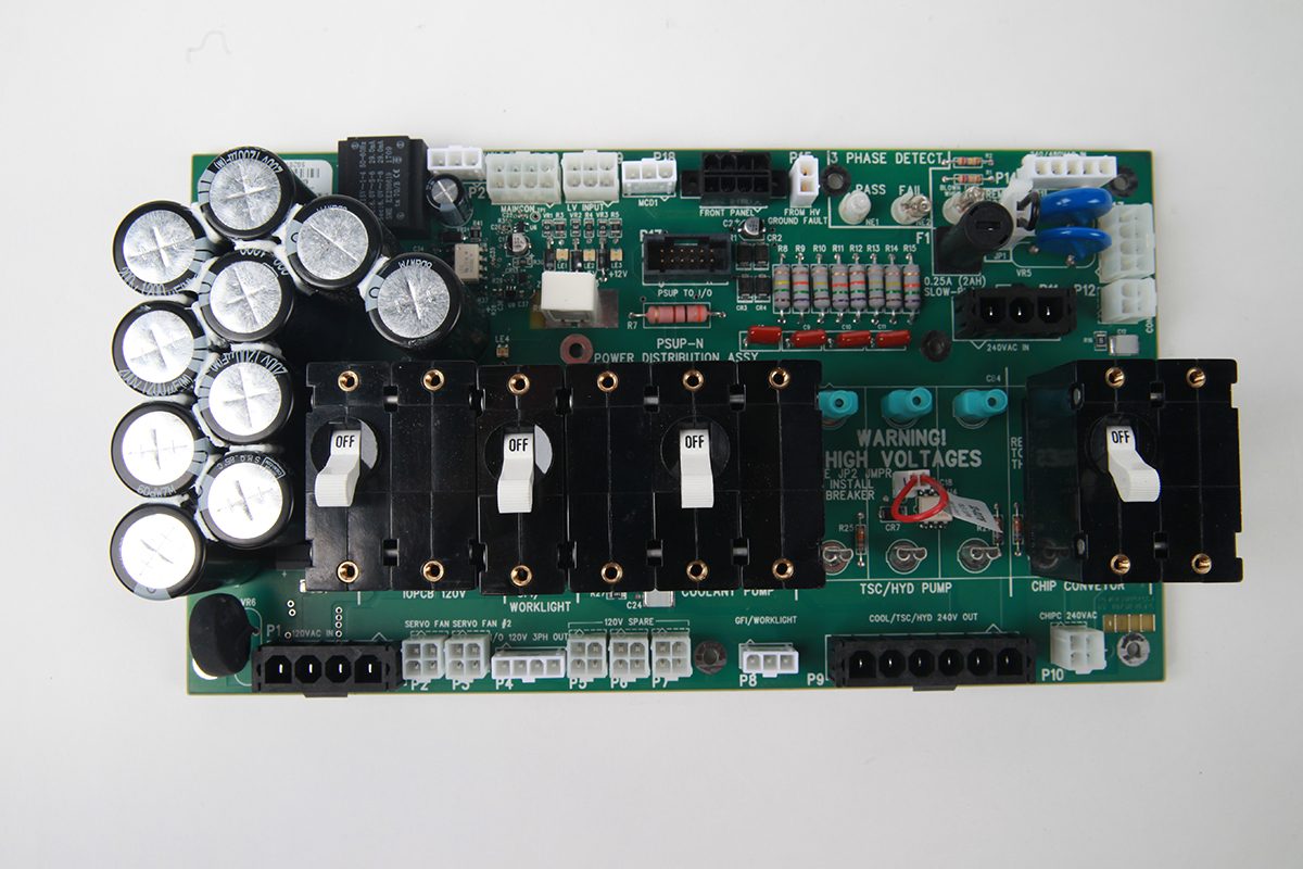
If the machine uses 480V, remove the jumper [1] at JP1 on the PSUP-U 3PH CCA PCB [A].

If the machine has a 60 hp vector drive, install the 2A CERAMIC FUSE [B] at F1.

If the machine uses a circuit breaker for the TSC/HYD pump, do these steps:

  • remove the covers [2] for the connectors.
  • remove the jumper [3] at JP2.
  • install the breaker [4] at the TSC/HYD pump position.

2

Install the replacement PSUP PCB.

Install the standoffs.

Connect all of the cables.

Set all of the circuit breakers on the PSUP PCB to the [ON] position.

[POWER ON] the machine.

3

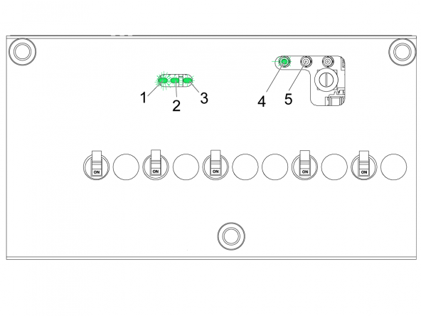
Make sure that LE1 [1], LE2 [2], and LE3 [3] are [ON], and the phase detect-pass lamp [4] is [ON] (green light).

  • Single phase machines
    • The phase-detect-pass lamp [4] must be on
    • The phase-detect-fail lamp [5] must be on
  • Three phase machines
    • The phase-detect-pass lamp [4] must be on
    • The phase-detect-fail lamp [5] must be off

Caution: 3 Phase Machines Only:

If lamps [4] and [5] are [ON]. the system has a loose wire, or a defective power source. 

Make sure that all three phases have power.

If only the phase-detect fail lamp is on, the leads are in the incorrect sequence.

Disconnect the machine from the main power supply and interchange two of the three leads to the machine.

Verification

1

Do these steps to make sure the PSUP PCB operates correctly:

Important: When replacing an older PSUP with Rev P or U make sure the PSUP patch is installed.

To see the installed patches: Turn on the machine with the service key, then go to [PARAMETERS] [PATCHES] tab.  If the patch has not been installed download the patch from the HBC site.

  • Do this test for these circuit breakers:
    • GFCI/Light
    • Coolant pump
    • TSC/HYD pump (if installed)
    • Auger motor

           Caution: Do not do this test for the I/O Board/Fans/Solenoids circuit breaker.

  • Set the switch to the [OFF] position. Alarm 552 , [TRIPPED CIRCUIT BREAKER], occurs.
  • Set the switch to the [ON] position.
  • Push [RESET] to clear each alarm.
Recently Updated

PSUP PCB - Troubleshooting Guide - NGC


Introduction

  • Embeds the Power Fault Detect Module. Now standard on all machines equipped with the Next Generation Control.
  • Indicates the Status of the three phase power.
  • Low Voltage power indicator LEDs.
  • Circuit breaker open indicator circuit.
  • Added a ground fault detect circuit for the 115 VAC line.

Depending on the PSUP version, it may have two or three fuses for different circuits. The universal reference designator for a fuse is “F” or “FU”.

F1 is used to protect the ON/OFF circuit during a power spike or transient.

On PSUP N and newer, F2 is used on the input of the Bridge rectifier for the capacitor bank that is part of the PFDM. This fuse will open if:

1.   The bridge BR1 is shorted.

2.   If any of the alum electrolytic capacitors is shorted

3.   If the LVPS is shorted


Electrical Safety

 Caution: When you do maintenance or repair on CNC machines and their components, you must always follow basic safety precautions. This decreases the risk of injury and mechanical damage.

  • Set the main circuit breaker to the [OFF] position.

 Danger: Before beginning any work inside the control cabinet the High Voltage indicator light on the 320V Power Supply / Vector Drive must have been off for at least 5 minutes.

Some service procedures can be dangerous or life-threatening. DO NOT attempt a procedure that you do not fully understand. If you have any doubts about doing a procedure contact your Haas Factory Outlet (HFO) and schedule a service visit.

Symptom Table

Symptom / Alarm Possible Cause Corrective Action
Alarm 552 TRIPPED CIRCUIT BREAKER There is an current overload or short-circuit detected at the power distribution PCB. One or more circuit breakers is not installed correctly. Check the Power Distribution PCB. Make sure the circuit breakers are properly seated.
The TSC jumper JP2 is missing. On machines without TSC/HPC circuit breaker jumper JP2 must be installed.
A short-circuit detected on CB3 coolant pump breaker, CB3 tripped.
  1. Check 240VAC cable from PSUP (P9) to I/O PCB (P30). Make sure that cable is not pinched. Make sure that cabled is wired correctly.
  2. Check the 240VAC cable from I/O (P29) to coolant pump amphenol. Make sure the cable is not pinched. Make sure that cable is wired correctly.
  3. Disconnect the connector from I/O PCB (P29) and check red and black wire to ground they should read open (O.L).
  4. Check for short-circuit on coolant pump/cable. Refer to the: Standard Coolant - System - Troubleshooting Guide
(Single-phase machines only), Alarm 552 TRIPPED CIRCUIT BREAKER occurs when the coolant pump gets commanded to turn on.

Note: The circuit breaker did not trip.

The 240 VAC input cable connected to the PSUP at P11 is not correct. Turn off the main breaker and disconnect 240 VAC input cable from the PSUP at P11 and swap the white and black wire positions on the cable.
Alarm 9101 RESETTABLE SOFTWARE ERROR One or more circuit breakers is turned OFF. Check the Power Distribution PCB. Find the cause of the short-circuit then turn the circuit breaker back on.

Alarm 175 GROUND FAULT DETECTED 

Alarm 9803 120VAC GROUND FAULT

Alarm 9804 240 VAC GROUND FAULT

There is a short circuit in one of the 115 / 230 VAC components. Spindle motor/cable and Axis motors/cables as well. Refer to the Next Generation Control - I/O PCB - Troubleshooting Guide.
Alarm 9902 GROUND FAULT One of the PSUP circuit breakers is not installed correctly. Check all the circuit breakers tabs to make sure they are installed inside the female tabs.

Alarm 840 INCOMING AC LINE VOLTAGE TOO LOW DURING POWER UP

or the AC Line Voltage gauge is not showing the correct reading.
There is a problem with the incoming voltage.  Check the incoming voltage and make sure the transformer taps are in the correct location. 
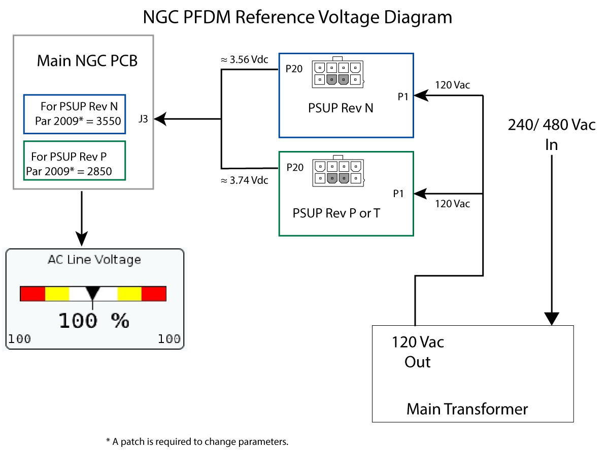
The voltage monitor circuit on the power card PCB is not outputting the correct reference voltage. Make sure the PFDM on PSUP PCB is putting the correct reference voltage to NGC Main PCB.
The Power Card was replaced with a REV - P but the patch file was not installed or the software upgraded. If the machine has a 4075-N and software version lower than 100.16.000.1040 you must install a patch to change parameter 2009 before you install the replacement PSUP PCB. Failure to do so will cause then machine to shut down immediately upon power up.

If you are replacing a 4075-P with a 4075-P no patch is required.

Refer to: Next Generation Control - Patch File Load/Uninstall

If you install the 4075-P or 4075-T on a machine with software lower than 100.16.000.1040 and did not applied the patch, you must do a clean software installation. Refer to

Next Generation Control - Software Download and Update - Clean Installation

Alarm 840 INCOMING AC LINE VOLTAGE TOO LOW DURING POWER UP

Alarm continues to appear after replacing the PSUP PCB with 4075- REV - P.
There is a defective component on the PSUP PCB - REV - P. Contact the service department for troubleshooting information.
The machine will not turn on. The F1 fuse is blown. Check F1 fuse, check the JP1 jumper to be installed if the machine has a High Voltage service input (380-480 VAC).
There is problem with the power on/off circuit. Refer to: Next Generation Control - Power On/Off Circuit, Main Transformer - Troubleshooting Guide.

Power Fault Detect Module (PFDM) Reference Voltage

There is an embedded power fault detect monitor built-in to the NGC power card PCB. The circuit monitors the 115VAC output of the main transformer (TB 94, 95). This circuit produces a 0 - 5 VDC reference voltage to the main NGC PCB. This reference voltage varies in proportional to the incoming AC voltage. The variance in this voltage will cause the AC Line Voltage gauge to change. When the output of the transformer equals 120 VAC the control will show 100% AC LINE VOLTAGE. This gauge is located under DIAGNOSTIC / GAUGES. 

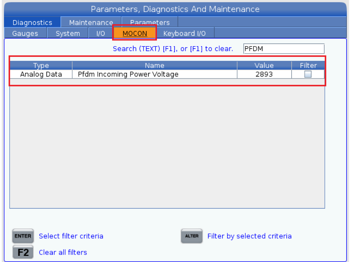
 Note: The data signal input from the PFDM can be viewed under the MOCON Tab listed as Pfdm Incoming Power Voltage.

Corrective Action:

  1. Measure the incoming AC voltage to the machine.
  2. Make sure the transformer taps are in the correct voltage range.
  3. Make sure the 115 VAC output cable from the transformer terminal block 94, 95 is properly connected to the power card at P1.

     Note: When the 115 VAC output of the transformer equals 120VAC the control will show 100% AC LINE VOLTAGE.

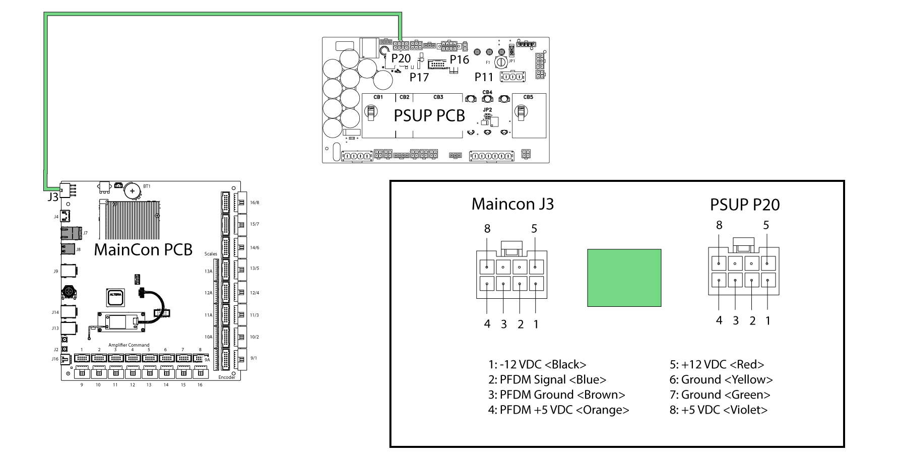
  4. Measure the brown and the blue wire on the PSUP PCB behind the P20 connector (see illustration) .

     Caution: Make sure you use needle tip leads on your meter. Be careful not to short your leads together this can cause damage to the NGC power PCB.

    You should measure approximately:
    • For a Rev -N Power Card 3.56 VDC.
    • For a Rev -P or -T Power Card 3.74 VDC.
    If low or no voltage is measured, the voltage monitor circuit on the power card is damaged and will need to be replaced.

    If the voltage is correct:

    • For a Rev -N Power Card make sure parameter 2009 ADC VALUE FOR AC INPUT is set to 3550.
    • For a Rev -P or -T Power Card make sure parameter 2009 ADC VALUE FOR AC INPUT is set to 2850.

     Note: To view the parameter values refer to Next Generation Control - How to Read an Error Report for more information.


    If the value of parameter of 2009 is not correct you will need to load a patch file. Go to the HBC site and click on Service>NGC-Configuration, and download the patch.

Low Voltage Inspection

Corrective Action:

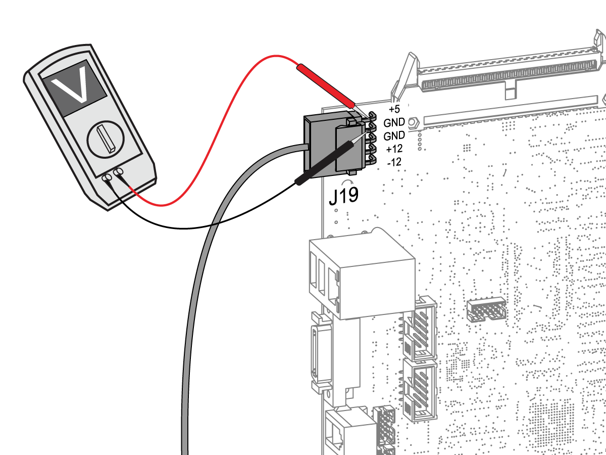
Measure the low voltage power supply voltage levels at the Maincon PCB. Make sure you do not short or cross your multimeter pins.

Cycle power to the machine. If the fault stays, then the amplifier is faulty.

If every axis amplifier in the machine generates the alarm at the same time, and the low voltage power supply is correct, then the Maincon PCB may be at fault.

Pins Correct Voltage
+5 and GND +4.90 to +5.20 V dc
+12 and GND +11.85 to +12.50 V dc
-12 and GND -11.85 to -12.50 V dc

PCB Component Inspection

Intermittent symptoms or alarms can be caused by component failure. Below is a list of possible failures:

  1. Missing solder on all or some components pins
  2. Poor solder
  3. Solder bridges
  4. Wrong component installation (orientation)
  5. Missing components

     Note: Some PCB's have unused circuits and are missing components intentionally, look for broken off components.

  6. Broken components
  7. Broken pins on IC's
  8. Bent pins on the connectors
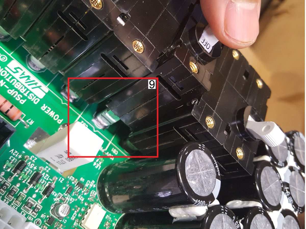
  9. Circuit breakers not installed correctly.

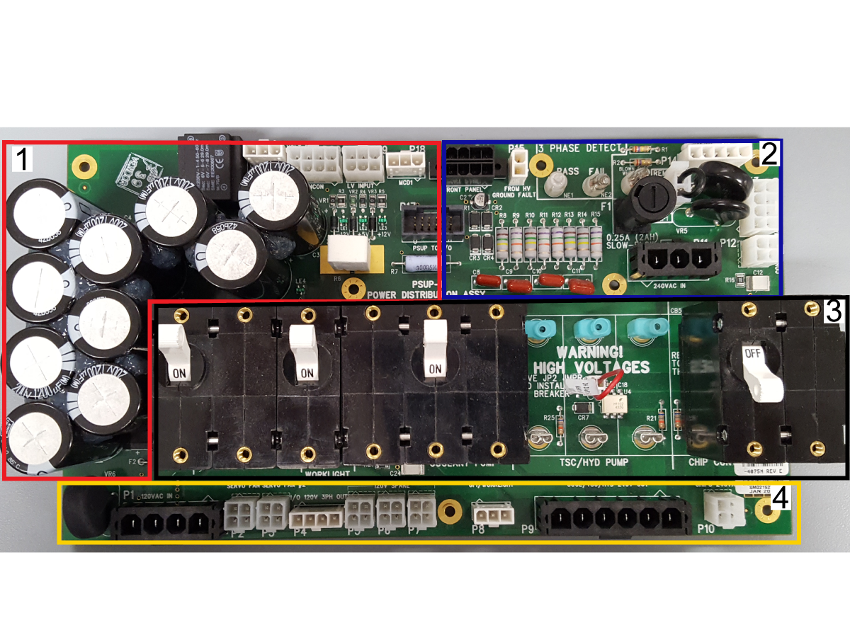
Use a magnifying glass to inspect the circuit components on the front and back of the PSUP PCB. Below are the circuit component zones to inspect depending on the alarm or symptom:

  1. Power Fault Detect Module circuit components, look for leaky capacitors, damaged components.
  2. Ground fault monitor circuit, inspect surface mount components, resistors and bent pins on the connectors.
  3. Circuit breaker trip circuit, pull breakers and inspect for burnt components underneath the breakers.
  4. Inspect for bent or missing pins on the connectors.
  5. Inspect all solder joints and surface mount components on the back of the PSUP PCB.

 Important: If you find a damaged component, replace the PSUP PCB, inspect the new PSUP PCB circuit components before installing.

Electrical Diagrams

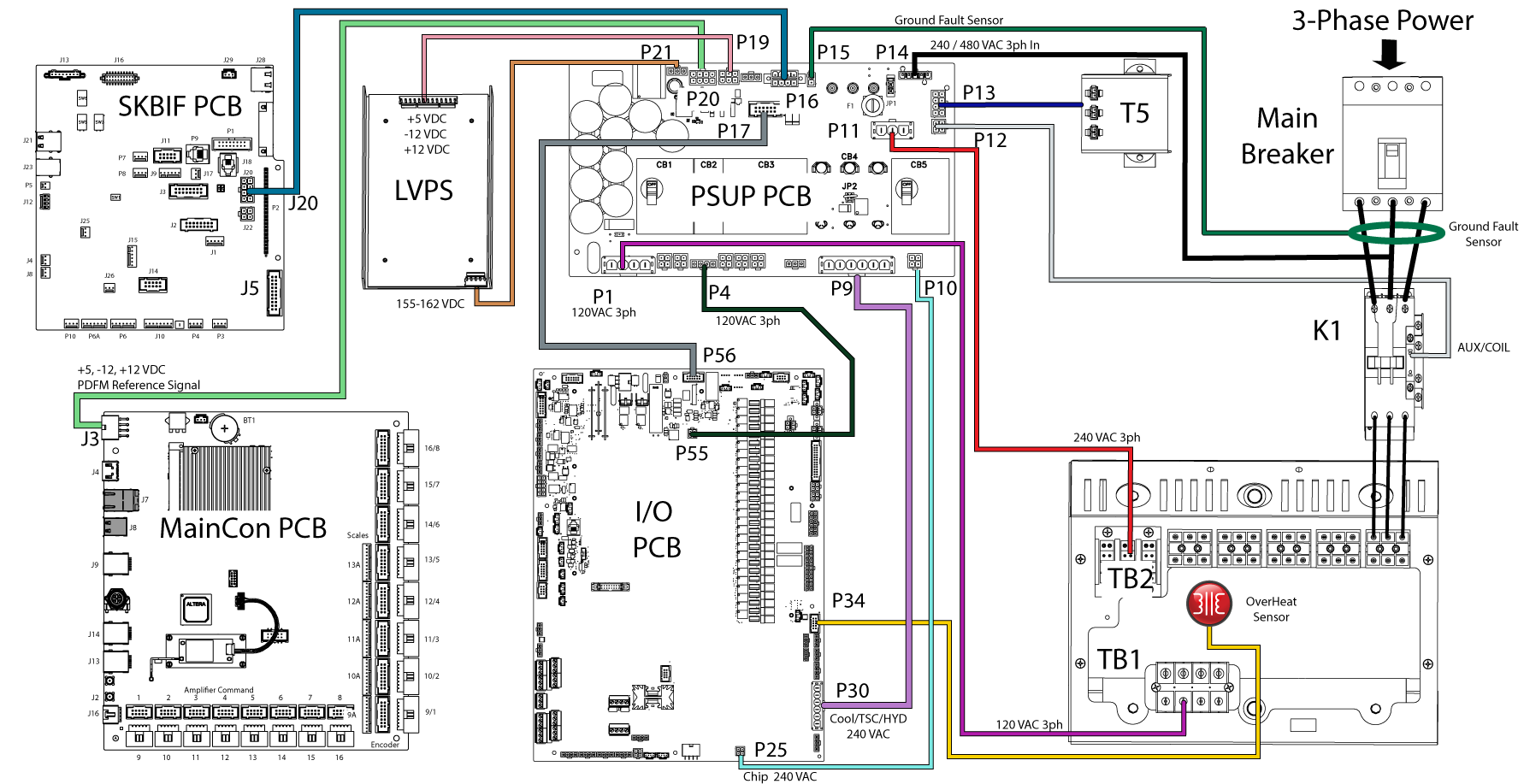
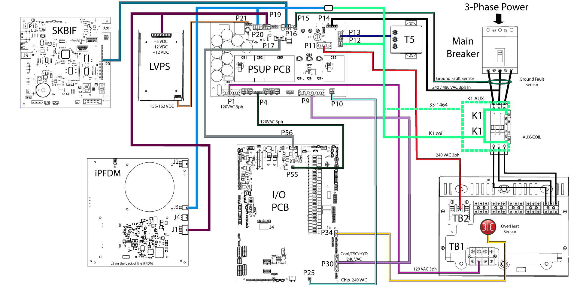
PSUP Interconnect Diagram

PSUP (P17) to I/O PCB (P56) Detail Diagram

Maincon PCB (J3) to PSUP PCB (P20) Detail Diagram

FIND DISTRIBUTOR
Feedback
Haas Logo

美元价格不包括关税、报关费用、保险费、增值税及运费。
USD prices DO NOT include customs duty, customs fees, insurance, VAT, or freight.

人民币价格包含关税、报关费用、货运保险和增值税, 但不包括运费。
CNY prices include customs duty, customs fees, insurance, and VAT. DOES NOT include freight.

Haas Delivered Price

This price includes shipping cost, export and import duties, insurance, and any other expenses incurred during shipping to a location in France agreed with you as a buyer. No other mandatory costs can be added to the delivery of a Haas CNC Product.

KEEP UP WITH THE LATEST HAAS TIPS AND TECHNOLOGY...

Sign up now!   

HAAS TOOLING ACCEPTS THE FOLLOWING:

  • Service & Support
  • Owners
  • Request Service
  • Operator Manuals
  • Haas Parts
  • Rotary Repair Request
  • Pre-Install Guides
  • Shopping Tools
  • Build & Price a New Haas
  • Available Inventory
  • The Haas Price List
  • CNCA Financing
  • About Haas
  • Careers
  • Certifications & Safety
  • Contact Us
  • History
  • Terms & Conditions
  • Haas Tooling Terms & Conditions
  • Privacy
  • Warranty
  • Haas Community
  • Haas Certification Program
  • Haas Motorsports
  • Gene Haas Foundation
  • Haas Technical Education Community
  • Events
  • Join the Conversation
  • Facebook
  • Twitter
  • Flickr
  • YouTube
  • LinkedIn
  • Instagram
  • TikTok
© 2022 Haas Automation, Inc – CNC Machine Tools

2800 Sturgis Rd., Oxnard, CA 93030 / Toll Free: 800-331-6746
Phone: 805-278-1800 / Fax: 805-278-2255

Cookie Notice

We use cookies to improve your user experience. Our Cookie Notice describes which cookies we use, why we use them, and how you can find more information about them. Please confirm you consent to us using analytics cookies. If you do not consent, you may still use our website with a reduced user experience.

Manage Settings

Cookie Notice

We use cookies to improve your user experience. Our Cookie Notice describes which cookies we use, why we use them, and how you can find more information about them. Please confirm you consent to us using analytics cookies. If you do not consent, you may still use our website with a reduced user experience.

Functional Cookies

Analytics Cookies