My Haas Welcome,
!
Haas Tooling MyHaas/HaasConnect Sign In Register Haas Tooling MyHaas/HaasConnect Sign Out Welcome, My Machines Latest Activity My Quotes My Account My Users Sign Out
Find Your Distributor
  1. Select Language
    1. English
    2. Deutsch
    3. Español - ES
    4. Español - MX
    5. Français
    6. Italiano
    7. Português
    8. Český
    9. Dansk
    10. Nederlands
    11. Magyar
    12. Polski
    13. Svenska
    14. Türkçe
    15. 中文
    16. Suomi
    17. Norsk
    18. الإنجليزية
    19. български
    20. Hrvatski
    21. Ελληνικά
    22. Română
    23. Slovenský
    24. Slovenščina
    25. 한국어
    26. 日本語
    27. Українська
  • machines Main Menu
    • Vertical Mills
      Vertical Mills
      Vertical Mills View All
      • Vertical Mills
      • VF Series
      • Universal Machines
      • VR Series
      • VP-5 Prismatic
      • Pallet-Changing VMCs
      • Mini Mills
      • Mold Machines
      • High-Speed Drill Centers
      • Drill/Tap/ Mill Series
      • Toolroom Mills
      • Pocket Mill
      • Compact Mills
      • Gantry Series
      • SR Sheet Routers
      • Extra-Large VMC
      • Double-Column Mills
      • 3+2 Positioning Machines
    • Multi-Axis Solutions
      Multi-Axis Solutions
      Multi-Axis Solutions View All
      • Multi-Axis Solutions
      • Y-Axis Lathes
      • 5-Axis Mills
    • Lathes
      Lathes
      Lathes View All
      • Lathes
      • ST Series
      • Dual-Spindle
      • Box Way Series
      • Toolroom Lathes
      • Chucker Lathe
      • Pocket Lathe
      • Haas Bar Feeders
    • Horizontal Mills
      Horizontal Mills
      Horizontal Mills View All
      • Horizontal Mills
      • 50-Taper
      • 40-Taper
    • Rotaries & Indexers
      Rotaries & Indexers
      Rotaries & Indexers View All
      • Rotaries & Indexers
      • Rotary Tables
      • Indexers
      • 5-Axis Rotaries
      • Extra-Large Rotaries
    • Special Series
      Special Series
      Special Series View All
      • Special Series
      • EU_Series_Redirect
    • Automation Systems
      Automation Systems
      Automation Systems View All
      • Automation Systems
      • Mill Automation
      • Lathe Automation
      • Automatic Parts Loaders
      • Automation Models
    • Desktop Machines
      Desktop Machines
      Desktop Machines View All
      • Desktop Machines
      • Desktop Mill
      • Desktop Lathe
      • Control Simulator, Standard
      • Control Simulator, Premium
    • Shop Equipment
      Shop Equipment
      Shop Equipment View All
      • Shop Equipment
      • Knee Mill
      • Haas Manual Lathes
      • Haas Saws
    • Fabrication Machines
      Fabrication Machines
      Fabrication Machines View All
      • Fabrication Machines
      • Laser Cutting Machines
      • CNC Press Brakes
    • QUICK LINKS Special Series  Special Series 
      EU SERIES EU SERIES BUILD & PRICE | PRICE LIST BUILD & PRICE | PRICE LIST In-Stock Machines In-Stock Machines WHAT’S NEW WHAT’S NEW YOUR FIRST CNC YOUR FIRST CNC
      SHOPPING TOOLS
      • Build & Price a Haas
      • Price List
      • Available Inventory
      • CNCA Financing
      WANT TO TALK TO SOMEONE?

      A Haas Factory Outlet (HFO) can answer your questions, and walk you through your best options.

      CONTACT YOUR DISTRIBUTOR >
  • Options Main Menu
    • The Haas Control Value Option Packages
      Value Option Packages
      Value Option Packages View All
      • Value Option Packages
    • Product Image Spindles
      Spindles
      Spindles View All
      • Spindles
    • Product Image Tool Changers
      Tool Changers
      Tool Changers View All
      • Tool Changers
    • Product Image 4th- | 5th-Axis
      4th- | 5th-Axis
      4th- | 5th-Axis View All
      • 4th- | 5th-Axis
    • Product Image Turrets & Live Tooling
      Turrets & Live Tooling
      Turrets & Live Tooling View All
      • Turrets & Live Tooling
    • Product Image Probing
      Probing
      Probing View All
      • Probing
    • Haas Chip & Coolant Management Chip & Coolant Management
      Chip & Coolant Management
      Chip & Coolant Management View All
      • Chip & Coolant Management
    • The Haas Control The Haas Control
      The Haas Control
      The Haas Control View All
      • The Haas Control
    • Product Image Product Options
      Product Options
      Product Options View All
      • Product Options
    • Product Image Tooling & Fixturing
      Tooling & Fixturing
      Tooling & Fixturing View All
      • Tooling & Fixturing
    • Product Image Workholding
      Workholding
      Workholding View All
      • Workholding
    • Product Image 5-Axis Solutions
      5-Axis Solutions
      5-Axis Solutions View All
      • 5-Axis Solutions
      • 5 Easy Steps to 5-Axis
    • QUICK LINKS Special Series  Special Series 
      EU SERIES EU SERIES BUILD & PRICE | PRICE LIST BUILD & PRICE | PRICE LIST In-Stock Machines In-Stock Machines WHAT’S NEW WHAT’S NEW YOUR FIRST CNC YOUR FIRST CNC
      SHOPPING TOOLS
      • Build & Price a Haas
      • Price List
      • Available Inventory
      • CNCA Financing
      WANT TO TALK TO SOMEONE?

      A Haas Factory Outlet (HFO) can answer your questions, and walk you through your best options.

      CONTACT YOUR DISTRIBUTOR >
  • Why Haas Main Menu
      Discover the Haas Difference
    • Why Haas
    • MyHaas
    • Education Community
    • Industry 4.0
    • Haas Certification
    • Customer Testimonials
  • Service Main Menu
      Welcome to Haas Service
      SERVICE HOME Operator’s Manuals How-To Procedures Troubleshooting Guides Preventive Maintenance Haas Parts Haas Tooling Videos
  • Videos Main Menu
  • Main Menu
    • View All
    • View All
    • View All
    • View All
      • HTEC Curriculum Support
      • Haas Value Option Packages (VOP) Journey
    • View All
      • Haas 10 kg Cobot Package
      • Cobot Kits
      • DC-1 Drill Center
      • CNC Sales News
      • Do More With Your Haas
    • View All
    • View All
      • contact-us-test
      • 4 - AUTOMATION SYSTEMS
      • Carousel-V2
      • expert test
      • Demo_Day_Trident-test
      • Link Test
      • image-sale-tag-test
      • article-list-test
      • Haas 25 kg Robot Package
      • test-algolia-page
    • View All
    • View All
    • View All
    • View All
      • calc-test
    • View All
    • QUICK LINKS Special Series  Special Series 
      EU SERIES EU SERIES BUILD & PRICE | PRICE LIST BUILD & PRICE | PRICE LIST In-Stock Machines In-Stock Machines WHAT’S NEW WHAT’S NEW YOUR FIRST CNC YOUR FIRST CNC
      SHOPPING TOOLS
      • Build & Price a Haas
      • Price List
      • Available Inventory
      • CNCA Financing
      WANT TO TALK TO SOMEONE?

      A Haas Factory Outlet (HFO) can answer your questions, and walk you through your best options.

      CONTACT YOUR DISTRIBUTOR >
  • Haas Tooling Main Menu
  • Haas Service Parts Main Menu

My Haas Welcome,
!
Haas Tooling MyHaas/HaasConnect Sign In Register Haas Tooling MyHaas/HaasConnect Sign Out Welcome, My Machines Latest Activity My Quotes My Account My Users Sign Out
Find Your Distributor
  1. Select Language
    1. English
    2. Deutsch
    3. Español - ES
    4. Español - MX
    5. Français
    6. Italiano
    7. Português
    8. Český
    9. Dansk
    10. Nederlands
    11. Magyar
    12. Polski
    13. Svenska
    14. Türkçe
    15. 中文
    16. Suomi
    17. Norsk
    18. الإنجليزية
    19. български
    20. Hrvatski
    21. Ελληνικά
    22. Română
    23. Slovenský
    24. Slovenščina
    25. 한국어
    26. 日本語
    27. Українська
×

Search Results

Web Pages

Images

    • <
    • 1
    • >

17 - NGC - Circuit Breaker and Transformer

Next Gen Control Electrical - Service Manual


  • 1 - NGC - Introduction
  • 2 - NGC - Activation
  • 3 - NGC - Software Update
  • 4 - NGC - Firmware Update
  • 5 - NGC - Configuration
  • 6 - NGC - Error Report and Backup
  • 7 - NGC - Main Processor
  • 8 - NGC - I/O and TC PCB
  • 9 - NGC - CAN Systems and Autodoor
  • 10 - NGC - Servo Motors and Axis Cables
  • 11 - NGC - 4th and 5th Axis
  • 12 - NGC - Servo Amplifiers
  • 13 - NGC - Vector Drive
  • 14 - NGC - Regen
  • 15 - NGC - 320V Power Supply
  • 16 - NGC - Wye / Delta
  • 17 - NGC - Circuit Breaker and Transformer
  • 18 - NGC - PSUP PCB
  • 19 - NGC - SKBIF and LCD Monitor
  • 20 - NGC - Remote Jog Handle
  • 21 - NGC - 115V LED - WorkLights
  • 22 - NGC - CabCool
  • 23 - NGC - MyHaas
  • 24 - NGC - Networking
  • 25 - NGC - 8M PCB
  • 26 - NGC - Robot and Automation
  • 27 - NGC - Machine Data Collection
  • 28 - NGC - Control Icons
  • 29 - NGC - Sensors and Switches
  • 30 - NGC - USB
  • 31 - NGC - Keypad
  • 32 - NGC - Broken Tool Detection
  • 33 - NGC - IPFDM PCB
  • 34. NGC - LVPS
  • 35 - NGC - Camera Monitor System
  • 36 - NGC - High Intensity Lights
  • 37 - NGC - 24V LED - Worklights
  • 38 - NGC - Mill - Rotary Scale Cable Installation

Go To :

  • 17.1 Main Circuit Breaker - Replacement
  • 17.2 Main Transformer - Replacement
  • 17.3 Main Transformer - Troubleshooting
  • 17.4 Circuit Breaker - Troubleshooting

17.1 Main Circuit Breaker - Replacement

Recently Updated

Main Circuit Breaker - Replacement


AD0286

Introduction

This procedure tells you how to replace the main circuit breaker in the electrical cabinet. The circuit breaker in the kit can be different from the installed circuit breaker, but it operates the same.

Document Applies to these Parts
Kit Required: CIRCUIT BREAKER REPLACEMENT KIT

Breaker Amperage 15A 20A 40A 80A 125A
Kit P/N 93-2550 93-2551 93-2552 93-2553 93-2554

Main Circuit Breaker - Replacement

1

Push [POWER OFF].

 Danger: Disconnect the electrical service to the machine.

 Important: With and AC Volt meter, measure across the L1 - L3 on top of the main breaker. If AC voltage is still present go to the source and check that the correct service breaker was disconnected.

 Danger: After you disconnect the service to the machine, wait for the LEDs on the early power-fault detection module (EPFDM) and the vector drive to go off fully. This may take 20 or more minutes.

2

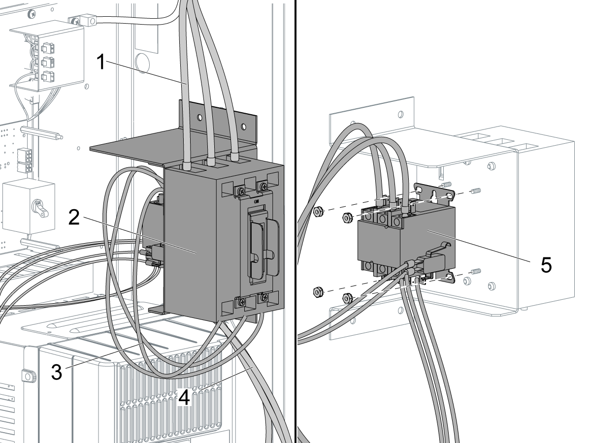
Record the color sequence of the main electrical supply wires [1] that go to the circuit breaker [2]. Disconnect the wires.

Disconnect the contactor cables [3] from the circuit breaker.

If the contactor [5] is installed on the rear of the circuit breaker, disconnect the (3) transformer cables [4] at the transformer.

Remove the circuit breaker assembly [2] from the machine.

Remove the circuit breaker from the breaker mount bracket.

Discard the circuit breaker if it is not under warranty.

3

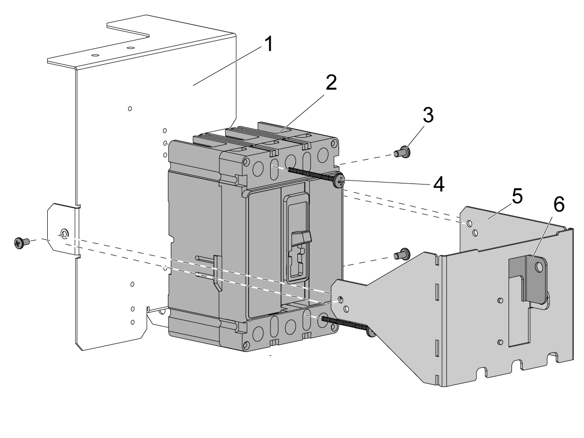
Use (2) long screws [4] to attach the new circuit breaker [2] to the breaker mount bracket [1].

Select the holes on the bracket that allow the switch on the circuit breaker to fit through the hole on the locking bracket [5].

Use (3) short screws [3] to attach the locking bracket [5] to the breaker mount bracket [1].

Select the holes on the locking bracket that allow the toggle [6] to move freely.

 Note: The circuit breaker you receive may look different from the one illustrated. Assembly is the same.

4

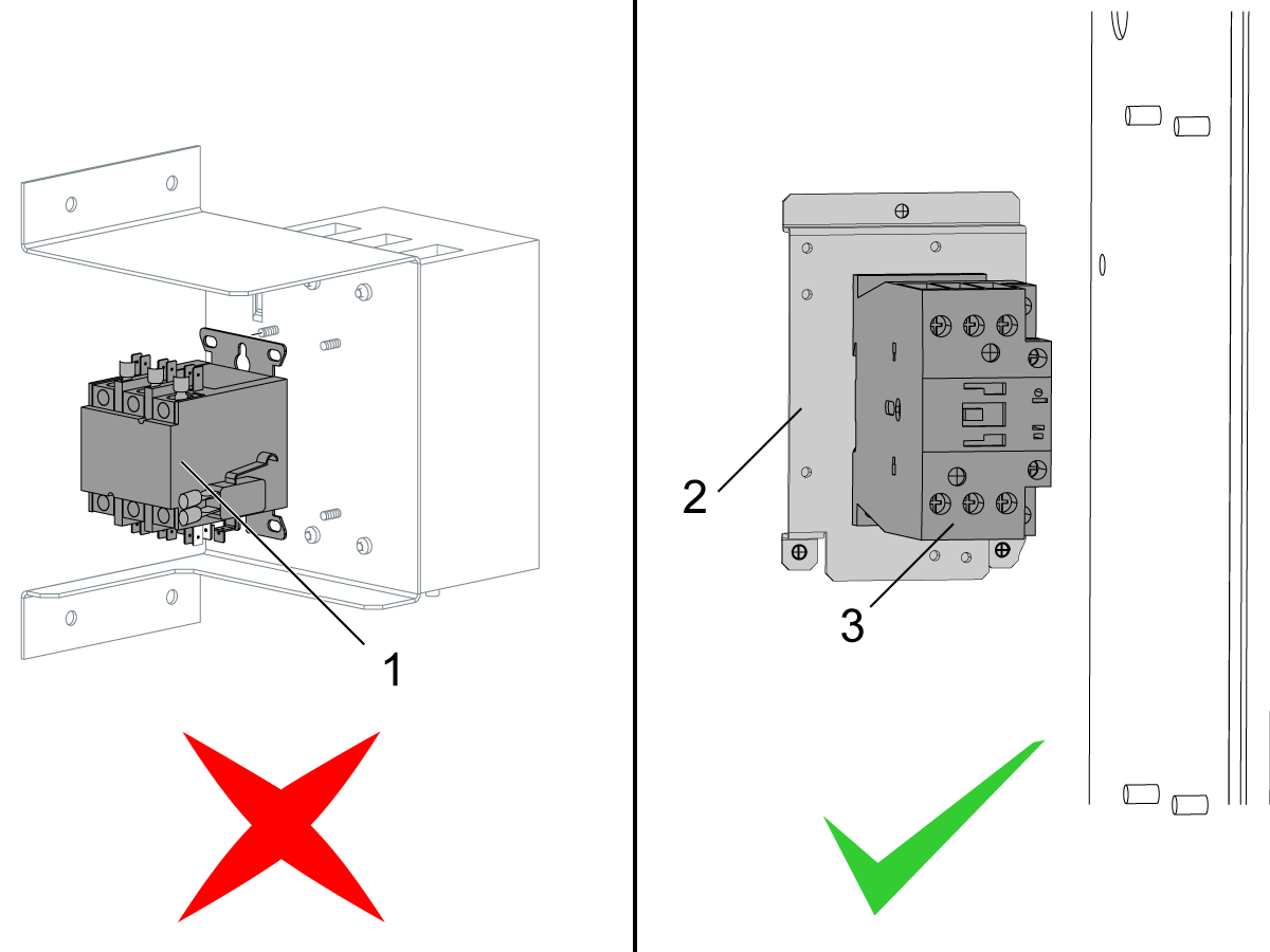
Do this step only if the contactor was installed on the rear of the used circuit breaker assembly.

  • Install the the contactor adapter bracket P/N 25-12101 [2] to the back wall of the cabinet.
  • Install the contactor [3] included in the kit to the adapter bracket.
  • Connect the cables going to the contactor.

5

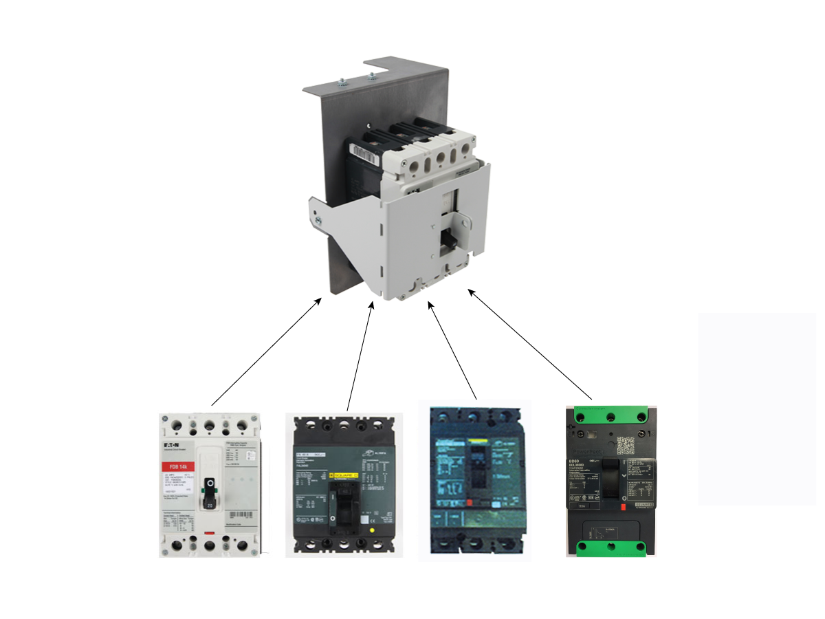
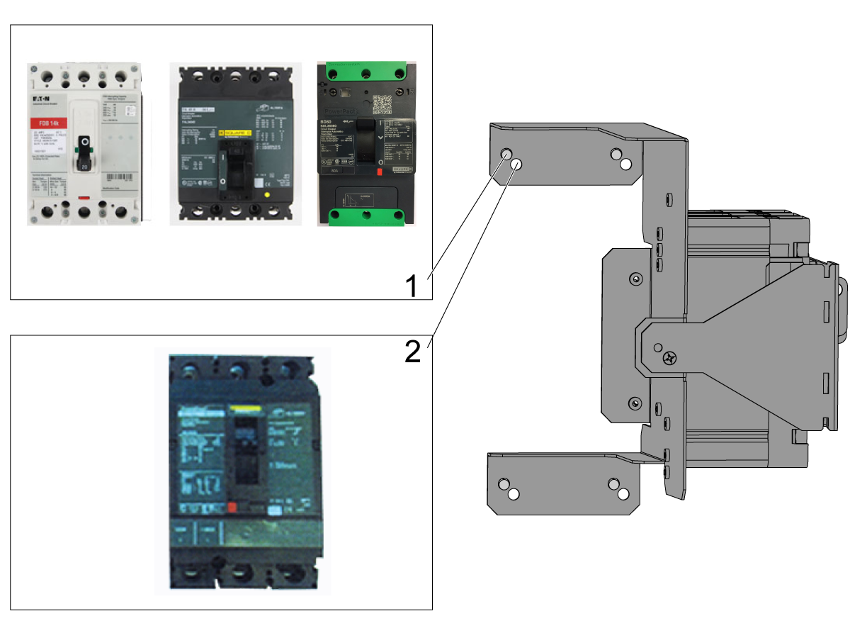
The bracket for the circuit breaker assembly has (2) sets of holes to attach it to the electrical cabinet.

Look at the circuit breaker.

  • If the circuit breaker is the same as a breaker in the first group [1], use the top set of holes.
  • If the circuit breaker is the same as a breaker in the second group [2], use the bottom set of holes.

Attach the circuit breaker assembly to the electrical cabinet.

Install the main breaker cover. Refer to Main Breaker Cover Installation procedure included in the kit.

Connect the cables. Refer to Haas Main CIrcuit Breaker - Torque Specifications for what value to torque the circuit breaker power leads.

Turn on the electrical service to the machine, and test for correct operation and phasing.

17.2 Main Transformer - Replacement

Recently Updated

Main Transformer - Replacement


AD0408

Replacement

This section applies to all size main transformer replacements and machine models.

1

Turn off the main breaker and lock out the machine from use. Verify there is no power going to the transformer with a volt meter.

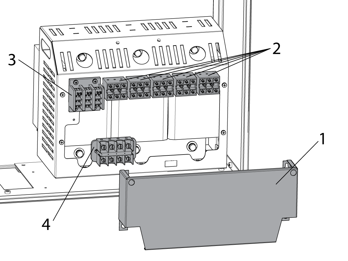
Loosen the (4) screws and remove the cover plate [1].

NOTE: Before removing the transformer wires take couple pictures of where cables are connected.

Label and disconnect the wires from the appropriate taps [2], TB2 the 240 VAC terminal block [3], and TB1 the 120 VAC terminal block [4].

2

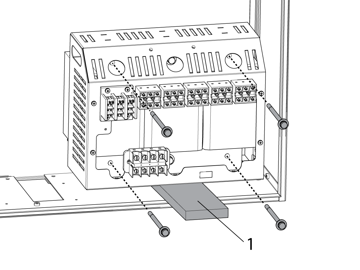
Insert a piece of wood [1] (1"X4" approx.) to support the transformer. Remove the (4) corner bolts only and remove the transformer.

Install the replacement transformer in the reverse order it was removed. 

Important: If the transformer comes with its own hardware, you must use it. Do not reuse hardware

3

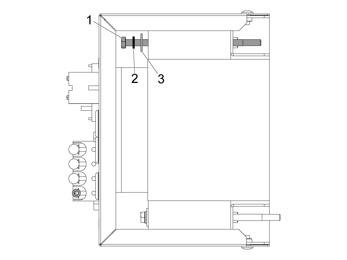
Install the hardware shown in the image.

  1. Hex Head Bolt
  2. Lock Washer
  3. Black Oxide Hard Washer

Apply blue loc-tite and torque the (4) bolts to 15 ft-1b (20 Nm).

NOTE:  Do not over torque the bolts as it will cause the back plate to warp.

Thermal Sensor

The following section applies to only the transformers that are equipped with a thermal sensor (see table below).  

Transformers with a Thermal Sensor
32-5800H 32-5810K 32-5811C
32-5814B 32-5822D 32-5825F
32-5826 32-5829 32-5830A
32-5831A 32-5832A 32-5833B
32-5834B 32-5835B 32-5836
32-5837 32-5830E  

For Coldfire Control: 

  • Plug the thermal sensor to I/O PCB at P82.
  • Change parameter 1397 TRANSFORMER OVER HEAT MAX TIME to 60000.  A value of zero will disable this feature.
     Note: If the machine software does not have parameter 1397 TRANSFORMER OVER HEAT MAX TIME available, tuck the overheat cable inside the wire track.

For Next Generation Control:

  • Plug the thermal sensor I/O at P34.
  • Upload a new configuration file. The configuration file is updated when the part is ordered.

17.3 Power On/Off Circuit - Main Transformer - Troubleshooting Guide

Recently Updated

Power On/Off Circuit - Main Transformer - Troubleshooting Guide - NGC


TG0004

Introduction

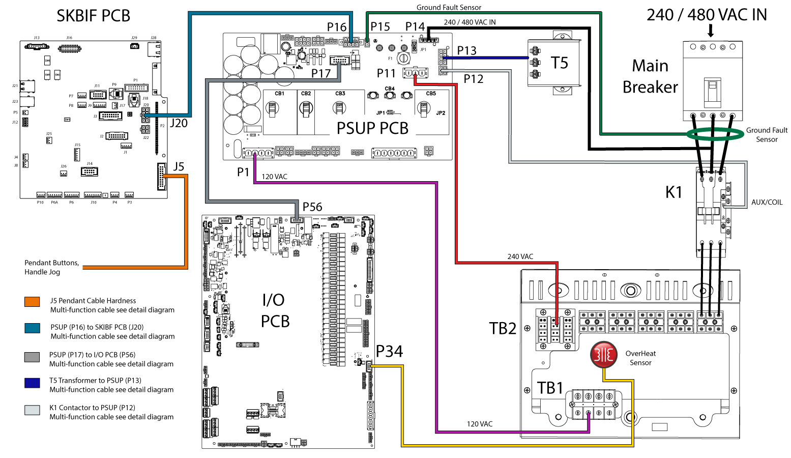
This document will show you how to troubleshoot the power on/off circuit and the main transformer on a machine with the Next Generation Control.

Electrical Safety

 DANGER: Working with the electrical services required for CNC machines is extremely hazardous and can result in serious injury or death.

Before connecting line wires to the CNC:

  • Turn off all power to the machine at the source.
  • Perform a Lockout-Tagout (LOTO) procedure to ensure the power remains off during service.
  • Verify that power has been disconnected by using an AC voltage detector on all incoming lines.

If you are uncertain about how to safely disconnect power or perform LOTO procedures:

  • Do not proceed.
  • Contact qualified personnel or obtain appropriate assistance before continuing.

Failure to follow these precautions may result in electrical shock, equipment damage, or fatal injury.

 Danger: Before beginning any work inside the control cabinet, verify that the High Voltage indicator light on the 320V Power Supply / Vector Drive has been off for a minimum of five (5) minutes. This waiting period ensures that residual voltage has dissipated and reduces the risk of electric shock.

Certain service procedures involve high-risk electrical components and may pose serious injury or fatality hazards. Technicians must not attempt any procedure unless they have a complete understanding of the steps involved and the associated risks.

If there is any uncertainty regarding a procedure, contact your Haas Factory Outlet (HFO) to arrange for a qualified service technician.

Power On/Off Circuit

Electrical Wiring for Haas Machines

Symptom Table

Symptoms Probable Cause Corrective Action
Alarm 2095 TRANSFORMER OVERHEAT occurs at Power on. The machine detected a open circuit from the thermal switch at the transformer. Make sure the sensor is connected to the pigtail on P34 on I/O PCB. If is connected, jumper the wires. If alarm goes away check the overheat sensor by measuring the temperature on the transformer the sensor is normally closed until trip point 275F / 135C.
The transformer overheat cable pins making intermittent contact. Check the connector to make sure the connector is crimped correctly.
Alarm 2095 TRANSFORMER OVERHEAT occurs after the machine has been on for a long time, or during operation. The speeds and feeds are too high. Make sure the feeds and speeds are correct for the work.
The transformer overheat cable pins making intermittent contact. Check the connector to make sure the connector is crimped correctly.
The machine is located in a hot environment. Monitor the transformer temperature throughout the day. If the internal transformer exceeds 275F / 135C degrees throughout the day add the CABCOOL option.
Alarm 175 GROUND FAULT DETECTED. There is a short circuit in one of the 115 / 230 VAC components. Refer to the Ground Fault Circuit Monitor section in the Next Generation Control - I/O PCB - Troubleshooting Guide.
The Main Circuit Breaker Trips When you Press the [POWER ON] Button. There is a short-circuit in the main transformer. To troubleshoot the main transformer follow these simple steps:
  1. Turn off the main circuit breaker.
  2. Disconnect the 120 and 240 VAC output wires from the transformer.
  3. Turn on the machine. If the breaker trips the transformer is damaged.
The Vector Drive has a short-circuit.

Refer to the: Vector Drive - Troubleshooting Guide

The 320 VDC Power Supply has a short circuit. (OM, OL, MM, TM, TL, SR-100 Only)

Refer to the: High Voltage Power Supply (MMPS) Troubleshooting Guide.

One of the servo amplifiers has a short-circuit. Refer to the Servo Amplifier - Troubleshooting Guide.
The incoming voltage is not correct.
  1. Using a volt meter. Measure the incoming voltage at the top of the main circuit breaker.
  2. Make sure the incoming voltage is within the main transformer tap range.
Alarm 9100.005 POWER SUPPLY UNDEFINED. Pass/Fail lamps lit on PSUP PCB. There is a missing phase on the transformer. Check the three phase 240 VAC output on the transformer TB2. If there is a missing phase check for a loose connections on the terminal block TB2. Trace the missing phase all the way back to the main circuit breaker.
The machine will not turn on when the [POWER ON] button is pressed. The main circuit or service panel circuit breaker is turned off. Make sure the main circuit breaker or service panel breaker is turned on.
The T5 transformer jumper is not set correctly or the T5 transformer is defective. See the T5 transformer troubleshooting section below.
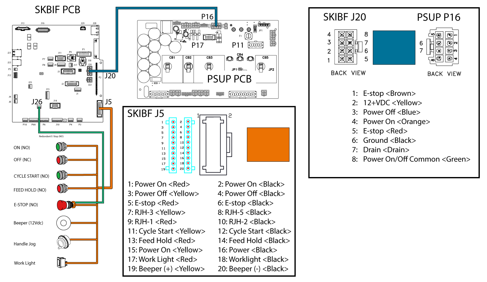
There is problem with the [POWER ON] or [POWER OFF] circuit. Make sure that the wires going to the [POWER ON] [POWER OFF] contactors terminals are secure. Check the cable from SKIBF to PSUP PCB see the above electrical diagrams.
The main circuit breaker is defective.
  1. Turn off the machine's main circuit breaker.
  2. Turn off the electrical service to the machine.
  3. Make sure that there is no voltage to the machine.
  4. Turn the machine's main circuit breaker to the ON position.
  5. Measure continuity between the top and bottom poles. If there is no continuity, replace the circuit breaker.
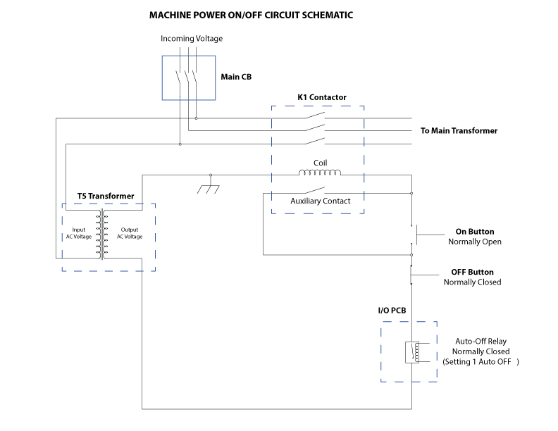
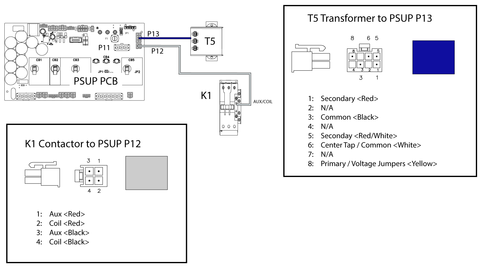
The K1 contactor coil is not receiving power or the wires are not connected on the correct terminals on the coil. Check that the K1 contactor is receiving approximately 24 VAC from the T5 transformer. See above diagrams.
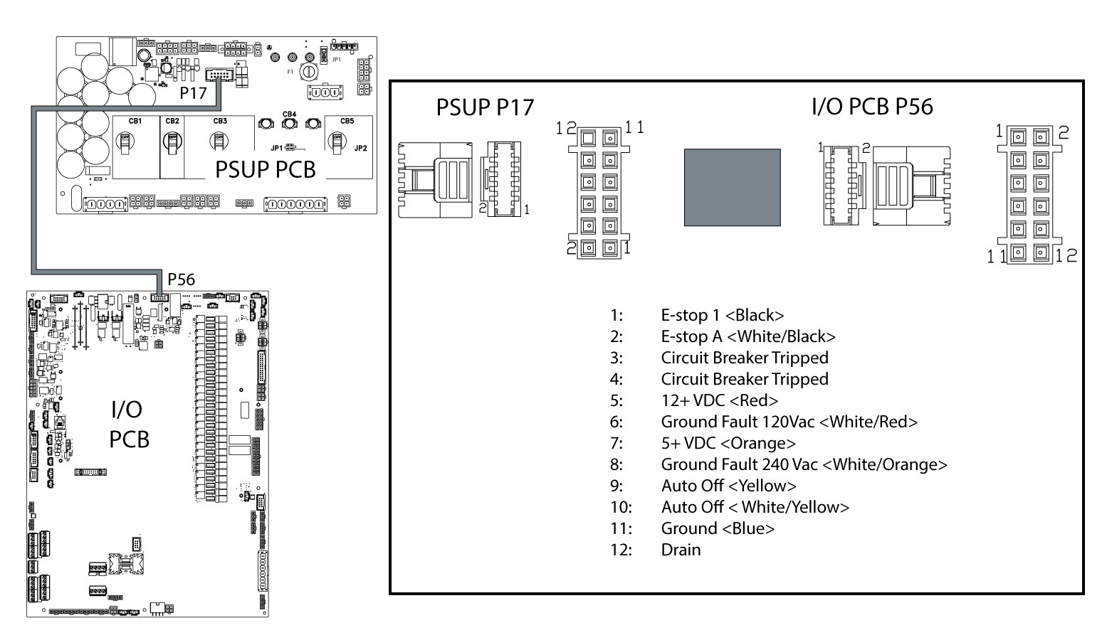
The auto off circuit is open. Check the cable connection from the PSUP (P17) to I/O PCB (P56).
Machine equipped with CABCOOL shuts off intermittently. The main transformer is not tapped in the correct range. Measure the incoming voltage and check that the main transformer taps are placed on the correct range.  Note:  The main transformer generates a 240V/120V .  The cabcool runs off the 120V, if the 120V is not at nominal, then when the Cabcool turns on, the voltage can sag and cause the machine to turn off.  
The CABCOOL thermal switch outlet (32-0376A) wiring is on the same phase that PSUP monitors for low voltage condition. Refer to the CABCOOL - Troubleshooting Guide.
The main transformer installed on the machine is not compatible with the CABCOOL option.  Note:  This probable cause does not apply to machines with the 480V option. Refer to the CABCOOL Installation procedure for correct power requirements.  
The machine will not turn on. The F1 fuse is blown on the PSUP.

Check F1 fuse on PSUP and replace if necessary.

Check the JP1 jumper to be installed on PSUP if the machine has a High Voltage service input (380-480 VAC).

Note: If the machine has a 60 hp vector drive, make sure a 2A CERAMIC FUSE is installed at F1.

T5 Transformer Troubleshooting

The T5 transformer is a step down transformer that steps down the incoming voltage to approximately 24VAC. When the [POWER ON]  button is pressed this voltage is applied to the coil on the K1 contactor, then the machine will turn on.

Transformer Primary Check:

  1. Make sure the jumper is in the correct position for the input voltage.
  2. Disconnect the T5 transformer from the PSUP PCB.
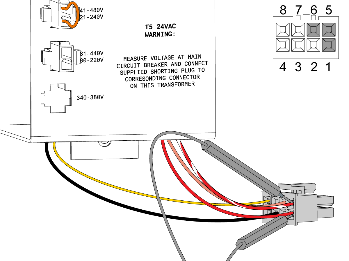
  3. Find the cable for the T5 transformer. Measure the resistance between pins 3 (black) and 8 (yellow) on the cable. Use a multimeter set to ohms.
  4. When the T5 transformer operates correctly, you have one of these conditions:

Low Voltage T5 Transformer (32-1964)

  • Jumper at (221-240V) position the multimeter measures between 54 - 66 ohms.
  • Jumper at (180-220V) position the multimeter measures between 45 - 55 ohms.

High Voltage T5 Transformer (32-1965)

  • Jumper at (441 - 480V) position the multimeter measures between 216 - 264 ohms.
  • Jumper at (381- 440V) position the multimeter measures between 180 - 220 ohms.
  • Jumper at (340- 380V) position the multimeter measures between 153 - 187 ohms.

Voltage Check

  1. Make sure the jumper is in the correct position for the input voltage.
  2. Use a multimeter set to Volts AC measure across pins 1 and 5, 1 and 6, 5 and 6.
  • You should measure 21.6 - 26.4 VAC between pins 1 and 5.
  • You should measure 10.8 - 13.2 VAC between pins 1 and 6.
  • You should measure 10.8 - 13.2 VAC between pins 5 and 6.

Electrical Diagrams

Machine Power On/Off Diagram

PSUP (P16) to SKIBF (J20) / SKIBF (J5) Detail Diagram

PSUP (P17) to I/O PCB (P56) Detail Diagram

T5 to PSUP (P13) / K1 to PSUP (P12) Detail Diagram

17.4 Circuit Breaker - Troubleshooting Guide

Recently Updated

Circuit Breaker - Troubleshooting Guide


TG0051

Circuit Breaker Testing

Symptoms Table

Symptom

Probable Cause

Solution

Alarm 552 TRIPPED CIRCUIT BREAKER There is a short circuit on the Coolant Pump Motor or Cable. Refer to the Standard Coolant - Troubleshooting Guide : Defective Pump section.
The circuit breaker is defective. Test the circuit breaker inrush current and duration time.  Refer to the Coolant Pump Breaker Troubleshooting section below.
The PSUP PCB is defective. If the machine generates alarm 552 and the circuit breaker did not trip, then the PSUP may be at fault.  Refer to the PSUP PCB Troubleshooting Guide: PCB Inspection component section.

Coolant Pump Circuit Breaker

This guide is meant to be used for troubleshooting circuit breakers 61-7361 (10A) and 61-7352 (15A) used for machine coolant applications.
Note: This guide does not apply to the Variable Flow coolant or the Shower coolant option as these use VFDs.  

Required Tools:

  • AC Clamp Meter able to measure Inrush Current

The table below shows the coolant pump and circuit breaker combination used for the various coolant options. 

Coolant Options

Coolant Pump Motor

Circuit Breaker

Motor Rating / Phases

Current Rating

Location

Standard flood coolant

1.00HP / 3PH or 0.25HP / 1PH

10A

PSUP PCB

High pressure flood coolant

 1.50HP / 3PH

10A

PSUP PCB

TSC 300 PSI

1.50HP / 3PH

15A

PSUP PCB or TMD PCB

TSC 1000 PSI

 3.00HP / 3PH

Measure the Inrush Current and Duration Time

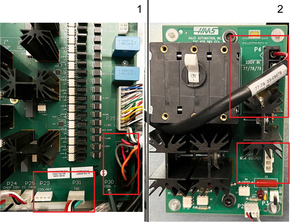
Figure 1: I/O PCB motor power cable connections.  Figure 2: TMD PCB motor power cable connection.

1

Trace back the pump power cable to locate the connection point inside the electrical control.

This will either be on the I/O PCB P29, P31 or the TMD PCB P1 which is mounted on the I/O hinge door depending on the machine.

NOTE FOR TSC

If the strip length on the TSC pump power cable is too tight to fit a current clamp around the individual conductors, the inrush and nominal running current can be measured from cable 33-1980 connected to I/O PCB P30.

If the pump power cable is connected to the I/O PCB. On cable 33-1980 the gray conductor is phase A (77), the orange is phase B (78), and the brown is phase C (79).  

If the TSC pump power cable is connected to the TMD PCB, then the inrush and nominal running current can be measured from cable 33-0987B connected to P4 on the TMD PCB.

On cable 33-0987B the red conductor is phase A (77), white is phase B (78), and black is phase C (79). 

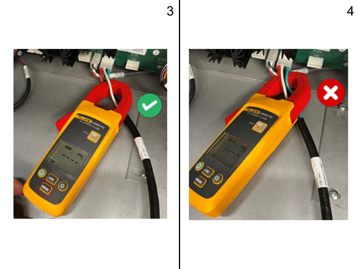
Figure 3: Correct method to measure current.  Figure 4: Incorrect method to measure current.

2

Using a current clamp meter set to measure the Max/Inrush AC current, clamp the meter around a single conductor on the cable.

Turn the pump on and measure the inrush current and its duration time which is the time from the moment the pump is turned on to the time the circuit breaker trips.

Repeat this 2-3 times making sure to record the inrush current and duration time. Repeat this step on all the remaining conductors on the power cable excluding the green ground conductor.

3

Compare the recorded inrush currents and duration times to the NOMINAL COOLANT PUMP INRUSH CURRENT VALUES PER PHASE table on Figure 6.

  • If the breaker did not trip, measure the nominal running current of the pump as described in the section below.

Figure 6: Known nominal inrush values per motor phase for coolant pumps. Values are nominal +/- 20% of the value listed.

NOTE: For TSC and High Pressure Coolant options, do not measure the inrush current with the pump out of the coolant reservoir as these have a pressure switch which will alarm out.

Nominal Coolant Pump Inrush Current Values per Phase

Pump Motor

Red Conductor

White Conductor

Black Conductor

Phase A (77)

Phase B (78)

Phase C (79)

Rating / Phases

Inside Coolant Reservoir

Inside Coolant Reservoir

Inside Coolant Reservoir

0.25HP / 1 PH (SINGLE PHASE MOTOR)

-

5 A

5 A

1.00HP / 3PH

17 A

17 A

17 A

1.50HP / 3PH (TSC)

25 A

25 A

25 A

3.00HP / 3PH (TSC)

32 A

32 A

32 A

Measure the Nominal Running Current

To measure the nominal running current of the pump, the coolant hose at the machine needs to be disconnected to prevent head pressure from skewing the nominal running current measurement.

IMPORTANT:  This does not apply to TSC and the High Pressure Coolant option.

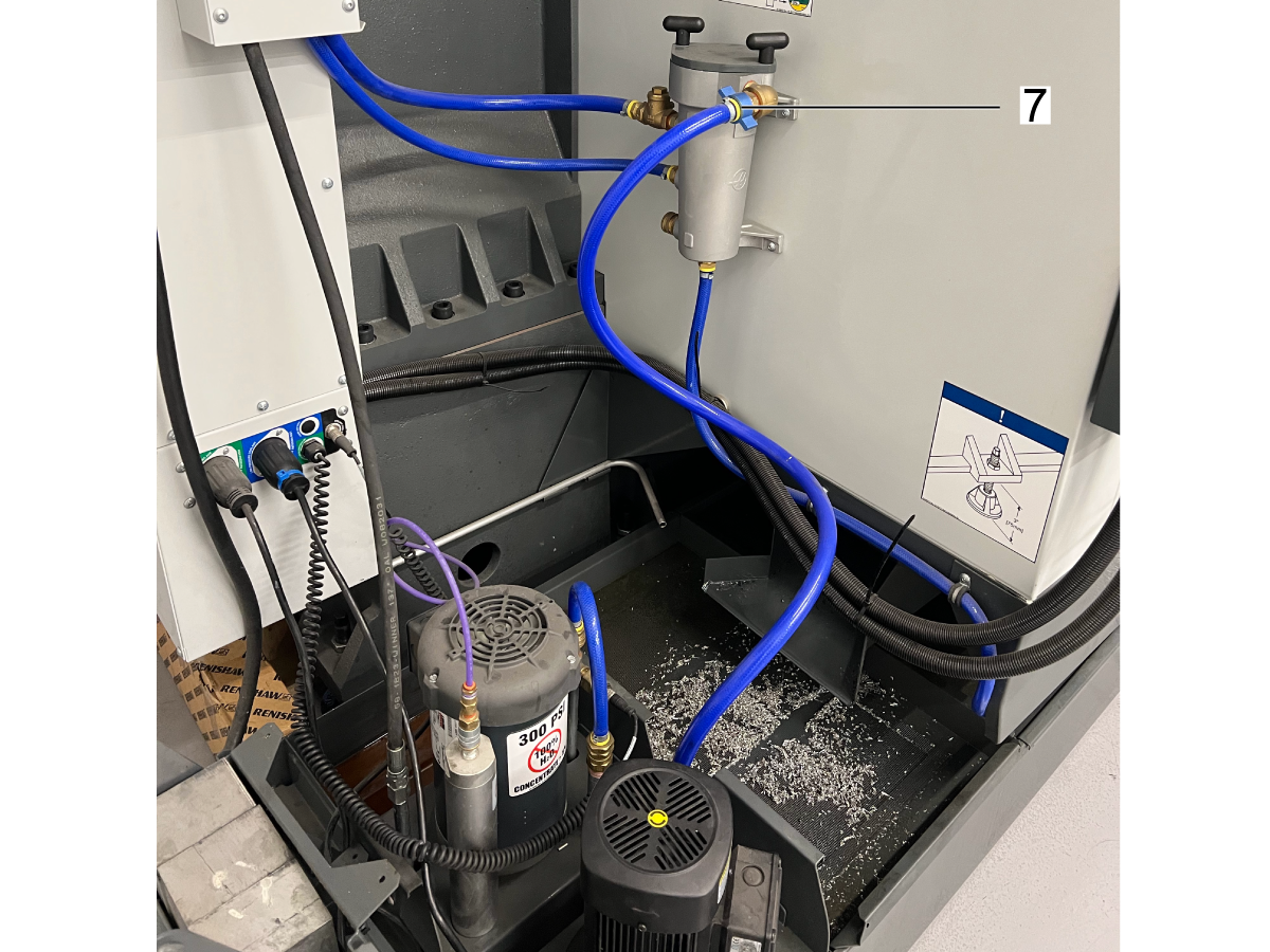
Figure 7: Pump hose for Flood Coolant.

1

Disconnect the coolant hose [7] from the machine and secure the hose tightly to the coolant tank reservoir. This is important as not securing the hose will cause it to spray coolant everywhere. 

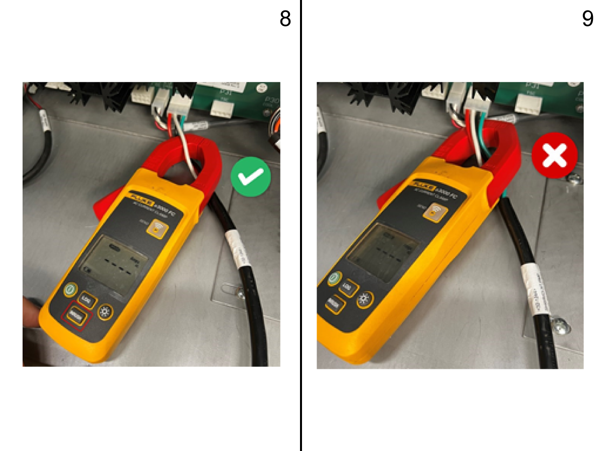
Figure 8: Correct method to measure current.  Figure 9: Incorrect method to measure current.

2

Using a current clamp meter set to measure nominal AC current, clamp the meter around a single conductor on the power cable. After checking the pump hose is secured, turn the pump on and let it run for 5 seconds.

Record the nominal running current from the current clamp and then stop the pump. Repeat this step for all the remaining conductors on the power cable making sure to record the nominal running current for each conductor excluding the green ground conductor. 

3

Remove the pump from the coolant reservoir and repeat step 2 and 3 with the coolant pump outside of the coolant reservoir. 

4

Compare the recorded nominal running current values from step 2 and 3 to the known nominal running current values for the specific pump size as shown below.

  • If the recorded nominal current values are within the known nominal current values +/- 20%, then the pump and circuit breaker are not faulty and the other parts of the coolant system should be inspected.
  • If the recorded nominal current values are higher than the known nominal running current values shown, then the pump needs to be inspected for any faults which could be causing the higher running currents.

Figure 10: Known nominal running current values per motor phase for coolant pumps. Values are nominal +/- 20% of the value listed. For TSC and High Pressure Coolant options, do not measure the nominal running current with the pump out of the coolant reservoir as these have a pressure switch which will alarm out.

Known Nominal Coolant Pump Running Current Values per Phase

Pump Motor

Red Conductor

White Conductor

Black Conductor

Phase A (77)

Phase B (78)

Phase C (79)

Rating / Phases

Inside Coolant Reservoir

Outside  Coolant Reservoir

Inside Coolant Reservoir

Outside  Coolant Reservoir

Inside Coolant Reservoir

Outside  Coolant Reservoir

0.25HP / 1 PH

-

-

1.3 A

0.6 A

1.3 A

0.6 A

1.00HP / 3PH

3 A

1.2 A

3 A

1.2 A

3 A

1.2 A

1.50HP / 3PH (TSC)

3.0 A

Do not measure

3.0 A

Do not measure

3.0 A

Do not measure

3.00HP / 3PH (TSC)

4.5 A

Do not measure

4.5 A

Do not measure

4.5 A

Do not measure

Recently Viewed Items

You Have No Recently Viewed Items Yet

Feedback
Haas Logo

Haas Delivered Price

This price includes shipping cost, export and import duties, insurance, and any other expenses incurred during shipping to a location in France agreed with you as a buyer. No other mandatory costs can be added to the delivery of a Haas CNC Product.

KEEP UP WITH THE LATEST HAAS TIPS AND TECHNOLOGY...

Sign up now!   

HAAS TOOLING ACCEPTS THE FOLLOWING:

  • Service & Support
  • Owners
  • Request Service
  • Operator Manuals
  • Haas Parts
  • Rotary Repair Request
  • Pre-Install Guides
  • Shopping Tools
  • Build & Price a New Haas
  • Available Inventory
  • The Haas Price List
  • CNCA Financing
  • About Haas
  • Accessibility Statement
  • DNSH Statement
  • Export Compliance
  • Careers
  • Certifications & Safety
  • Contact Us
  • History
  • Terms & Conditions
  • Haas Tooling Terms & Conditions
  • Privacy
  • Warranty
  • Haas Community
  • Haas Certification Program
  • Haas Motorsports
  • Gene Haas Foundation
  • Haas Technical Education Community
  • Events
  • Join the Conversation
  • Facebook
  • X
  • Flickr
  • YouTube
  • LinkedIn
  • Instagram
  • TikTok
© 2026 Haas Automation, Inc – CNC Machine Tools
This site is protected by reCAPTCHA and the Google Privacy Policy and Terms of Service apply.

2800 Sturgis Rd., Oxnard, CA 93030
Toll Free: (888) 817-4446 / Fax: 805-278-8554