×

Search Results

Web Pages

Images

    • <
    • 1
    • >
  • machines
    • Haas Vertical Mills
      Vertical Mills
      • Vertical Mills
      • VF Series
      • Universal Machines
      • VR Series
      • Pallet-Changing VMCs
      • Mini Mills
      • Mold Machines
      • Drill/ Tap/ Mill Series
      • Toolroom Mills
      • Compact Mills
      • Gantry Series
      • Vertical Mill/Turn
      • Extra-Large VMC
      • Double-Column Mills
      • Desktop Mill
      • Mill Auto Parts Loader
    • Product Image
      Multi-Axis Solutions
      • Multi-Axis Solutions
      • Y-Axis Lathes
      • 5-Axis Mills
    • Haas Lathes
      Lathes
      • Lathes
      • ST Series
      • Dual-Spindle
      • Toolroom Lathes
      • Chucker Lathe
      • Haas Bar Feeder V2
      • Lathe Auto Parts Loader
    • Haas Horizontal Mills
      Horizontal Mills
      • Horizontal Mills
      • 50-Taper
      • 40-Taper
    • Haas Rotaries & Indexers
      Rotaries & Indexers
      • Rotaries & Indexers
      • Rotary Tables
      • Indexers
      • 5-Axis Rotaries
      • Extra-Large Rotaries
    • Product Image
      Automation Systems
      • Automation Systems
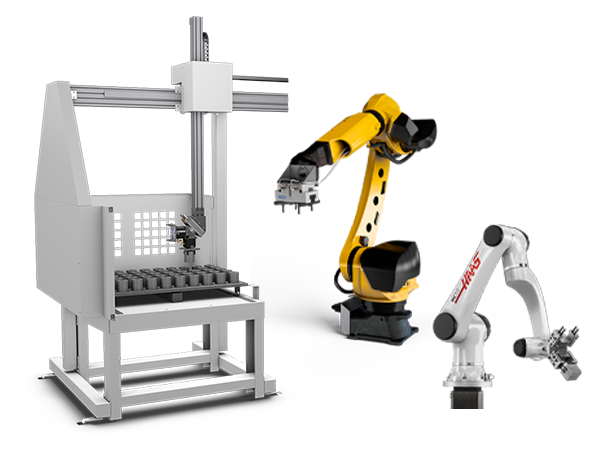
      • Robot Systems
      • Automatic Parts Loaders
      • Pallet-Pool Systems
      • Haas Bar Feeder
      • Models
    • QUICK LINKS Special Series  Special Series 
      HAAS CAREERS HAAS CAREERS BUILD & PRICE BUILD & PRICE PRICE LIST PRICE LIST WHAT’S NEW WHAT’S NEW YOUR FIRST CNC YOUR FIRST CNC HAAS SIX PACK HAAS SIX PACK
      SHOPPING TOOLS
      • Build & Price a Haas
      • Price List
      • Available Inventory
      • CNCA Financing
      WANT TO TALK TO SOMEONE?

      A Haas Factory Outlet (HFO) can answer your questions, and walk you through your best options.

      CONTACT YOUR DISTRIBUTOR >
  • Options
    • Product Image
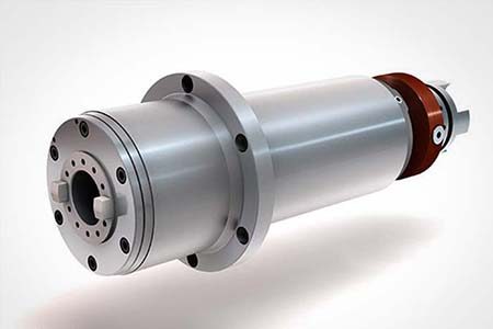
      Spindles
      • Spindles
    • Product Image
      Tool Changers
      • Tool Changers
    • Product Image
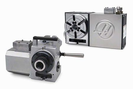
      4th- | 5th-Axis
      • 4th- | 5th-Axis
    • Product Image
      Turrets & Live Tooling
      • Turrets & Live Tooling
    • Product Image
      Probing
      • Probing
    • Haas Chip & Coolant Management
      Chip & Coolant Management
      • Chip & Coolant Management
    • The Haas Control
      The Haas Control
      • The Haas Control
    • Product Image
      Product Options
      • Product Options
    • Product Image
      Tooling & Fixturing
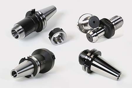
      • Tooling & Fixturing
    • Product Image
      Workholding
      • Workholding
    • Product Image
      5-Axis Solutions
      • 5-Axis Solutions
      • 5 Easy Steps to 5-Axis
    • Product Image
      Automation
      • Automation
    • QUICK LINKS Special Series  Special Series 
      HAAS CAREERS HAAS CAREERS BUILD & PRICE BUILD & PRICE PRICE LIST PRICE LIST WHAT’S NEW WHAT’S NEW YOUR FIRST CNC YOUR FIRST CNC HAAS SIX PACK HAAS SIX PACK
      SHOPPING TOOLS
      • Build & Price a Haas
      • Price List
      • Available Inventory
      • CNCA Financing
      WANT TO TALK TO SOMEONE?

      A Haas Factory Outlet (HFO) can answer your questions, and walk you through your best options.

      CONTACT YOUR DISTRIBUTOR >
  • Why Haas
      Discover the Haas Difference
    • Why Haas
    • MyHaas
    • Education Community
    • Industry 4.0
    • Haas Certification
    • Customer Testimonials
  • Service
      Welcome to Haas Service
      SERVICE HOME Operator’s Manuals How-To Procedures Troubleshooting Guides Preventive Maintenance Haas Parts Haas Tooling Videos
  • Videos
  • Haas Tooling
      Mill Toolholding Mill Workholding Milling Lathe Tooling Lathe Toolholding Lathe Workholding ER Collets & Chucks Holemaking Threading Tool Management Tooling Accessories Package Kits Apparel & Accessories Storage & Handling Measuring & Inspection
    • Haas Tooling
    • Mill Toolholding Shop All
      • End Mill Holders
      • Shell Mill Holders
      • Shrink Fit Holders
      • ER Collet Chucks
      • Milling Chucks & Collets
      • Drill Chucks
      • Pull Studs
      • Mill Toolholding Kits
    • Mill Workholding Shop All
      • Vises
      • Mill Vise Jaws
      • Workholding Accessories
      • Vise Kits
    • Milling Shop All
      • Shell Mill Bodies
      • Milling Inserts
      • End Mills
      • Chamfer Mills & Inserts
      • Indexable End Mill Bodies
      • Ball End Mills
      • Chamfer End Mills
      • Roughing End Mills
      • Indexable Ball End Mills & Inserts
      • Indexable Milling Kits
      • Chamfer Mill Kits
      • Complete Indexable End Mill Kits
      • Dovetail Cutters
      • Indexable Dovetail Cutters
      • Engraving End Mills
      • Burrs
    • Lathe Tooling Shop All
      • Cut-Off Tooling
      • Cut-Off Tooling Kits
      • Turning Inserts
      • Grooving Tools
      • Small ID Grooving & Threading Tools
      • Threading Inserts
      • Threading Toolholders
      • ID Toolholders
      • OD Toolholders
      • Cermet Turning Inserts
      • CBN Turning Inserts
      • Haas Notch Groove and Thread Inserts
      • Haas Notch Groove and Thread Toolholders
      • Broaching Toolholders
      • Broaching Inserts
    • Lathe Toolholding Shop All
      • TL & CL Toolholding
      • BOT Toolholding
      • BMT Toolholding
      • Live Toolholding
      • Reduction Sleeves
      • VDI Toolholding
    • Lathe Workholding Shop All
      • Live Centers
      • Spindle Liners
      • Quick-Change Collets
      • Lathe Collet Chucks
      • 5C Collets
      • 5C Collet Sets
    • ER Collets & Chucks Shop All
      • ER Collets
      • ER Sealed Collets
      • Tap Collets
      • ER Collet Sets & Accessories
      • ER Collet Chucks
      • Straight Shank ER Collet Chucks
      • Straight Shank Keyless Drill Chucks
    • Holemaking Shop All
      • Carbide Drills
      • Indexable Drill Bodies
      • Indexable Drill Inserts
      • Modular Drill Bodies
      • Modular Drill Heads
      • Cobalt Drills & Sets
      • Center Drills
      • Reamers
      • Indexable Drilling Kits
      • Spot Drills
    • Threading Shop All
      • Taps
      • Threading Inserts
      • Threading Toolholders
      • Thread Mills
      • Pipe Taps
      • Drill Tap Kits
    • Tool Management Shop All
      • Tool Presetting Machines
      • Shrink Fit Machines
    • Tooling Accessories Shop All
      • Spindle Taper Cleaner
      • Haas Shop Lift
      • Toolholder Fixtures
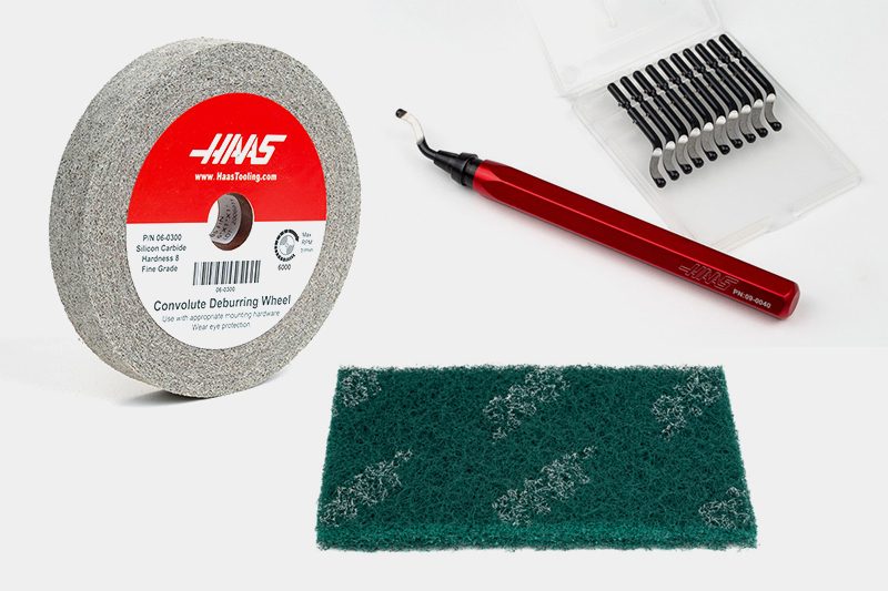
      • Deburr Wheels
      • CNC Clearing Fans
    • Package Kits Shop All
      • Chip Clearing Fan Kits
      • Cutting Tool Kits
      • Complete Indexable End Mill Kits
      • Cut-Off Tooling Kits
      • Drill Tap Kits
      • Indexable Drilling Kits
      • Indexable Milling Kits
      • Chamfer Mill Kits
      • Mill Toolholding Kits
      • Workholding Kits
      • Vise Kits
    • Apparel & Accessories Shop All
      • Accessories
      • Apparel
    • Storage & Handling Shop All
      • Tool Carts
    • Measuring & Inspection Shop All
      • 7-Piece Measuring Kit
      • 3D Sensor Kit, Inch, CT40
      • 3D Sensor Kit, Metric, SK40/DIN
      • 3D Sensor Kit, Metric, BT40
      • 3D Sensor Kit, Inch, HSK63A
      • 3D Sensor Kit, Metric, HSK63A
      • 3D Sensor, Inch
      • 3D Sensor, Metric
      • WIPS Stylus, 3-Pack
      • WIPS Replacement Stylus
      • Spindle Test Bar
      • Coolant Refractometer
      • Clamp Force Gauge
    • HAAS TOOLING QUICK LINKS
      NEW PRODUCTS NEW PRODUCTS
      MOST POPULAR MOST POPULAR
      OPEN TERMS OPEN TERMS
      FINANCING FINANCING
      FAQs FAQs
      KITS CREATED FOR YOU KITS CREATED FOR YOU
  • Haas Service Parts
      Automatic Pallet Changer Lathe Turret Tool Changer Chip Management Coolant Counterbalance Electrical Cabinet Enclosure Hydraulics Lubrication Maintenance Pendant Probing Rotary Spindle Tailstock
    • Haas Service Parts
    • Automatic Pallet Changer Shop All
      • HMC - Automatic Pallet Changer
      • VMC - Automatic Pallet Changer
    • Lathe Turret Shop All
      • Lathe - Turret
      • Live Tooling
    • Tool Changer Shop All
      • Side Mount
      • Umbrella
    • Chip Management Shop All
      • Multi Auger
      • Single Auger
    • Coolant Shop All
      • Auxiliary Filter
      • HPC-300 (Lathe)
      • HPC-1000 (Lathe)
      • Oil Skimmer
      • Standard Coolant
      • TSC-300 (Mill)
      • TSC-1000 (Mill)
      • Coolant Refill
      • Loc-Line
    • Counterbalance Shop All
      • Charge & Discharge Hose
    • Electrical Cabinet Shop All
      • Fans
      • Filters
      • Upgrade Kits
    • Enclosure Shop All
      • Accessories
      • Air Nozzle
      • Decals
      • Door Bumpers
      • Lighting
      • Windows, Gaskets, & Weather Strip
      • Chip & Coolant Management
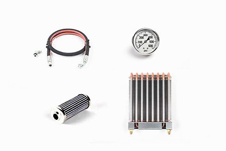
    • Hydraulics Shop All
      • Filters
      • Gauges
      • Heat Exchanger
      • Hoses
    • Lubrication Shop All
      • Bijur Mechanical Lubrication
      • Minimum Lubrication
    • Maintenance Shop All
      • Grease, Oil, & Sealants
    • Pendant Shop All
      • Floppy Disk & USB
      • Keypad
      • Keys
      • Lens
      • Gaskets & Seals
    • Probing Shop All
      • Mill Probing
      • Lathe Tool Presetter
    • Rotary Shop All
      • Rotary Gaskets & Seals
    • Spindles Shop All
      • Couplings
      • Gaskets & Seals
      • Spindle Motor Drive
      • Gearbox Drive
      • Tool Release Piston
    • Tailstock Shop All
      • Handles
  • Contact Us

My Cart
MyHaas Welcome,
!
Haas Tooling Guest Order History MyHaas/HaasConnect Sign In Register Haas Tooling My Account Order History Return History MyHaas/HaasConnect Sign Out Welcome, My Machines Latest Activity My Quotes My Account My Users Sign Out
Find A Dealer
  1. Select Language
    1. English
    2. Deutsch
    3. Español - España
    4. Español - Méjico
    5. Français
    6. Italiano
    7. Português
    8. Český
    9. Dansk
    10. Nederlands
    11. Magyar
    12. Polski
    13. Svenska
    14. Русский
    15. Türkçe
    16. 中文
    17. Suomi
    18. Norsk
    19. الإنجليزية
    20. български
    21. Hrvatski
    22. Ελληνικά
    23. Română
    24. Slovenský
    25. Slovenščina
    26. 한국어
    27. 日本語
Search
×

Search Results

Web Pages

Images

    • <
    • 1
    • >

11 - NGC - 4th and 5th Axis

Next Gen Control Electrical - Service Manual


  • 1 - NGC - Introduction
  • 2 - NGC - Activation
  • 3 - NGC - Software Update
  • 4 - NGC - Firmware Update
  • 5 - NGC - Configuration and Patch Files
  • 6 - NGC - Error Report and Backup
  • 7 - NGC - Main Processor
  • 8 - NGC - I/O and TC PCB
  • 9 - NGC - CAN Systems and Autodoor
  • 10 - NGC - Servo Motors and Axis Cables
  • 11 - NGC - 4th and 5th Axis
  • 12 - NGC - Servo Amplifiers
  • 13 - NGC - Vector Drive
  • 14 - NGC - Regen
  • 15 - NGC - 320V Power Supply
  • 16 - NGC - Wye / Delta
  • 17 - NGC - Circuit Breaker and Transformer
  • 18 - NGC - PSUP PCB
  • 19 - NGC - SKBIF and LCD Monitor
  • 20 - NGC - Remote Jog Handle
  • 21 - NGC - WorkLights and HIL
  • 22 - NGC - CabCool
  • 23 - NGC - MyHaas
  • 24 - NGC - Networking
  • 25 - NGC - 8M PCB
  • 26 - NGC - Robot and Automation
  • 27 - NGC - Machine Data Collection
  • 28 - NGC - Control Icons
  • 29 - NGC - Sensors and Switches
  • 30 - NGC - USB

Go To :

  • 4th and 5th Axis Drive - Installation
  • Rotary - Enable and Disable
  • Reverse Rotary Direction - Setup
Recently Updated

4th and 5th Axis Drive - Installation - NGC


AD0319

Introduction

Refer to the Rotary - Installation procedure to install a TR, TRT, or a T5C rotary unit on a Haas VMC.

Machine Requirements:
  • Mills that have brushless servo amplifiers.
  • Machines with NGC.

Document Applies to these parts:

  • P/N 93-2389 4TH-AXIS DRIVE, NGC
  • P/N 93-1000276 4TH-AXIS DRIVE
  • P/N 93-2544 5TH-AXIS DRIVE, NGC
  • P/N 93-1000275 5TH AXIS DRIVE

Electrical Safety

 Caution: When you do maintenance or repair on CNC machines and their components, you must always follow basic safety precautions. This decreases the risk of injury and mechanical damage.

  • Set the main circuit breaker to the [OFF] position.

 Danger: Before beginning any work inside the control cabinet the High Voltage indicator light on the 320V Power Supply / Vector Drive must have been off for at least 5 minutes.

Some service procedures can be dangerous or life-threatening. DO NOT attempt a procedure that you do not fully understand. If you have any doubts about doing a procedure contact your Haas Factory Outlet (HFO) and schedule a service visit.

Rotary Scale Cable - Installation

Machine Compatibility:  Next Generation Control Machines with a trunnion rotary.

Document Applies to these Parts:

[A] 32-10053 QTY: 1 CABLE, [+12V] ROTARY SCALE FEEDBACK CONTROL END (NGC)

[B] 41-0040 QTY: 4 BOLT, PTHS 4-40X3/8 TRUSS MCMASTER-CARR

1

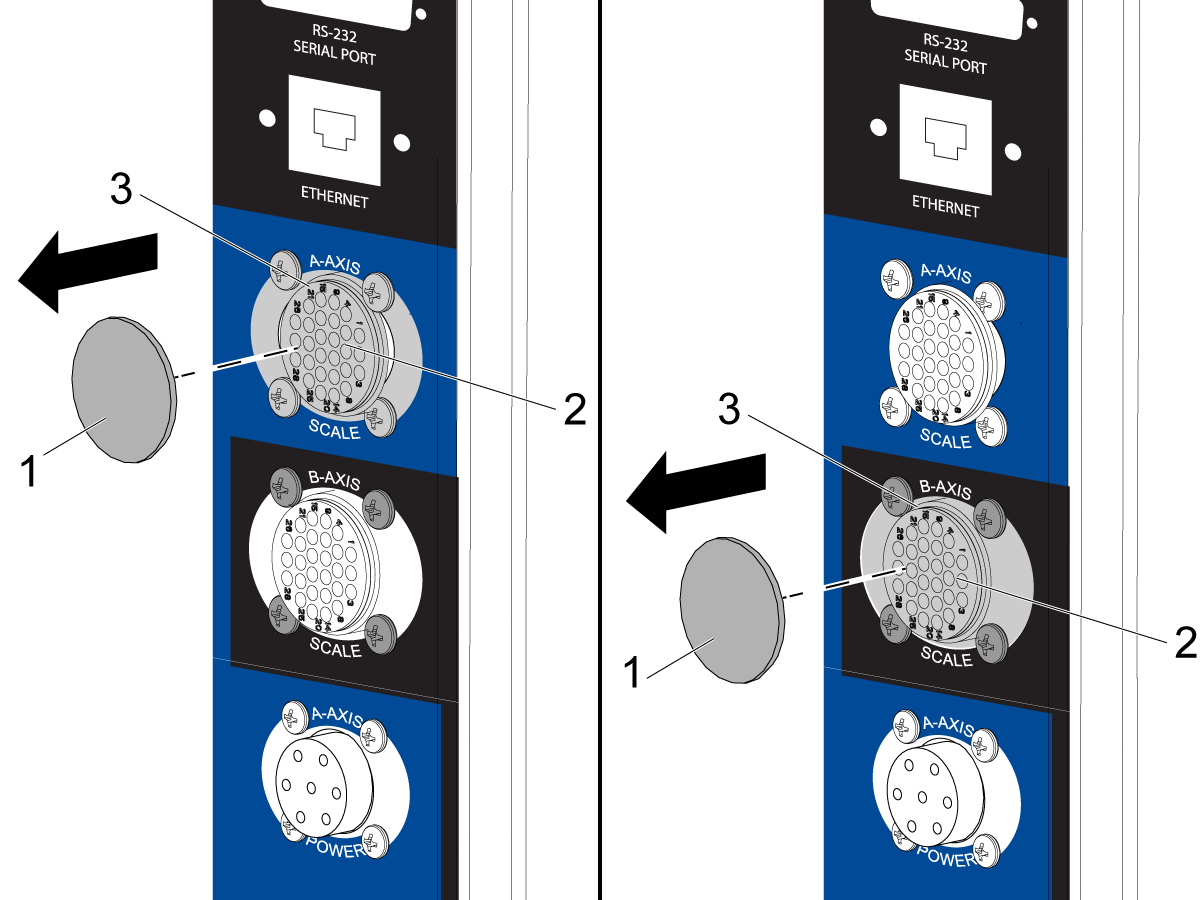
Find the plug [1] for the 4th-AXIS SCALE / A-AXIS SCALE or 5th-AXIS SCALE / B-AXIS SCALE receptacle. The plug is on the side of the control cabinet. Pull the plug out of the hole.

Connect the 28-pin connector [2] from the rotary scale feedback cable to the receptacle. Use the (4) 4-40 screws [3].

2

Remove the center cable track cover and the track cover below the MainCon PCB.

Remove the MainCon PCB cover.

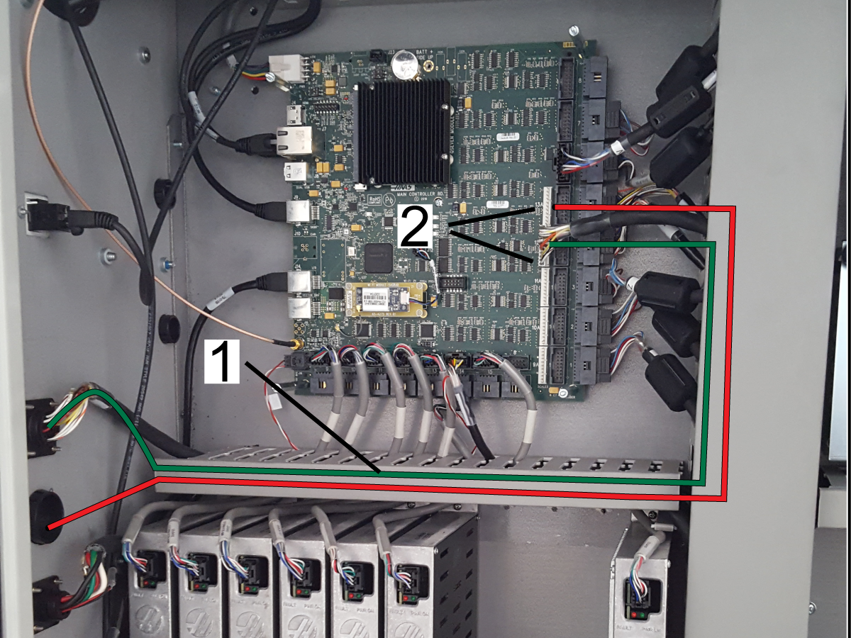
Route the 4th-AXIS SCALE / A-AXIS SCALE or 5th-AXIS SCALE / B-AXIS SCALE cable [1] as shown.

Connect the 11-pin connector of the rotary scale feedback cable to the correct connector on the MainCon PCB:

  • 4th-AXIS SCALE / A-AXIS SCALE Scales Channel 12A (P36)
  • 5th-AXIS SCALE / B-AXIS SCALE Scales Channel 13A (P37)

Install the covers.

4th Drive - Installation - Mill

1

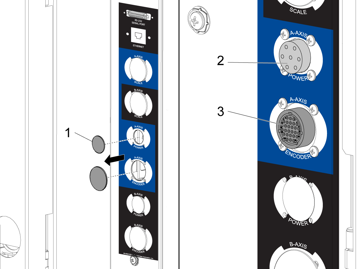
Find the (2) plugs [1] for the 4th-Axis / A-Axis receptacles. The plugs are on the side of the control cabinet. Push the plugs out of the holes.

Install the 7-pin power connector [2] into the receptacle that has the label 4th-AXIS POWER / A-AXIS POWER. Use the (4) screws.

Install the 28-pin encoder connector [3] in the receptacle that has the label 4th-AXIS ENCODER / A-AXIS POWER. Use the (4) screws.

Remove the I/O PCB cover.

Remove the Maincon PCB cover.

2

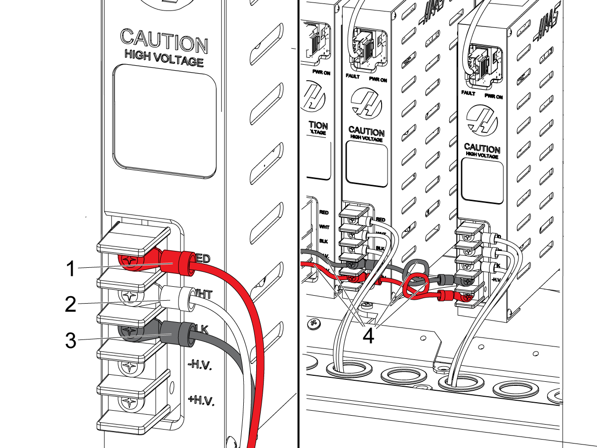
Find the location on the amplifier bank that has the A Axis / 4th Axis label. Install the amplifier for the fourth-axis drive at this location.

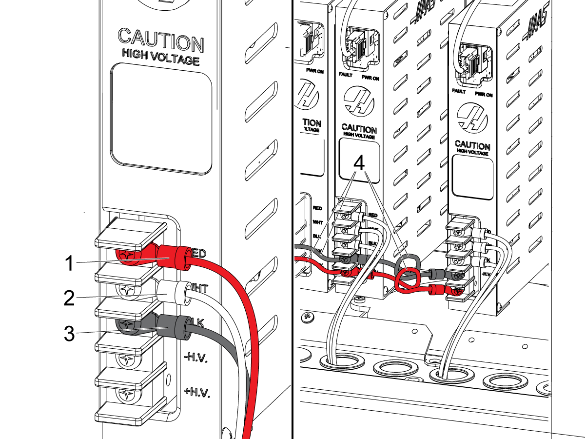
Connect the fourth-axis servo cable wires to the high-voltage terminals on the amplifier:

  • red to RED [1]
  • white to WHT [2]
  • black to BLK [3]

Connect jumpers [4] from the fourth-axis drive to the nearest amplifier on each side:

  • Connect the black wire to -H.V..
  • Connect the red wire to +H.V..

 Caution: On older machines the fourth-axis servo cable may have a shielded wire attached to the black jumper. Connect the shielded wire to -H.V. Do not connect it to the machine ground.

Put the cables in the cable tray.

3

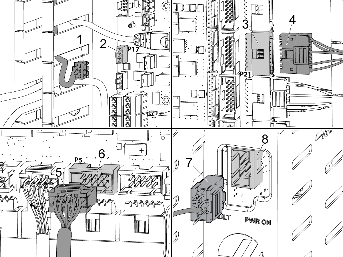
Connect the 3-pin connector [1] on the A-Axis brake cable to P16 [2] on the I/O PCB.

Connect the 16-pin connector [4] on the encoder cable to Encoder Channel 4 (P20) [3] on the Main Control PCB.

Connect the 8-pin connector [5] on the current-command cable to the Amplifier Channel 4 (P4) socket [6] of the Main Control PCB.

Connect the 8-pin connector [7] on the current-command cable to the ampifier [8].

4

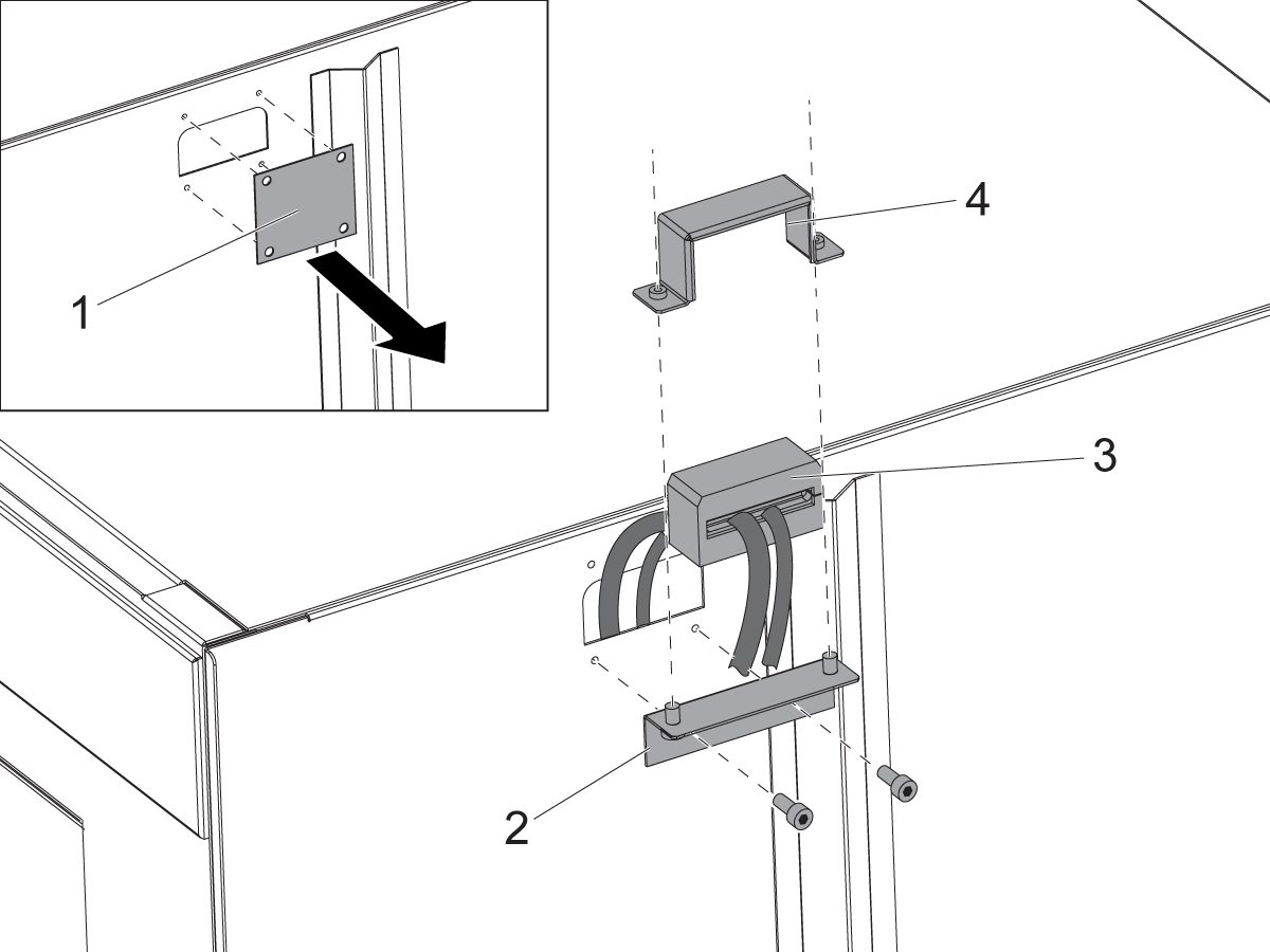
Remove the blanking plate [1].

Install the clamp block mount [2].

Put the rotary cables through the clamp block [3].

Install the clamp block retainer [4].

5

If you are not installing a fifth-axis drive, install the cover plates for the Maincon PCB and I/O PCB.

Set the main circuit breaker to the ON position.

Push [POWER ON].

Refer to: Next Generation Control - Option Activation Code to enable the fourth axis software.

5th Drive - Installation - Mill

1

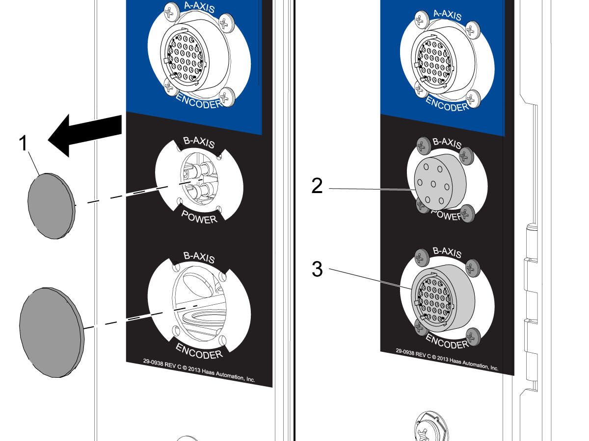
Find the (2) plugs [1] for the 5th-Axis / B-Axis sockets. The plugs are on the side of the control cabinet. Pull the plugs out of the holes.

Install the 7-pin power connector [2] in the location that has the label 5th-AXIS POWER / B‑AXIS POWER. Use the (4) screws.

Install the 28-pin encoder connector [3] in the location that has the label 5th-AXIS ENCODER / B-AXIS ENCODER. Use the (4) screws.

Remove the I/O PCB cover.

Remove the Maincon PCB cover.

2

Find the location on the amplifier bank that has the B Axis label. Install the amplifier for the fifth-axis drive at this location.

Connect the fifth-axis servo cable wires to the high-voltage terminals on the amplifier:

  • red to RED [1]
  • white to WHT [2]
  • black to BLK [3]

Connect jumpers [4] from the fifth-axis drive to the nearest amplifier on each side:

  • Connect the black wire to -H.V..
  • Connect the red wire to +H.V..

 Caution: On older machines the fifth-axis servo cable may have a shielded wire attached to the black jumper. Connect the shielded wire to -H.V. Do not connect it to the machine ground.

Put the cables in the cable tray.

3

Connect the 3-pin connector [1] on the B-Axis brake cable to P17 [2] on the I/O PCB.

Connect the 16-pin connector [3] on the encoder cable to Encoder Channel 5 (P21) [4] on the MainCon PCB.

Connect the 10-pin connector [5] on the current-command cable to the Amplifier Channel 5 (P5) socket [6] of the MainCon PCB.

Connect the 8-pin connector [7] on the current-command cable to the ampifier [8].

4

Remove the blanking plate [1].

Install the clamp block mount [2].

Put the rotary cables through the clamp block [3].

Install the clamp block retainer [4].

5

Install the cover plates for the Maincon PCB and I/O PCB.

Set the main circuit breaker to the ON position.

Push [POWER ON].

Refer to: Next Generation Control - Option Activation Code to enable the fifth axis software.

Recently Updated

Rotary - Enable and Disable - NGC


Introduction

These procedures tell you how to enable, disable, and clear a rotary unit on a machine with the Next Generation Control:

Note: Rotary products equipped with a Sigma-7 motor require software version 100.17.000.2030 or higher for full 4th axis operation.

  • Next Generation Control - Rotary - Enable: Do this procedure after you install a rotary unit. This procedure tells you how to tell the control what rotary unit you installed..
  • Next Generation Control - Rotary - Disable: Do this procedure to temporarily disable the rotary axis while you keep the rotary axis configured.
  • Next Generation Control - Rotary - Clear: Do this procedure when you remove a rotary unit from the machine and you must install a different rotary unit.

Rotary - Enable

Do this procedure after you install a rotary unit. This procedure tells you how to tell the control what rotary unit you installed. Do this procedure on a machine that has the Next Generation Control. This rotary selection tool replaces Setting 30 and 78 used on CHC controls. See enable Rotary axis - CHC for instructions. 

1

Push [POWER ON].

Push [SETTING].

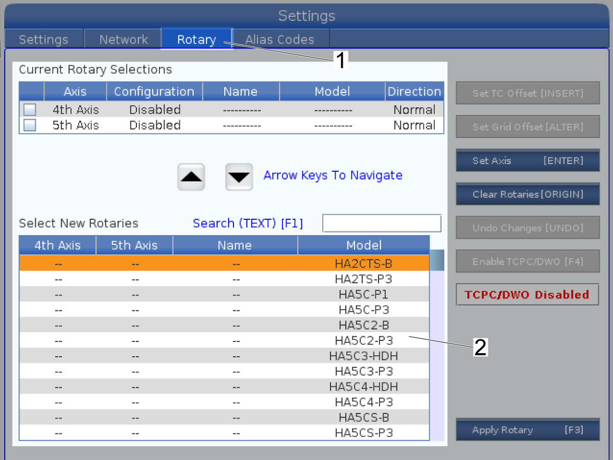
Select the Rotary tab [1].

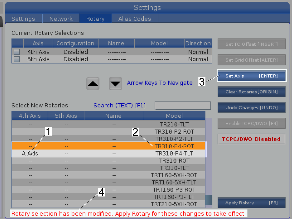
2

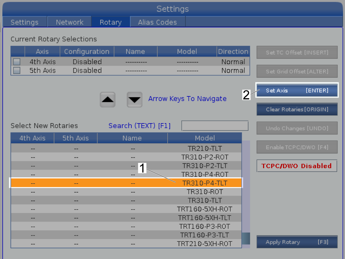
Highlight the 4th Axis rotary unit that is installed [1].

Push [ENTER] to Set Axis [2].

 Note: This screen shows the TR310-P4-TLT rotary.

Note:  If your rotary product does not show up in the list, the control may need to have the rotary configuration updated.  Only Haas techisions can update config files. Contact your HFO to scheadual the update and refer to the Update Rotary Configuration Files procedure.

NOTE: CONFIG FILE NAME INFORMATION

Single axis rotarys require one config file while dual axis require two files. 

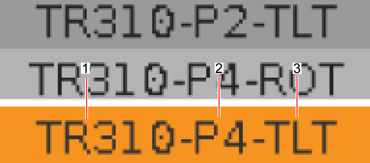
All config file names are broken up into several parts separated by dashes. 

The first part is the model number of the rotary unit [1]. This can be found on the serial plate of the unit. Some Rotary units have a dash in there name, that dash may or may not be in the included in the file name. 

The next part of the file name is the P version number of the unit [2]. This can also be found on the serial plate of the unit.  

The next part of the files only appears on dual axis Rotaries. The next part is either "TLT" or "ROT" [3]. TLT applies to the 4th axis and ROT applies to the 5th axis. Single axis rotaries will not have this part.

The last part of the name is an R at the end. Using this config file would make the Rotary turn in the opiste direction.

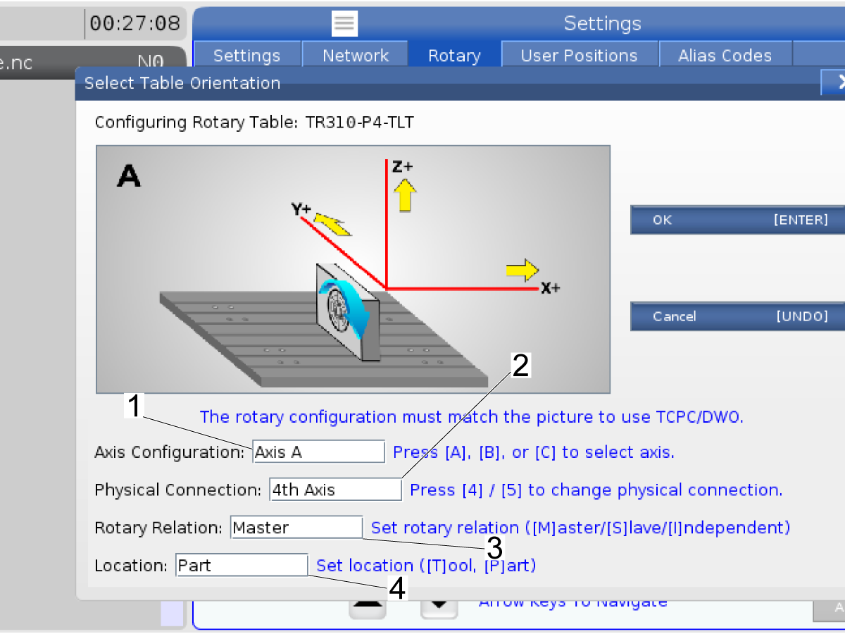
3

The Select Table Orientation [1] screen shows.

Push [A], [B], or [C] to select the Axis Configuration [2]. By defualt the 4th axis is set to A. 

Push [F4] to change the physical connection [3].

For this example the Axis Configuration is Axis A [2] and the Physical Connection is the 4th axis [3].

 Note: To use the Tool Center Point Control (TCPC, G234) or Dynamic Work Offset (DWO, G254), make sure the position of the rotary unit is the same as the illustration on the display.

Push [ENTER] [4].

4

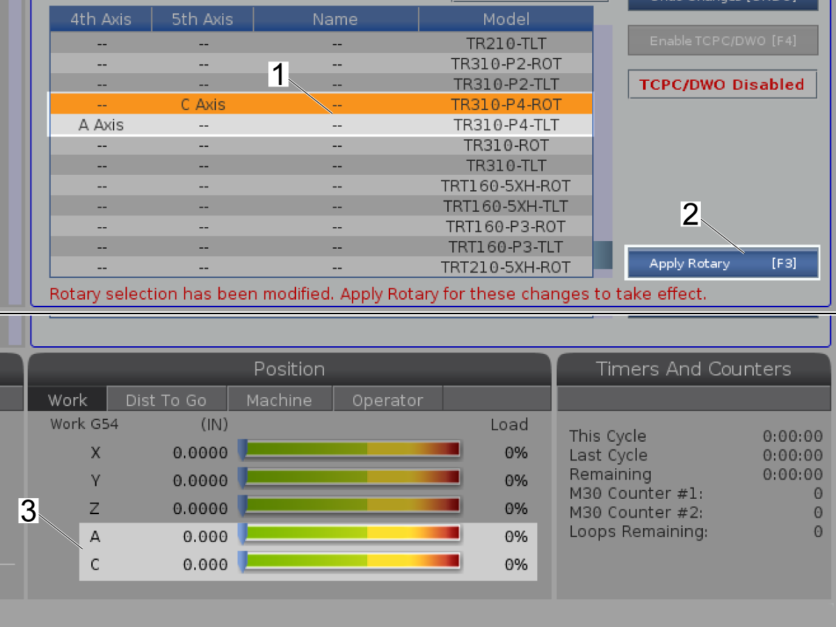
This example sets the TR310-P4-TLT to the A Axis [1].

 Note: The rotary changes do not go into effect until you push [F3] (Apply Rotary) [4]. Go to Step 6 if you are ready to push [F3] (Apply Rotary).

Select the 5th Axis rotary unit that is installed [2].

Push [ENTER] to Set Axis [3].

 Note: This screen shows the TR310-P4-ROT rotary.

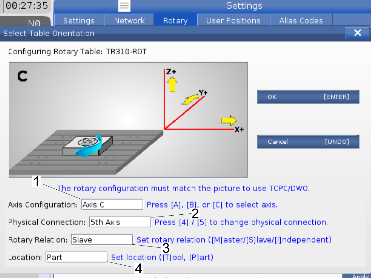
5

The Select Table Orientation [1] screen shows.

Push [A], [B], or [C] to select the Axis Configuration [2]. By defualt the 5th axis is set to C. 

Push [F4] to change the physical connection [3].

For this example the Axis Configuration is Axis C [2] and the Physical Connection is the5th axis [3].

 Note: To use the TCPC or DWO, make sure the position of the rotary unit is the same as the illustration on the display.

Push [ENTER] [4].

6

This example sets the TR310-P4-TLT to the A Axis and sets the TR310-P4-ROT to the C Axis[1].

Push [EMERGENCY STOP].

Push [F3] to Apply Rotary [2].

Go to the next step to use TCPC or DWO. If you do not use TCPC or DWO power cycle the machine.

The A and C Axes show in the display under Position [3].

7

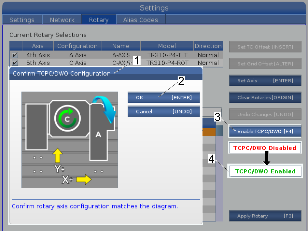
To use TCPC or DWO:

Push [F4] to Enable TCPC/DWO [3].

Confirm TCPC/DWO Configuration [1] shows in the display.

Make sure the position of the rotary unit is the same as the illustration in the display.

Push [ENTER] [2] to confirm.

TCPC/DWO Disabled changes to TCPC/DWO Enabled [4].

Push [F3] to Apply Rotary.

Power cycle the machine.

8

Push [ZERO RETURN]. Start with the X Axis.

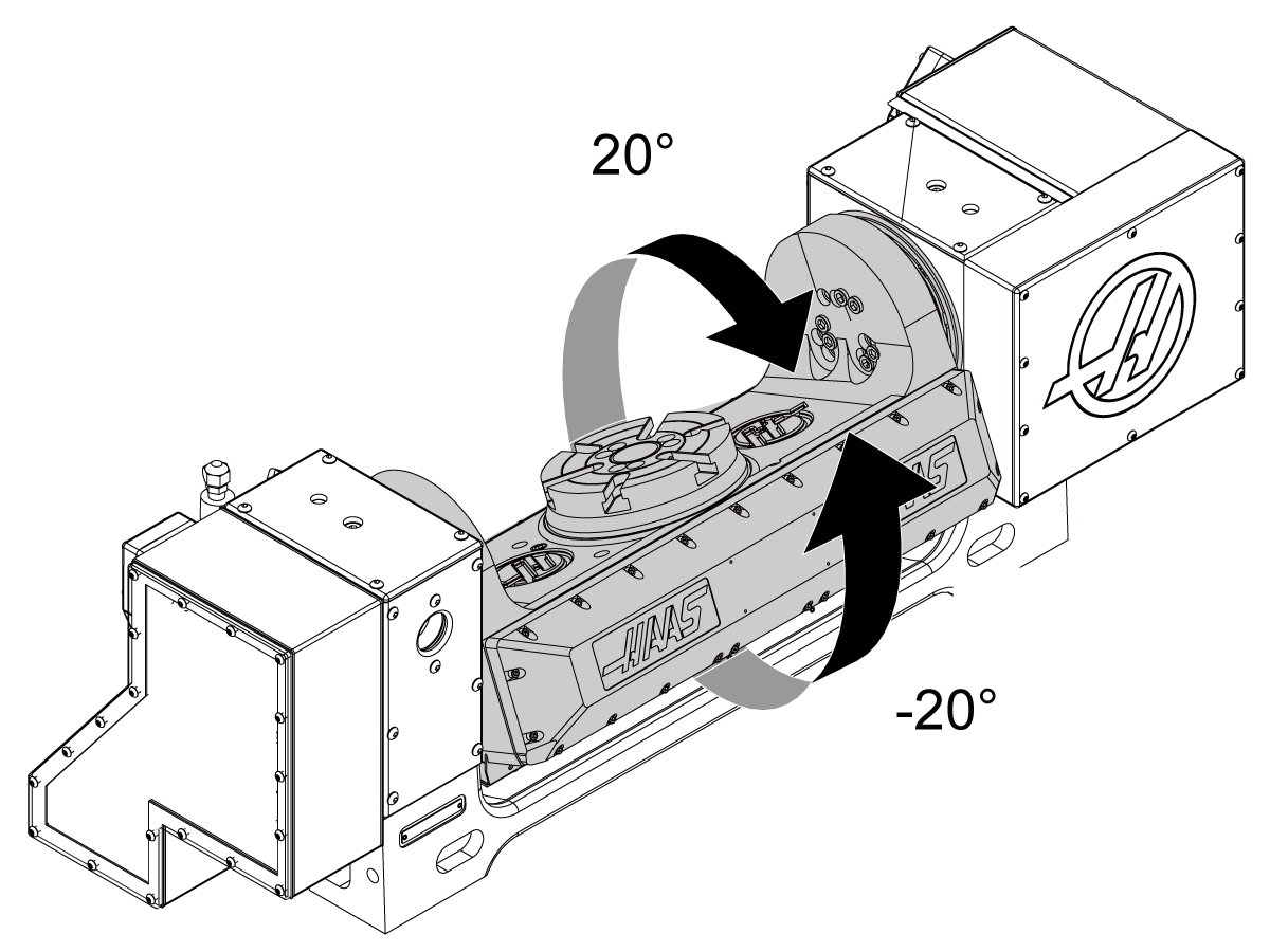
 Caution: If the A axis (tilt) moves more than 20 degrees past the home position,

Push [EMERGENCY STOP] to prevent damage. Make sure that you selected the correct config file for your rotary model, 4TH AXIS ENABLE and, 5TH AXIS ENABLE. If you selected the correct rotary model and axis, speak to your Haas Factory Outlet (HFO).

Jog the machine table to the maximum travel in each axis.

 Caution: Make sure the cables do not get caught on the table or get crushed between the table and the enclosure to prevent damage.

Rotate ("tilt") A axis to get access to the T-Nuts.

Push [EMERGENCY STOP].

Install the remaining studs, washers and nuts.

9

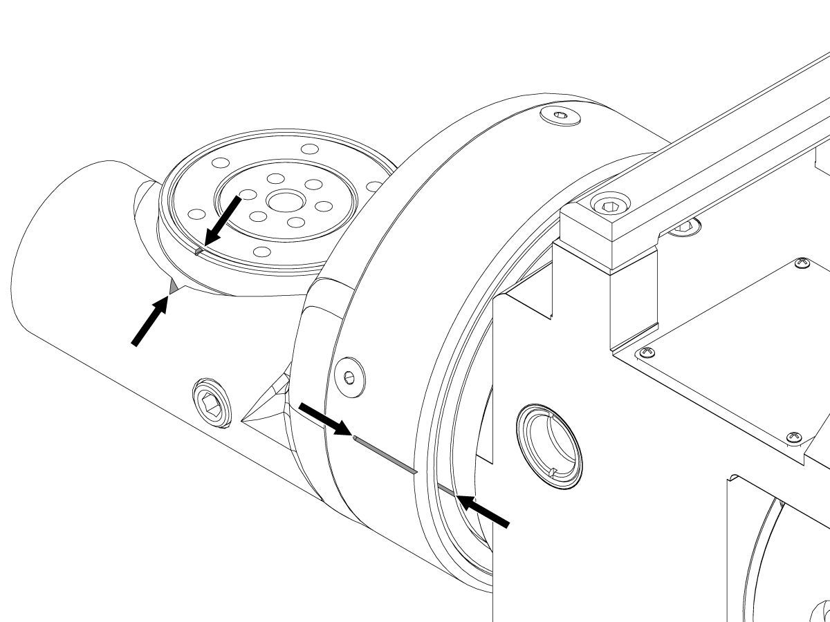
TRT70 Only:

Enable Setting 53 Jog W/O Zero Return.

Jog the A axis (tilt) until the slots are aligned as shown.

Jog the B axis (rotary) until the notches are aligned as shown.

Push [ZERO RETURN], [A].  Wait for the axis to find the home position.

Push [ZERO RETURN], [B].  Wait for the axis to find the home position.

 Caution: Make sure the cables do not get caught on the table or get crushed between the table and the enclosure to prevent damage.

Disable Setting 53 Jog W/O Zero Return.

Rotary - Disable

This procedure tells you how to disable a rotary axis. When you disable a rotary axis, you can prevent it from moving but keep it configured.

1

A rotary axis is enabled when it has a mark [3] to the left of the rotary axis. The rotary axis shows in the Position [4] screen when it is enabled.

Select the rotary axis [1] to disable.

Push [ENTER].

The mark for the rotary axis goes away [5].

The axis goes away from the Position screen [6].

Do this step again for the other rotary axis [2] if necessary.

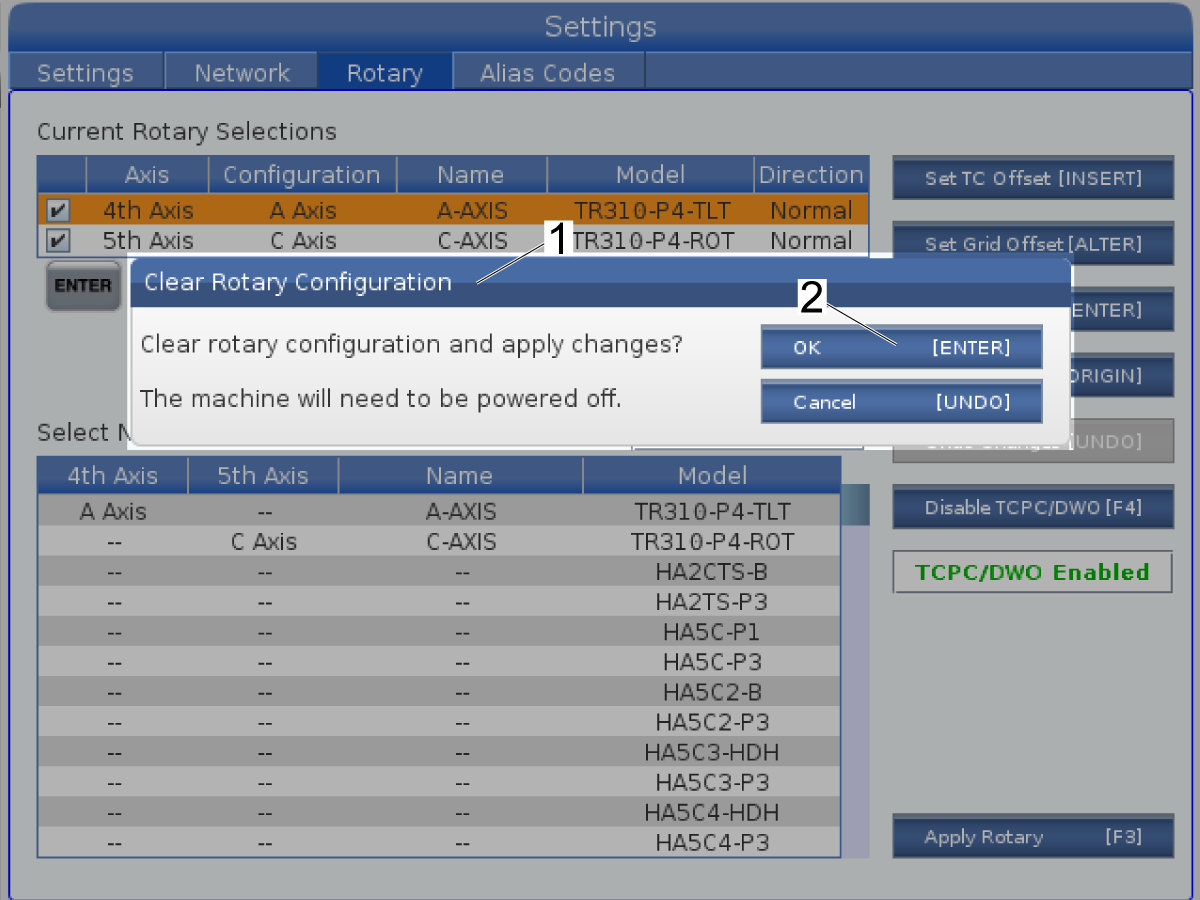
Rotary - Clear

This procedure tells you how to clear a rotary axis configuration from the Current Rotary Selection. Do this procedure when you remove a rotary unit from the machine and you must install a different rotary unit.

1

Push [EMERGENCY STOP].

Push [ORIGIN] to clear the rotaries.

The Clear Rotary Configuration [1] display shows.

Push [ENTER] [2].

Power cycle the machine.

The rotary configurations are cleared from the rotary selection.

Recently Updated

Reverse Rotary Direction Setup - NGC


Introduction

This procedure tells you how to load rotary files to reverse the rotary direction of your Haas rotary configuration. The files supplied only apply to available Haas rotaries.

This procedure is applicable only to Haas rotaries on machines with software version 100.16.000.1030 and higher.

Reverse Rotary Direction Setup - NGC

1

Download and extract the reverse rotary direction files. Log on to the HaasPortal navigate to Service> Documents and Software> Control Software> Next Generation Control Tools> Reverse-Rotary.zip.

Find your rotary model in the extracted folder and copy it to a USB memory device.

Insert the USB memory device with the rotary configuration file into the USB port on the control pendant.

Press [LIST PROGRAM] and navigate to the USB tab [1].

Select your reverse rotary file [2]. Press [ENTER]. The reverse rotary files have an R at the end of the file name.

Press [F2] to copy the reverse rotary file.

Navigate to User Data [3] on the Copy To screen.

2

Press the [RIGHT] CURSOR arrow to enter the User Data directory.

Navigate to the My Rotary directory.

Press the [RIGHT] CURSOR arrow to enter the My Rotary directory [1].

Press [ENTER] [2] to copy the rotary configuration file to this location.

3

Press [SETTING].

Navigate to the Rotary tab [1].

Type the model of your rotary and press [F1] to search. This example uses TR110 [2]. The reverse rotary files have an R at the end of the file name.

Your reverse rotary file [3] is in the Select New Rotaries page.

Press [ENTER] to Set Axis.

4

The Select Table Orientation [1] screen shows.

Press [A], [B], or [C] to select the Axis Configuration [2].

Press [F4] to change the physical connection [3].

For this example the Axis Configuration is Axis A [2] and the Physical Connection is the 4th axis [3].

 Note: The rotary direction must match the rotary direction on the image to use Tool Center Point Control (TCPC, G234) or Dynamic Work Offset (DWO, G254).

Press [ENTER] [4].

Press [F3] to Apply Rotary.

Cycle the power on the machine when you are prompted.

Jog the axis to make sure it operates correctly.

FIND DISTRIBUTOR
Feedback
Haas Logo

美元价格不包括关税、报关费用、保险费、增值税及运费。
USD prices DO NOT include customs duty, customs fees, insurance, VAT, or freight.

人民币价格包含关税、报关费用、货运保险和增值税, 但不包括运费。
CNY prices include customs duty, customs fees, insurance, and VAT. DOES NOT include freight.

Haas Delivered Price

This price includes shipping cost, export and import duties, insurance, and any other expenses incurred during shipping to a location in France agreed with you as a buyer. No other mandatory costs can be added to the delivery of a Haas CNC Product.

KEEP UP WITH THE LATEST HAAS TIPS AND TECHNOLOGY...

Sign up now!   

HAAS TOOLING ACCEPTS THE FOLLOWING:

  • Service & Support
  • Owners
  • Request Service
  • Operator Manuals
  • Haas Parts
  • Rotary Repair Request
  • Pre-Install Guides
  • Shopping Tools
  • Build & Price a New Haas
  • Available Inventory
  • The Haas Price List
  • CNCA Financing
  • About Haas
  • Careers
  • Certifications & Safety
  • Contact Us
  • History
  • Terms & Conditions
  • Haas Tooling Terms & Conditions
  • Privacy
  • Warranty
  • Haas Community
  • Haas Certification Program
  • Haas Motorsports
  • Gene Haas Foundation
  • Haas Technical Education Community
  • Events
  • Join the Conversation
  • Facebook
  • Twitter
  • Flickr
  • YouTube
  • LinkedIn
  • Instagram
  • TikTok
© 2022 Haas Automation, Inc – CNC Machine Tools

2800 Sturgis Rd., Oxnard, CA 93030 / Toll Free: 800-331-6746
Phone: 805-278-1800 / Fax: 805-278-2255

Cookie Notice

We use cookies to improve your user experience. Our Cookie Notice describes which cookies we use, why we use them, and how you can find more information about them. Please confirm you consent to us using analytics cookies. If you do not consent, you may still use our website with a reduced user experience.

Manage Settings

Cookie Notice

We use cookies to improve your user experience. Our Cookie Notice describes which cookies we use, why we use them, and how you can find more information about them. Please confirm you consent to us using analytics cookies. If you do not consent, you may still use our website with a reduced user experience.

Functional Cookies

Analytics Cookies