MyHaas Welcome,
!
Haas Tooling Guest Order History MyHaas/HaasConnect Sign In Register Haas Tooling My Account Order History Return History MyHaas/HaasConnect Sign Out Welcome, My Machines Latest Activity My Quotes My Account My Users Sign Out
Find Your Distributor
  1. Select Language
    1. English
    2. Deutsch
    3. Español - España
    4. Español - México
    5. Français
    6. Italiano
    7. Português
    8. Český
    9. Dansk
    10. Nederlands
    11. Magyar
    12. Polski
    13. Svenska
    14. Türkçe
    15. 中文
    16. Suomi
    17. Norsk
    18. الإنجليزية
    19. български
    20. Hrvatski
    21. Ελληνικά
    22. Română
    23. Slovenský
    24. Slovenščina
    25. 한국어
    26. 日本語
    27. Українська
  • machines Main Menu
    • Haas Vertical Mills Vertical Mills
      Vertical Mills
      Vertical Mills View All
      • Vertical Mills
      • VF Series
      • Universal Machines
      • VR Series
      • VP-5 Prismatic
      • Pallet-Changing VMCs
      • Mini Mills
      • Mold Machines
      • High-Speed Drill Centers
      • Drill/Tap/ Mill Series
      • Toolroom Mills
      • Compact Mills
      • Gantry Series
      • SR Sheet Routers
      • Extra-Large VMC
      • Double-Column Mills
      • Control Simulator
      • Mill Automatic Parts Loader
      • VMC/UMC Side-Loading Automatic Parts Loader
      • Compact Automatic Parts Loader
    • Product Image Multi-Axis Solutions
      Multi-Axis Solutions
      Multi-Axis Solutions View All
      • Multi-Axis Solutions
      • Y-Axis Lathes
      • 5-Axis Mills
    • Haas Lathes Lathes
      Lathes
      Lathes View All
      • Lathes
      • ST Series
      • Dual-Spindle
      • Box Way Series
      • Toolroom Lathes
      • Chucker Lathe
      • Haas Bar Feeder V2
      • Lathe Automatic Parts Loader
    • Haas Horizontal Mills Horizontal Mills
      Horizontal Mills
      Horizontal Mills View All
      • Horizontal Mills
      • 50-Taper
      • 40-Taper
    • Haas Rotaries & Indexers Rotaries & Indexers
      Rotaries & Indexers
      Rotaries & Indexers View All
      • Rotaries & Indexers
      • Rotary Tables
      • Indexers
      • 5-Axis Rotaries
      • Extra-Large Rotaries
    • Special Series
      Special Series
      Special Series View All
      • Special Series
      • EU_Series_Redirect
    • Product Image Automation Systems
      Automation Systems
      Automation Systems View All
      • Automation Systems
      • Mill Automation
      • Lathe Automation
      • Automation Models
    • Haas Drill Centers Desktop Machines
      Desktop Machines
      Desktop Machines View All
      • Desktop Machines
      • Desktop Mill
      • Desktop Lathe
    • Haas Shop Equipment Shop Equipment
      Shop Equipment
      Shop Equipment View All
      • Shop Equipment
      • Bandsaw
      • Knee Mill
      • Surface Grinder, 2550
      • Surface Grinder, 3063
      • Laser Cutting Machine
    • QUICK LINKS Special Series  Special Series 
      EU SERIES EU SERIES BUILD & PRICE | PRICE LIST BUILD & PRICE | PRICE LIST In-Stock Machines In-Stock Machines WHAT’S NEW WHAT’S NEW YOUR FIRST CNC YOUR FIRST CNC
      SHOPPING TOOLS
      • Build & Price a Haas
      • Price List
      • Available Inventory
      • CNCA Financing
      WANT TO TALK TO SOMEONE?

      A Haas Factory Outlet (HFO) can answer your questions, and walk you through your best options.

      CONTACT YOUR DISTRIBUTOR >
  • Options Main Menu
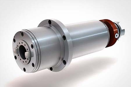
    • Product Image Spindles
      Spindles
      Spindles View All
      • Spindles
    • Product Image Tool Changers
      Tool Changers
      Tool Changers View All
      • Tool Changers
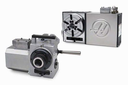
    • Product Image 4th- | 5th-Axis
      4th- | 5th-Axis
      4th- | 5th-Axis View All
      • 4th- | 5th-Axis
    • Product Image Turrets & Live Tooling
      Turrets & Live Tooling
      Turrets & Live Tooling View All
      • Turrets & Live Tooling
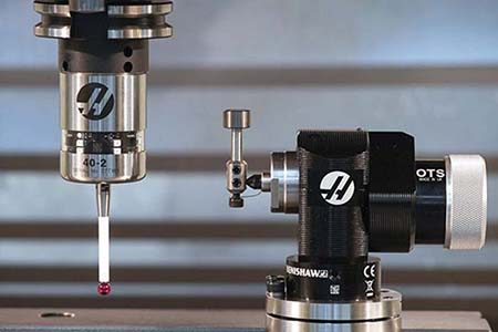
    • Product Image Probing
      Probing
      Probing View All
      • Probing
    • Haas Chip & Coolant Management Chip & Coolant Management
      Chip & Coolant Management
      Chip & Coolant Management View All
      • Chip & Coolant Management
    • The Haas Control The Haas Control
      The Haas Control
      The Haas Control View All
      • The Haas Control
    • Product Image Product Options
      Product Options
      Product Options View All
      • Product Options
    • Product Image Tooling & Fixturing
      Tooling & Fixturing
      Tooling & Fixturing View All
      • Tooling & Fixturing
    • Product Image Workholding
      Workholding
      Workholding View All
      • Workholding
    • Product Image 5-Axis Solutions
      5-Axis Solutions
      5-Axis Solutions View All
      • 5-Axis Solutions
      • 5 Easy Steps to 5-Axis
    • QUICK LINKS Special Series  Special Series 
      EU SERIES EU SERIES BUILD & PRICE | PRICE LIST BUILD & PRICE | PRICE LIST In-Stock Machines In-Stock Machines WHAT’S NEW WHAT’S NEW YOUR FIRST CNC YOUR FIRST CNC
      SHOPPING TOOLS
      • Build & Price a Haas
      • Price List
      • Available Inventory
      • CNCA Financing
      WANT TO TALK TO SOMEONE?

      A Haas Factory Outlet (HFO) can answer your questions, and walk you through your best options.

      CONTACT YOUR DISTRIBUTOR >
  • Why Haas Main Menu
      Discover the Haas Difference
    • Why Haas
    • MyHaas
    • Education Community
    • Industry 4.0
    • Haas Certification
    • Customer Testimonials
  • Service Main Menu
      Welcome to Haas Service
      SERVICE HOME Operator’s Manuals How-To Procedures Troubleshooting Guides Preventive Maintenance Haas Parts Haas Tooling Videos
  • Videos Main Menu
  • Main Menu
    • View All
    • View All
      • Fiber Laser
    • View All
    • View All
      • HTEC Curriculum Support
    • View All
      • Haas 10 kg Cobot Package
      • Cobot Kits
    • View All
    • View All
      • 4 - AUTOMATION SYSTEMS
      • Mill Toolholding
      • Carousel-V2
    • View All
    • View All
    • View All
      • VF-4SS
    • View All
    • QUICK LINKS Special Series  Special Series 
      EU SERIES EU SERIES BUILD & PRICE | PRICE LIST BUILD & PRICE | PRICE LIST In-Stock Machines In-Stock Machines WHAT’S NEW WHAT’S NEW YOUR FIRST CNC YOUR FIRST CNC
      SHOPPING TOOLS
      • Build & Price a Haas
      • Price List
      • Available Inventory
      • CNCA Financing
      WANT TO TALK TO SOMEONE?

      A Haas Factory Outlet (HFO) can answer your questions, and walk you through your best options.

      CONTACT YOUR DISTRIBUTOR >
  • Haas Tooling Main Menu
      Automation Accessories Shop Support Mill Toolholding Mill Cutting Tools Boring Systems Mill Workholding Lathe Toolholding Lathe Cutting Tools Lathe Workholding Package Kits ER Collets & Chucks Holemaking Threading Broaching Tombstones & Kits Manual Chucks For Milling Deburring & Abrasives Tool Presetter & Heat Shrinkers Storage & Handling Machine Maintenance Tooling Accessories Apparel & Accessories Measuring & Inspection Winner's Circle Winner's Circle Clearance Today's Hot Deals
    • Haas Tooling
    • Winner's Circle
      Winner's Circle Shop All
      • WINNERS_CIRCLE-1Y
    • Winner's Circle
      Winner's Circle Shop All
      • WC-1Y-EU
    • Today’s Hot Deals
      Today’s Hot Deals Shop All
      • Mill Toolholding
      • Mill Tooling
      • Measuring & Inspection
      • Boring Systems
      • Mill Workholding
      • Shell Mill Kits
      • Lathe Toolholding
      • Lathe Tooling
      • Lathe Workholding
      • ER Collets & Chucks
      • Holemaking
      • Threading
      • Broaching
      • Tool Storage
      • Apparel & Accessories
    • Clearance
      Clearance Shop All
    • Measuring & Inspection
      Measuring & Inspection Shop All
      • Probe Kits & Accessories
      • Edge & Center Finders
      • Comparative Measuring Gauges
      • Height Gauges
      • Calipers
      • Threaded Plug & Ring Gauges
      • Gauge Blocks
      • Pin Gauges
      • Drop Indicators
      • Dial Test Indicators
      • Bore Gauges
      • Indicator Accessories
      • V Blocks
      • Setup Blocks
      • Depth Measuring
      • Micrometers
      • Micrometer Accessories
      • Micrometer Kits
      • Bore Gauge Kits
      • Starter Kits
      • Indicator Kits
      • Caliper Kits
      • Toolholder Check Station
      • Height Setters
      • Coordinate Measuring Machines
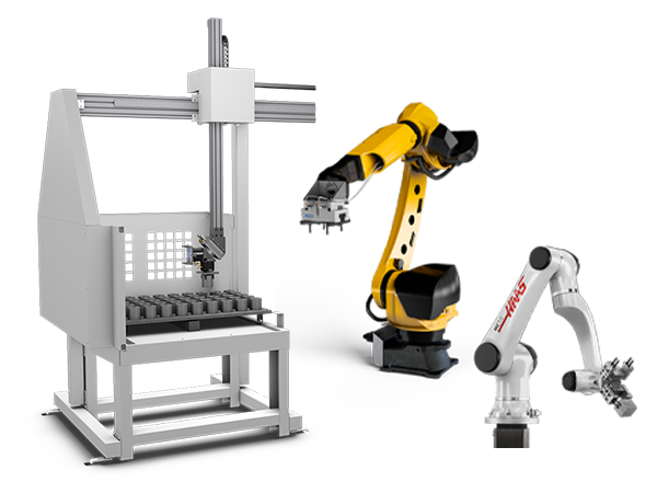
    • Automation Accessories
      Automation Accessories Shop All
      • Cobot Kits
      • Cobot Kits
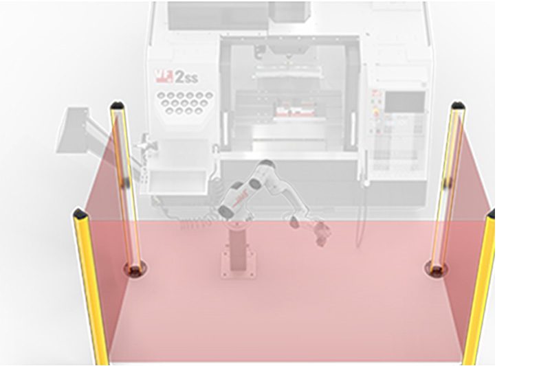
      • Protective Barriers
      • Grippers
      • Robot Cell Accessories
    • Shop Support
      Shop Support Shop All
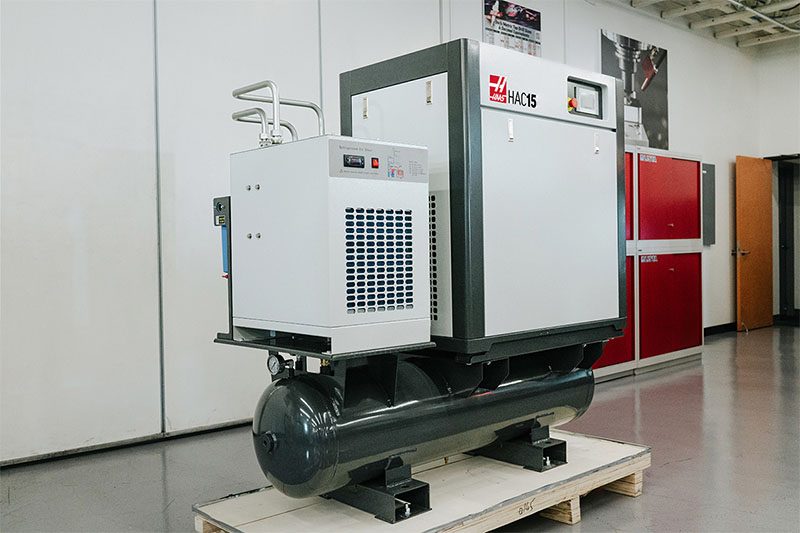
      • Air Compressors
      • Laser Marking Machines
      • Bandsaw Blades
      • Bandsaw Accessories
      • Surface Grinding Wheels
      • Shop Equipment Accessories
    • Mill Toolholding
      Mill Toolholding Shop All
      • End Mill Holders
      • Shell Mill Holders
      • Shrink Fit Holders
      • ER Collet Chucks
      • Milling Chucks & Collets
      • NC Drilling Chucks
      • Pull Studs / Retention Knobs
      • Rotary Tool Holder & Tool Chuck Kits
      • Hydraulic Milling Chucks & Collets
      • Toolholder Attachments & Wrenches
      • Mill Broaching Holders
    • Mill Tooling
      Mill Tooling Shop All
      • Shell Mill Bodies
      • Milling Inserts
      • End Mills
      • Chamfer Mills & Inserts
      • Indexable End Mill Bodies
      • Ball End Mills
      • Chamfer End Mills
      • Roughing End Mills
      • Indexable Ball End Mills & Inserts
      • Shell Mill Kits
      • Chamfer Mill Kits
      • Indexable End Mill Kits
      • Dovetail Cutters
      • Indexable Dovetail Cutters
      • Engraving End Mills
      • Rotary Burrs / Die Grinding Bits
      • Keyseat Cutters
      • Corner Rounding End Mills
      • Slot Mill Bodies
      • CNC Router Bits For Wood
    • Boring Systems
      Boring Systems Shop All
      • Boring Heads & Cartridges
      • Boring Holders & Extensions
    • Mill Workholding
      Mill Workholding Shop All
      • Fixed-Jaw Vises
      • Self-Centering Vises
      • Adapter Plates
      • Vise Jaws
      • Vise Mounts & Fixtures
      • Vise Kits
      • Vise Parallels
      • Rotary Vise Kits
      • Fixture Clamps & Rails
      • Automated Workholding Kits
      • Tooling Fixture Subplates
      • Toolmakers' Vises
      • Clamp Force Gauges
      • Collet Fixtures
      • Angle Plates
    • Lathe Toolholding
      Lathe Toolholding Shop All
      • TL & CL Static Turning Holders
      • BOT Static Turning Holders
      • BMT Static Turning Holders
      • Live / Driven Turning Holders
      • Turning Holder Reduction Sleeves / Bushings
      • VDI Static Turning Holders
      • Turning Holder Accessories
    • Lathe Tooling
      Lathe Tooling Shop All
      • Cut-Off Tool Blocks & Blades
      • Cut-Off Tooling Kits
      • Turning Inserts
      • Grooving & Cut-Off Tools
      • Internal (ID) Grooving & Threading Tools
      • Threading Inserts
      • Threading Tools
      • Boring Bars / Internal (ID) Turning Tools
      • External (OD) Turning Tools
      • Cermet Turning Inserts
      • CBN Turning Inserts
      • Haas Notch Grooving & Threading Inserts
      • Haas Notch Grooving & Threading Tools
      • Micro Turning Tools
      • Desktop Lathe Tools
    • Lathe Workholding
      Lathe Workholding Shop All
      • Live Centers
      • Spindle Reduction Sleeves / Liners
      • Quick-Change Collets
      • Quick-Change Collet Chucks
      • 5C Collets
      • 5C Collet Sets
      • Lathe Jaw Boring Rings
      • Lathe Jaws
      • Bar Pullers
      • Scroll Chucks
      • Guide Pins
      • Collet Accessories
    • Package Kits
      Package Kits Shop All
      • Chip Clearing Fan Kits
      • Cutting Tool Kits
      • Indexable End Mill Kits
      • Cut-Off Tool Block & Blade Kits
      • Drill & Tap Kits
      • Indexable Drilling Kits
      • Shell Mill Kits
      • Chamfer Mill Kits
      • Rotary Tool Holder & Tool Chuck Kits
      • Lathe Starter Kits
      • Workholding Kits
      • Rotary Vise Kits
      • Vise Kits
      • 3-Jaw Chuck Kits for Mills
      • Tombstone Kits
      • Reduction Sleeve Kits
      • Automated Workholding Kits
      • Measuring & Inspection Kits
      • Starter Kits
      • Bore Gauge Kits
      • Caliper Kits
      • Indicator Kits
      • Micrometer Kits
    • ER Collets & Chucks
      ER Collets & Chucks Shop All
      • ER Straight-Bore Collets
      • ER Sealed Collets
      • ER Tap Collets
      • ER Collet Sets & Accessories
      • ER Collet Chucks
      • Straight Shank ER Collet Chucks
      • Straight Shank Keyless NC Drilling Chucks
    • Holemaking
      Holemaking Shop All
      • Carbide Drills
      • Indexable Drill Bodies
      • Indexable Drill Inserts
      • Modular Drill Bodies
      • Modular Drill Heads
      • Cobalt Drills & Sets
      • Center Drills
      • Reamers
      • Indexable Drilling Kits
      • Spot Drills
      • Spade Drill Bodies
      • Spade Drill Inserts
      • Countersinks
    • Threading
      Threading Shop All
      • Taps
      • Threading Inserts
      • Threading Tools
      • Thread Mills
      • Pipe Taps
      • Drill Tap Kits
    • Broaching
      Broaching Shop All
      • Broaching Tools
      • Broaching Inserts
    • Tombstones
      Tombstones Shop All
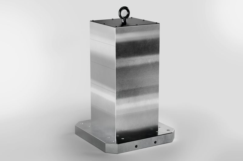
      • Tombstones
      • Tombstone Kits
      • Vise Cluster Towers
    • Manual Chucks For Milling
      Manual Chucks For Milling Shop All
      • 3-Jaw Chucks & Mounts for Mills
    • Deburring & Abrasives
      Deburring & Abrasives Shop All
      • Abrasive Pads
      • Deburr Tools
      • Deburr Wheels
      • Abrasive Sheets & Rolls
      • Sharpening / Lapping Stones
    • Tool Presetter & Heat Shrinkers
      Tool Presetter & Heat Shrinkers Shop All
      • Tool Presetting Machines
      • Shrink Fit Machines
    • Tool Storage
      Tool Storage Shop All
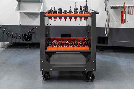
      • Tool Carts
      • Tool Tray
      • Tool Bags
    • Machine Maintenance
      Machine Maintenance Shop All
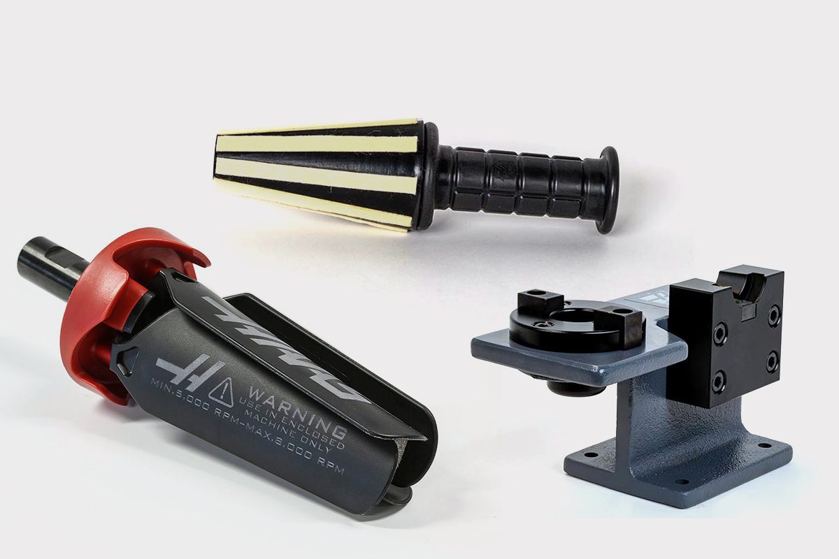
      • Spindle Test Bars
      • Levels
      • Refractometers
      • Machine Additives & Supplies
      • Machine Accessories
      • Machine Maintenance Kits
    • Tooling Accessories
      Tooling Accessories Shop All
      • Spindle & Toolholder Taper Cleaners
      • Haas Shop Lift
      • Toolholder Fixtures
      • CNC Chip Clearing Fans
      • Hammers & Mallets
      • Anti-Fatigue Mats
      • Layout Tools
      • Wrenches
      • Magnetic Tools
      • Torque Screwdrivers
      • Hand Cutting Tools
      • Shop Stools
      • Lifting Magnets
      • Safety Apparel
      • Cutting Tool Sharpeners
    • Apparel & Accessories
      Apparel & Accessories Shop All
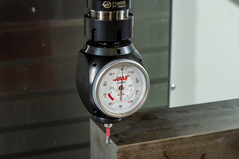
      • Accessories
      • Apparel
    • HAAS TOOLING QUICK LINKS
      NEW PRODUCTS NEW PRODUCTS NEW PRODUCTS NEW PRODUCTS
      MOST POPULAR MOST POPULAR
      TOOLING PROMOS TOOLING PROMOS
      FINANCING & OPEN TERMS FINANCING & OPEN TERMS PAY BY INVOICE PAY BY INVOICE
      FAQs FAQs
      KITS CREATED FOR YOU KITS CREATED FOR YOU
  • Haas Service Parts Main Menu
      Automatic Pallet Changer Lathe Turret Tool Changer Chip Management Coolant Counterbalance Electrical Cabinet Enclosure Hydraulics Lubrication Maintenance Pendant Probing Rotary Spindle Tailstock
    • Haas Service Parts
    • Automatic Pallet Changer
      Automatic Pallet Changer Shop All
      • HMC - Automatic Pallet Changer
      • VMC - Automatic Pallet Changer
    • Lathe Turret
      Lathe Turret Shop All
      • Lathe - Turret
      • Live Tooling
    • Tool Changer
      Tool Changer Shop All
      • Side Mount
      • Umbrella
    • Chip Management
      Chip Management Shop All
      • Multi Auger
      • Single Auger
    • Coolant
      Coolant Shop All
      • Auxiliary Filter
      • HPC-300 (Lathe)
      • HPC-1000 (Lathe)
      • Oil Skimmer
      • Standard Coolant
      • TSC-300 (Mill)
      • TSC-1000 (Mill)
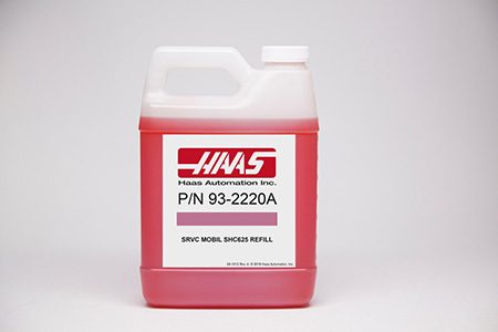
      • Coolant Refill
      • Loc-Line
    • Counterbalance
      Counterbalance Shop All
      • Charge & Discharge Hose
    • Electrical Cabinet
      Electrical Cabinet Shop All
      • Fans
      • Filters
      • Upgrade Kits
    • Enclosure
      Enclosure Shop All
      • Accessories
      • Air Nozzle
      • Decals
      • Door Bumpers
      • Lighting
      • Windows, Gaskets, & Weather Strip
      • Chip & Coolant Management
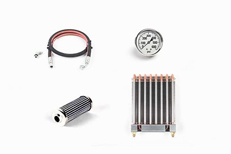
    • Hydraulics
      Hydraulics Shop All
      • Filters
      • Gauges
      • Heat Exchanger
      • Hoses
    • Lubrication
      Lubrication Shop All
      • Bijur Mechanical Lubrication
      • Minimum Lubrication
    • Maintenance
      Maintenance Shop All
      • Grease, Oil, & Sealants
    • Pendant
      Pendant Shop All
      • Floppy Disk & USB
      • Keypad
      • Keys
      • Lens
      • Gaskets & Seals
    • Probing
      Probing Shop All
      • Mill Probing
      • Lathe Tool Presetter
    • Rotary
      Rotary Shop All
      • Rotary Gaskets & Seals
    • Spindles
      Spindles Shop All
      • Couplings
      • Gaskets & Seals
      • Spindle Motor Drive
      • Gearbox Drive
      • Tool Release Piston
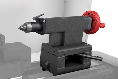
    • Tailstock
      Tailstock Shop All
      • Handles
×

Search Results

Web Pages

Images

    • <
    • 1
    • >
MyHaas Welcome,
!
Haas Tooling Guest Order History MyHaas/HaasConnect Sign In Register Haas Tooling My Account Order History Return History MyHaas/HaasConnect Sign Out Welcome, My Machines Latest Activity My Quotes My Account My Users Sign Out
Find Your Distributor
  1. Select Language
    1. English
    2. Deutsch
    3. Español - España
    4. Español - México
    5. Français
    6. Italiano
    7. Português
    8. Český
    9. Dansk
    10. Nederlands
    11. Magyar
    12. Polski
    13. Svenska
    14. Türkçe
    15. 中文
    16. Suomi
    17. Norsk
    18. الإنجليزية
    19. български
    20. Hrvatski
    21. Ελληνικά
    22. Română
    23. Slovenský
    24. Slovenščina
    25. 한국어
    26. 日本語
    27. Українська
×

Search Results

Web Pages

Images

    • <
    • 1
    • >

7 - VF/VM - Axis Motion

VF/VM-Series - Service Manual


  • 1 - VF/VM - Introduction
  • 2 - VF/VM - Specifications
  • 3 - VF/VM - Installation
  • 4 - VF/VM - Umbrella Tool Changer
  • 5 - VF/VM - HSK - SMTC
  • 6 - VF/VM - 40T/50T - SMTC
  • 7 - VF/VM - Axis Motion
  • 8 - VF/VM - HSK - Spindle
  • 9 - VF/VM - 40T - Spindle
  • 10 - VF/VM - 40T - Spindle Motor
  • 11 - VF/VM - 40T - Gearbox
  • 12 - VF/VM - 50T - Spindle
  • 13 - VF/VM - 50T - Gearbox
  • 14 - VF/VM - Lubrication Systems
  • 15 - VF/VM - Electrical Control
  • 16 - VF/VM - Chip Removal and Coolant
  • 17 - VF/VM - Workholding
  • 18 - VF/VM - Maintenance
  • 19 - VF/VM - Autodoor
  • 20 - VF/VM - Robot and Automation
  • 21 - VF/VM - Enclosure
  • 22 - VF/VM - CAN Bus Systems

Go To :

  • 7.1 Overview
  • 7.2 Service Replacements
  • 7.3 Alignments and Ball Bar
  • 7.4 Servo Motor Troubleshooting
  • 7.5 Ballscrew Troubleshooting

7.1 Overview

Overview

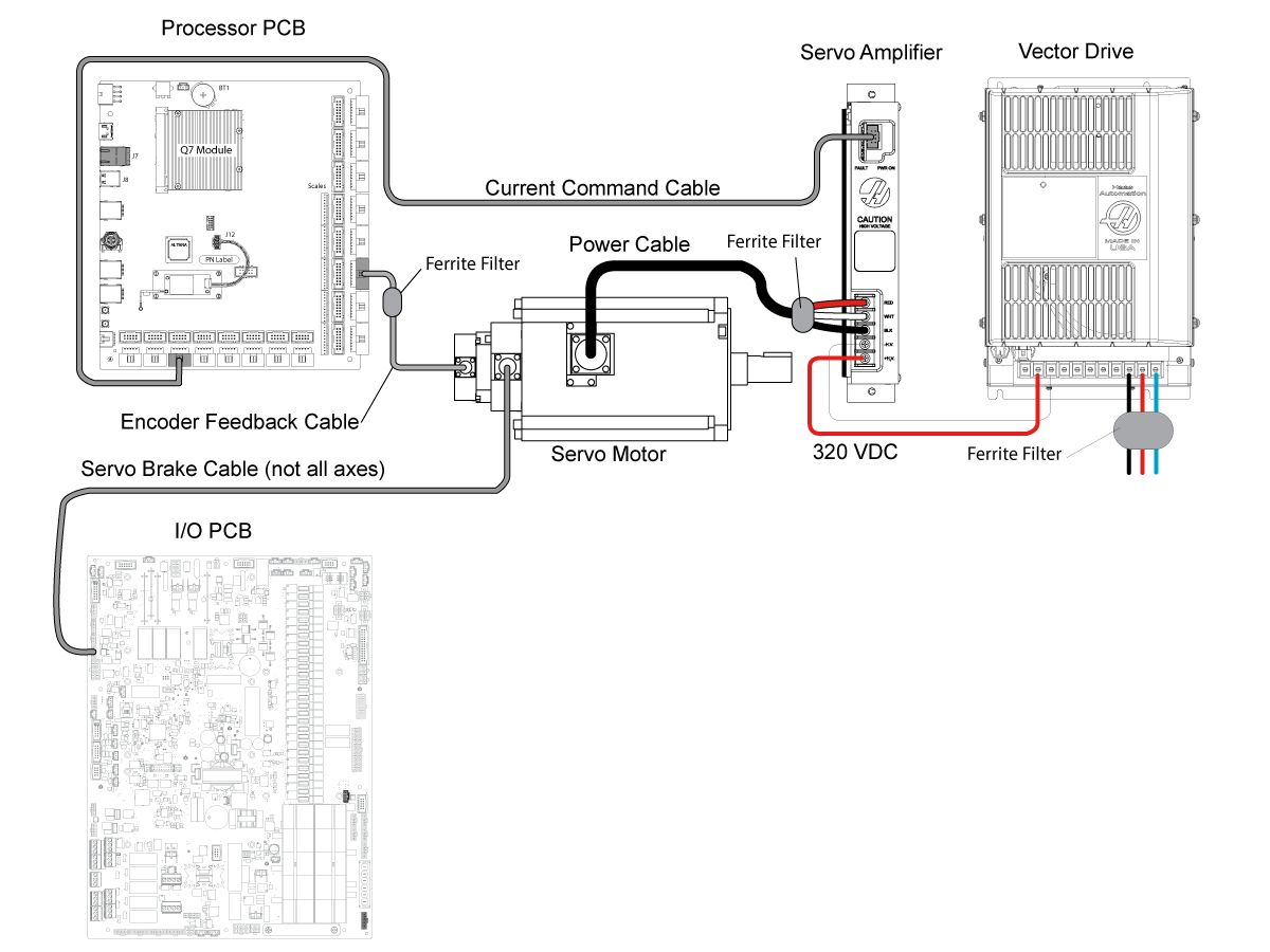
Haas machines are equipped with a close loop system to control axis motion.  Below are the main components:

  • Servo Motor/Encoder
  • Servo Amplifier
  • Vector Drive
  • Processor
  • I/O PCB 

    Note:  For some axis (Z axis in a mill, X axis in a Lathe, Y axis in a Horizontal) motors are equipped with an electromechanical brake, the I/O PCB disengages the brake on those axis when commanded by the processor.

7.2 Service Replacements

Ballscrew Replacement Procedures

Procedure Description
VMC - Ballscrew - 32mm - Horizontal Plane - Replacement This procedure tells you how to replace a X and Y axis ballscrew on the vertical mill.
Ballscrew - Vertical Axis - Replacement This procedure explains how to replace the Z axis ballscrew on the vertical mill.
Ballscrew - Flex Coupling - Replacement This procedure shows you how to replace the flex coupling in a horizontal-plane ballscrew.
32mm Ballscrew Bearing Pack Retrofit Kit - Installation This procedure shows you how to retrofit the 32mm ballscrew bearing pack on a VMC.
40MM - Ballscrew Cartridge Bearing - Upgrade This procedure tells how to upgrade the black oxide bearing to the improved bearing upgrade kit P/N 93-2282.

Servo Motor - Replacement Procedures

Procedure Description
VMC - Z-Axis - Servo Motor - Replacement This procedure tells you how to replace the servo motor on the vertical axis. This procedure applicable for VMC Z axis that is NOT equipped with the counterbalance system and has a solid coupling.

7.3 Alignments and Ball Bar

Ballbar Analysis

Procedure Description
Ballbar Analysis - Quick Check Mode This procedure tells you how to do a ballbar analysis. This procedure uses the Renishaw Ballbar software versions 4 and 5. This procedure uses the Quick Check Mode.
Ballbar - QC20-W - Analysis This procedure tells you how to do a Renishaw QC20-W ballbar analysis. The QC20-W BallBar uses a Bluetooth connection to send the measured data to the computer.
Renishaw Ballbar Test - Plot Interpretation - Mills This document has sample ballbar plots from machines with different geometric, dynamic and test hardware errors.

Ballscrew Backlash Test

Procedure Description
VMC - Ballscrew - Backlash Test - NGC This procedure tells you how to do a test for axis backlash on the X, Y and Z axes of a vertical mill.

Grid Offset Procedure

Procedure Description
Axis Grid Offset Procedure - NGC This procedure will show you how to set the grid offset on a axis servo motor.

7.4 Servo Motor Troubleshooting

Recently Updated

Axis Servo Motor and Cables - Troubleshooting Guide - NGC


Download and fillout the Servo Motor Inspection Report Checklist below before replacing any parts.

Servo Motor Inspection Report Checklist
Related Videos

Electrical Safety

 Caution: When you do maintenance or repair on CNC machines and their components, you must always follow basic safety precautions. This decreases the risk of injury and mechanical damage.

  • Set the main circuit breaker to the [OFF] position.

 Danger: Before beginning any work inside the control cabinet the High Voltage indicator light on the 320V Power Supply / Vector Drive must have been off for at least 5 minutes.

Some service procedures can be dangerous or life-threatening. DO NOT attempt a procedure that you do not fully understand. If you have any doubts about doing a procedure contact your Haas Factory Outlet (HFO) and schedule a service visit.

Symptom Table

Symptom Probable Cause Corrective Action

Alarm 1.9918, 2.9918 or 3.9918 X , Y or Z AXIS SERIAL ENCODER INTERNAL DATA ERROR

Alarm 1.9922, 2.9922 or 3.9922 X, Y or Z AXIS MOTION CHANNEL FAULT DETECTED

Alarm 1.9923, 2.9923 or 3.9923 X, Y or Z AXIS SOFTWARE DETECTED ENCODER FAULT

Alarm 1.9930, 2.9930 or 3.9930 X, Y or Z AXIS SERIAL ENCODER POOR COMMUNICATION

Alarm 1.9959, 2.9959 or 3.9959 X, Y or Z AXIS SERIAL ENCODER DISCONNECT

Alarm 1.9948, 2.9948 or 3.9948  X, Y or Z  AXIS SECONDARY ENCODER SERIAL FAULT

Alarm 1.9949, 2.9949 or 3.9949 X, Y or Z AXIS SOFTWARE DETECTED SECONDARY ENCODER FAULT

Alarm 1.9950, 2.9950 or 3.9950  X, Y or Z AXIS SOFTWARE DETECTED SECONDARY ENCODER FAULT

Alarm 1.9951, 2.9951 or 3.9951  X, Y or Z AXIS SECONDARY ENCODER SERIAL COMMUNICATION FAULT

Alarm 1.9960, 2.9960 or 3.9960  X, Y or Z AXIS SECONDARY SERIAL ENCODER CABLE FAULT

The  machine software is outdated.

Alarm is obsolete 

New alarm for encoder faults updated in software. Update to latest version 100.21.000.1130 or Higher;

Added Alarms 9719 and 9720 for Encoder Fault Detection on Mocon Primary and Secondary Axes.

Alarm 1.9719, 2.9719 or 3.9719 X, Y or Z AXIS PRIMARY ENCODER SERIAL FAULT

Alarm Subcode (0x1) Encoder Data Fault  = (Alarm 9918 SERIAL ENCODER INTERNAL DATA ERROR)

Encoder signals are affected by noise from high power cables.

Faulty servo motor encoder.

Refer to Serial Data Communication Faults / Electrical Noise section below.

Check the servo motor for coolant intrusion. For VMC machines, new servo motor cables can be ordered to mitigate coolant intrusion. See HBC-N 03-13-25.

Alarm 1.9719, 2.9719 or 3.9719 X, Y or Z AXIS PRIMARY ENCODER SERIAL FAULT

Alarm Subcode (0x2) Encoder Internal Axis Fault 1 = (Alarm 9922 MOTION CHANNEL FAULT DETECTED)

(The motion channel has reported an internal fault of a type that is not recognized by the control)

 Cycle power to the machine. If the issue persists, take an error report (Shift F3) and email to Haas Service

Alarm 1.9719, 2.9719 or 3.9719 X, Y or Z AXIS PRIMARY ENCODER SERIAL FAULT

Alarm Subcode (0x3) Encoder Internal Axis Fault 2 =  (Alarm 9923 SOFTWARE DETECTED ENCODER FAULT)

 (Software has reported an internal fault of a type that is not recognized by the control.)

 Cycle power to the machine. If the issue persists, take an error report (Shift F3) and email to Haas Service

Alarm 1.9719, 2.9719 or 3.9719 X, Y or Z AXIS PRIMARY ENCODER SERIAL FAULT

Alarm Subcode (0x4) Encoder CRC Fault =  (Alarm 9930 SERIAL ENCODER POOR COMMUNICATION)

 (Encoder signals are affected by noise from high power cables.)

 (Refer to Serial Data Communication Faults / Electrical Noise section below.)

Alarm 1.9719, 2.9719 or 3.9719 X, Y or Z AXIS PRIMARY ENCODER SERIAL FAULT

Alarm Subcode (0x5) Encoder Cable Fault =  (Alarm 9959 SERIAL ENCODER DISCONNECT)

 (Cables are not connected correctly or encoder is faulty.)  (Inspect the cables and connectors. Refer to the Main Processor/Encoder Cable section below.)

Alarm 1.9720, 2.9720 or 3.9720 X, Y or Z AXIS PRIMARY ENCODER SERIAL FAULT

Alarm Subcode (0x1) Encoder Data Fault  = (Alarm 9948 SECONDARY ENCODER INTERNAL DATA ERROR)

Scale signals are affected by noise from high power cables.

(Faulty Linear Scale, Configuration File issue; incorrect motor type or incorrect Scale type.)

Refer to Serial Data Communication Faults / Electrical Noise section below.

(Check Scale Encoder for coolant contamination.)

Alarm 1.9720, 2.9720 or 3.9720 X, Y or Z AXIS PRIMARY ENCODER SERIAL FAULT

Alarm Subcode (0x2) Encoder Internal Axis Fault 1 = (Alarm 9949 SOFTWARE DETECTED SECONDARY ENCODER FAULT)

(The motion channel has reported an internal fault of a type that is not recognized by the control)  Cycle power to the machine. If the issue persists, take an error report (Shift F3) and email Haas Service

Alarm 1.9720, 2.9720 or 3.9720 X, Y or Z AXIS PRIMARY ENCODER SERIAL FAULT

Alarm Subcode (0x3) Encoder Internal Axis Fault 2 =  (Alarm 9950 SOFTWARE DETECTED SECONDARY ENCODER FAULT)

 (Software has reported an internal fault of a type that is not recognized by the control.)

Cycle power to the machine. If the issue persists, take an error report (Shift F3) and email to Haas Service

Alarm 1.9720, 2.9720 or 3.9720 X, Y or Z AXIS PRIMARY ENCODER SERIAL FAULT

Alarm Subcode (0x4) Encoder CRC Fault =  (Alarm 9951   SECONDARY ENCODER SERIAL COMMUNICATION FAULT )

(Liner Scale signals are affected by noise from high power cables.) (Refer to Serial Data Communication Faults / Electrical Noise section below.)

Alarm 1.9719, 2.9719 or 3.9719 X, Y or Z AXIS PRIMARY ENCODER SERIAL FAULT

Alarm Subcode (0x5) Encoder Cable Fault =  (Alarm 9960 SECONDARY SERIAL ENCODER CABLE FAULT )

(Cables are not connected correctly or Linear scale is faulty.) (Inspect the cables and connectors. Refer to the Main Processor/Encoder Cable section below.)
Alarms 1.161, 2.161, 3.161 X, Y or Z AXIS DRIVE FAULT
Faulty servo amplifier. Check the corresponding amplifier assembly.

Refer to Servo Amplifier - Troubleshooting Guide to troubleshoot the amplifier.

Alarm 1.217, 2.217, 3.217  X, Y or Z AXIS PHASING ERROR Cables are not connected correctly  Inspect the cables and connectors. Refer to the Main Processor/Encoder Cable section below. 
The wrong type of motor has been installed. Check that the correct motor type has been installed.  (Sigma-5 or Sigma-7)
Alarm 1.645, 2.645, 3.645 X, Y or Z AXIS AMPLIFIER GROUND FAULT Faulty power cable. Inspect the cables and connectors. Refer to Power Cable section below.
Faulty servo motor. Check the corresponding servo motor. Refer to Servo Motor section below.
Alarm 1.993, 2.993, 3.993 X, Y or Z AXIS SHORT CIRCUIT Faulty power cable. Inspect the cables and connectors. Refer to Power Cable section below.
Faulty servo motor. Check the corresponding servo motor. Refer to Servo Motor section below.

Alarm 1.103, 2.103, 3.103 X, Y or Z AXIS SERVO ERROR TOO LARGE

Alarm 1.9920, 2.9920, 3.9920 X, Y or Z POSITION ERROR TOO LARGE

Encoder signals are affected by noise from high power cables. Or Faulty encoder. Refer to Serial Data Communication Faults / Electrical Noise section below. Check the encoder steps/revolution versus and ball screw pitch and verify the encoder counts are accurate per each rotation.
The axis motor brake, is not disengaging when servos are enabled. See the Motor Brake section below:
The axis ballscrew is damaged. Check the corresponding axis ballscrew.

Refer to Ballscrew - Troubleshooting Guide to troubleshoot the ballscrew.

Faulty power cable. Inspect the cables and connectors. Refer to Power Cable section below.
Misaligned ballscrew coupling due to a crash

Verify that the ballscrew motor coupling is aligned refer to the Ballscrew - Troubleshooting Guide for further information on how to re-align the coupler

NOTE: Verify that the power cable is not faulty prior to attemping to align the motor coupling. 

Alarm 103 AXIS SERVO ERROR TOO LARGE, during the zero return process. The axis zero returns in the wrong direction. The home sensor is being made during the zero return process causing the axis to zero return in the opposite direction. Check the axis home switch to make sure there are no metal chips on top of the sensor.
Alarm 552 TRIPPED CIRCUIT BREAKER (on UMC-1000) Damaged wire conduit and wires within conduit. Remove back panel. Inspect wire conduit. If damaged, contact Haas Service Department for assistance.
The machine servos make a humming noise while sitting idle, jogging, or on a rapid. The axis grid offset needs to be adjusted. Perform the Axis Grid Offset adjustment procedure.
The ballscrew is not aligned. Verify that the ballscrew does not bind during travel and that it is correctly aligned.
Outdated parameters. Download the latest configuration files. If the axis servo continues to hum, contact your local HFO for more troubleshooting information.
Alarm 9804 240 VAC GROUND FAULT gets generated when I zero return an Axis.
There is a short circuit on the cable or motor. Check for a short circuit on the corresponding servo motor and cable. Watch the Servo Power Cable and Motor Inspection Videos.

Note:  If alarm gets generated on a ST machine when the A-axis is zero returned the LT axis cable and motor must also be check for a short circuit condition.
Alarm 9804 240 VAC GROUND FAULT 
AND/OR
Alarm 993 SHORT CIRCUIT
AND/OR
Alarm 103 AXIS SERVO ERROR TOO LARGE
There may be coolant intrusion on the axis servo motor.

Inspection the motor for coolant intrusion.  For VMC machines, new servo motor cables can be ordered to mitigate coolant intrusion. See HBC-N 03-13-25.

If motor is replaced because of coolant intrusion make sure to order the axis servo motor mount cover for motor mount that have a compatible motor mount cover.

Refer to the VF/VR - X/Y Motor Mount Cover - Reference document to verify motor mounts and their covers. This document wil also have the part numbers for ordering.

Serial Data Communication Faults / Electrical Noise

Sigma-5 servo motors, non-contact encoders output serial data signal to the control. If the serial data signal is missing or becomes unreliable the control will generate a serial data communication error. Electrical noise can cause the serial data signal from the encoder to become unreliable and cause false alarms. Follow the troubleshooting guide below to help eliminate the noise in the system.

  1. Incorrect machine grounding. Make sure the ground wire size is correct. Also the ground wire should run all the way back to the electrical panel.
  2. Noise from other equipment. Make sure the machine does not share it's electrical service with another machine.
  3. Loose encoder data connectors at PCB or at the motor encoder, can cause the serial data to become unreliable. Refer to the Main Processor / Encoder Cable section.
  4. Loose ground or high voltage power connectors will induce noise into the system.
    • electrical cabinet check for loose connection at all the ground and high voltage power terminals (vector drive, wye-delta contactors, transformer..etc).
    • pendant check for loose terminal connectors.
    • spindle head check for loose ground and motor power terminals.
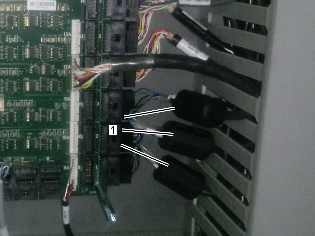
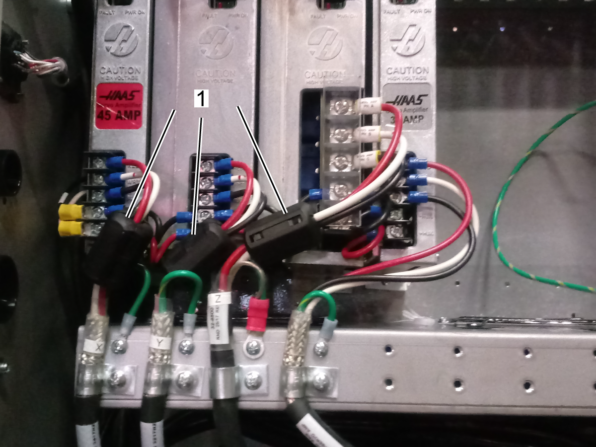
  5. The ferrite filters suppress high frequency noise produced by the amplifiers and vector drive, when servos are on. Make sure they are installed in:
    • Encoder data cables. Make sure there is a ferrite filter P/N 64 1252 installed in all the encoder data cables.
    • Axis motor power cables. Make sure there is a ferrite filter P/N 64-1252 installed in X, Y, Z axis motor power cables [1].
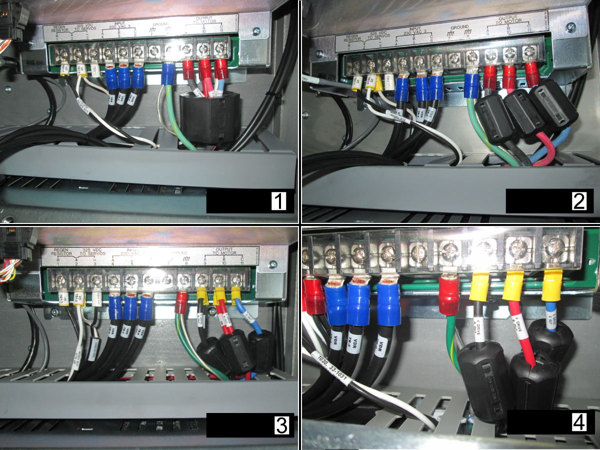
    • Spindle motor cables. Make sure there is a ferrite filter installed in the motor output of the vector drive.

      For a 40HP vector with 6 wire leads [1] use ferrite P/N 64-1254.

      For a 40HP vector with 3 wire leads [2] use ferrite P/N 64-1252.

      For a 20HP vector drive with 6 or 3 wire leads [3, 4] use ferrite P/N 64-1252.

  6. Cable routing. Make sure that the encoder cable is separated from high power spindle/axis/pump cables.

Maincon PCB / Encoder Cable

Corrective Action:

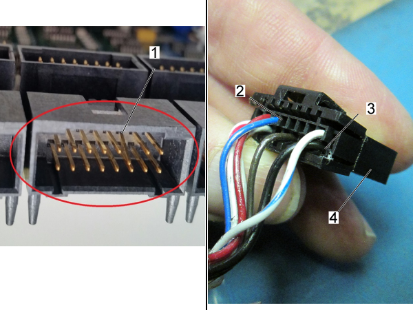
Examine the connector [1] on the Maincon. Make sure it is not damaged.

Examine the cable. Look for signs of damage or stiffness. The connector [4] has two housings [2,3] for the cable pins.

If the pins have been pushed into the motor, you must replace the motor and cable together.

Make sure the cable is firmly connected at both ends. Reseat both connections. Make sure the cable is installed in the correct connector at the Maincon or MOCON PCB.

Power Cable

Inspect the connector at the motor, look for loose connections between motor to cable or between cable spade terminals to amplifier. Check for connector contamination. 

For VMC machines, new servo motor cables can be ordered to mitigate coolant intrusion. See HBC-N 03-13-25.

NOTE: Gently tug on the cables when checking for loose connection on the amplifier side. Pulling on the cables with excessive force can damage them.


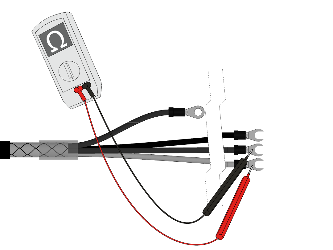
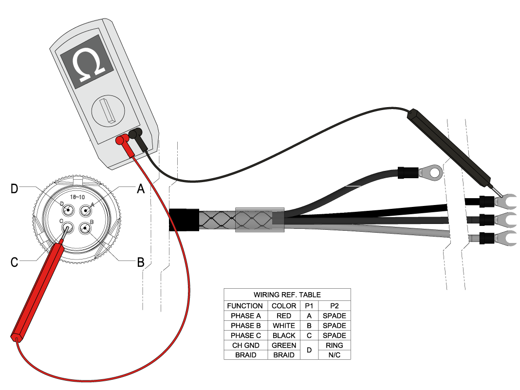
Look for signs of damage and stiffness on the cable and connector. Disconnect the power cable from the amplifier and motor. Measure the resistance from leg to leg (red, white, black wires), and from leg to ground (green/yellow wire). Make sure the measurements result in an open connection. Refer to the table below as a reference. 

NOTE: If the machine is experiencing intermittent short circuit alarms move the axis to the location where the cable would be most bent before performing this test. This may improve the likeliness of finding an intermittent  short.

Servo Power Cable Wiring Reference Table
Function Color  Motor End Amplifiier End
Phase A Red A Spade
Phase B White B Spade
Phase C Black C Spade
Chassis Ground Green/Yellow D Ring
Braid Braid Not Connected

Perform a continuity test between the ground wire and the braided shield. If it fails the continuity test fails the cable shield is compromised. 

NOTE: If the machine is experiencing intermittent short circuit alarms move the axis to the location where the cable would be most bent before performing this test. This may improve the likeliness of finding an intermittent  short.

Check each leg from one end of the cable to the corresponding leg on the other end of the cable for continuity. Refer to the table above for wiring reference. If there is an open connection, there is a problem with the cable. 

NOTE: If the machine is experiencing intermittent short circuit alarms move the axis to the location where the cable would be most bent before performing this test. This may improve the likeliness of finding an intermittent  short.

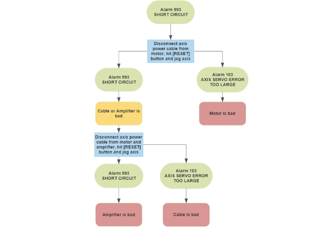
Use the following troubleshooting chart to determine whether the motor, amp, or cable is defective.

When Alarm 993 SHORT CIRCUIT occurs disconnect the axis power cable from the motor. Press [RESET] and jog the axis.

If Alarm 103 AXIS SERVO ERROR TOO LARGE occurs then the motor is defective. If another Alarm 993 SHORT CIRCUIT occurs then the cable or amp is defective.

To determine if the cable or amp is defective disconnect the axis power cable from the motor and amp. Press [RESET] and jog the axis.

If Alarm 993 SHORT CIRCUIT generates then the amplifier is defective. If Alarm 103 AXIS SERVO ERROR TOO LARGE generates the cable is defective. 

Servo Motor

Corrective Action:

Disconnect and inspect the power cable at the motor side. Verify the motor connectors are not contaminated, coolant contamination can generate drive fault alarms and damage the amplifier. Verify that the cable is connected to the corresponding amplifier as well. 

For VMC machines, new servo motor cables can be ordered to mitigate coolant intrusion. See HBC-N 03-13-25.

Measure the resistance from the pins Labeled A, B, and C at the motor connector to the chassis ground.

  • The reading must show an open circuit 
  • If the reading does not show an open circuit, the motor is at fault

Conduct a continuity test from the ground pin and chassis ground. The multimeter should beep or read less than 1 ohm resistance for continuity, otherwise then there is a short in the motor. Measure the resistance between the pins labeled A, B and C, refer to the table below for the resistance values.

NOTE: Nominal winding resistance has been added to the table for the 4-wire test method, when using a multimeter use the typical resistance value column for the expected values.

DC-1 30 Taper - Tool Carousel Motor without Brake

Important: Machines built before 3/1/2025 will have the motor without the brake.

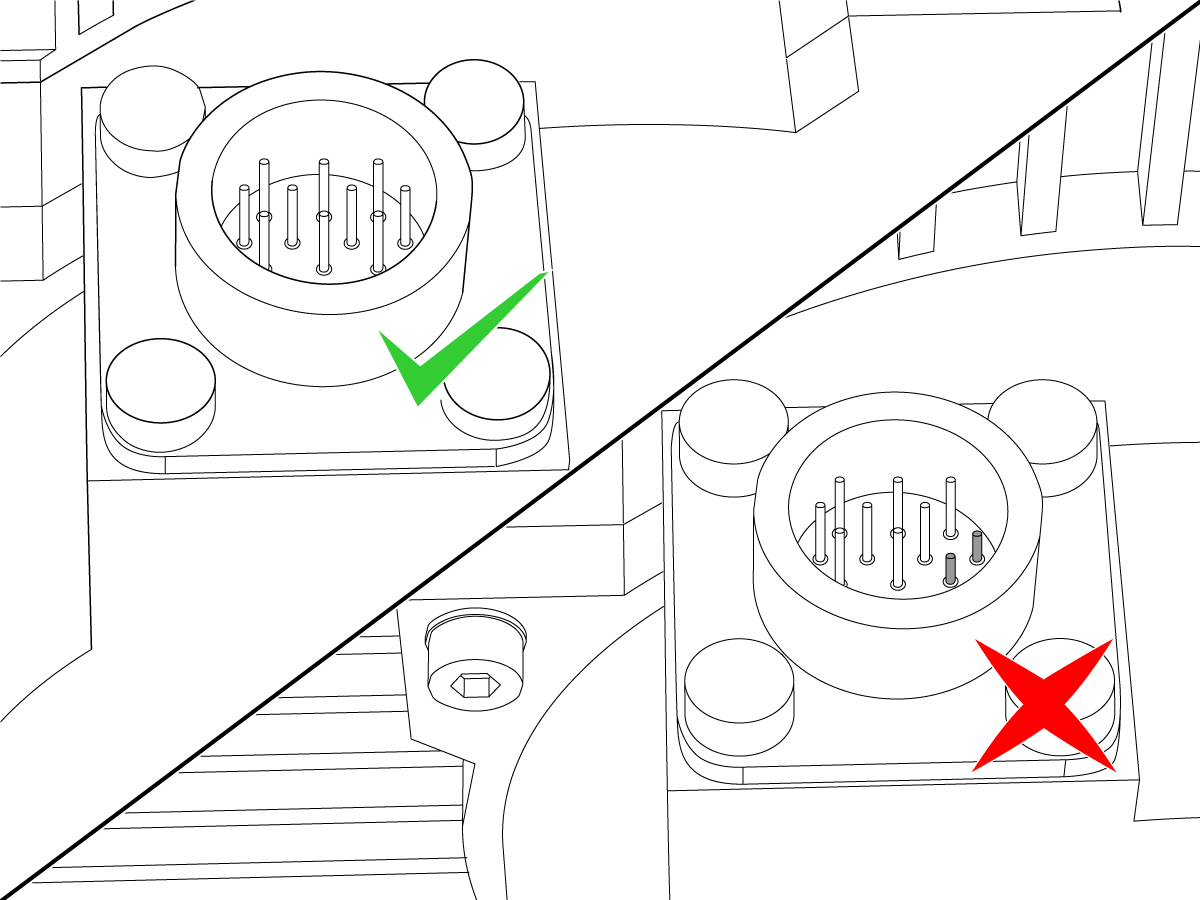
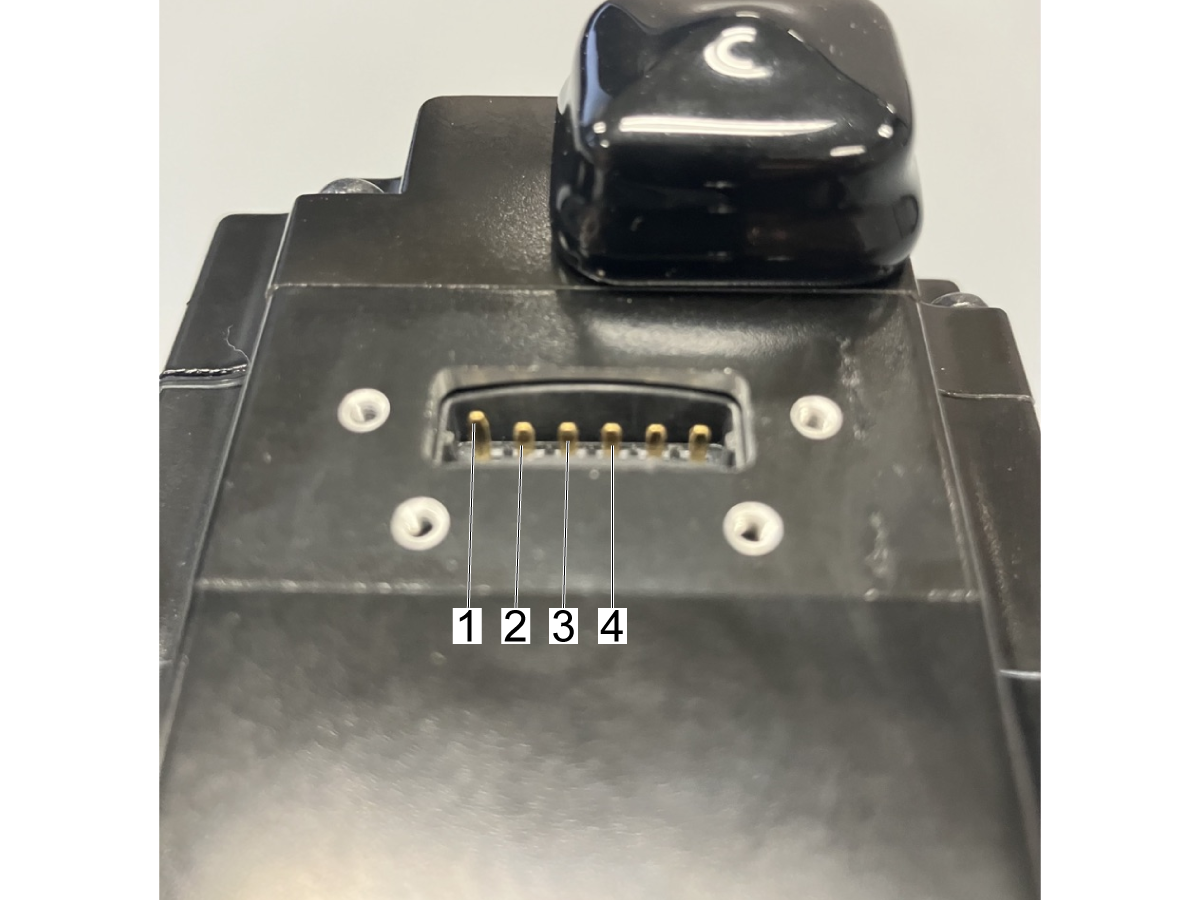
The DC-1 tool carousel motor is a sigma7 size 04 motor. The pinout for the phases looks different than other axis motors.

This image shows the pins on the motor connector:

  1. Gnd
  2. Phase A 
  3. Phase B 
  4. Phase C

NOTE: The Gnd pin [1] should be longer than the other pins as shown in the image.

NOTE: Nominal winding resistance has been added to the table for the 4-wire test method, when using a multimeter use the typical resistance value column for the expected values.

Motor type

Haas PN

MPN

Motor size

Nominal winding resistance (Ohms)

Typical DMM measured winding resistance (Ohms)

Sigma 5

62-10011/ 62-10010

SGMGV-09ADA-HA11/ SGMGV-09ADA-HA21

9

0.894

0.9

62-10013/ 62-10012

SGMGV-13ADA-HA11/ SGMGV-13ADA-HA21

13

0.554

0.6

62-10015/ 62-10014

SGMGV-20ADA-HA11/ SGMGV-20ADA-HA21

20

0.291

0.4

62-0101/ 62-10027

SGMSV-30ADV-YA11/ SGMSV-30ADA2E

30

0.179

0.3

Sigma 7

62-0127B

SGM7A-02AFK-HA21

2

6.5

6.6

62-4445 SGM7A-04A7D61 4 4.3 4.2

62-0117/ 62-0124

SGM7G-09AFA-HA11/ SGM7G-09AFA-HA21 9 0.882 1.0

62-0119/ 62-0118

SGM7G-13AFA-HA11/ SGM7G-13AFA-HA21

13

0.557

0.6

62-0120/ 62-0123

SGM7G-20AFA-HA11/ SGM7G-20AFA-HA21

20

0.286

0.4

62-0122/ 62-0121

SGM7G-30AFB-HA11/ SGM7G-30AFB-HA21

30

0.177

0.2

Mitsubishi J5

62-0138/ 62-0141

HK-ST102WK-S101212/ HK-ST102WBK-S101212

9

1.254

1.4

62-0137/ 62-0140

HK-ST172WK-S101212/ HK-ST172WBK-S101212

13

0.807

0.9

62-0142/ 62-0139

HK-ST202AWK-S101212/ HK-ST202AWBK-S101212

20

0.558

0.7

Mitsubishi J3

62-0087/ 62-0088

HF-SP81MK-S12/ HF-SP81MBK-S12

9

1.149

1.4 

62-0089/ 62-0095

HF-SP131MK-S12/ HF-SP131MBK-S12

13

0.692

0.8

62-0096/ 62-0097

HF-SP181MK-S12/ HF-SP181MBK-S12

20

0.456

0.5

Delta

62-0108/ 62-0109

ECMC-FW1308RS/ ECMC-FW1308SS

9

0.737

 0.8

Motor Brake

Corrective Action:

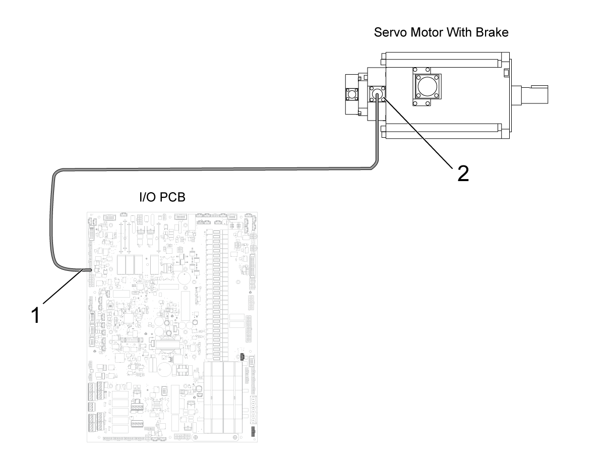
Reseat the the connection for connectors P3, P4, or P5 on the I/O PCB.

Measure the voltage across the red and black cables.

Press [EMERGENCY STOP]. There should be no voltage.

Press [RESET] to clear the alarms. The voltage should be between 20-30 VDC.

Examine the connection at the motor's brake [2] and power connectors [3] for contamination. Reseat the connections.

If no voltage is present, refer to:

  • Next Generation Control - I/O PCB -Troubleshooting Guide

Electrical Diagrams

7.5 Ballscrew Troubleshooting

Recently Updated

Ballscrew - Troubleshooting Guide


Introduction

Download and fill out the Ballscrew Inspection Report Checklist below before replacing any parts.

Ballscrew Inspection Report Checklist
Dual Ballscrew Inspection Report Checklist
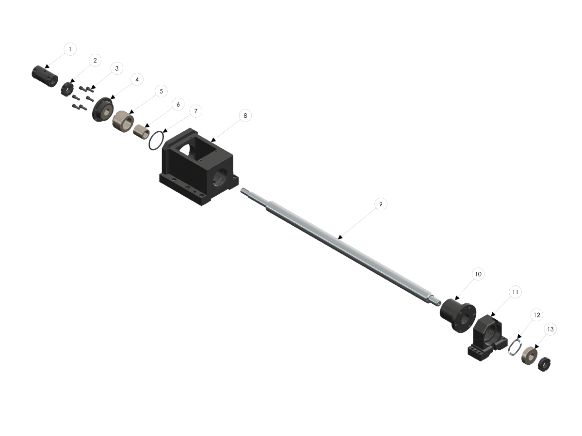
Exploded View:
 
  1. SOLID COUPLING
  2. BEARING LOCKNUT
  3. SHCS 1/4-20 X 3/4
  4. ANGULAR CONTACT BEARING
  5. BEARING FILLER
  6. SPACER
  7. O-RING
  8. MOTOR HOUSING
  9. BALL SCREW
  10. BALL NUT
  11. SUPPORT HOUSING
  12. WAVE WASHER
  13. DEEP GROOVE BEARING
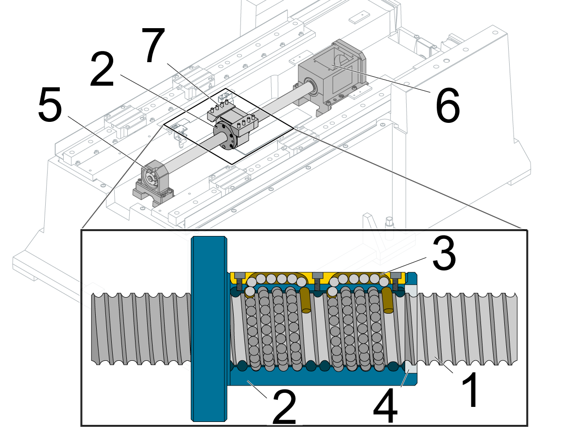
Main Components:
 
  1. Ballscrew
  2. Ballnut
  3. Balls circulate through the ballnut
  4. Wiper
  5. Support-bearing housing
  6. Motor housing
  7. Ballnut housing

Symptom Table

Symptom Possible Cause Corrective Action

Alarm 103 SERVO ERROR TOO LARGE

Alarm 104 SERVO ERROR TOO LARGE

Alarm 105 SERVO ERROR TOO LARGE

The axis motion is very rough when the axis is jogged.

There is unusual noise when the axis moves.

There is insufficient lubrication. Check the ballscrew for correct lubrication.
The ballscrew or ballnut is damaged. Check the ballscrew and ballnut for damage.
The ballscrew support bearings are damaged. Check the ballscrew support bearings for damage.
Ballscrew misalignment Ballscrew misalignment
Faulty power cable Check the Servo Motor - Troubleshooting Guide for further instructions on how to troubleshoot a faulty cable 
Misaligned ballscrew coupler

If the machine has been crashed the coupler may have moved out of alignment. Refer to the Coupler section of this procedure for more information on how to align a coupler.

NOTE: It is important to troubleshoot for a faulty cable before realigning the 

Alarm 108 AXIS SERVO OVERLOAD Ballscrew misalignment

Ballscrew misalignment

HSG-A 03/07/2023 

The cutting tool is not sharp or is damaged.  Install a new device or a new tool insert. 

The axis position does not repeat within specification.

Inconsistent accuracy, positioning, backlash.

There is insufficient lubrication, or the lubrication is contaminated. Check the ballscrew for correct lubrication.
The ballscrew or ballnut is damaged. Check the ballscrew and ballnut for damage.
The ballscrew coupling is damaged. Check the ballscrew coupling for damage.
There is excessive thermal growth. Correct your application
Dual ballscrew GM-2 is experiencing different and high loads during a movement on the X-axis and slave (F1)-axis. Machine may have moved during shipping 

Before taking any corrective action please verify the machine is experiencing the following behavior:

  • The loads on the X & F1 axis are compounding at different rates

Note: F1 axis may need to be made visible 

  • When the direction is reversed the loads switch on the two axis
  • When the E-stop is engaged the position of the two axis are not the same

If your machine is experiencing these issues please provide an inspection report and error report to Haas Service for analysis.

Please also complete the Dual Ballscrew Inspection Checklist located at the begining of this document. Further instructions will be provided after analysis. 

HSG-A 03/07/2023 

Machine was built with grade 7 ballscrews and lead compensations are not set correctly 

Ballscrew Alignment

 
Checking Ball Screw Alignment
 
  • Observe Axis Servo load while Jogging axis is question through full travel.
  • A properly aligned Ball Screw will exhibit consistent servo loads throughout its travel.

If the servo load is not consistent, the following procedure should be used to align the Ball Screw:

  • Break loose then lightly snug the following Bolts:
  1. Nut Housing to axis in question Bolts (Saddle, Table, Spindle Head, Etc.)
  2. Ballscrew to Nut Housing Bolts
  3. Bearing support Bolts
  • Jog the Axis back and forth several times, then stop the axis at the bearing support and torque all bolts that were loosened
  • Jog the Axis through its entire travel observing for consistent servo load

Lubrication

Corrective Action:

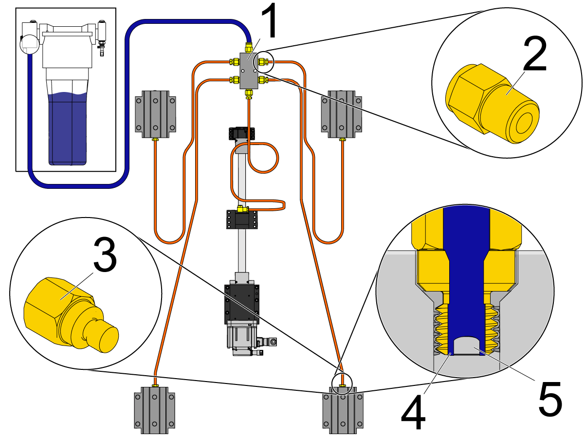
Make sure there is a light coat of oil or grease on the surface of the ballscrew. If there is not, inspect the entire lubrication system for leaks and clogs, including all tubes, hoses, and fittings. Check for leaks on each axis: A leak at one axis will cause a lack of lubrication at a different axis. Check for oil or grease puddles to help locate the source of the leak.

 Note: The Haas Liquid Grease lubrication system uses adapter fittings [2] in the axis manifolds [1]. The linear guide trucks and ballnuts use restrictor fittings [3]. The restrictor fitting has a gap [5] between the threads and the set screw [4]. This forces the manifold-fed grease to pass through the gap [4] to lubricate the axes.

Make sure the correct lubrication is used. Refer to Lubricant, Grease, and Sealant Tables for Haas Machine Components.

Ballscrew/Ballnut or Support Bearing

Corrective Action:

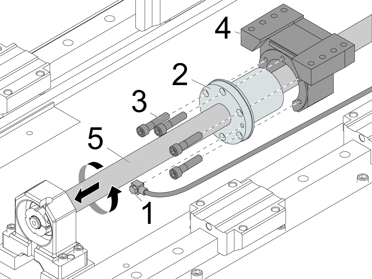
Disconnect the lubrication fitting [1] from the ballnut [2]. Remove the screws [3] that attach the ballnut [2] to the ballnut housing [4].

Ballscrew/Ballnut

Separate the ballnut [2] from the ballnut housing [4]. Rotate the ballnut [2] by hand and hold the ballscrew [5] so it does not rotate, and the ballnut [2] will move away from the ballnut housing [4].

The ballnut [2] should rotate smoothly. If there is resistance or if it binds, the ballscrew [5] and ballnut [2] are faulty.

Support Bearing

Rotate the ballscrew [5] by hand. If there is resistance or if it binds, the bearings are faulty. Remove the ballscrew [5] and check the support bearings and bearing pack to determine which components need to be replaced.

Coupler

Corrective Action:

Refer to the Ballscrew Backlash Test procedure that is appropriate for your machine.

Power off and lock out the machine. Remove the necessary covers to access the axis with the problem. Remove the axis motor cover.

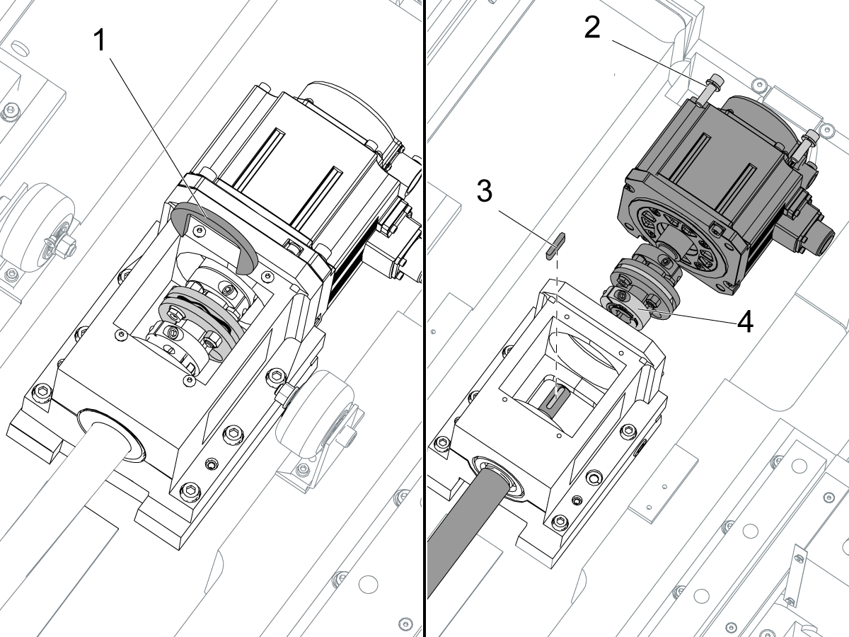
Install the coupler-installation tool [1] on the motor coupling. Turn the ballscrew so you can see the screw [4] for the motor-coupling clamp.

Remove the motor screws [2]. Loosen the screw [4] on the motor-coupling clamp. Remove the motor with the motor-coupling assembly. Remove the ballscrew key [3]. Inspect for damage or wear on the key or keyway.

 Note: If the axis motor is disconnected from the ballscrew, the grid offset and the work offset (such as G54) must be reset. Go to Axis Servo Motor - Set Grid Offset Parameter.

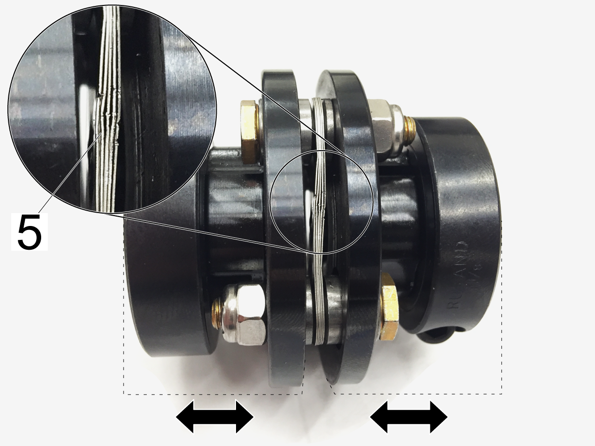
Make sure the flex pack [5] in the coupler is not damaged. It should be straight, and tightly compressed together.

 Note: If the axis motor is disconnected from the ballscrew, the grid offset and the work offset (such as G54) must be reset. Go to Axis Servo Motor - Set Grid Offset Parameter.

COUPLER ALIGNMENT:

To realign the coupler to the motor shaft install the mounting bolts loosely and float the motor in until the coupling slides from between both the motor shaft and ballscrew shaft easily. 

Torque the bolts down and verify the coupler still slides easily between the two shafts.

Torque the coupler pinch bolt to the specifications found on __________.  

Thermal Growth

Corrective Action:

You must warm up the machine axes to bring the ballscrews to a normal temperature for operation. You can warm up the machine automatically by changing certain settings: Use either Settings 158-160 or Settings 109-112. Do not use both.

  • Settings 158-160: These settings can be set from -30 to +30 and will adjust the screw thermal compensation by -30% to +30%.
  • Settings 109-112: This (Setting 109) is the number of minutes (up to 300 minutes from power-up) during which the compensations specified in Settings 110-112 are applied.

 IMPORTANT: If your application involves moving a single axis repeatedly back and forth over a small area of the ballscrew, the ballnut will heat up the ballscrew and cause thermal expansion. It will also not lubricate correctly because of the short stroke.  Every few minutes, it is necessary to move 80% to 90% of the axis travel in order to cycle the grease throughout the ballnut. This is common on smaller machines with a smaller work envelope. 

For lathes: Go to the DIAGNOSTICS screen. Check the X Axis Temp. If the measurement fluctuates or has no value, you must inspect the thermal sensor on the ballnut.

Linear Scale Compensation (LSC)

This section applies to Machines with Dual Ballscrews.

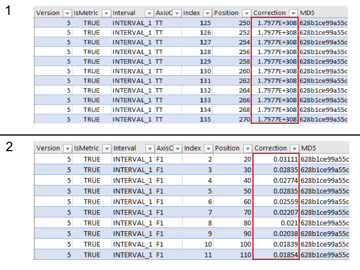
Open the LSC.LSCX file found in the Error report in a spreadsheet program.  Determine if axis compensation has been applied by looking at the correction column.

  • A value of 1.7977E+308 [1] or zero in the correction column means that there is no compensation.
  • Any other value [2] in the correction column means there is compensation.

 Note: Compensation values will vary between machines.

Recently Viewed Items

You Have No Recently Viewed Items Yet

Feedback
Haas Logo

美元价格不包括关税、报关费用、保险费、增值税及运费。
USD prices DO NOT include customs duty, customs fees, insurance, VAT, or freight.

人民币价格包含关税、报关费用、货运保险和增值税, 但不包括运费。
CNY prices include customs duty, customs fees, insurance, and VAT. DOES NOT include freight.

Haas Delivered Price

This price includes shipping cost, export and import duties, insurance, and any other expenses incurred during shipping to a location in France agreed with you as a buyer. No other mandatory costs can be added to the delivery of a Haas CNC Product.

KEEP UP WITH THE LATEST HAAS TIPS AND TECHNOLOGY...

Sign up now!   

HAAS TOOLING ACCEPTS THE FOLLOWING:

  • Service & Support
  • Owners
  • Request Service
  • Operator Manuals
  • Haas Parts
  • Rotary Repair Request
  • Pre-Install Guides
  • Shopping Tools
  • Build & Price a New Haas
  • Available Inventory
  • The Haas Price List
  • CNCA Financing
  • About Haas
  • DNSH Statement
  • Careers
  • Certifications & Safety
  • Contact Us
  • History
  • Terms & Conditions
  • Haas Tooling Terms & Conditions
  • Privacy
  • Warranty
  • Haas Community
  • Haas Certification Program
  • Haas Motorsports
  • Gene Haas Foundation
  • Haas Technical Education Community
  • Events
  • Join the Conversation
  • Facebook
  • X
  • Flickr
  • YouTube
  • LinkedIn
  • Instagram
  • TikTok
© 2025 Haas Automation, Inc – CNC Machine Tools

This site is protected by reCAPTCHA and the Google Privacy Policy and Terms of Service apply.

2800 Sturgis Rd., Oxnard, CA 93030
Toll Free: (888) 817-4446 / Fax: 805-278-8554