MyHaas Welcome,
!
Haas Tooling Guest Order History MyHaas/HaasConnect Sign In Register Haas Tooling My Account Order History Return History MyHaas/HaasConnect Sign Out Welcome, My Machines Latest Activity My Quotes My Account My Users Sign Out
Find Your Distributor
  1. Select Language
    1. English
    2. Deutsch
    3. Español - España
    4. Español - México
    5. Français
    6. Italiano
    7. Português
    8. Český
    9. Dansk
    10. Nederlands
    11. Magyar
    12. Polski
    13. Svenska
    14. Türkçe
    15. 中文
    16. Suomi
    17. Norsk
    18. الإنجليزية
    19. български
    20. Hrvatski
    21. Ελληνικά
    22. Română
    23. Slovenský
    24. Slovenščina
    25. 한국어
    26. 日本語
    27. Українська
  • machines Main Menu
    • Haas Vertical Mills Vertical Mills
      Vertical Mills
      Vertical Mills View All
      • Vertical Mills
      • VF Series
      • Universal Machines
      • VR Series
      • VP-5 Prismatic
      • Pallet-Changing VMCs
      • Mini Mills
      • Mold Machines
      • High-Speed Drill Centers
      • Drill/Tap/ Mill Series
      • Toolroom Mills
      • Compact Mills
      • Gantry Series
      • SR Sheet Routers
      • Extra-Large VMC
      • Double-Column Mills
      • Control Simulator
      • Mill Automatic Parts Loader
      • VMC/UMC Side-Loading Automatic Parts Loader
      • Compact Automatic Parts Loader
    • Product Image Multi-Axis Solutions
      Multi-Axis Solutions
      Multi-Axis Solutions View All
      • Multi-Axis Solutions
      • Y-Axis Lathes
      • 5-Axis Mills
    • Haas Lathes Lathes
      Lathes
      Lathes View All
      • Lathes
      • ST Series
      • Dual-Spindle
      • Box Way Series
      • Toolroom Lathes
      • Chucker Lathe
      • Haas Bar Feeder V2
      • Lathe Automatic Parts Loader
    • Haas Horizontal Mills Horizontal Mills
      Horizontal Mills
      Horizontal Mills View All
      • Horizontal Mills
      • 50-Taper
      • 40-Taper
    • Haas Rotaries & Indexers Rotaries & Indexers
      Rotaries & Indexers
      Rotaries & Indexers View All
      • Rotaries & Indexers
      • Rotary Tables
      • Indexers
      • 5-Axis Rotaries
      • Extra-Large Rotaries
    • Special Series
      Special Series
      Special Series View All
      • Special Series
      • EU_Series_Redirect
    • Product Image Automation Systems
      Automation Systems
      Automation Systems View All
      • Automation Systems
      • Mill Automation
      • Lathe Automation
      • Automation Models
    • Haas Drill Centers Desktop Machines
      Desktop Machines
      Desktop Machines View All
      • Desktop Machines
      • Desktop Mill
      • Desktop Lathe
    • Haas Shop Equipment Shop Equipment
      Shop Equipment
      Shop Equipment View All
      • Shop Equipment
      • Bandsaw
      • Knee Mill
      • Surface Grinder, 2550
      • Surface Grinder, 3063
      • Laser Cutting Machine
    • QUICK LINKS Special Series  Special Series 
      EU SERIES EU SERIES BUILD & PRICE | PRICE LIST BUILD & PRICE | PRICE LIST In-Stock Machines In-Stock Machines WHAT’S NEW WHAT’S NEW YOUR FIRST CNC YOUR FIRST CNC
      SHOPPING TOOLS
      • Build & Price a Haas
      • Price List
      • Available Inventory
      • CNCA Financing
      WANT TO TALK TO SOMEONE?

      A Haas Factory Outlet (HFO) can answer your questions, and walk you through your best options.

      CONTACT YOUR DISTRIBUTOR >
  • Options Main Menu
    • Product Image Spindles
      Spindles
      Spindles View All
      • Spindles
    • Product Image Tool Changers
      Tool Changers
      Tool Changers View All
      • Tool Changers
    • Product Image 4th- | 5th-Axis
      4th- | 5th-Axis
      4th- | 5th-Axis View All
      • 4th- | 5th-Axis
    • Product Image Turrets & Live Tooling
      Turrets & Live Tooling
      Turrets & Live Tooling View All
      • Turrets & Live Tooling
    • Product Image Probing
      Probing
      Probing View All
      • Probing
    • Haas Chip & Coolant Management Chip & Coolant Management
      Chip & Coolant Management
      Chip & Coolant Management View All
      • Chip & Coolant Management
    • The Haas Control The Haas Control
      The Haas Control
      The Haas Control View All
      • The Haas Control
    • Product Image Product Options
      Product Options
      Product Options View All
      • Product Options
    • Product Image Tooling & Fixturing
      Tooling & Fixturing
      Tooling & Fixturing View All
      • Tooling & Fixturing
    • Product Image Workholding
      Workholding
      Workholding View All
      • Workholding
    • Product Image 5-Axis Solutions
      5-Axis Solutions
      5-Axis Solutions View All
      • 5-Axis Solutions
      • 5 Easy Steps to 5-Axis
    • QUICK LINKS Special Series  Special Series 
      EU SERIES EU SERIES BUILD & PRICE | PRICE LIST BUILD & PRICE | PRICE LIST In-Stock Machines In-Stock Machines WHAT’S NEW WHAT’S NEW YOUR FIRST CNC YOUR FIRST CNC
      SHOPPING TOOLS
      • Build & Price a Haas
      • Price List
      • Available Inventory
      • CNCA Financing
      WANT TO TALK TO SOMEONE?

      A Haas Factory Outlet (HFO) can answer your questions, and walk you through your best options.

      CONTACT YOUR DISTRIBUTOR >
  • Why Haas Main Menu
      Discover the Haas Difference
    • Why Haas
    • MyHaas
    • Education Community
    • Industry 4.0
    • Haas Certification
    • Customer Testimonials
  • Service Main Menu
      Welcome to Haas Service
      SERVICE HOME Operator’s Manuals How-To Procedures Troubleshooting Guides Preventive Maintenance Haas Parts Haas Tooling Videos
  • Videos Main Menu
  • Main Menu
    • View All
    • View All
      • Fiber Laser
    • View All
    • View All
      • HTEC Curriculum Support
    • View All
      • Haas 10 kg Cobot Package
      • Cobot Kits
    • View All
    • View All
      • 4 - AUTOMATION SYSTEMS
      • Mill Toolholding
      • Carousel-V2
    • View All
    • View All
    • View All
      • VF-4SS
    • View All
    • QUICK LINKS Special Series  Special Series 
      EU SERIES EU SERIES BUILD & PRICE | PRICE LIST BUILD & PRICE | PRICE LIST In-Stock Machines In-Stock Machines WHAT’S NEW WHAT’S NEW YOUR FIRST CNC YOUR FIRST CNC
      SHOPPING TOOLS
      • Build & Price a Haas
      • Price List
      • Available Inventory
      • CNCA Financing
      WANT TO TALK TO SOMEONE?

      A Haas Factory Outlet (HFO) can answer your questions, and walk you through your best options.

      CONTACT YOUR DISTRIBUTOR >
  • Haas Tooling Main Menu
      Automation Accessories Shop Support Mill Toolholding Mill Cutting Tools Boring Systems Mill Workholding Lathe Toolholding Lathe Cutting Tools Lathe Workholding Package Kits ER Collets & Chucks Holemaking Threading Broaching Tombstones & Kits Manual Chucks For Milling Deburring & Abrasives Tool Presetter & Heat Shrinkers Storage & Handling Machine Maintenance Tooling Accessories Apparel & Accessories Measuring & Inspection Winner's Circle Winner's Circle Clearance Today's Hot Deals
    • Haas Tooling
    • Winner's Circle
      Winner's Circle Shop All
      • WINNERS_CIRCLE-1Y
    • Winner's Circle
      Winner's Circle Shop All
      • WC-1Y-EU
    • Today’s Hot Deals
      Today’s Hot Deals Shop All
      • Mill Toolholding
      • Mill Tooling
      • Measuring & Inspection
      • Boring Systems
      • Mill Workholding
      • Shell Mill Kits
      • Lathe Toolholding
      • Lathe Tooling
      • Lathe Workholding
      • ER Collets & Chucks
      • Holemaking
      • Threading
      • Broaching
      • Tool Storage
      • Apparel & Accessories
    • Clearance
      Clearance Shop All
    • Measuring & Inspection
      Measuring & Inspection Shop All
      • Probe Kits & Accessories
      • Edge & Center Finders
      • Comparative Measuring Gauges
      • Height Gauges
      • Calipers
      • Threaded Plug & Ring Gauges
      • Gauge Blocks
      • Pin Gauges
      • Drop Indicators
      • Dial Test Indicators
      • Bore Gauges
      • Indicator Accessories
      • V Blocks
      • Setup Blocks
      • Depth Measuring
      • Micrometers
      • Micrometer Accessories
      • Micrometer Kits
      • Bore Gauge Kits
      • Starter Kits
      • Indicator Kits
      • Caliper Kits
      • Toolholder Check Station
      • Height Setters
      • Coordinate Measuring Machines
    • Automation Accessories
      Automation Accessories Shop All
      • Cobot Kits
      • Cobot Kits
      • Protective Barriers
      • Grippers
      • Robot Cell Accessories
    • Shop Support
      Shop Support Shop All
      • Air Compressors
      • Laser Marking Machines
      • Bandsaw Blades
      • Bandsaw Accessories
      • Surface Grinding Wheels
      • Shop Equipment Accessories
    • Mill Toolholding
      Mill Toolholding Shop All
      • End Mill Holders
      • Shell Mill Holders
      • Shrink Fit Holders
      • ER Collet Chucks
      • Milling Chucks & Collets
      • NC Drilling Chucks
      • Pull Studs / Retention Knobs
      • Rotary Tool Holder & Tool Chuck Kits
      • Hydraulic Milling Chucks & Collets
      • Toolholder Attachments & Wrenches
      • Mill Broaching Holders
    • Mill Tooling
      Mill Tooling Shop All
      • Shell Mill Bodies
      • Milling Inserts
      • End Mills
      • Chamfer Mills & Inserts
      • Indexable End Mill Bodies
      • Ball End Mills
      • Chamfer End Mills
      • Roughing End Mills
      • Indexable Ball End Mills & Inserts
      • Shell Mill Kits
      • Chamfer Mill Kits
      • Indexable End Mill Kits
      • Dovetail Cutters
      • Indexable Dovetail Cutters
      • Engraving End Mills
      • Rotary Burrs / Die Grinding Bits
      • Keyseat Cutters
      • Corner Rounding End Mills
      • Slot Mill Bodies
      • CNC Router Bits For Wood
    • Boring Systems
      Boring Systems Shop All
      • Boring Heads & Cartridges
      • Boring Holders & Extensions
    • Mill Workholding
      Mill Workholding Shop All
      • Fixed-Jaw Vises
      • Self-Centering Vises
      • Adapter Plates
      • Vise Jaws
      • Vise Mounts & Fixtures
      • Vise Kits
      • Vise Parallels
      • Rotary Vise Kits
      • Fixture Clamps & Rails
      • Automated Workholding Kits
      • Tooling Fixture Subplates
      • Toolmakers' Vises
      • Clamp Force Gauges
      • Collet Fixtures
      • Angle Plates
    • Lathe Toolholding
      Lathe Toolholding Shop All
      • TL & CL Static Turning Holders
      • BOT Static Turning Holders
      • BMT Static Turning Holders
      • Live / Driven Turning Holders
      • Turning Holder Reduction Sleeves / Bushings
      • VDI Static Turning Holders
      • Turning Holder Accessories
    • Lathe Tooling
      Lathe Tooling Shop All
      • Cut-Off Tool Blocks & Blades
      • Cut-Off Tooling Kits
      • Turning Inserts
      • Grooving & Cut-Off Tools
      • Internal (ID) Grooving & Threading Tools
      • Threading Inserts
      • Threading Tools
      • Boring Bars / Internal (ID) Turning Tools
      • External (OD) Turning Tools
      • Cermet Turning Inserts
      • CBN Turning Inserts
      • Haas Notch Grooving & Threading Inserts
      • Haas Notch Grooving & Threading Tools
      • Micro Turning Tools
      • Desktop Lathe Tools
    • Lathe Workholding
      Lathe Workholding Shop All
      • Live Centers
      • Spindle Reduction Sleeves / Liners
      • Quick-Change Collets
      • Quick-Change Collet Chucks
      • 5C Collets
      • 5C Collet Sets
      • Lathe Jaw Boring Rings
      • Lathe Jaws
      • Bar Pullers
      • Scroll Chucks
      • Guide Pins
      • Collet Accessories
    • Package Kits
      Package Kits Shop All
      • Chip Clearing Fan Kits
      • Cutting Tool Kits
      • Indexable End Mill Kits
      • Cut-Off Tool Block & Blade Kits
      • Drill & Tap Kits
      • Indexable Drilling Kits
      • Shell Mill Kits
      • Chamfer Mill Kits
      • Rotary Tool Holder & Tool Chuck Kits
      • Lathe Starter Kits
      • Workholding Kits
      • Rotary Vise Kits
      • Vise Kits
      • 3-Jaw Chuck Kits for Mills
      • Tombstone Kits
      • Reduction Sleeve Kits
      • Automated Workholding Kits
      • Measuring & Inspection Kits
      • Starter Kits
      • Bore Gauge Kits
      • Caliper Kits
      • Indicator Kits
      • Micrometer Kits
    • ER Collets & Chucks
      ER Collets & Chucks Shop All
      • ER Straight-Bore Collets
      • ER Sealed Collets
      • ER Tap Collets
      • ER Collet Sets & Accessories
      • ER Collet Chucks
      • Straight Shank ER Collet Chucks
      • Straight Shank Keyless NC Drilling Chucks
    • Holemaking
      Holemaking Shop All
      • Carbide Drills
      • Indexable Drill Bodies
      • Indexable Drill Inserts
      • Modular Drill Bodies
      • Modular Drill Heads
      • Cobalt Drills & Sets
      • Center Drills
      • Reamers
      • Indexable Drilling Kits
      • Spot Drills
      • Spade Drill Bodies
      • Spade Drill Inserts
      • Countersinks
    • Threading
      Threading Shop All
      • Taps
      • Threading Inserts
      • Threading Tools
      • Thread Mills
      • Pipe Taps
      • Drill Tap Kits
    • Broaching
      Broaching Shop All
      • Broaching Tools
      • Broaching Inserts
    • Tombstones
      Tombstones Shop All
      • Tombstones
      • Tombstone Kits
      • Vise Cluster Towers
    • Manual Chucks For Milling
      Manual Chucks For Milling Shop All
      • 3-Jaw Chucks & Mounts for Mills
    • Deburring & Abrasives
      Deburring & Abrasives Shop All
      • Abrasive Pads
      • Deburr Tools
      • Deburr Wheels
      • Abrasive Sheets & Rolls
      • Sharpening / Lapping Stones
    • Tool Presetter & Heat Shrinkers
      Tool Presetter & Heat Shrinkers Shop All
      • Tool Presetting Machines
      • Shrink Fit Machines
    • Tool Storage
      Tool Storage Shop All
      • Tool Carts
      • Tool Tray
      • Tool Bags
    • Machine Maintenance
      Machine Maintenance Shop All
      • Spindle Test Bars
      • Levels
      • Refractometers
      • Machine Additives & Supplies
      • Machine Accessories
      • Machine Maintenance Kits
    • Tooling Accessories
      Tooling Accessories Shop All

      • Spindle & Toolholder Taper Cleaners
      • Haas Shop Lift
      • Toolholder Fixtures
      • CNC Chip Clearing Fans
      • Hammers & Mallets
      • Anti-Fatigue Mats
      • Layout Tools
      • Wrenches
      • Magnetic Tools
      • Torque Screwdrivers
      • Hand Cutting Tools
      • Shop Stools
      • Lifting Magnets
      • Safety Apparel
      • Cutting Tool Sharpeners
    • Apparel & Accessories
      Apparel & Accessories Shop All
      • Accessories
      • Apparel
    • HAAS TOOLING QUICK LINKS
      NEW PRODUCTS NEW PRODUCTS NEW PRODUCTS NEW PRODUCTS
      MOST POPULAR MOST POPULAR
      TOOLING PROMOS TOOLING PROMOS
      FINANCING & OPEN TERMS FINANCING & OPEN TERMS PAY BY INVOICE PAY BY INVOICE
      FAQs FAQs
      KITS CREATED FOR YOU KITS CREATED FOR YOU
  • Haas Service Parts Main Menu
      Automatic Pallet Changer Lathe Turret Tool Changer Chip Management Coolant Counterbalance Electrical Cabinet Enclosure Hydraulics Lubrication Maintenance Pendant Probing Rotary Spindle Tailstock
    • Haas Service Parts
    • Automatic Pallet Changer
      Automatic Pallet Changer Shop All
      • HMC - Automatic Pallet Changer
      • VMC - Automatic Pallet Changer
    • Lathe Turret
      Lathe Turret Shop All
      • Lathe - Turret
      • Live Tooling
    • Tool Changer
      Tool Changer Shop All
      • Side Mount
      • Umbrella
    • Chip Management
      Chip Management Shop All
      • Multi Auger
      • Single Auger
    • Coolant
      Coolant Shop All
      • Auxiliary Filter
      • HPC-300 (Lathe)
      • HPC-1000 (Lathe)
      • Oil Skimmer
      • Standard Coolant
      • TSC-300 (Mill)
      • TSC-1000 (Mill)
      • Coolant Refill
      • Loc-Line
    • Counterbalance
      Counterbalance Shop All
      • Charge & Discharge Hose
    • Electrical Cabinet
      Electrical Cabinet Shop All
      • Fans
      • Filters
      • Upgrade Kits
    • Enclosure
      Enclosure Shop All
      • Accessories
      • Air Nozzle
      • Decals
      • Door Bumpers
      • Lighting
      • Windows, Gaskets, & Weather Strip
      • Chip & Coolant Management
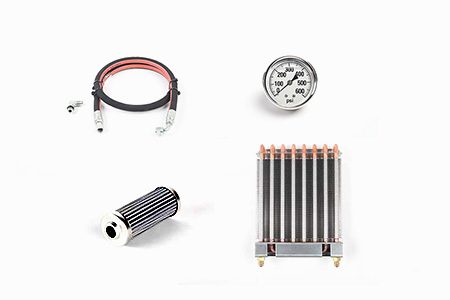
    • Hydraulics
      Hydraulics Shop All
      • Filters
      • Gauges
      • Heat Exchanger
      • Hoses
    • Lubrication
      Lubrication Shop All
      • Bijur Mechanical Lubrication
      • Minimum Lubrication
    • Maintenance
      Maintenance Shop All
      • Grease, Oil, & Sealants
    • Pendant
      Pendant Shop All
      • Floppy Disk & USB
      • Keypad
      • Keys
      • Lens
      • Gaskets & Seals
    • Probing
      Probing Shop All
      • Mill Probing
      • Lathe Tool Presetter
    • Rotary
      Rotary Shop All
      • Rotary Gaskets & Seals
    • Spindles
      Spindles Shop All
      • Couplings
      • Gaskets & Seals
      • Spindle Motor Drive
      • Gearbox Drive
      • Tool Release Piston
    • Tailstock
      Tailstock Shop All
      • Handles
×

Search Results

Web Pages

Images

    • <
    • 1
    • >
MyHaas Welcome,
!
Haas Tooling Guest Order History MyHaas/HaasConnect Sign In Register Haas Tooling My Account Order History Return History MyHaas/HaasConnect Sign Out Welcome, My Machines Latest Activity My Quotes My Account My Users Sign Out
Find Your Distributor
  1. Select Language
    1. English
    2. Deutsch
    3. Español - España
    4. Español - México
    5. Français
    6. Italiano
    7. Português
    8. Český
    9. Dansk
    10. Nederlands
    11. Magyar
    12. Polski
    13. Svenska
    14. Türkçe
    15. 中文
    16. Suomi
    17. Norsk
    18. الإنجليزية
    19. български
    20. Hrvatski
    21. Ελληνικά
    22. Română
    23. Slovenský
    24. Slovenščina
    25. 한국어
    26. 日本語
    27. Українська
×

Search Results

Web Pages

Images

    • <
    • 1
    • >

7 - Rotary - Programming

Rotary/Tailstock - Operator's Manual Supplement


  • 1 - Rotary - Introduction
  • 2 - Rotary - Legal Information
  • 3 - Rotary - Installation
  • 4 - Rotary - Operation
  • 5 - Rotary - MRZP
  • 6 - Rotary - 5-Axis Models
  • 7 - Rotary - Programming
  • 8 - Rotary - G-Codes
  • 9 - Rotary - Parameters
  • 10 - Rotary - Maintenance
  • 11 - Rotary - Workholding
  • 12 - Tailstock - Operation/Setup

Go To :

  • 7.1 Control Box Programming
  • 7.2 RS-232 Interface
  • 7.3 Program Functions
  • 7.4 Simultaneous Rotation & Milling
  • 7.5 Programming Examples

Introduction

This section covers manual input of your program. Unless you up-load a program from a computer or CNC Mill using the RS-232 serial port (refer to “The RS-232 Interface” on page 5), programming is done through the keypad on the front panel. The buttons on the right column of the keypad are used for program control.

NOTE: Always press and immediately release a button. Pushing and holding down a button causes the button to repeat; however, this is useful when scrolling through a program. Some buttons have more than one function depending on the mode.

Press MODE/RUN PROG to select between the Program mode and Run mode. The display flashes on and off when in Program mode and remains steady when in Run mode.

In Program mode, you enter commands into memory as steps.


Step Number Step Size Feed Rate Loop Count G Code
1 90.000 80 01 91
2 -30.000 05 01 91
3 0 80 01 99
Through
99 0 80 01 99

Pushing DISPLAY SCAN moves the window to the right. Pushing STEP SCAN up or down arrow moves the window up or down.

Putting a Program into Memory

NOTE: All data is automatically stored in memory when you press a control button.

Programming begins with making sure that the Servo Control is in Program mode and at step number 01. To do this:

  1. Press MODE/RUN PROG while the unit is not in motion.
    One of the display fields blinks, indicating you are in Program mode.

  2. Push and hold CLEAR/ZERO SET for five seconds.
    You have cleared the memory. You are at step 01 and ready to begin programming, 01 000.000 is displayed. The memory does not have to be cleared each time data is entered or changed. You can change data in the program simply by writing new data over old.

  3. You can store (7) programs in a single-axis control (numbered 0-6). To access a program, press - (minus) while showing a G-code.

    The display changes to: Prog n.

  4. Press a number key to select a new program, and then press MODE/RUN PROG to return to Run mode or CYCLE START to continue in Program mode.

    Each one of the possible 99 steps in a program must contain a G-code and one of these:

    a)Step size or position command shown as a number with possible minus sign.
    b) Feed rate shown with a preceding F.
    c) Loop count shown with a preceding L.
    d) Subroutine destination with a preceding Loc
    .
  5. To display the additional codes associated with a step, press DISPLAY SCAN.

    Example lines of code:
    S135.000 G91
    F0 40.000 L001

  6. Some entries are not allowed for particular G-codes, and either cannot be entered or are ignored. Most steps are incremental position commands and this is the default G91.

  7. G86, G87, G89, G92, and G93 should be used with the CNC relay function disabled (Parameter 1 = 2). Enter your step size in degrees to three decimal places. You must always enter the decimal places, even if they are zero. Enter a minus sign (-) for opposite rotation. To edit a feedrate or loop count, push DISPLAY SCAN to view the entry and input the data.

    NOTE: Program steps N2 through N99 are set to the end code when the memory is cleared. This means that it is not necessary to enter G99. If you are removing steps from an existing program, make sure that you have entered a G99 after the last step.

  8. If you are programming for a part that does not use feed rates or loop counts, simply push the down arrow to go to the next step. Insert the G-code and step size and move on to the next step. The step automatically is set to the fastest feed rate and a loop count of one.

    NOTE: The HRT320FB does not use a feedrate; it indexes at maximum speed.

  9. If you enter an incorrect number, or one that is out of limits, the Servo Control displays: Error. Press CLEAR/ZERO SET and enter the correct number.

  10. If you entered a valid number and an Error still appears, check Parameter 7 (Memory Protect). When the last step is entered, an end code must be in the following step.

Selecting a Stored Program

To select a stored program:

Press MODE/RUN PROG.

One of the display fields blinks, indicating you are in Program mode.

With a G-code number field flashing, press - (minus).

This changes the display to: Prog n.

Press a number to select a stored or new program.

Press MODE/RUN PROG.

The control returns to Run mode.

Or, press CYCLE START to edit the selected program.

The control continues with Program mode.

Clearing a Program

To clear a program (not including parameters):

Press MODE/RUN PROG until the display flashes on and off.

This is Program mode.

Press and hold CLEAR/ZERO SET for three seconds.

The display cycles through all 99 steps and sets all but the first to G99. The first step is set to G91, step size 0, maximum feed rate, and a loop count of 1.

Entering a Step

To enter a step into Servo Control memory:

Press MODE/RUN PROG.

This puts the Servo Control in Program mode. The display begins blinking and shows a step size.

If necessary, press and hold CLEAR/ZERO SET for 3 seconds to clear the last program.

To enter a 45° step, type 45000.

The display shows: N01 S45.000 G91, and on a line below, F60.272 L0001 (the value is the max speed for the rotary table).

Press STEP SCAN down arrow.

This stores the 45° step.

Enter a feed rate of 20° per second, by typing 20000.

The display shows 01 F 20.000.

Press MODE/RUN PROG to return the control to Run mode.

Start the 45° step by pressing CYCLE START.

The table moves to the new position.

Inserting A Line

To insert a new step into a program:

Press MODE/RUN PROG until the display flashes on and off.

This is Program mode.

Press and hold CYCLE START for three seconds while in Program mode.

This moves the current step and all following steps down, and inserts a new step with default values.

note: Subroutine jumps must be renumbered.

Deleting a Line

To delete a step from a program:

Press MODE/RUN PROG until display flashes on and off.

This is Program mode.

Press and hold ZERO RETURN for three seconds.

All the following steps move up by one.

note: Subroutine jumps must be renumbered.

The RS-232 Interface

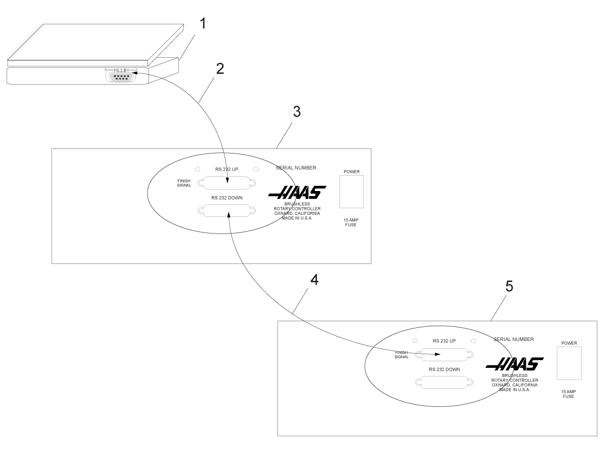
There are two connectors used for the RS-232 interface; one each of male and female DB-25 connectors. To connect multiple Servo Controls, connect the cable from the computer to the female connector. Another cable can connect the first Servo Control to the second by connecting the male connector of the first box to the female connector of the second. You can connect up to nine controls in this way. The RS-232 connector on the Servo Control is used to load programs.

The RS-232 connector on the back of most personal computers is a male DB-9, so only one type of cable is required for connection to the control, or between controls. This cable must be a DB-25 male on one end and a DB-9 female on the other. Pins 1, 2, 3, 4, 5, 6, 7, 8, and 9 must be wired one-to-one. It cannot be a Null Modem cable, which inverts pins 2 and 3. To check cable type, use a cable tester to check that communication lines are correct.

The control is DCE (Data Communication Equipment), which means that it transmits on the RXD line (pin 3) and receives on the TXD line (pin 2). The RS-232 connector on most PCs is wired for DTE (Data Terminal Equipment), so no special jumpers should be required.

PC Parameter Value
Stop Bits 2
Parity Even
Baud Rate 9600
Data Bits 7

RS-232 Daisy Chain Two Servo Controllers for TRT:

[1] PC with RS-232 DB-9 Connector

[2] RS-232 Cable DB-9 to DB-25 straight through

[3] Servo Control A-Axis

[4] RS-232 Cable DB-25 to DB-25 straight through

[5] Servo Control B-Axis

The RS-232 DOWN (out line) DB-25 connector is used when multiple controls are used. The first control’s RS-232 DOWN (out line) connector goes to the second controller’s RS-232 UP (in line) connector, etc.

If Parameter 33 is 0, the CTS line can still be used to synchronize output. When more than one Haas rotary control is daisy-chained, data sent from the PC goes to all of the controls at the same time. That is why an axis selection code (Parameter 21) is required. Data sent back to the PC from the controls is programmed together using digital logic OR gates (OR-ed) so that, if more than one box is transmitting, the data will be garbled. Therefore, the axis selection code must be unique for each controller. The serial interface may be used in either a remote command mode or as an upload/download path.

Upload and Download

The serial interface may be used to upload or download a program. All data is sent and received in ASCII code. Lines sent by the Servo Control are terminated by a carriage return (CR) and line feed (LF). Lines sent to the Servo Control may contain a LF, but it is ignored and the lines are terminated by a CR.

Programs sent or received by the controller have the following format:

%
N01 G91 X045.000 F080.000 L002
N02 G90 X000.000 Y045.000 
F080.000
N03 G98 F050.000 L013
N04 G96 P02
N05 G99
%

The Servo Control inserts steps and re-numbers all required data. The P code is the destination of a subroutine jump for G96.

The % must be found before the Servo Control processes any input and it always begins output with a %. The N-Code and G-code are found on all lines and the remaining codes are present as required by the G-code. The N-Code is the same as the step number display in the controller. All N-Codes must be continuous starting from 1. The Servo Control always ends output with a % and inputs to it is terminated by a %, N99 or G99. Spaces are only allowed where shown.

The Servo Control displays SEnding as a program is sent. The Servo Control displays LoAding as a program is received. In each case, the line number changes as the information is sent or received. An error message is displayed if bad information was sent, and the display indicates the last line received. If an error occurs, make sure that the letter O was not inadvertently used in the program instead of a zero. 

When an RS-232 interface is used, it is recommended that the programs be written in Windows Notepad, or another ASCII program. Word processing programs, such as Word, are not recommended, as they will insert extra, unnecessary information.

Upload/Download functions do not need an axis select code, as they are manually initiated by an operator at the front panel. However, if the select code (Parameter 21) is not zero, an attempt to send a program to the control will fail, as the lines do not begin with the correct axis select code.

Upload or download is started from Program mode with the G-code displayed. To start an upload or download:

  1. Press - (minus) while the G-code is displayed and blinking.

    Prog n is displayed, where n is the currently selected program number.

  2. Select a different program by pressing a number key, then press CYCLE START to return to Program mode or MODE/RUN PROG to return to Run mode, or press - (minus) again and the display shows: SEnd n ,where n is the currently selected program number.

  3. Select a different program by pressing a number key and then CYCLE START to begin sending that selected program, or press - (minus) again and the display shows: rEcE n ,where n is the currently selected program number.

  4. Select a different program by pressing a number key and then Start to begin receiving that selected program, or press the minus (-) key again to return the display to Program mode.

  5. Both uploading and downloading can be terminated by pressing CLEAR/ZERO SET.

RS-232 Remote Command Mode

Parameter 21 cannot be zero for the remote command mode to operate. The Servo Control looks for an axis select code defined by this parameter.

The Servo Control must also be in RUN mode to respond to the interface. Since the control powers-on in RUN mode, unattended remote operation is possible.Commands are sent to the Servo Control in ASCII code and terminated by a carriage return (CR).

All commands, except for the B command, must be preceded by the numeric code for an axis (U, V, W, X, Y, Z). Refer to “Parameter 21 Settings” on page 5.The B command does not require the select code, since it is used to activate all axes simultaneously. The ASCII codes used to command the control follow:

RS-232 Single Axis Commands

The following are the RS-232 commands, where x is the selected axis designated by Parameter 21 (cap U, V, W, X, Y, or Z):

ASCII Command Function
xSnn.nn Specify step size nn.nn or absolute position.
xFnn.nn Specify feed rate nn.nn in units/second.
xGnn Specify Gnn code.
xLnnn Specify loop count nnn.
xP Specify servo status or position. This command causes addressed Servo Control to respond with servo position if normal operation is possible, or otherwise with the servo status.
xB Begin programmed step on x-axis.
B Begin programmed step on all axes at once.
xH Return to Home position or use home offset.
xC Clear Servo Control position to zero and establish zero.
xO Turn Servo Control on.
xE Turn Servo Control off.

Sample Remote Program

The following is a transmitted program for the W-Axis. Set Parameter 21 = 3 (W-Axis). Send the following:

WS180.000 (Steps)
WF100.000 (Feed)
WG91 (Increment)
WB (Begin)

RS-232 Responses

The xP command, where x is the selected axis designated by Parameter 21 (cap U, V, W, X, Y, or Z), is presently the only command that responds with data. It returns a single line consisting of:

Response Meaning
xnnn.nnn Servo Control at standstill at position nnn.nnn
xnnn.nnnR Servo in motion past position nnn.nnn
xOn Servo is off with reason n
xLn Servo Home position lost with reason n

Program Functions

These areas have specific control programs:

  • Absolute/Incremental Motion
  • Auto Continue Control
  • Continuous Motion
  • Loop Counts
  • Circle Division
  • Delay Code (G97)
  • Feedrates
  • Subroutines (G96)

Absolute / Incremental Motion

To use absolute or incremental motion:

Use G90 for absolute positions and G91 for incremental positions. G90 is the only command allowing absolute positioning.

NOTE: G91 is the default value and provides incremental motion.

Use G28 and G88 for a programmed home command. The entered feedrate is used to return to the zero position.

Auto Continue Control

To control the auto continue mode:

  1. Set Parameter 10 to 2.
    The control executes the entire program and stops when G99 is reached.
  2. Press and hold CYCLE START until the current step is finished to stop the program.
  3. To restart the program, press CYCLE START again.

Continuous Motion

To start continuous motion:

G33 uses remote CYCLE START to start continuous motion.

When an M-Fin signal from the CNC control is connected to the Remote CYCLE START, and an arbitrary feed rate is entered in the feed rate field for the G33 step, rotary motion continues until the M-Fin signal is released.

Set step size to 1.000 for G33 clockwise motion. Set step size to –1.000 for G33 counter-clockwise motion.

The loop count is set to 1.

Loop Counts

Loop Counts allows a step to repeat up to 999 times, before going on to the next step. The loop count is an L followed by a value between 1 and 999. In Run mode, it displays the remaining loop counts for the selected step. It is also used in conjunction with the Circle Division function to enter the number of divisions in the circle from 2 to 999. The Loop Count specifies the number of times to repeat a subroutine, when used with G96.

Delay Code (G97)

G97 is used to program a pause (dwell) in a program. For example, programming a G97 and setting L = 10 produces a 1 second dwell. G97 does not pulse the CNC relay at step completion.

Circle Division

Circle division is selected with a G98 (or G85 for TRT units). The L defines how many equal parts a circle is divided into. After the L count steps, the unit is in the same position it started from. Circle division is only available in the circular modes (i.e., Parameter 12 = 0, 5, or 6).

Feedrate Programming

The feedrate display ranges between 00.001 and the maximum for the rotary unit (see table). The feedrate value is preceded by an F and displays the feedrate used for the selected step. The feedrate corresponds to degrees rotated per second.

For example:A feedrate of 80.000 means the platter rotates 80° in one second.

When the Servo Control is in Stop mode, press - to change the feed rate value in the program without modifying the program or any parameters. This is the Feed Rate Override mode.

Press - until the desired feed rate value (50, 75 or 100%), e.g., OVR:75%, is indicated in the lower, right corner of the display.

Model Maximum Feedrate
HA5C 410.000
HRT160 130.000
HRT210 100.00
HRT310 75.000
HRT450 50.000

Subroutines (G96)

Subroutines allow repetition of a sequence up to 999 times. To call a subroutine, enter G96. After entering 96 move the blinking display 00 preceded by Step# registered to enter the step to jump to. The control jumps to the step called out in the Step# register, when the program reaches the G96 step. The control executes that step and the ones following until a G95 or G99 is found. The program then jumps back to the step following the G96.

A subroutine is repeated by using the loop count of a G96. To end the subroutine, insert either a G95 or G99 after the last step. A subroutine call is not considered a step by itself, since it executes itself and the first step of the subroutine.

NOTE: Nesting is not permitted.

Simultaneous Rotation and Milling

G94 is used to perform simultaneous milling. The relay is pulsed at the beginning of the step so that the CNC mill goes to the next block. The Servo Control then executes the L steps without waiting for start commands. Normally, the L count on the G94 is set to 1 and that step is followed by a step that is run simultaneous with a CNC mill.

Spiral Milling (HRT & HA5C)

Spiral milling is coordinated movement of the rotary unit and the mill axis. Simultaneous rotation and milling allows machining of cams, spiral, and angular cuts. Use a G94 in the control and add rotation and feed rate. The control executes G94 (signals mill to proceed) and the following step(s) as one. If more than one step is required, use an L command. In order to spiral mill, the mill feed rate must be calculated so the rotary unit and the mill axis stop at the same time.

In order to calculate the mill feed rate, the following information needs to be addressed:

  • The angular rotation of the spindle (this is described in the part drawing).
  • A feed rate for the spindle (arbitrarily select a reasonable one, for example, five degrees (5°) per second).
  • The distance you wish to travel on X-axis (see part drawing).

For example, to mill a spiral that is 72° of rotation and move 1.500" on the X-axis at the same time:

  1. Compute the amount of time it takes the rotary unit to rotate through the angle # of degrees / (feed rate of spindle) = time to index 72 degrees / 5° per second = 14.40 seconds for unit to rotate.

  2. Compute the mill feed rate that moves the X distance in 14.40 seconds (length to travel in inches/# of seconds of rotation) x 60 seconds = mill feed rate in inches per minute. 1.500 inches/14.4 seconds = 0.1042 inches per second x 60 = 6.25 inches per minute.

Therefore, if the indexer is set to move 72° at a feed rate of 5° per second, program the mill to travel 1.500 inches with a feed rate of 6.25 inches per minute for the spiral to be generated.

The program for the Servo Control is as follows:

STEP STEP SIZE FEED RATE LOOP COUNT G CODE
01 0 080.000 (HRT) 1 G94
02 [72000] [5.000] 1 G91
03 0 080.000 (HRT) 1 G88
04 0 080.000 (HRT) 1 G99

The mill program for this example looks like this:

N1 G00 G91 (rapid in incremental mode) ;
N2 G01 F10. Z-1.0 (feed down in Z-axis) ;
N3 M21 (to start indexing program above at step one) ;
N4 X-1.5 F6.25 (index head and mill move at same time here) ;
N5 G00 Z1.0 (rapid back in Z-axis) ;
N6 M21 (return indexer Home at step three) ;
N7 M30 ;

Possible Timing Issue

When the Servo Control executes a G94, a 250 millisecond delay is required before starting the next step. This may cause the mill axis to move before the table rotates, leaving a flat spot in the cut. If this is a problem, add a 0 to 250 milliseconds dwell (G04) after the M-Code in the mill program to prevent mill axis movement.

By adding a dwell, the rotary unit and the mill start moving at the same time. It may be necessary to alter the feed rate on the mill to avoid timing issues at the end of the spiral. Do not adjust the feed rate on the rotary control; use the mill with its finer feed rate adjustment. If the undercut appears to be in the X-Axis direction, increase the mill feed rate by 0.1. If the undercut appears in the radial direction, decrease the mill feed rate.

If timing is off by several seconds, such that the mill completes its movement before the rotary and there are several spiral moves one after another (as in retracing a spiral cut), the mill may stop. The reason is the mill sends a cycle start signal (for next cut) to the rotary control before it has completed its first move, but the rotary control does not accept another start command until it finishes the first.

Check timing calculations when doing multiple moves. A way to verify this is to Single Block the control, allowing five seconds between steps. If the program runs successfully in Single Block and not in the continuous mode, the timing is off.

Programming Examples

The following sections contain examples of Servo Control programming:

Example 1 - Index the platter 90°.

Example 2 - Index the platter 90° (Example 1, Steps 1-8), rotate at 5 °/sec (F5) in the opposite direction for 10.25° and then return home.

Example 3 - Drill a four-hole pattern and then a five-hole pattern on the same part.

Example 4 - Index 90.12°, start a seven-hole bolt pattern, and then return to the zero position.

Example 5 - Index 90°, slow feed for 15°, repeat this pattern three times, and return home.

Example 6 - Index 15°, 20°, 25°, and 30° in sequence, four times, and then drill a five-hole bolt pattern.

Programming Example 1

To index the platter 90°:

  1. Turn on power by pressing 1 on the rear panel POWER switch.
  2. Press CYCLE START.
  3. Press ZERO RETURN.
  4. Press MODE/RUN PROG and release.
    Display blinks.
  5. Press and hold CLEAR/ZERO SET for five seconds.
    The display shows 01 000.000.
  6. Type 90000 on the key pad.
  7. Press MODE/RUN PROG.
    The display stops blinking.
  8. Press CYCLE START to index.

Programming Example 2

To index the platter 90° (Example 1, Steps 1-8), rotate at 5 °/sec (F5) in the opposite direction for 10.25°, and then return home:

  1. Run Programming Example 1, on page 5.
  2. Press MODE/RUN PROG and release.
    The display blinks.
  3. Press the STEP SCAN down arrow twice. You should be on program step 02.
  4. Type 91 on the key pad. Use CLEAR/ZERO SET to erase mistakes.
  5. Press DISPLAY SCAN.
  6. Type -10250 on the keypad.
  7. Press the STEP SCAN down arrow.
    The Servo Control is now on the feed display.
  8. Type 5000 on the keypad.
  9. Press the STEP SCAN down arrow.
    The control is now on step 03.
  10. Type 88 on the keypad.
  11. Press the STEP SCAN up arrow (4) times. The control is now on step 01.
  12. Press MODE/RUN PROG.
    The display stops blinking.
  13. Press Cycle Start (3) times. The unit indexes 90 degrees (90°), slow feeds in the opposite direction for 10.25 degrees (10.25°), then returns home.

Programming Example 3

This example shows the program as you would enter it into the Servo Control. Be sure to clear out the memory before you enter the program.

To drill a four-hole pattern, and then a five-hole pattern on the same part:

1

Enter these steps into the Servo Control:

STEP STEP SIZE FEED RATE LOOP COUNT G-CODE
01 90.000 270.000 (HA5C) 4 G91
02 72.000 270.000 (HA5C) 5 G91
03 0 270.000 (HA5C) 1 G99

2

To program Example 3 using circle division, enter the following steps into the Servo Control (Set Parameter 12 = 6 for this example):

STEP FEED RATE LOOP COUNT G-CODE
01 270.000 (HA5C) 4 G98
02 270.000 (HA5C) 5 G98
03 270.000 (HA5C) 1 G99

Programming Example 4

This example shows the program as you would enter it into the Servo Control. Be sure to clear out the memory before you enter the program.

To index 90.12°, start a seven-hole bolt pattern, and return to the zero position:

1

Enter the following steps into the Servo Control:

STEP  STEP SIZE FEED RATE LOOP COUNT G-CODE
01 90.120 270.000  1 G91
02 0 270.000 7 G98
03 0 270.000  1 G88
04 0 270 1 G99

Programming Example 5

This example shows the program as you would enter it into the Servo Control. Be sure to clear out the memory before you enter the program.

To index 90°, slow feed for 15°, repeat this pattern three times, and return home:

1

Enter the following steps into the Servo Control:

STEP  STEP SIZE FEED RATE LOOP COUNT G-CODE
01 90.000 270.000  1 G91
02 15.000 25.000 1 G91
03 90.000 270.000  1 G91
04 15.000 25.000 1 G91
05 90.000 270.000 1 G91
06 15.000 25.000 1 G91
07 0 270.000 1 G88
08 0 270.000 1 G99

2

This is the same program (Example 5) using subroutines.

STEP  STEP SIZE FEED RATE LOOP COUNT G-CODE
01 0 Step #[4] 3 G96
02 0 270.000 1 G88
03 0 270.000  1 G95
04 90.000 270.000 1 G95
05 15 25.000 1 G91
06 0 270.000 1 G91

Step 01 tells the control to jump to Step 04. The control does steps 04 and 05 three times (loop count 3 in step 01), Step 06 marks the end of the subroutine. After finishing the subroutine, the control jumps back to the step following the G96 call (in this case, Step 02). Since Step 03 is not part a subroutine, it marks the end of the program and will return the control to Step 01.

Using subroutines in Example 5 saves two program lines. However, to repeat the pattern eight times, a subroutine would save twelve lines, and only the loop count in Step 01 would change to increase the number of times to repeat the pattern.

As an aid in programming subroutines, think of the subroutine as a separate program. Program the control using G96 when you want to call the subroutine. Complete the program with an End G95 code. Enter the subroutine program and note the step it begins with. Enter that step in the LOC area of the G96 line.

Programming Example 6

This example shows the program as you would enter it into the Servo Control. Be sure to clear out the memory before entering the program.

To index 15°, 20°, 25°, and 30° in sequence, four times, and then drill a five-hole bolt pattern:

1

Enter the following steps into the Servo Control:

STEP  STEP SIZE FEED RATE LOOP COUNT G-CODE
01 0 Loc 1 G96
02 0 25.000 (HA5C) 1 G98
03 0 270.000 (HA5C) 1 G95
Main program above step 01 - 03 - Subroutine steps 01-08
04 15.000 25.000 (HA5C) 1 G91
05 20.000 270.000 (HA5C) 1 G91
06 25.000 25.000 (HA5C) 1 G91
07 30.000 270.000 (HA5C) 1 G91
08 0 270.000 (HA5C) 1 G99

Recently Viewed Items

You Have No Recently Viewed Items Yet

Feedback
Haas Logo

美元价格不包括关税、报关费用、保险费、增值税及运费。
USD prices DO NOT include customs duty, customs fees, insurance, VAT, or freight.

人民币价格包含关税、报关费用、货运保险和增值税, 但不包括运费。
CNY prices include customs duty, customs fees, insurance, and VAT. DOES NOT include freight.

Haas Delivered Price

This price includes shipping cost, export and import duties, insurance, and any other expenses incurred during shipping to a location in France agreed with you as a buyer. No other mandatory costs can be added to the delivery of a Haas CNC Product.

KEEP UP WITH THE LATEST HAAS TIPS AND TECHNOLOGY...

Sign up now!   

HAAS TOOLING ACCEPTS THE FOLLOWING:

  • Service & Support
  • Owners
  • Request Service
  • Operator Manuals
  • Haas Parts
  • Rotary Repair Request
  • Pre-Install Guides
  • Shopping Tools
  • Build & Price a New Haas
  • Available Inventory
  • The Haas Price List
  • CNCA Financing
  • About Haas
  • DNSH Statement
  • Careers
  • Certifications & Safety
  • Contact Us
  • History
  • Terms & Conditions
  • Haas Tooling Terms & Conditions
  • Privacy
  • Warranty
  • Haas Community
  • Haas Certification Program
  • Haas Motorsports
  • Gene Haas Foundation
  • Haas Technical Education Community
  • Events
  • Join the Conversation
  • Facebook
  • X
  • Flickr
  • YouTube
  • LinkedIn
  • Instagram
  • TikTok
© 2025 Haas Automation, Inc – CNC Machine Tools

This site is protected by reCAPTCHA and the Google Privacy Policy and Terms of Service apply.

2800 Sturgis Rd., Oxnard, CA 93030
Toll Free: (888) 817-4446 / Fax: 805-278-8554