×

Risultati di ricerca

Web Pages

Immagini

    • <
    • 1
    • >
  • macchine
    • Fresatrici verticali di Haas
      Fresatrici verticali
      • Fresatrici verticali
      • Serie VF
      • Macchine universali
      • Serie VR
      • VMC con cambio pallet
      • Fresatrici serie mini
      • Stampi e modellazione
      • Serie maschiatura/foratura/fresatura
      • Fresatrici da attrezzeria
      • Fresatrici compatte
      • Serie a portale mobile
      • Fresatrice/tornio verticale
      • VMC Extra-Large
      • Fresatrici a doppio montante
      • Fresatrice da tavolo
      • Caricatore pezzi automatico della fresatrice
    • Product Image
      Soluzioni multiasse
      • Soluzioni multiasse
      • Fresatrice a cinque assi
      • Torni con asse Y
    • Torni Haas
      Torni
      • Torni
      • Serie ST
      • Doppio mandrino
      • Torni da attrezzeria
      • Tornio Chucker
      • Spingibarra Haas V2
      • Tornio con caricatore pezzi automatico
    • Fresatrici orizzontali Haas
      Fresatrici orizzontali
      • Fresatrici orizzontali
      • Cono 50
      • Cono 40
    • Tavole rotanti e indexer Haas
      Tavole rotanti e sistemi di indexaggio
      • Tavole rotanti e sistemi di indexaggio
      • Tavole rotanti
      • Indexer
      • Dispositivi rotanti a 5 assi
      • Macchine rotative per lavori di grandi dimensioni
    • Product Image
      Sistemi di automazione
      • Sistemi di automazione
      • Sistemi robotizzati
      • Caricatori pezzi automatici
      • Sistemi pallet pool
      • Spingibarra Haas
      • Models
    • COLLEGAMENTI RAPIDI Serie speciali  Serie speciali 
      CARRIERE HAAS CARRIERE HAAS CONFIGURA E QUOTA CONFIGURA & QUOTA LISTINO PREZZI LISTINO PREZZI NOVITÀ NOVITÀ LA TUA PRIMA CNC LA TUA PRIMA CNC HAAS SIX PACK HAAS SIX PACK
      STRUMENTI DI ACQUISTO
      • Configura e quota una Haas
      • Prezzo di listino
      • Inventario disponibile
      • Finanziamento CNCA
      VUOI PARLARE CON QUALCUNO?

      Un Haas Factory Outlet (HFO) può rispondere alle tue domande e guidarti attraverso le migliori opzioni.

      CONTACT YOUR DISTRIBUTOR >
  • Opzioni
    • Product Image
      Mandrini
      • Mandrini
    • Product Image
      Cambi utensile
      • Cambi utensile
    • Product Image
      4° | 5° Asse
      • 4° | 5° Asse
    • Product Image
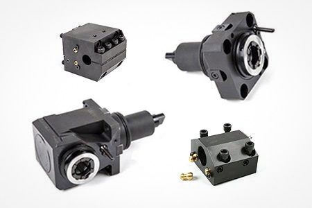
      Torrette ed utensili motorizzati
      • Torrette ed utensili motorizzati
    • Product Image
      Indagine tramite sonda
      • Indagine tramite sonda
    • Gestione di trucioli e refrigerante Haas
      Gestione di trucioli e refrigerante
      • Gestione di trucioli e refrigerante
    • Il controllo Haas
      Il controllo Haas
      • Il controllo Haas
    • Product Image
      Opzioni di prodotto
      • Opzioni di prodotto
    • Product Image
      Utensileria e fissaggio dei pezzi
      • Utensileria e fissaggio dei pezzi
    • Product Image
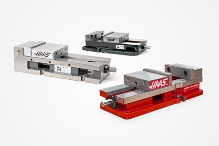
      Serraggio dei pezzi
      • Serraggio dei pezzi
    • Product Image
      Soluzioni a 5 assi
      • Soluzioni a 5 assi
      • 5 Easy Steps to 5-Axis
    • Product Image
      Automazione
      • Automazione
    • COLLEGAMENTI RAPIDI Serie speciali  Serie speciali 
      CARRIERE HAAS CARRIERE HAAS CONFIGURA E QUOTA CONFIGURA & QUOTA LISTINO PREZZI LISTINO PREZZI NOVITÀ NOVITÀ LA TUA PRIMA CNC LA TUA PRIMA CNC HAAS SIX PACK HAAS SIX PACK
      STRUMENTI DI ACQUISTO
      • Configura e quota una Haas
      • Prezzo di listino
      • Inventario disponibile
      • Finanziamento CNCA
      VUOI PARLARE CON QUALCUNO?

      Un Haas Factory Outlet (HFO) può rispondere alle tue domande e guidarti attraverso le migliori opzioni.

      CONTACT YOUR DISTRIBUTOR >
  • Why Haas
      Scopri la differenza di Haas
      Perché Haas MyHaas Comunità di formazione Industria 4.0 Certificazione Haas Testimonianze dei clienti
  • Assistenza
      Benvenuti all’Assistenza Haas
      PAGINA INIZIALE ASSISTENZA Manuali dell'operatore Procedure d’uso Guide alla risoluzione dei problemi Manutenzione preventiva Pezzi di ricambio Haas Macchine utensili Haas Video
  • Video
  • MyHaas - Un solo posto per tutto

    • Compare Quotes
      • Compare Quotes

    • Informazioni su MyHaas
      • Informazioni su MyHaas

    • Programma di certificazione CNC Haas
      • Programma di certificazione CNC Haas

    • Haas CNC Certification Program-Redirect
      • Haas CNC Certification Program-Redirect

    • Programma di certificazione CNC Haas
      • Programma di certificazione CNC Haas

    • Haas Learning Resources
      • Haas Learning Resources

    • Haas Global Learning Resources
      • Haas Global Learning Resources

    • MyHaas App Form
      • MyHaas App Form
    • COLLEGAMENTI RAPIDI Serie speciali  Serie speciali 
      CARRIERE HAAS CARRIERE HAAS CONFIGURA E QUOTA CONFIGURA & QUOTA LISTINO PREZZI LISTINO PREZZI NOVITÀ NOVITÀ LA TUA PRIMA CNC LA TUA PRIMA CNC HAAS SIX PACK HAAS SIX PACK
      STRUMENTI DI ACQUISTO
      • Configura e quota una Haas
      • Prezzo di listino
      • Inventario disponibile
      • Finanziamento CNCA
      VUOI PARLARE CON QUALCUNO?

      Un Haas Factory Outlet (HFO) può rispondere alle tue domande e guidarti attraverso le migliori opzioni.

      CONTACT YOUR DISTRIBUTOR >
  • Macchine utensili Haas
      Haas Tooling Portautensili per fresatrici Serraggio dei pezzi fresatrice Fresare Utensileria tornio Portautensili per tornio Serraggio dei pezzi nel tornio Collari e autocentranti ER Foratura Filettatura Gestione degli utensili Accessori macchine utensili Kit pacchetti Misurazione e ispezione Equipaggiamento e accessori
      COLLEGAMENTI RAPIDI A HAAS TOOLING
      NUOVI PRODOTTI NUOVI PRODOTTI
      PIÙ POPOLARE PIÙ POPOLARE
      TERMINI APERTI TERMINI APERTI
      FINANZIAMENTO FINANZIAMENTO
      Domande frequenti Domande frequenti
      KIT CREATI PER TE KIT CREATI PER TE

    • HFO Svizzera
      • HFO Svizzera
      • Informazioni
      • Assistenza
      • Formazione
      • Finanziamento
      • Showroom
      • Eventi
      • Contattaci

    • HFO Celada
      • HFO Celada
      • Home
      • A Proposito Di
      • Assistenza
      • Formazione
      • Finanziamenti
      • Eventi
      • Chi siamo
      • Inventario Showroom
    • COLLEGAMENTI RAPIDI Serie speciali  Serie speciali 
      CARRIERE HAAS CARRIERE HAAS CONFIGURA E QUOTA CONFIGURA & QUOTA LISTINO PREZZI LISTINO PREZZI NOVITÀ NOVITÀ LA TUA PRIMA CNC LA TUA PRIMA CNC HAAS SIX PACK HAAS SIX PACK
      STRUMENTI DI ACQUISTO
      • Configura e quota una Haas
      • Prezzo di listino
      • Inventario disponibile
      • Finanziamento CNCA
      VUOI PARLARE CON QUALCUNO?

      Un Haas Factory Outlet (HFO) può rispondere alle tue domande e guidarti attraverso le migliori opzioni.

      CONTACT YOUR DISTRIBUTOR >
  • Contattaci

Carrello
MyHaas Benvenuto,
!
Haas Tooling Storico degli ordini ospite MyHaas/HaasConnect Accedi Registrati Haas Tooling Il mio account Order History Return History MyHaas/HaasConnect Esci Benvenuto, Le mie macchine Ultima attività Preventivi personali Il mio account I miei utenti Esci
Trova un rivenditore
  1. Seleziona lingua
    1. English
    2. Deutsch
    3. Español - España
    4. Español - Méjico
    5. Français
    6. Italiano
    7. Português
    8. Český
    9. Dansk
    10. Nederlands
    11. Magyar
    12. Polski
    13. Svenska
    14. Русский
    15. Türkçe
    16. 中文
    17. Suomi
    18. Norsk
    19. الإنجليزية
    20. български
    21. Hrvatski
    22. Ελληνικά
    23. Română
    24. Slovenský
    25. Slovenščina
    26. 한국어
    27. 日本語
Search
×

Risultati di ricerca

Web Pages

Immagini

    • <
    • 1
    • >

CM-1 Installation

Pagina iniziale Assistenza Procedure d’uso CM - Installazione
Recently Updated Last updated: 09/13/2019

CM - Installazione


CM - Installazione

- Vai alla sezione - 1. Introduzione 2. Rimozione dell'inibitore della ruggine 3. Collegamento aereo 4. Collegamenti elettrici 5. Rimozione delle staffe di spedizione (4 passi) 6. Livellamento macchina (2 passi) 7. Movimento rapido del mandrino (1 passo) 8. Verifica della lubrificazione 9. Funzionamento della macchina (7 passi) Back to Top

Introduzione

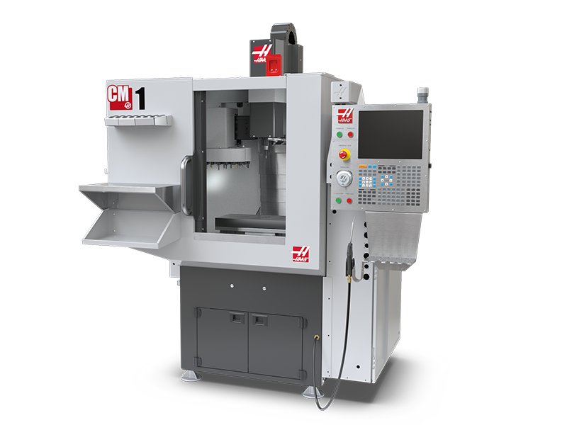
Questa procedura vi guiderà attraverso l'installazione di un VMC

Strumenti necessari:

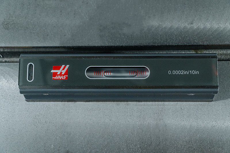
  • Livello Macchinista di precisione, 0.0005" Divisione
  • Barra di prova del mandrino di precisione, 8" lungo
  • ¾ " presa e cricchetto 
  • 1-1/2" strattone m
  • metro a nastro
  • 0.0005" o indicatore di 1 micron 
  • Per macchine da 110V: 110V Tester di recipienti elettrici con diagnosi GFCI 
  • Per macchine da 240V: 240V Tester di recipienti elettrici con diagnosi GFCI

Rimozione dell'inibitore della ruggine

For ease of removal, first use a plastic scraper to remove most of the rust inhibitor and then use WD-40 or another PH neutral degreaser to spray all the way covers and other non-painted surfaces that have been coated with rust inhibitor. Let it soak for a few minutes before removing it. Then use shop towels to remove it. For thick applications of rust inhibitor use a plastic scraper to remove it.

: https://vimeo.com/haasautomation/review/171129636/7c2a5127f9

 Important: Do not use scotch-brite or metal scrapers, these will scratch the way covers. Furthermore, to avoid any contamination of the way cover seals with the sticky residue. Do not move any of the axes until all the rust inhibitor has been removed.

Collegamento aereo

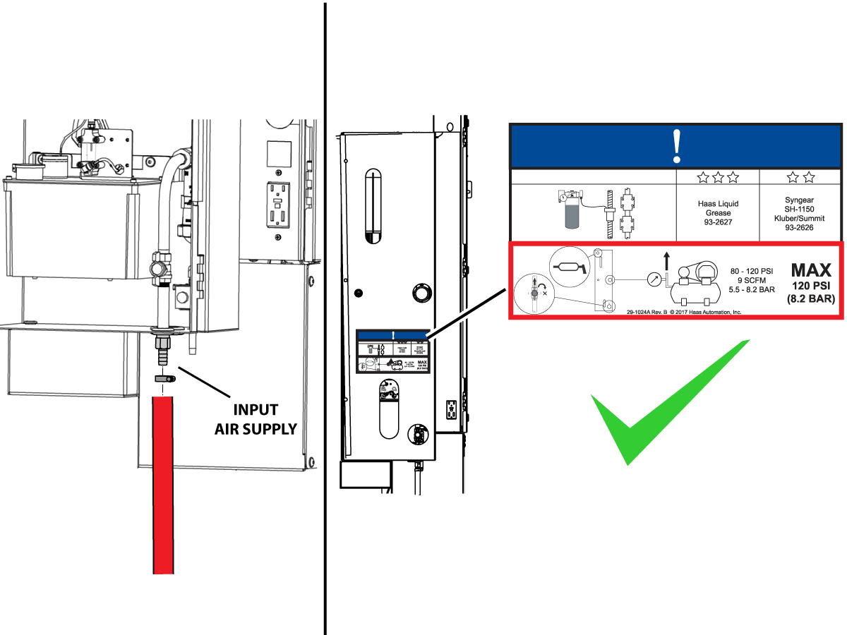
Connect the air supply at the lube panel.

 Note: For air requirements refer to the decal that is located on the lube cabinet door.

Collegamenti elettrici

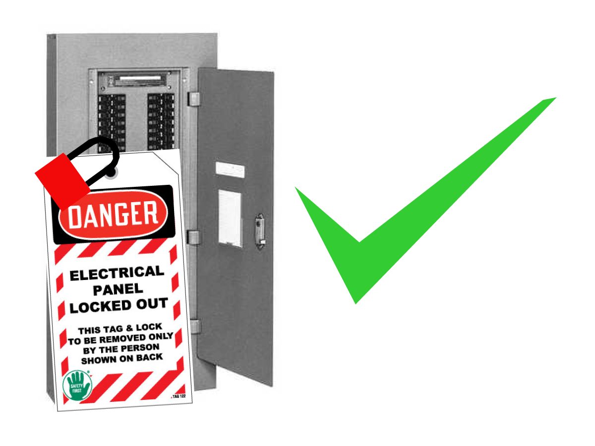
Danger: WORKING WITH ELECTRICAL SERVICES REQUIRED FOR A CNC ARE EXTREMELY HAZARDOUS. ALL POWER TO CNC MUST BE TURNED OFF LOCKOUT-TAGOUT AT THE SOURCE PRIOR TO CONNECTING THE LINE WIRES TO CNC. HOWEVER, IF THIS NOT THE CASE OR ARE NOT SURE HOW TO DO THIS, CHECK WITH APPROPIATE PERSONNEL OR OBTAIN THE NECESSARY HELP BEFORE CONTINUING. ALWAYS CHECK THE INCOMING LINES WITH AN AC VOLTAGE DETECTOR TO MAKE SURE POWER HAS BEEN DISCONNECTED.

1

Initial Control Inspection

Danger: At this point, there should be no electrical connection to the machine. Electrical panel must be closed and secured. When main switch is on, there is HIGH VOLTAGE throughout the electrical panel (including the circuit boards and logic circuits) and some components operate at high temperatures. Therefore, exercise extreme caution when working in the panel.

  • Set the main breaker switch at the upper right of the electrical panel on the back of the machine to OFF.
  • Using a screwdriver, unlock the two latches on the panel door, unlock the cabinet with the key and open the door.
  • Take sufficient time to check all the components and connectors associated with the circuit boards. Look for any cables that have become disconnected, look for any signs damage and loose parts in the bottom of the panel box. If there are any signs that the machine was mishandled, call the factory before proceeding.

2

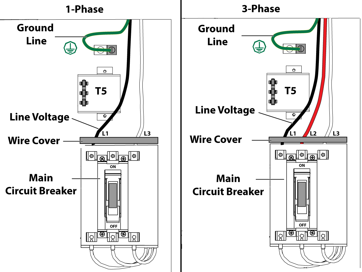
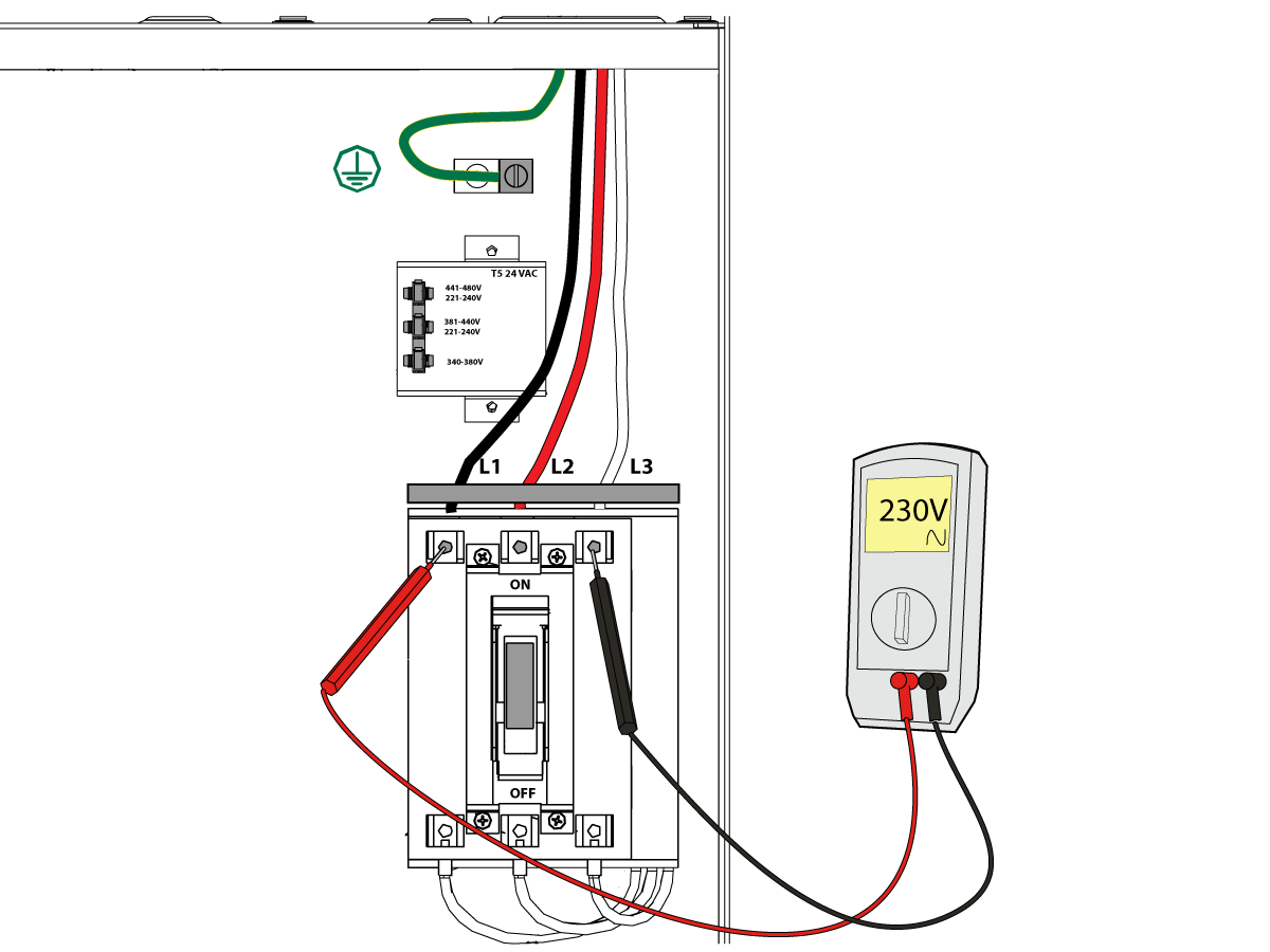
1-Phase Machines: Insert each power lead into the wire cover.  Connect the two power leads to L1 and L3 terminals on top of the main circuit breaker.

3-Phase Machines: Insert each power lead into the wire cover.  Connect the three power leads to L1, L2 and L3 terminals on top of the main circuit breaker.

Connect the separate ground line to the ground bus to the left of the terminals.

 Note: Make sure that the leads actually go into the terminal-block clamps . (A poor connection will cause the machine to run intermittently or have other problems, such as servo overloads.) To check, simply pull on the wires after the screws are tightened.

3

After the line voltage is connected to the machine, make sure that main circuit breaker (at top-right of rear cabinet) is OFF . Remove the Lockout / Tagout and Turn ON the power at the source. Using a digital voltmeter and appropriate safety procedures: 

1-Phase Machines: Measure the AC voltage across L1 & L3 at the main circuit breaker.  The AC voltage must be between 220 - 250 volts .
Note: Lower or higher than this voltage can generate low/high voltage alarms.

3-Phase Machines: Measure the AC voltage between all three pair phases at the main circuit breaker.  The AC voltage must be between 195 and 260 volts (360 and 480 volts for high voltage option).

 Note: Wide voltage fluctuations are common in many industrial areas; minimum and maximum voltage supplied to a machine while it is in operation must be known. U.S. National Electrical Code specifies that machines should operate with a variation of +5% to -5% around an average supply voltage. If problems with line voltage occur, or low line voltage is suspected, an external transformer may be used. If you suspect voltage problems, voltage should be checked every hour or two during a typical day to be sure it does not fluctuate more than +5% or -5% from an average.

4

Important: With the main circuit breaker turned OFF.

Check the transformer taps at the bottom-right corner of the rear cabinet.

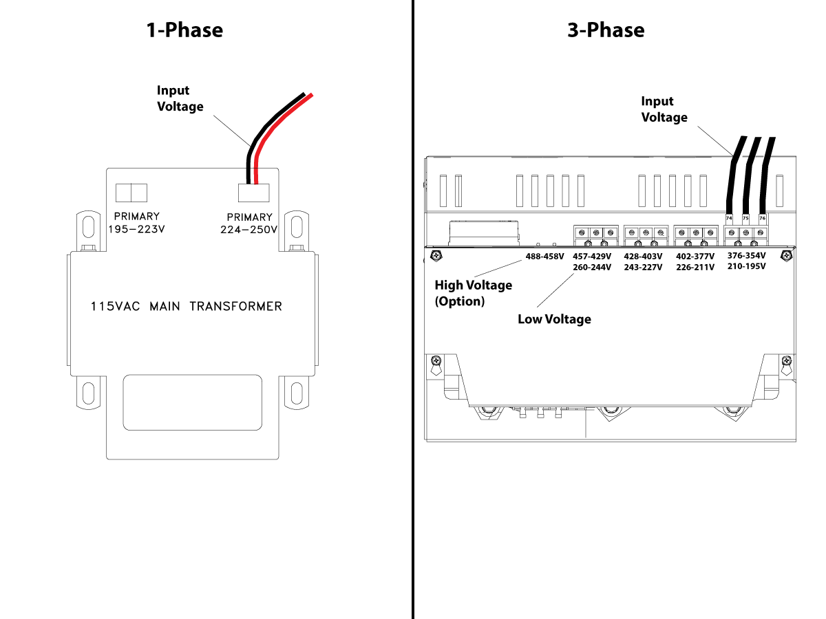
1-Phase Machines: The input voltage cable must be moved to the connector which corresponds to the average voltage measured in the above step.

3-Phase Machines:  The input voltage cables labeled 74, 75, and 76 must be moved to the terminal block triple which corresponds to the average voltage measured in the above step.

5

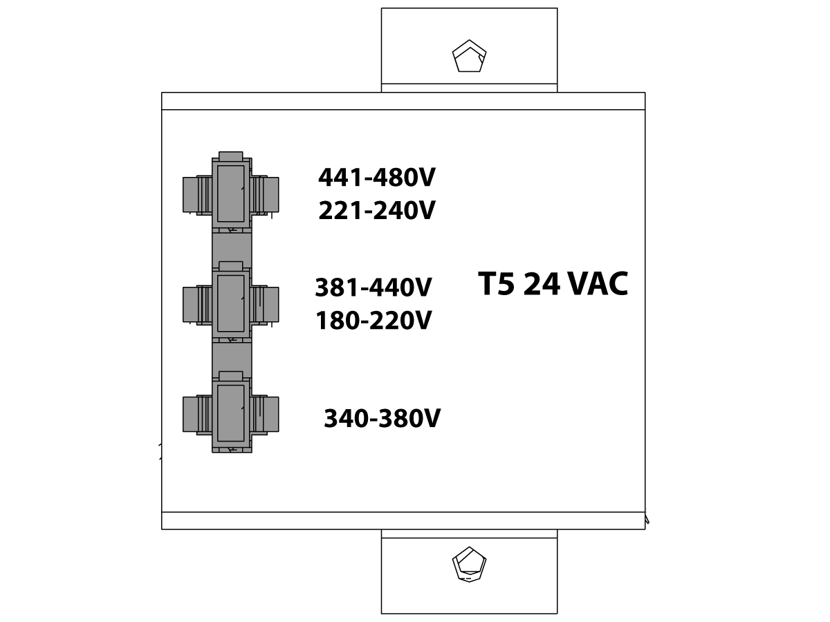
Transformer T5 supplies 24VAC used to power the main contactor. There are two versions of this transformer for use on a 240 and 400V machines. The 240V transformer has two input connectors located about two inches from the transformer, which allow it to be connected to either 180-220V or 221-240V. Users that have 220V-240V RMS input power should use the connector labeled 221-240V, while users with 190-220V input power should use the connector labeled 180-220V. Failure to use the correct input connector will result in either overheating of the main contactor or failure to reliably engage the main contactor.

The 480V (option) T5 transformer has three input connectors, labeled 340-380V, 381-440V and 441-480V. Users with 340-380V 50Hz power should use the 340-380V connector while users with 380V-440V 50Hz power should use the 381-440V connector.

Important: Set the main circuit breaker to ON. Check for evidence of problems, such as the smell of overheating components or smoke. If such problems are indicated, immediately set the main circuit breaker to OFF and call the factory before proceeding.

After the power is on, measure the voltage across the bottom terminals on the main circuit breaker. It should be the same as the measurements where the input power connects to the main breaker. If there are any problems, check the wiring.

6

Apply power to the control by pressing the Power-On switch on the front panel.

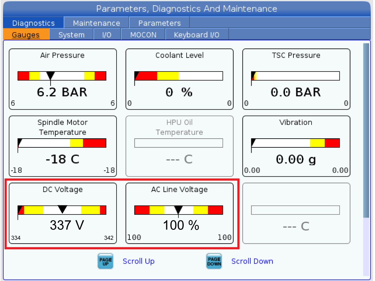
Check the DC Voltage and AC Line Voltage gauges in Diagnostics. The DC Voltage gauge must read between 310 - 360V. The AC Line Voltage must be between 90 and 105 percent. If the voltage is outside these limits, turn off the power and recheck steps 2 and 3. If the voltage is still outside these limits, call the factory.

7

Electrical power must be phased properly to avoid damage to your equipment. The Power Supply Assembly PC board incorporates a "Phase Detect" circuit with neon indicators. When the orange neon is lit (NE5), the phasing is incorrect. If the green neon is lit (NE6), the phasing is correct. If both neon indicators are lit, you have a loose wire; check the connections. Adjust phasing by setting the source power to off and then swapping L1 and L2 of the incoming power lines at the main circuit breaker.

Danger: ALL POWER TO CNC MUST BE TURNED OFF LOCKOUT-TAGOUT AT THE SOURCE PRIOR TO ADJUSTING PHASING. ALWAYS DOUBLE CHECK THE INCOMING LINES WITH AN AC VOLTAGE DETECTOR.

Turn off the power and set the main circuit breaker to OFF. Close the door, lock the latches, and turn the power back on.

Remove the key from the control cabinet and give it to the shop manager.

8

Activation

When the machine is properly placed and connected to both air and electrical power, it is ready for final installation (removing shipping blocks, leveling, spindle sweep, etc.) and software activation. The HFO service technician does this. Contact the local HFO to schedule the work.

Rimozione delle staffe di spedizione

1

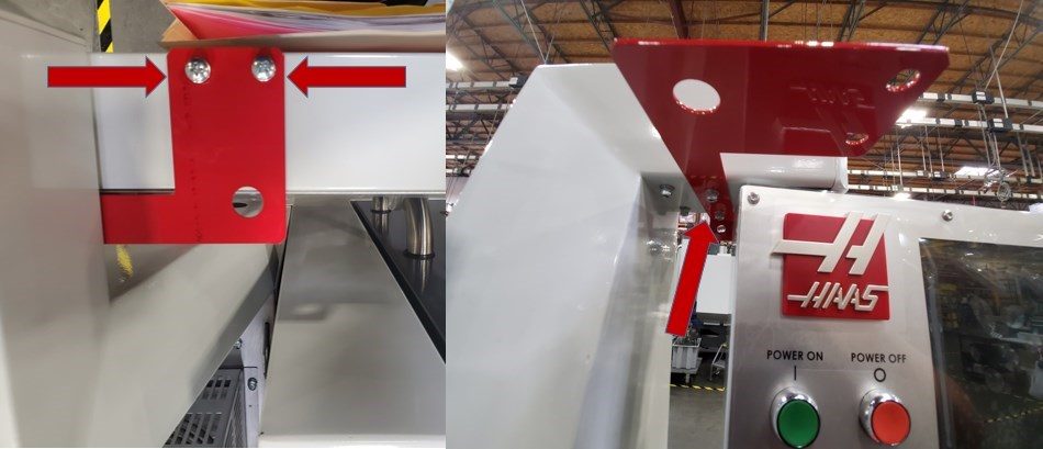
Parentesi pendente

  • Rimuovere le prime due viti tenendo il pendente nella posizione bloccata
  • Girare il pendente fuori per ottenere l'accesso alle due viti situate vicino al montante e rimuoverli. 

2

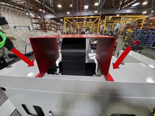
Staffa guida cavo

  • Rimuovere le due viti tenendo la staffa del cavo in posizione

3

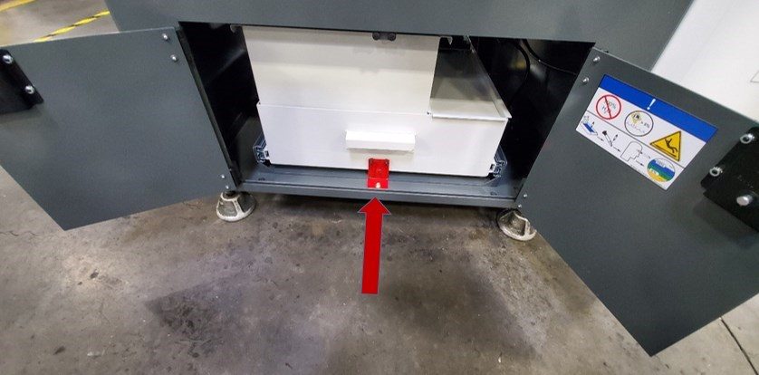
Staffa del serbatoio di raffreddamento

  • Aprire le doppie porte situate vicino alla parte inferiore della macchina e rimuovere la staffa del serbatoio del refrigerante

4

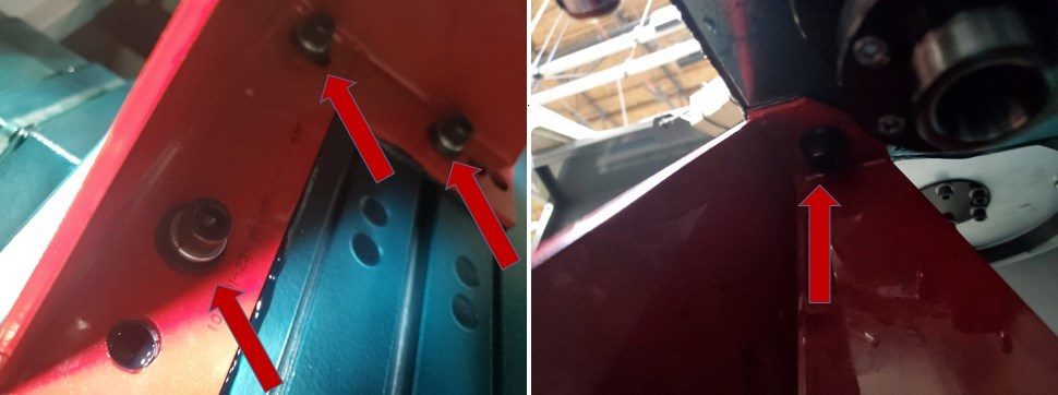
Staffa di mandrino

  • Rimuovere il bullone che collega l'alloggiamento del mandrino alla staffa del mandrino
  • Rimuovere i tre bulloni che tengono la staffa al tavolo.
Nota: A questo punto la staffa di spindle non sarà rimovibile. Rimuovere la staffa dopo aver alimentato la macchina e facendo jogging del mandrino verso l'alto

Livellamento macchina

1

  • Pulire e fare jogging il tavolo in modo che sia centrato nella macchina.
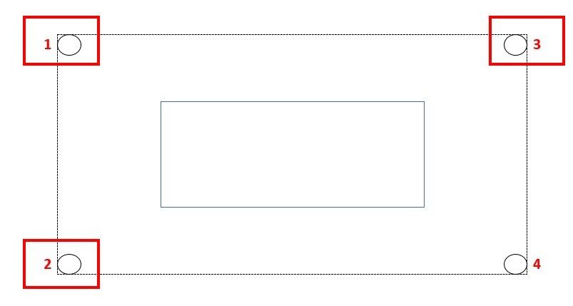
  • Posizionare il livello di precisione in modo che la lunga fiala sia parallela all'asse X. Utilizzare i slot A come riferimento 
  • Le fiale lunghe e corte saranno utilizzate per misurare i livelli dell'asse rispettivamente per x e Y
  • Vite di livellamento loosen 4 giri
  • Effettuare piccole regolazioni alle viti di livellamento 1 e 3 per regolare il livello dell'asse X. Dopo ogni nota di regolazione la posizione del  bolla nella fiala corta. 
  • Se la posizione della bolla nella fiala corta non è centrata, effettuare regolazioni alle viti di livellamento 1 e 2 come richiesto 
  • Ripetere questo processo fino a quando entrambe le bolle sono nelle loro posizioni centrali  

2

  • Regolare la vite di livellamento 4 in modo che la sua aderente contro il terreno
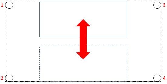
  • Eseguire il jog della tabella per posizionarla vicino alla colonna del mandrino 
  • Si noti la posizione della bolla nella lunga fiala. se la bolla non è centrata fare una piccola regolazione l'angolo inferiore
  • Ripetere questo processo con la tabella sul lato operatore della macchina

Movimento rapido del mandrino

1

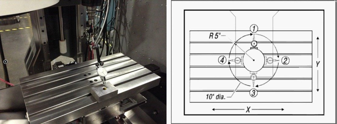
  • Fissare l'indicatore alla testa della colonna vertebrale 
  • Posizionare il tavolo e l'indicatore in modo che quando il mandrino viene spazzato misura un cerchio 10" in diametro
  • Prendere un blocco 1-2-3 e posizionarlo sul tavolo jog il mandrino verso il basso e zero l'indicatore alla posizione 1
  • Utilizzando un blocco 1-2-3 prendere misure ogni 90 gradi. la differenza in queste misurazioni non deve differire di più di 0.0005" 
  • se le misurazioni differiscono di oltre 0,0005" controllare il livello della macchina.

Verifica della lubrificazione

Funzionamento della macchina

1

Funzionamento del mandrino di prova

  • Eseguire Spindle Run nel programma 009221 che si trova nella cartella 009000.
  •  Nel caso di rumore insolito del mandrino eseguire un test di vibrazione 

Per una guida su come eseguire un test di vibrazione del mandrino si prega di vedere: 

Analisi delle vibrazioni - Interfaccia Ethernet
Analisi delle vibrazioni - Interfaccia RS-232

2

Testare il funzionamento del refrigerante 

  • Collegare la pompa del refrigerante 
  • Testare il funzionamento del refrigerante per inondazioni premendo il pulsante [Coolant] sul 

3

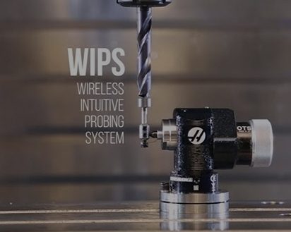
Calibrazione WIPS NGC 

  • Se la macchina include l'opzione WIPS eseguire la procedura di calibrazione (vedere link)

Per una guida su come eseguire la procedura di calibrazione WIPS, vedere:

Calibrazione WIPS NGC

4

Funzionamento della telecamera Wifi 

Se la macchina è stata fornita con l'opzione Fotocamera Wifi, vedere il seguente collegamento per le istruzioni di installazione:

Opzione fotocamera Wi-Fi - Installazione

5

Funzionamento HRT100

Se la macchina è stata fornita con una tabella rotativa HRT 100, vedere il seguente collegamento per le istruzioni di installazione:

Please add link or link text.

6

TRT70 Operazione 

Se la macchina è stata fornita con un tavolo rotante TRT 70, vedere il seguente collegamento per le istruzioni di installazione:

Installazione - TR - TRT - T5C

7

Testare gli interblocchi delle porte

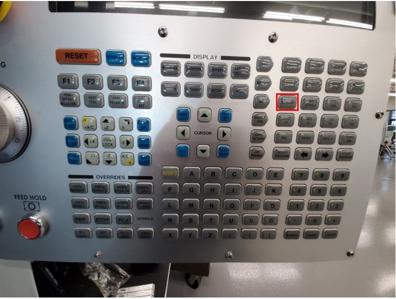
    Premere . Digitare S500 M3; passeggiata [ENTER]. Assicurarsi che la macchina NON sia in SETUP MODE controllando il KEY SWITCH sul lato del ciondolo
    • Con la porta aperta, premere [INIZIO CICLO]. La macchina dovrebbe dire di chiudere la porta e premere CYCLE START
    • Con la porta chiusa, premere [INIZIO CICLO]. Il PIN INTERLOCK dovrebbe estendersi e il mandrino inizia a ruotare
      • Mentre le serrature sono in cerca di aprire le porte
      • Il mandrino non deve se il mandrino si arresta, contattare Haas per 
TROVA UN DISTRIBUTORE
Feedback
Haas Logo

美元价格不包括关税、报关费用、保险费、增值税及运费。
USD prices DO NOT include customs duty, customs fees, insurance, VAT, or freight.

人民币价格包含关税、报关费用、货运保险和增值税, 但不包括运费。
CNY prices include customs duty, customs fees, insurance, and VAT. DOES NOT include freight.

Costi di spedizione Haas

Questo prezzo include le spese di spedizione, i dazi all'esportazione e all'importazione, l'assicurazione e qualsiasi altra spesa sostenuta durante la spedizione verso una località in Francia concordata con l'acquirente. Non è possibile aggiungere altri costi obbligatori alla spedizione di un prodotto CNC Haas.

MANTIENITI AGGIORNATO CON GLI ULTIMI SUGGERIMENTI E LA NUOVA TECNOLOGIA DI HAAS

Iscriviti subito!   

HAAS TOOLING ACCEPTS THE FOLLOWING:
  • Servizio e assistenza
  • Proprietari
  • Richiedi assistenza
  • Manuali dell’operatore
  • Pezzi di ricambio Haas
  • Richiesta di riparazione tavola rotante
  • Guide di preparazione all’installazione
  • Strumenti di acquisto
  • Configura e quota una nuova Haas
  • Inventario disponibile
  • Listino prezzi Haas
  • Finanziamento CNCA
  • Informazioni su Haas
  • Carriere
  • Certificazioni e sicurezza
  • Contatti
  • Storia
  • Termini e condizioni
  • Termini e condizioni delle macchine utensili Haas
  • Privacy
  • Garanzia
  • Community di Haas
  • Programma di certificazione Haas
  • Haas Motorsports
  • Fondazione Gene Haas
  • Comunità di formazione tecnica Haas
  • Eventi
  • Unisciti alla conversazione
  • Facebook
  • Twitter
  • Flickr
  • YouTube
  • LinkedIn
  • Instagram
  • TikTok
© 2022 Haas Automation, Inc - Macchine utensili CNC

2800 Sturgis Rd., Oxnard, CA 93030 / Toll Free: 800-331-6746
Phone: 805-278-1800 / Fax: 805-278-2255

Informativa sui cookie

Utilizziamo i cookie per migliorare l’esperienza dell’utente. La nostra Informativa sui cookie descrive quali cookie utilizziamo, perché li utilizziamo e come è possibile trovare maggiori informazioni su di essi. Conferma il tuo consenso all’utilizzo dei cookie analitici di parte nostra. Se non fornisci il tuo consenso, puoi comunque utilizzare il nostro sito web con un’esperienza utente ridotta.

Gestisci impostazioni

Informativa sui cookie

Utilizziamo i cookie per migliorare l’esperienza dell’utente. La nostra Informativa sui cookie descrive quali cookie utilizziamo, perché li utilizziamo e come è possibile trovare maggiori informazioni su di essi. Conferma il tuo consenso all’utilizzo dei cookie analitici di parte nostra. Se non fornisci il tuo consenso, puoi comunque utilizzare il nostro sito web con un’esperienza utente ridotta.

Functional Cookies

Analytics Cookies