×

Search Results

Web Pages

Images

    • <
    • 1
    • >
  • machines
    • Haas Vertical Mills
      Vertical Mills
      • Vertical Mills
      • VF Series
      • Universal Machines
      • VR Series
      • Pallet-Changing VMCs
      • Mini Mills
      • Mold Machines
      • Drill/ Tap/ Mill Series
      • Toolroom Mills
      • Compact Mills
      • Gantry Series
      • Vertical Mill/Turn
      • Extra-Large VMC
      • Double-Column Mills
      • Desktop Mill
      • Mill Auto Parts Loader
    • Product Image
      Multi-Axis Solutions
      • Multi-Axis Solutions
      • Y-Axis Lathes
      • 5-Axis Mills
    • Haas Lathes
      Lathes
      • Lathes
      • ST Series
      • Dual-Spindle
      • Toolroom Lathes
      • Chucker Lathe
      • Haas Bar Feeder V2
      • Lathe Auto Parts Loader
    • Haas Horizontal Mills
      Horizontal Mills
      • Horizontal Mills
      • 50-Taper
      • 40-Taper
    • Haas Rotaries & Indexers
      Rotaries & Indexers
      • Rotaries & Indexers
      • Rotary Tables
      • Indexers
      • 5-Axis Rotaries
      • Extra-Large Rotaries
    • Product Image
      Automation Systems
      • Automation Systems
      • Robot Systems
      • Automatic Parts Loaders
      • Pallet-Pool Systems
      • Haas Bar Feeder
      • Models
    • QUICK LINKS Special Series  Special Series 
      HAAS CAREERS HAAS CAREERS BUILD & PRICE BUILD & PRICE PRICE LIST PRICE LIST WHAT’S NEW WHAT’S NEW YOUR FIRST CNC YOUR FIRST CNC HAAS SIX PACK HAAS SIX PACK
      SHOPPING TOOLS
      • Build & Price a Haas
      • Price List
      • Available Inventory
      • CNCA Financing
      WANT TO TALK TO SOMEONE?

      A Haas Factory Outlet (HFO) can answer your questions, and walk you through your best options.

      CONTACT YOUR DISTRIBUTOR >
  • Options
    • Product Image
      Spindles
      • Spindles
    • Product Image
      Tool Changers
      • Tool Changers
    • Product Image
      4th- | 5th-Axis
      • 4th- | 5th-Axis
    • Product Image
      Turrets & Live Tooling
      • Turrets & Live Tooling
    • Product Image
      Probing
      • Probing
    • Haas Chip & Coolant Management
      Chip & Coolant Management
      • Chip & Coolant Management
    • The Haas Control
      The Haas Control
      • The Haas Control
    • Product Image
      Product Options
      • Product Options
    • Product Image
      Tooling & Fixturing
      • Tooling & Fixturing
    • Product Image
      Workholding
      • Workholding
    • Product Image
      5-Axis Solutions
      • 5-Axis Solutions
      • 5 Easy Steps to 5-Axis
    • Product Image
      Automation
      • Automation
    • QUICK LINKS Special Series  Special Series 
      HAAS CAREERS HAAS CAREERS BUILD & PRICE BUILD & PRICE PRICE LIST PRICE LIST WHAT’S NEW WHAT’S NEW YOUR FIRST CNC YOUR FIRST CNC HAAS SIX PACK HAAS SIX PACK
      SHOPPING TOOLS
      • Build & Price a Haas
      • Price List
      • Available Inventory
      • CNCA Financing
      WANT TO TALK TO SOMEONE?

      A Haas Factory Outlet (HFO) can answer your questions, and walk you through your best options.

      CONTACT YOUR DISTRIBUTOR >
  • Why Haas
      Discover the Haas Difference
      Why Haas MyHaas Education Community Industry 4.0 Haas Certification Customer Testimonials
  • Service
      Welcome to Haas Service
      SERVICE HOME Operator’s Manuals How-To Procedures Troubleshooting Guides Preventive Maintenance Haas Parts Haas Tooling Videos
  • Videos
  • Haas Tooling
      Haas Tooling Mill Toolholding Mill Workholding Milling Lathe Tooling Lathe Toolholding Lathe Workholding ER Collets & Chucks Holemaking Threading Tool Management Tooling Accessories Package Kits Measuring & Inspection Apparel & Accessories
      HAAS TOOLING QUICK LINKS
      NEW PRODUCTS NEW PRODUCTS
      MOST POPULAR MOST POPULAR
      OPEN TERMS OPEN TERMS
      FINANCING FINANCING
      FAQs FAQs
      KITS CREATED FOR YOU KITS CREATED FOR YOU
  • Haas Service Parts
      Haas Service Parts Automatic Pallet Changer Automatic Tool Changer Chip Management Coolant Counterbalance Electrical Cabinet Enclosure Field Install Options Hydraulics Lubrication Maintenance Pendant Probing Rotary Spindle Tailstock
  • Contact Us

My Cart
MyHaas Welcome,
!
Haas Tooling Guest Order History MyHaas/HaasConnect Sign In Register Haas Tooling My Account Order History Return History MyHaas/HaasConnect Sign Out Welcome, My Machines Latest Activity My Quotes My Account My Users Sign Out
Find A Dealer
  1. Select Language
    1. English
    2. Deutsch
    3. Español
    4. Français
    5. Italiano
    6. Português
    7. Český
    8. Dansk
    9. Nederlands
    10. Magyar
    11. Polski
    12. Svenska
    13. Русский
    14. Türkçe
    15. 中文
    16. Suomi
    17. Norsk
    18. الإنجليزية
    19. български
    20. Hrvatski
    21. Ελληνικά
    22. Română
    23. Slovenský
    24. Slovenščina
    25. 한국어
    26. 日本語
Search
×

Search Results

Web Pages

Images

    • <
    • 1
    • >

6 - BF - Troubleshooting

Haas Bar Feeder - Service Manual


  • 1 - BF - Introduction
  • 2 - BF - Installation
  • 3 - BF - Operation
  • 4 - BF - Push Rod and Drive Belt
  • 5 - BF - Maintenance
  • 6 - BF - Troubleshooting

Go To :

  • 6.1 Haas Bar Feeder - Troubleshooting

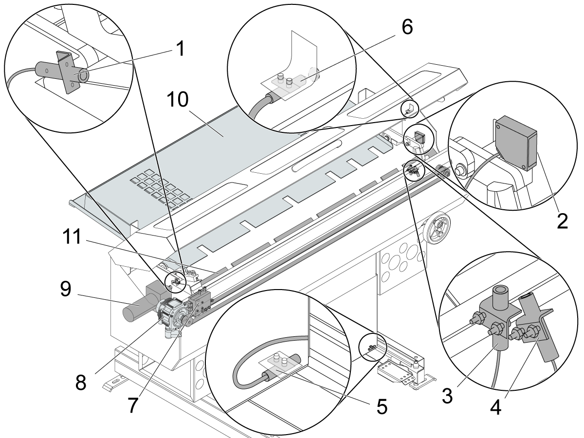
Components

Haas Bar Feeder

  1. Home switch
  2. EOB (End of Bar) switch
  3. Load "Q" switch
  4. Load bar switch
  5. In-position switch
  6. Door switch
  7. Trolley, belt, and belt tensioner assembly
  8. Servo motor (trolley)
  9. DC motor (bar loader)
  10. Charging tray
  11. Transfer tray

Symptom Table

Symptom Possible Cause Corrective Action
Alarm 702 V AXIS POSITION ERROR The trolley hit an obstruction. Adjust the charging tray.
A bar is stuck. Clear bar path.
Alarm 712 V AXIS SERVO OVERLOAD The belt skipped teeth. Grid offset/zero return and check for belt damage.
The servo motor does not operate correctly. Troubleshoot the servo motor.
Alarm 452 SERVO BAR MOTOR TIMEOUT The bar feeder lifter hit an obstruction. Remove obstructions from the lifter.
The DC motor brushes are worn. Measure resistance of the DC motor.
The proximity sensor does not operate correctly. (Load bar) Check if sensor state changes in the I/O page. If it does not. Measure voltage to the proximity sensor.
There is no voltage to the DC motor. Measure voltage to the DC motor.
Noise or electrical interference from high-power cables. Apply a ferrite bead to the sensor cables at the I/O board.
Alarm 423 SERVO BAR EOB SWITCH POSITION The proximity sensor does not operate correctly. (EOB switch) Check if sensor state changes in the I/O page. If it does not. Measure voltage to the proximity sensor.
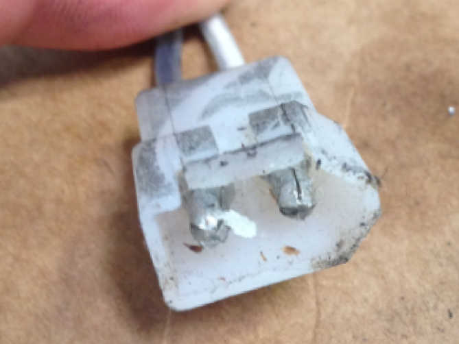
Alarm 175 GROUND FAULT DETECTED Cables are damaged or there is a contaminated electrical connection. Check for connector damage.
The brushes are contaminated or there is a carbon buildup. Check for contamination and remove dust.
Alarm 1015 (CHC) CHECK SENSOR OR BAR The proximity sensor does not operate correctly (Load "Q"). Check if sensor state changes in the I/O page. If it does not. Measure voltage to the proximity sensor.
The belt skipped teeth. Grid offset/zero return and check for belt damage.
Noise or electrical interference from high-power cables. Apply a ferrite bead to the sensor cables at the I/O board.
Alarm 9984 BAR FEEDER OUT OF POSITION The bar feeder is not latched into position. Relatch the bar feeder and check the pedal.
The proximity sensor does not operate correctly (In position switch). Check if sensor state changes in the I/O page. If it does not. Measure voltage to the proximity sensor.
Noise or electrical interference from high-power cables. Apply a ferrite bead to the sensor cables at the I/O board.
Alarm 9986 BAR LOADER MECHANISM OUT OF POSITION The proximity switches have not been activated Inspect for proper function of the proximity switches, the associated cables and the trip flag located on the end of the bar loader mecahnism
There is a mechanical blockage Inspect the bar feeder for mechanical failure or obstruction
The motor or drive clutch are not functioning properly Test the function of the motor and check to see that the drive clutch is not slipping
Noise or electrical interference from high-power cables. Apply a ferrite bead to the sensor cables at the I/O board.
Machine generates multiple Alarm 20014.1 SIO TOOL CHANGER PCB IS NOT PRESENT and 20014.0 SIO TOOL CHANGER PCB PRESENT after the I/O TC PCB is installed.

The I/O or TC PCB firmware is outdated.  Update I/O Main and TC firmware version to the latest.  Refer to Next Generation Control - I/O PCB Main Firmware - Update.
Intermittent Alarms: 452, 1015 (CHC), 9984, 9986. Noise or electrical interference from high-power cables. Apply a ferrite bead to the sensor cables at the I/O board.
Noisy The bearing on the idle pulley is damaged. Check for bearing damage.
Inconsistent push lengths Affected by previous push, pushrod timing delay, spindle liner size, chuck jaw size or grip strength. Troubleshoot the pusher.
Belt skips on motor pulley. Damaged belt or pulley. Troubleshoot the motor pulley and belt. Install Idler Pulley. See Belt Skipping - Idler Pulley Upgrade section below.
Bent Push Rod A bar is stuck. Chamfer the bar, Orient the chuck.
The bar feeder offset is incorrect. Zero return the bar feeder. Reset the bar feeder TC offset.
There is a mechanical bind in the bar loader arm. Check for worn or bent components on the pusher assembly and arm supports.
Push rod does not locate onto Cue Blade locating pins. Update to the Cue Blade Holder Block with Bull Nose Dowel Pins.
The Push Rod Arms lower or raise out of sync. Check the Push Rod Alignment. If it is correct and the issue continues. Upgrade the Bar Feeder with the Haas Bar Feeder - Torsion Bar Upgrade Kit. This kit connects both Push Rod Arms together to keep them in sync when raising and lowering the Push Rod.
Torsion bar is installed and the push rod is bending. Review the Barfeeder Misalignment Troubleshooting section for alignment corrections. 
Torsion bar is installed and the push rod arms are not sitting flush in the push rod arm stops causing misalignment 
Bar not detected Bar Feeder is not correctly aligned to machine. See the Alignment sections of Haas Bar Feeder - Installation - NGC
Bar material is reflective. Spray paint or scuff the end of the bar.
Machine generates message " NO MATERIAL FOUND" during calibration. The I/O or TC PCB firmware is outdated.  Update I/O Main and TC firmware version to the latest.  Refer to Next Generation Control - I/O PCB Main Firmware - Update.

Bar Feeder Trolley

Corrective Action:

Make sure the bar feeder charging tray is not too high. When the tray is too high, the bar feeder can attempt to load two bars. Refer to the bar feeder manual for more information.

For machines with software version 11.26 or higher, zero return all axes.

For machines with software version 11.25 or lower, set the grid offset. Refer to Axis Servo Motor - Set Grid Offset Parameter.

Bar Feeder Lifter

Corrective Action:

The DC motor (bar load) motor moves the lifter. If there is a physical obstruction blocking the movement of the lifter, the motor has a slip clutch that will allow the motor to continue to move. If there is an obstruction, the proximity sensors will not be activated. Remove any obstruction from the path of the bar feeder lifter.

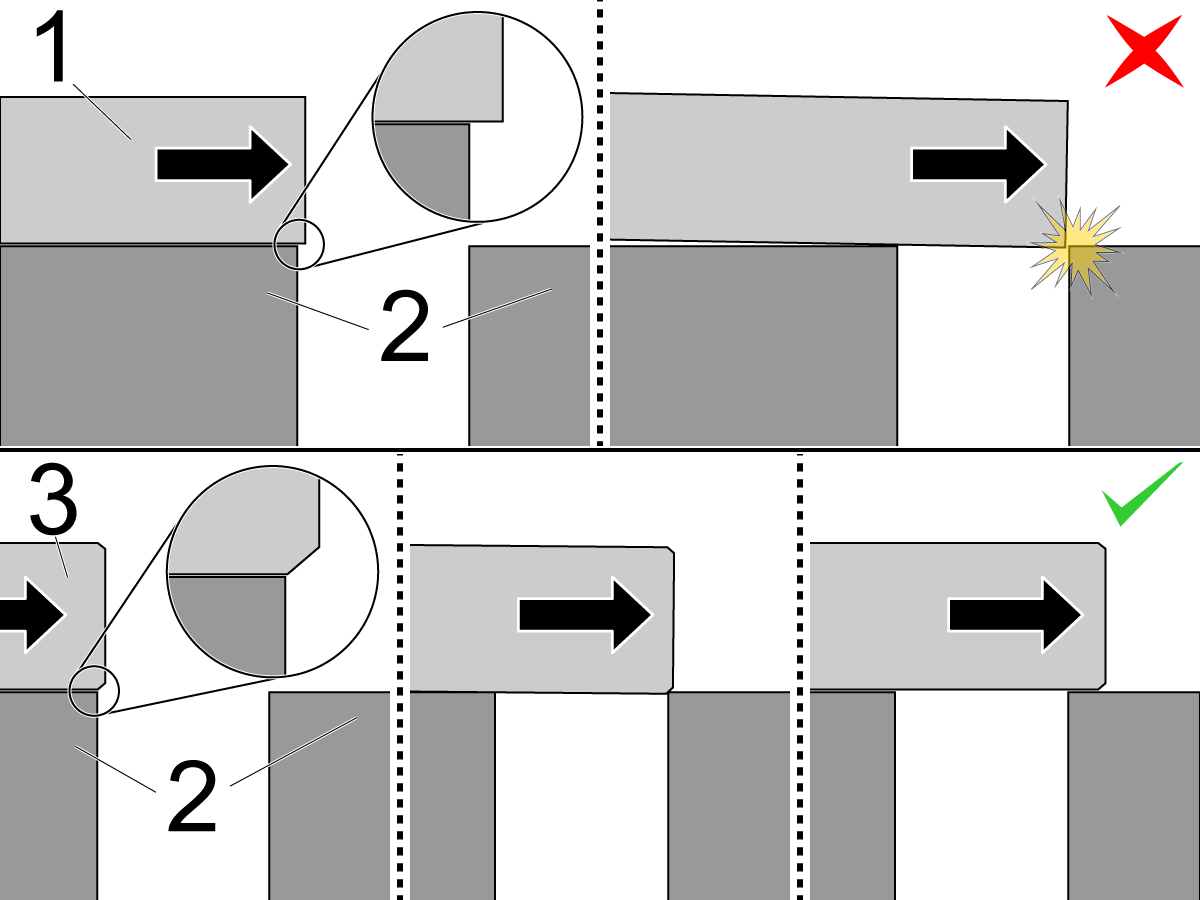
A Bar is Stuck

Corrective Action:

  1. Squared-corner bar
  2. Transfer tray
  3. Chamfered-corner bar

The bar can get stuck when:

  • The bar is not chamfered: Bars must have a smooth path. Any sharp corner in the bar path must be removed. Sharp corners can cause problems when you load a bar. Collets and chucks must have lead-in corners chamfered. Leading ends of a bar must be chamfered. When you create liners or use bar discs, use a generous lead-in chamfer.
  • The bar feeder is not aligned correctly: Refer to the bar feeder manual; it has specific instructions on how to correctly position the bar feeder and adjust the transfer tray.
  • The bar is caught on the chuck jaw: When you load a new bar, add an M19 code to your program to orient the chuck, and give the bar clearance to pass the chuck jaws.

For machines with software version 11.26 or higher, zero return all axes.

For machines with software version 11.25 or lower, set the grid offset. Refer to Axis Servo Motor - Set Grid Offset Parameter.

Clear the bar. Find and correct the root cause of the problem.

Belt Inspection

Corrective Action:

For machines with software version 11.26 or higher, zero return all axes.

For machines with software version 11.25 or lower, set the grid offset. Refer to Axis Servo Motor - Set Grid Offset Parameter.

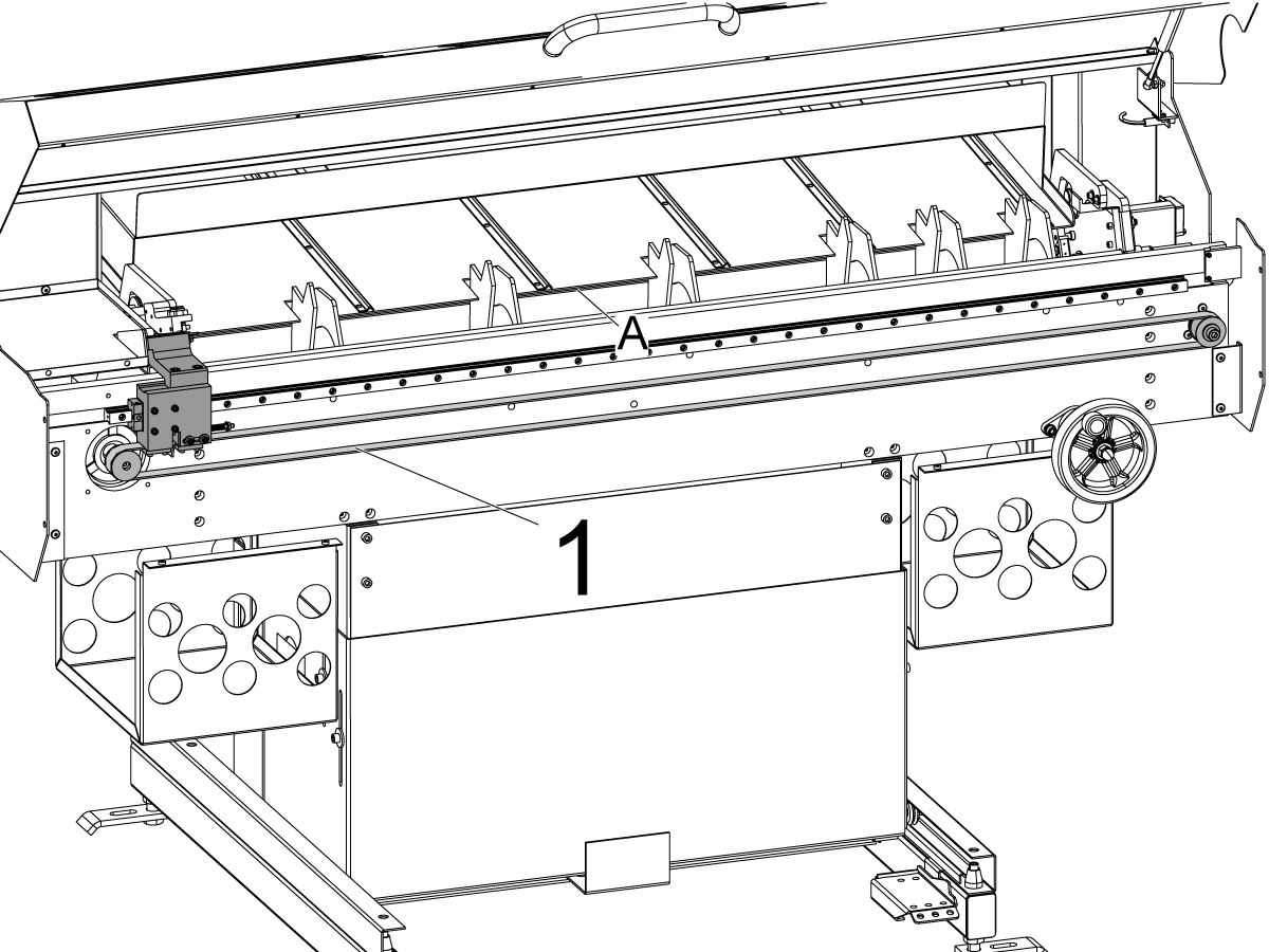
Check the belt [1] for visible signs of damage. If there is staggered V Axis motion, the belt [1] might be loose.

Belt Skipping - Idler Pulley Upgrade

If the belt is skipping, causing the pusher and bar to misposition. Perform the following troubleshooting:

Check that the belt tension is set correctly. See the Haas Bar Feeder - Drive Belt - Replacement procedure for checking and adjusting the belt tension.

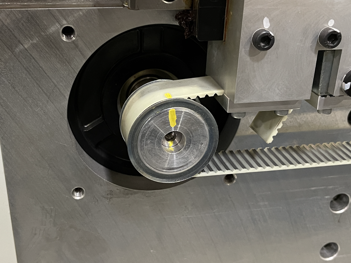
With the bar pusher at home. Draw a line on the Motor Shaft, Motor Pulley Collar (not the flange), and Belt.

Run the bar feeder pusher until the belt skips and mispositions. If the motor shaft and motor pulley are misaligned, and the motor pulley and belt are aligned. Replace the motor pulley with the Set Screw Motor Pulley.

If the motor shaft and motor pulley are aligned, and the motor pulley and belt are misaligned. Install the Idler Pulley.

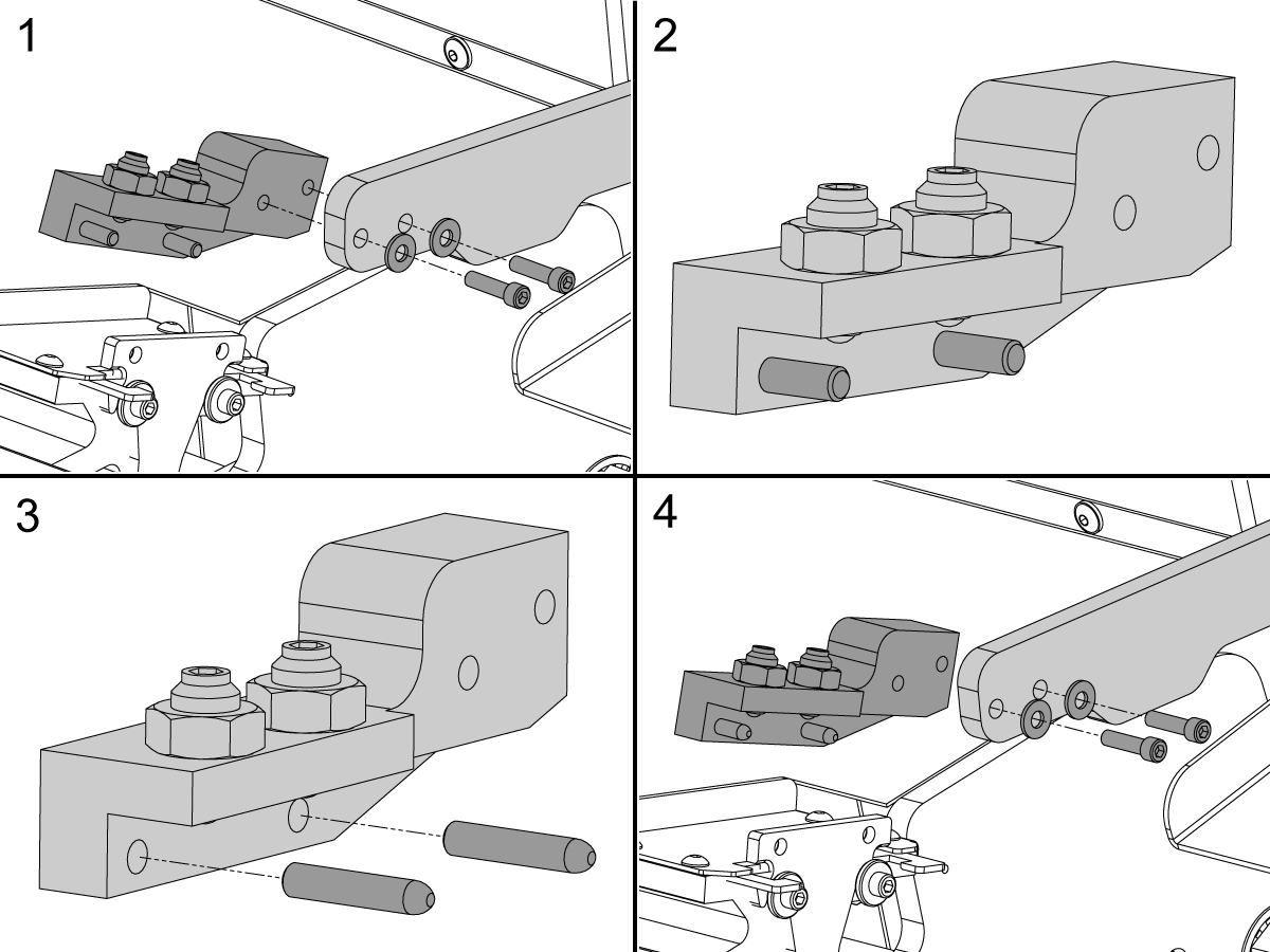
Push Rod Locating Pins Upgrade

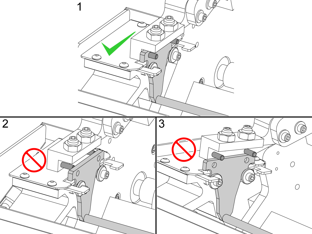
If the push rod does not locate onto the Cue Blade locating pins. The push rod will lift causing the push rod to bend.

Upgrade the Bar Feeder Cue Blade Holder Block with Bull Nose Dowel Pins.

Part Numbers:

2 x 20-9518

Remove the holder block[1]. Press the original dowel pins out of the holder block[2]. Press the bull nose dowel pins into the holder block[3]. Reinstall the holder block[4].

Haas Bar Feeder - Torsion Bar - Installation

Corrective Action:

Check the Push Rod Alignment. If it is correct and the issue continues.

Upgrade the Bar Feeder with the Haas Bar Feeder - Torsion Bar Upgrade Kit.

This kit connects both Push Rod Arms together to keep them in sync when raising and lowering the Push Rod.

 Note: If 93-3384 - BARFEEDER TORSION BAR SERVICE KIT is installed. Upgrade to the 93-3384A - BARFEEDER TORSION BAR SERVICE KIT assembly by installing the following components:

  • 20-10020 SHAFT DRIVEN PUSH ROD ARM BARFEED
  • 20-9840 PUSH ARM STOP RIGHT BARFEED

Barfeeder Misalignment Troubleshooting

1

Bar feeders built with a torsion bar or had a torsion bar installed previously may have misalignment issues. There are a troubleshooting steps to fix the issue. 

2

Complete the following alignment process before proceeding to the following steps in this section. 

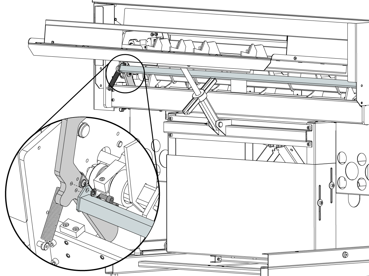
Load the 3/4 in push rod and jog the BF- axis to the cue block until the cue blade is on the dowel pins [1].

Loosen the SHCS on the push rod arm for re-alignment [2]. 

Pull the push rod towards the front of the machine and tighten the SHCS while holding the push rod in position [3]. This will adjust the cue blade to the angle of the shuttles latching plate, creating the clearance for the locating bushing. 

Unload the push rod & jog the BF-axis to the tool change offset, and manually pull down the push rod arm to confirm that the push rod is clearing the locating bushing.


3

Verify that the cue blade is perpendicular to the race of the rod of the push rod assembly. 

If the cue blade is at an angle replace the push rod assembly.

Confirm that the tool change offset is still valid and realign the cue blade holder. 

Push Rod Alignment

4

Visually inspect if the push rod arms are resting above the stops. 

5

If the push rod arms are not making contact with the bottom of the stops slide a piece of paper between the arm and the inner side of the stops while in the loaded position [1].

Be sure to check the same side on each stop (i.e left side of both stops) to check if the pushrod is shifted in one direction.  

6

If there is contact on both stops in the same direction there is play in the pivot shaft that will allow for the position to be adjusted by tapping the pivot shaft with a rubber mallet.

7

If there is contact on a single stop:

  1. Confirm that the stops are to print
    • The distance from the edge of the part to the left side of the gap [1] is 1.453 in (36.906 mm)
    • The gap [2] is .510 in (12.954 mm)
  2. Remove the stop [2] on the right side and move the arm to the loaded position. 
    • If arm fully rests on the left stop and is fully loaded, open up dimension [1] by grinding down the left side of the stop or replace the stop with the new stop in the following step. 
    • If the arm does not fully rest on the bottom of the stop or the push rod bends during loading replace the torsion bar [4]  Haas Bar Feeder - Torsion Bar - Installation  
      • Redo previous steps/checks after replacing. 

8

Order PN: 20-9840 PUSH ARM STOP RIGHT BARFEED and replace the right push arm stop. 

9

If the push rod arm is sitting flush or only slightly above the stops do the following steps:

Load the 3/4 in push rod and jog the BF- axis to the cue block until the cue blade is on the dowel pins [1].

Loosen the SHCS on the push rod arm for re-alignment[2]. 

Pull the push rod towards the front of the machine and tighten the SHCS while holding the push rod in position [3]. This will adjust the cue blade to the angle of the shuttles latching plate, creating the clearance for the lcoating bushing. 

Unload the push rod & jog the BF-axis to the tool change offset , and manually pull down the push rod arm to confirm that the push rod is clearing the locating bushing.

NOTE: If the issue continues to persist opening up the thru holes on the push rod arm [2] can be done as a last resort. The recommended drill to use is a 25/64 in. drill.

Servo Motor

Corrective Action:

Make sure the motor connections are properly seated and the cables are not damaged.

Go to Servo Amplifier - Troubleshooting Guide and Sigma 5 - Axis Servo Motor and Cables - Troubleshooting Guide. Check for shorts to the motor.

DC Motor and Clutch Inspection

DC Motor Inspection:

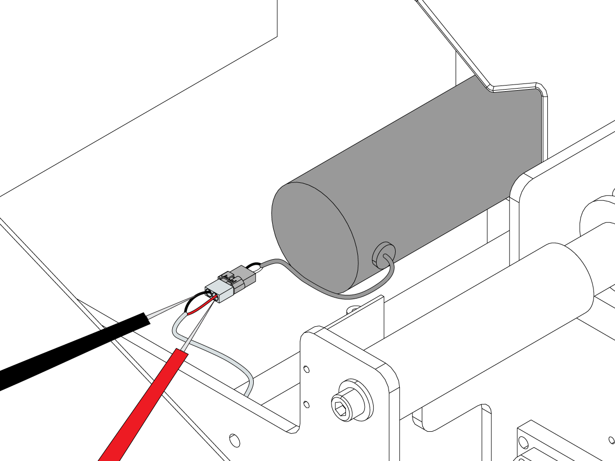
Run the DC motor: use G105 Q9 (Load Bar Stock) or G105 Q8 (Unload Bar Stock). Measure for DC voltage at the connector on the motor:

Adjust the multimeter range to 0.0 and set it for Min/Max. The power to the motor will only be on for one second before an alarm is generated and the power is shut off. The reading must be a minimum of 160 VDC, or show a signal change, when it is commanded to run. Some multimeters are not fast enough to read the voltage before the alarm occurs. It should still show a signal change or OL before the alarm is generated.

If there is no voltage and the signal does not change, go to I/O PCB - Troubleshooting Guide (Classic Haas Control).

Clutch Inspection:

If the motor is functioning correctly but there is no motion of the Bar loader, check to see if the drive clutch is slipping.  If the clutch is slipping, remove the clutch and retorque the assembly to 40 ft lbs

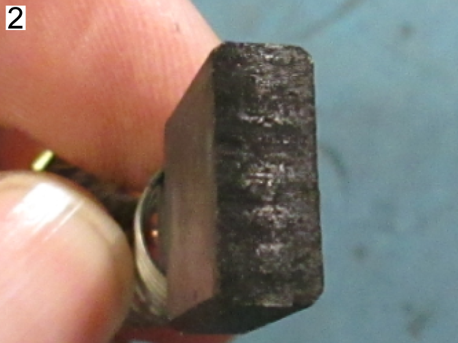
Motor Brushes

Corrective Action:

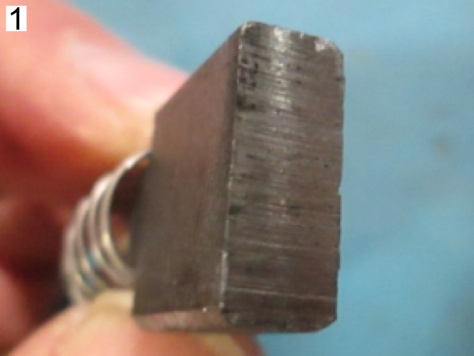
  1. Normal wear
  2. Excessive wear

Disconnect the motor from the connector. Measure the resistance from pin to pin. The resistance must be between 5-20 Ohms. Measure the resistance from one of the pins to the motor chassis.

The resistance must be greater than 100k Ohms. If the measurements are less, there is not a good contact between the brushes and the commutator. Clean any contamination between the brushes and the commutator. Brushes that have too much wear are faulty. New brushes are approximately 0.6" (15.4 mm) in length.

Proximity Sensors

Corrective Action:

Test the sensor for correct operation: hold a steel object in front of the sensor. If the sensor lights up, the sensor is not faulty. If the sensor does not light up, continue to further troubleshoot the proximity sensor.

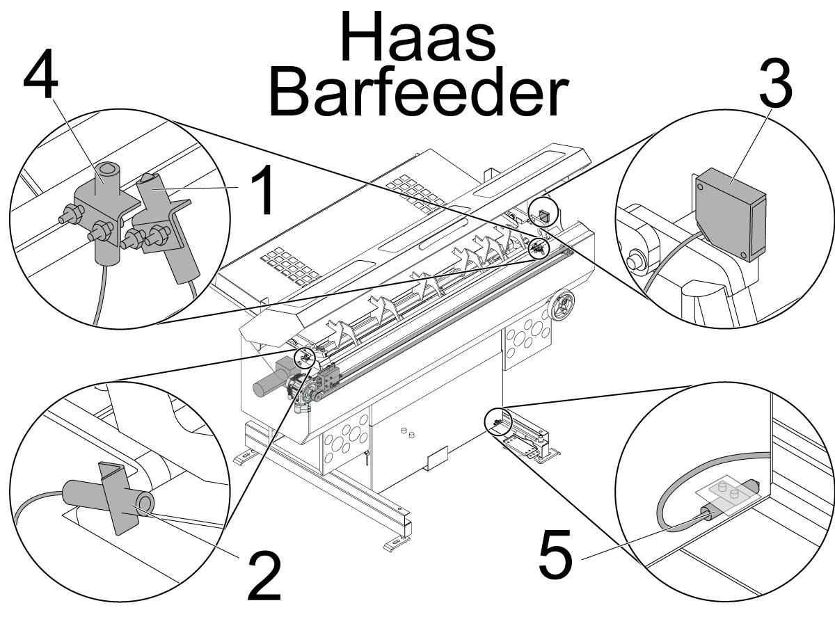
Find the correct sensor to troubleshoot:

  1. Load bar (Alarm 452) (Alarm 9986)
  2. Home switch (Alarm 469)
  3. EOB switch (Alarm 423)
  4. Load "Q" (Alarm 1015 CHC)
  5. In-position (Alarm 9984) - Before you attempt to troubleshoot the In-position switch, unlatch and re-latch the bar feeder using the foot pedals.
  6. Door switch (No alarm) - When the door switch detects the door is open, the bar feeder will operate at 25% normal speed. If this switch does not operate correctly, it will operate at 25% normal speed while the door is closed.

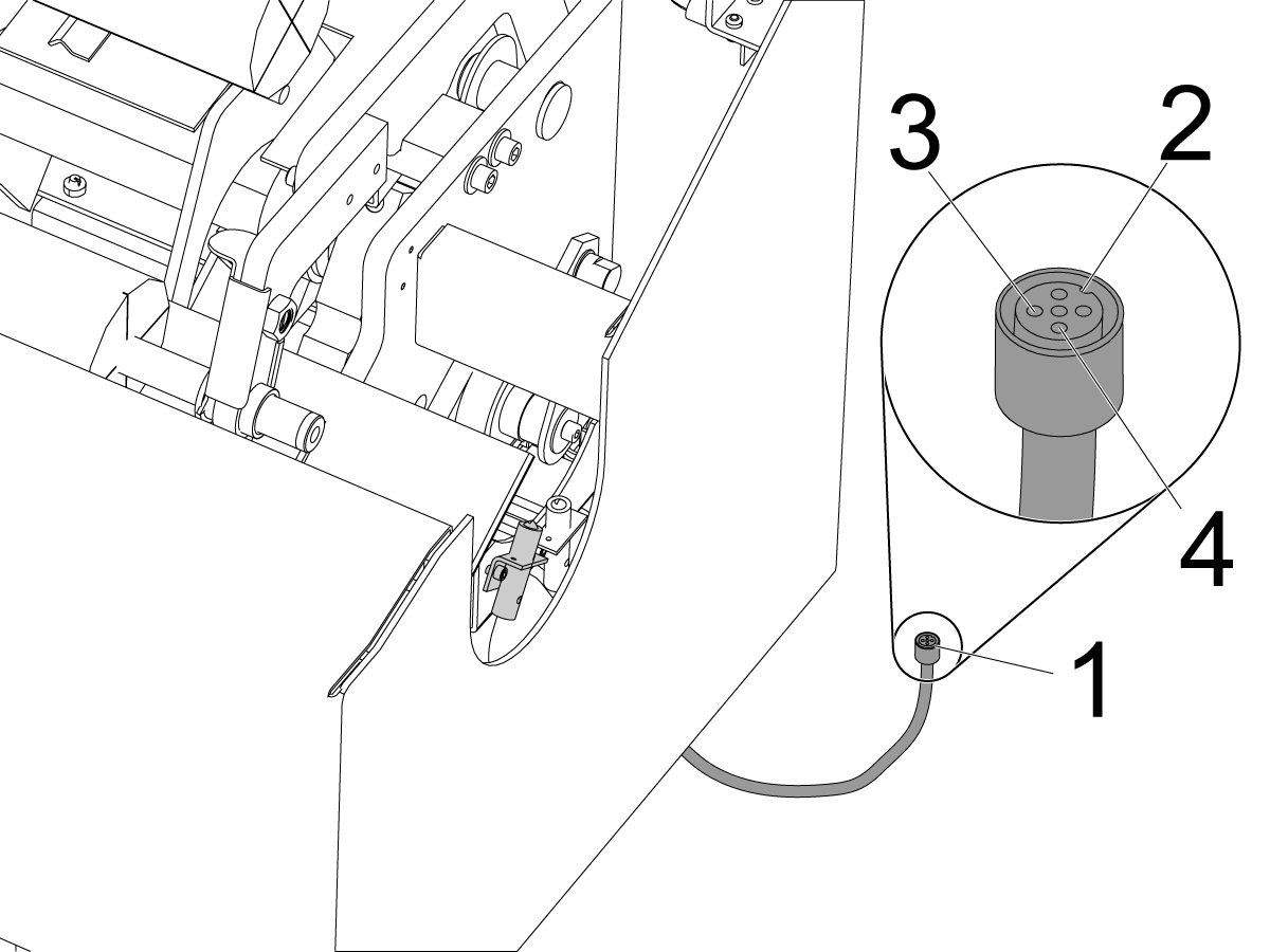
Disconnect the cable [1] from the sensor. Use the marker [2] on the cable connector to measure the correct pins. Measure the voltage between the pins [3] and [4] on the cable connector. Make sure to use a multimeter with needle tipped probes.

The correct voltage is 12 VDC.

If voltage is correct, the sensor is at fault. Go to Proximity Sensor - Troubleshooting Guide to further troubleshoot the proximity sensor.

If there is no voltage, go to I/O PCB - Troubleshooting Guide (Classic Haas Control).

Electrical Cables

Corrective Action:

Perform a visual inspection of the motor cable and connectors. Make sure that the cable is in good condition and that the connectors are clean and secure.

Barfeeder is not Latched

Corrective Action:

Relatch the bar feeder and check the release pedal.

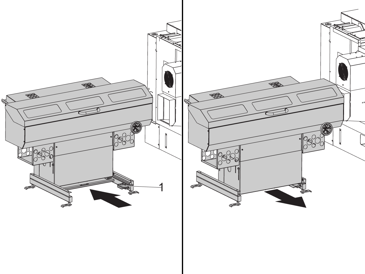
Step on the release pedal [1] and move the bar feeder to the Lockout/Lathe Setup position. Then move it back to the Feed/Auto postion.

Idler Pulley Inspection

Corrective Action:

A damaged bearing can cause excessive noise.

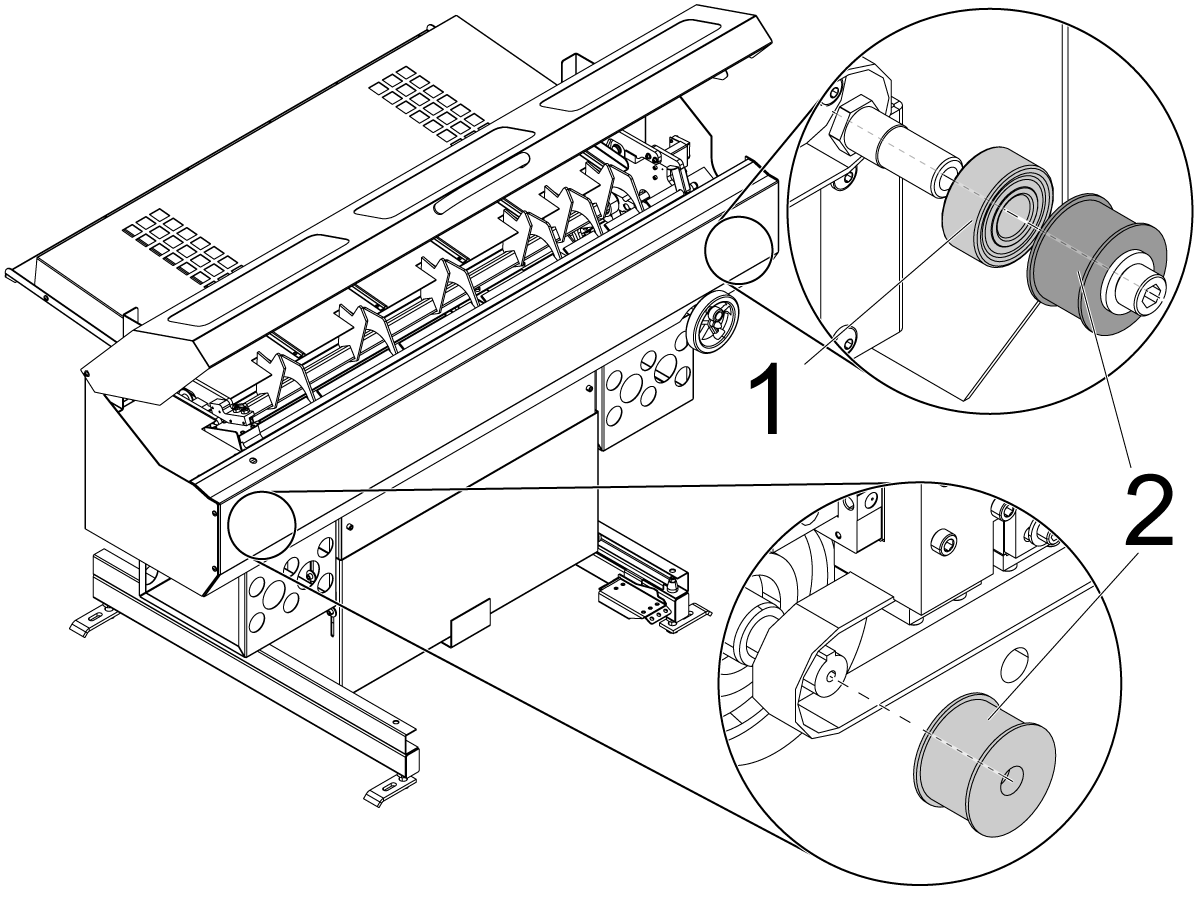
Remove the bearing [1] from the idle pulley. Check the bearing for any rough movement or loose components.

Check for wear on the pulleys [2] on both ends of the belt.

Inconsistent Push Lengths

Corrective Action:

The length of the push can be affected by the previous push: If the previous part over-shoots, the next push will be shorter. If the previous part slides back into the chuck, the next part will be long.

The pushrod moves away from the bar too soon: If the push rod moves away before the chuck can close, it can cause the bar to move back. This is more common with the collet chuck. Adjust Parameter 249 CHUCK CLAMP DELAY.

The spindle liner is too big, or there is no spindle liner: The chuck does not pull the bar against the rod when clamping or the chuck jaws are thinner. The thin jaws can cause the material to rock on the open jaws and fall forward or backwards. Material can also hit the back of the chuck and spring forward. Adjust the spindle liner to the correct size for the bar.

The bar moves after the pusher stops: Reduce the push speed: Adjust Parameters 316, 317, and 323.

Bar Loader Arm

Corrective Action:

There is mechanical binding in the bar loader arm: Check for worn or damaged latch plates [1] on the pusher assembly. The latch must open fully when the pusher retracts. Check both of the loader arms for loose hardware [2] and excessive movement. They should have aproximately 1/4" of side-to-side movement. Check for binding on the arm stop block [3].

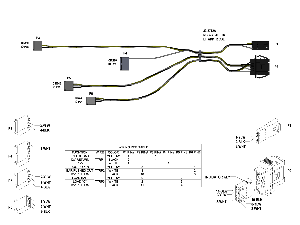
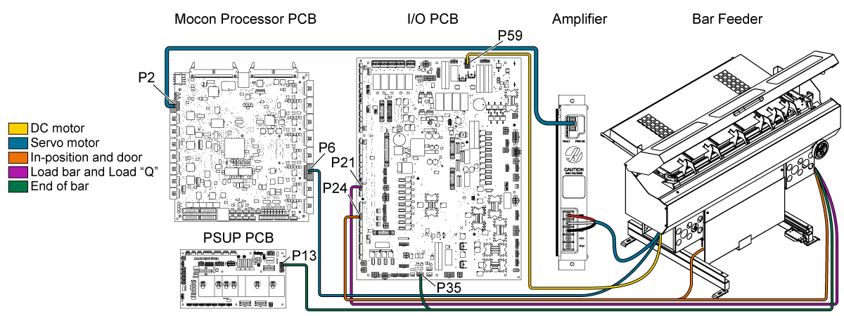
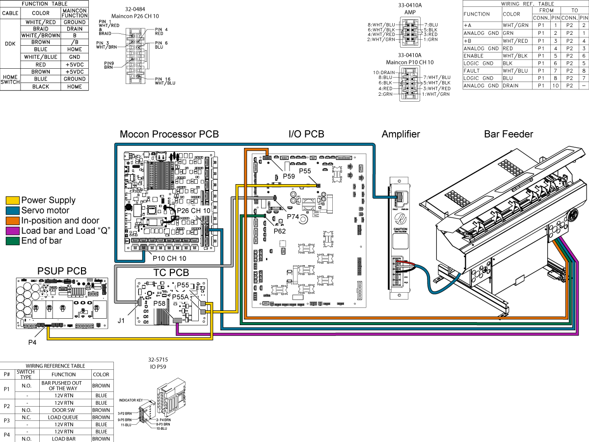
CHC Bar Feeder Electrical Diagram

FIND DISTRIBUTOR
Feedback
Haas Logo

美元价格不包括关税、报关费用、保险费、增值税及运费。
USD prices DO NOT include customs duty, customs fees, insurance, VAT, or freight.

人民币价格包含关税、报关费用、货运保险和增值税, 但不包括运费。
CNY prices include customs duty, customs fees, insurance, and VAT. DOES NOT include freight.

Haas Delivered Price

This price includes shipping cost, export and import duties, insurance, and any other expenses incurred during shipping to a location in France agreed with you as a buyer. No other mandatory costs can be added to the delivery of a Haas CNC Product.

KEEP UP WITH THE LATEST HAAS TIPS AND TECHNOLOGY...

Sign up now!   

HAAS TOOLING ACCEPTS THE FOLLOWING:

  • Service & Support
  • Owners
  • Request Service
  • Operator Manuals
  • Haas Parts
  • Rotary Repair Request
  • Pre-Install Guides
  • Shopping Tools
  • Build & Price a New Haas
  • Available Inventory
  • The Haas Price List
  • CNCA Financing
  • About Haas
  • Careers
  • Certifications & Safety
  • Contact Us
  • History
  • Terms & Conditions
  • Haas Tooling Terms & Conditions
  • Privacy
  • Warranty
  • Haas Community
  • Haas Certification Program
  • Haas Motorsports
  • Gene Haas Foundation
  • Haas Technical Education Community
  • Events
  • Join the Conversation
  • Facebook
  • Twitter
  • Flickr
  • YouTube
  • LinkedIn
  • Instagram
  • TikTok
© 2022 Haas Automation, Inc – CNC Machine Tools

2800 Sturgis Rd., Oxnard, CA 93030 / Toll Free: 800-331-6746
Phone: 805-278-1800 / Fax: 805-278-2255

Cookie Notice

We use cookies to improve your user experience. Our Cookie Notice describes which cookies we use, why we use them, and how you can find more information about them. Please confirm you consent to us using analytics cookies. If you do not consent, you may still use our website with a reduced user experience.

Manage Settings

Cookie Notice

We use cookies to improve your user experience. Our Cookie Notice describes which cookies we use, why we use them, and how you can find more information about them. Please confirm you consent to us using analytics cookies. If you do not consent, you may still use our website with a reduced user experience.

Functional Cookies

Analytics Cookies