MyHaas Welcome,
!
Haas Tooling Guest Order History MyHaas/HaasConnect Sign In Register Haas Tooling My Account Order History Return History MyHaas/HaasConnect Sign Out Welcome, My Machines Latest Activity My Quotes My Account My Users Sign Out
Find Your Distributor
  1. Select Language
    1. English
    2. Deutsch
    3. Español - España
    4. Español - México
    5. Français
    6. Italiano
    7. Português
    8. Český
    9. Dansk
    10. Nederlands
    11. Magyar
    12. Polski
    13. Svenska
    14. Türkçe
    15. 中文
    16. Suomi
    17. Norsk
    18. الإنجليزية
    19. български
    20. Hrvatski
    21. Ελληνικά
    22. Română
    23. Slovenský
    24. Slovenščina
    25. 한국어
    26. 日本語
    27. Українська
  • machines Main Menu
    • Haas Vertical Mills Vertical Mills
      Vertical Mills
      Vertical Mills View All
      • Vertical Mills
      • VF Series
      • Universal Machines
      • VR Series
      • VP-5 Prismatic
      • Pallet-Changing VMCs
      • Mini Mills
      • Mold Machines
      • High-Speed Drill Centers
      • Drill/Tap/ Mill Series
      • Toolroom Mills
      • Compact Mills
      • Gantry Series
      • SR Sheet Routers
      • Extra-Large VMC
      • Double-Column Mills
      • Control Simulator
      • Mill Automatic Parts Loader
      • VMC/UMC Side-Loading Automatic Parts Loader
      • Compact Automatic Parts Loader
    • Product Image Multi-Axis Solutions
      Multi-Axis Solutions
      Multi-Axis Solutions View All
      • Multi-Axis Solutions
      • Y-Axis Lathes
      • 5-Axis Mills
    • Haas Lathes Lathes
      Lathes
      Lathes View All
      • Lathes
      • ST Series
      • Dual-Spindle
      • Box Way Series
      • Toolroom Lathes
      • Chucker Lathe
      • Haas Bar Feeder V2
      • Lathe Automatic Parts Loader
    • Haas Horizontal Mills Horizontal Mills
      Horizontal Mills
      Horizontal Mills View All
      • Horizontal Mills
      • 50-Taper
      • 40-Taper
    • Haas Rotaries & Indexers Rotaries & Indexers
      Rotaries & Indexers
      Rotaries & Indexers View All
      • Rotaries & Indexers
      • Rotary Tables
      • Indexers
      • 5-Axis Rotaries
      • Extra-Large Rotaries
    • Special Series
      Special Series
      Special Series View All
      • Special Series
      • EU_Series_Redirect
    • Product Image Automation Systems
      Automation Systems
      Automation Systems View All
      • Automation Systems
      • Mill Automation
      • Lathe Automation
      • Automation Models
    • Haas Drill Centers Desktop Machines
      Desktop Machines
      Desktop Machines View All
      • Desktop Machines
      • Desktop Mill
      • Desktop Lathe
    • Haas Shop Equipment Shop Equipment
      Shop Equipment
      Shop Equipment View All
      • Shop Equipment
      • Bandsaw
      • Knee Mill
      • Surface Grinder, 2550
      • Surface Grinder, 3063
      • Laser Cutting Machine
    • QUICK LINKS Special Series  Special Series 
      EU SERIES EU SERIES BUILD & PRICE | PRICE LIST BUILD & PRICE | PRICE LIST In-Stock Machines In-Stock Machines WHAT’S NEW WHAT’S NEW YOUR FIRST CNC YOUR FIRST CNC
      SHOPPING TOOLS
      • Build & Price a Haas
      • Price List
      • Available Inventory
      • CNCA Financing
      WANT TO TALK TO SOMEONE?

      A Haas Factory Outlet (HFO) can answer your questions, and walk you through your best options.

      CONTACT YOUR DISTRIBUTOR >
  • Options Main Menu
    • Product Image Spindles
      Spindles
      Spindles View All
      • Spindles
    • Product Image Tool Changers
      Tool Changers
      Tool Changers View All
      • Tool Changers
    • Product Image 4th- | 5th-Axis
      4th- | 5th-Axis
      4th- | 5th-Axis View All
      • 4th- | 5th-Axis
    • Product Image Turrets & Live Tooling
      Turrets & Live Tooling
      Turrets & Live Tooling View All
      • Turrets & Live Tooling
    • Product Image Probing
      Probing
      Probing View All
      • Probing
    • Haas Chip & Coolant Management Chip & Coolant Management
      Chip & Coolant Management
      Chip & Coolant Management View All
      • Chip & Coolant Management
    • The Haas Control The Haas Control
      The Haas Control
      The Haas Control View All
      • The Haas Control
    • Product Image Product Options
      Product Options
      Product Options View All
      • Product Options
    • Product Image Tooling & Fixturing
      Tooling & Fixturing
      Tooling & Fixturing View All
      • Tooling & Fixturing
    • Product Image Workholding
      Workholding
      Workholding View All
      • Workholding
    • Product Image 5-Axis Solutions
      5-Axis Solutions
      5-Axis Solutions View All
      • 5-Axis Solutions
      • 5 Easy Steps to 5-Axis
    • QUICK LINKS Special Series  Special Series 
      EU SERIES EU SERIES BUILD & PRICE | PRICE LIST BUILD & PRICE | PRICE LIST In-Stock Machines In-Stock Machines WHAT’S NEW WHAT’S NEW YOUR FIRST CNC YOUR FIRST CNC
      SHOPPING TOOLS
      • Build & Price a Haas
      • Price List
      • Available Inventory
      • CNCA Financing
      WANT TO TALK TO SOMEONE?

      A Haas Factory Outlet (HFO) can answer your questions, and walk you through your best options.

      CONTACT YOUR DISTRIBUTOR >
  • Why Haas Main Menu
      Discover the Haas Difference
    • Why Haas
    • MyHaas
    • Education Community
    • Industry 4.0
    • Haas Certification
    • Customer Testimonials
  • Service Main Menu
      Welcome to Haas Service
      SERVICE HOME Operator’s Manuals How-To Procedures Troubleshooting Guides Preventive Maintenance Haas Parts Haas Tooling Videos
  • Videos Main Menu
  • Main Menu
    • View All
    • View All
      • Fiber Laser
    • View All
    • View All
      • HTEC Curriculum Support
    • View All
      • Haas 10 kg Cobot Package
      • Cobot Kits
    • View All
    • View All
      • 4 - AUTOMATION SYSTEMS
      • Mill Toolholding
      • Carousel-V2
    • View All
    • View All
    • View All
      • VF-4SS
    • View All
    • QUICK LINKS Special Series  Special Series 
      EU SERIES EU SERIES BUILD & PRICE | PRICE LIST BUILD & PRICE | PRICE LIST In-Stock Machines In-Stock Machines WHAT’S NEW WHAT’S NEW YOUR FIRST CNC YOUR FIRST CNC
      SHOPPING TOOLS
      • Build & Price a Haas
      • Price List
      • Available Inventory
      • CNCA Financing
      WANT TO TALK TO SOMEONE?

      A Haas Factory Outlet (HFO) can answer your questions, and walk you through your best options.

      CONTACT YOUR DISTRIBUTOR >
  • Haas Tooling Main Menu
      Automation Accessories Shop Support Mill Toolholding Mill Cutting Tools Boring Systems Mill Workholding Lathe Toolholding Lathe Cutting Tools Lathe Workholding Package Kits ER Collets & Chucks Holemaking Threading Broaching Tombstones & Kits Manual Chucks For Milling Deburring & Abrasives Tool Presetter & Heat Shrinkers Storage & Handling Machine Maintenance Tooling Accessories Apparel & Accessories Measuring & Inspection Winner's Circle Winner's Circle Clearance Today's Hot Deals
    • Haas Tooling
    • Winner's Circle
      Winner's Circle Shop All
      • WINNERS_CIRCLE-1Y
    • Winner's Circle
      Winner's Circle Shop All
      • WC-1Y-EU
    • Today’s Hot Deals
      Today’s Hot Deals Shop All
      • Mill Toolholding
      • Mill Tooling
      • Measuring & Inspection
      • Boring Systems
      • Mill Workholding
      • Shell Mill Kits
      • Lathe Toolholding
      • Lathe Tooling
      • Lathe Workholding
      • ER Collets & Chucks
      • Holemaking
      • Threading
      • Broaching
      • Tool Storage
      • Apparel & Accessories
    • Clearance
      Clearance Shop All
    • Measuring & Inspection
      Measuring & Inspection Shop All
      • Probe Kits & Accessories
      • Edge & Center Finders
      • Comparative Measuring Gauges
      • Height Gauges
      • Calipers
      • Threaded Plug & Ring Gauges
      • Gauge Blocks
      • Pin Gauges
      • Drop Indicators
      • Dial Test Indicators
      • Bore Gauges
      • Indicator Accessories
      • V Blocks
      • Setup Blocks
      • Depth Measuring
      • Micrometers
      • Micrometer Accessories
      • Micrometer Kits
      • Bore Gauge Kits
      • Starter Kits
      • Indicator Kits
      • Caliper Kits
      • Toolholder Check Station
      • Height Setters
      • Coordinate Measuring Machines
    • Automation Accessories
      Automation Accessories Shop All
      • Cobot Kits
      • Cobot Kits
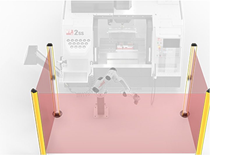
      • Protective Barriers
      • Grippers
      • Robot Cell Accessories
    • Shop Support
      Shop Support Shop All
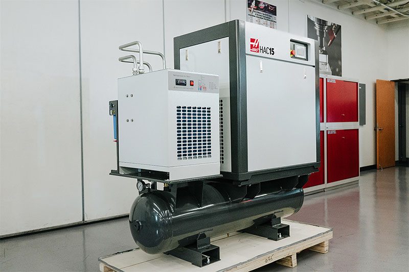
      • Air Compressors
      • Laser Marking Machines
      • Bandsaw Blades
      • Bandsaw Accessories
      • Surface Grinding Wheels
      • Shop Equipment Accessories
    • Mill Toolholding
      Mill Toolholding Shop All
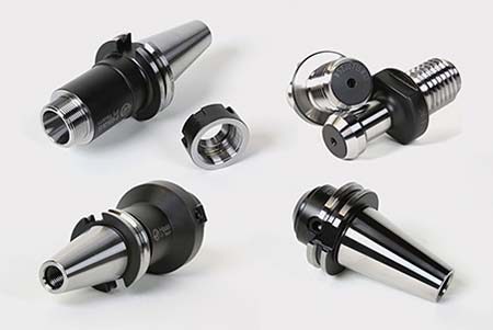
      • End Mill Holders
      • Shell Mill Holders
      • Shrink Fit Holders
      • ER Collet Chucks
      • Milling Chucks & Collets
      • NC Drilling Chucks
      • Pull Studs / Retention Knobs
      • Rotary Tool Holder & Tool Chuck Kits
      • Hydraulic Milling Chucks & Collets
      • Toolholder Attachments & Wrenches
      • Mill Broaching Holders
    • Mill Tooling
      Mill Tooling Shop All
      • Shell Mill Bodies
      • Milling Inserts
      • End Mills
      • Chamfer Mills & Inserts
      • Indexable End Mill Bodies
      • Ball End Mills
      • Chamfer End Mills
      • Roughing End Mills
      • Indexable Ball End Mills & Inserts
      • Shell Mill Kits
      • Chamfer Mill Kits
      • Indexable End Mill Kits
      • Dovetail Cutters
      • Indexable Dovetail Cutters
      • Engraving End Mills
      • Rotary Burrs / Die Grinding Bits
      • Keyseat Cutters
      • Corner Rounding End Mills
      • Slot Mill Bodies
      • CNC Router Bits For Wood
    • Boring Systems
      Boring Systems Shop All
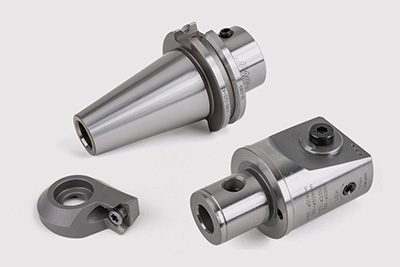
      • Boring Heads & Cartridges
      • Boring Holders & Extensions
    • Mill Workholding
      Mill Workholding Shop All
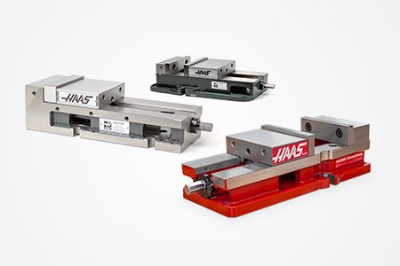
      • Fixed-Jaw Vises
      • Self-Centering Vises
      • Adapter Plates
      • Vise Jaws
      • Vise Mounts & Fixtures
      • Vise Kits
      • Vise Parallels
      • Rotary Vise Kits
      • Fixture Clamps & Rails
      • Automated Workholding Kits
      • Tooling Fixture Subplates
      • Toolmakers' Vises
      • Clamp Force Gauges
      • Collet Fixtures
      • Angle Plates
    • Lathe Toolholding
      Lathe Toolholding Shop All
      • TL & CL Static Turning Holders
      • BOT Static Turning Holders
      • BMT Static Turning Holders
      • Live / Driven Turning Holders
      • Turning Holder Reduction Sleeves / Bushings
      • VDI Static Turning Holders
      • Turning Holder Accessories
    • Lathe Tooling
      Lathe Tooling Shop All
      • Cut-Off Tool Blocks & Blades
      • Cut-Off Tooling Kits
      • Turning Inserts
      • Grooving & Cut-Off Tools
      • Internal (ID) Grooving & Threading Tools
      • Threading Inserts
      • Threading Tools
      • Boring Bars / Internal (ID) Turning Tools
      • External (OD) Turning Tools
      • Cermet Turning Inserts
      • CBN Turning Inserts
      • Haas Notch Grooving & Threading Inserts
      • Haas Notch Grooving & Threading Tools
      • Micro Turning Tools
      • Desktop Lathe Tools
    • Lathe Workholding
      Lathe Workholding Shop All
      • Live Centers
      • Spindle Reduction Sleeves / Liners
      • Quick-Change Collets
      • Quick-Change Collet Chucks
      • 5C Collets
      • 5C Collet Sets
      • Lathe Jaw Boring Rings
      • Lathe Jaws
      • Bar Pullers
      • Scroll Chucks
      • Guide Pins
      • Collet Accessories
    • Package Kits
      Package Kits Shop All
      • Chip Clearing Fan Kits
      • Cutting Tool Kits
      • Indexable End Mill Kits
      • Cut-Off Tool Block & Blade Kits
      • Drill & Tap Kits
      • Indexable Drilling Kits
      • Shell Mill Kits
      • Chamfer Mill Kits
      • Rotary Tool Holder & Tool Chuck Kits
      • Lathe Starter Kits
      • Workholding Kits
      • Rotary Vise Kits
      • Vise Kits
      • 3-Jaw Chuck Kits for Mills
      • Tombstone Kits
      • Reduction Sleeve Kits
      • Automated Workholding Kits
      • Measuring & Inspection Kits
      • Starter Kits
      • Bore Gauge Kits
      • Caliper Kits
      • Indicator Kits
      • Micrometer Kits
    • ER Collets & Chucks
      ER Collets & Chucks Shop All
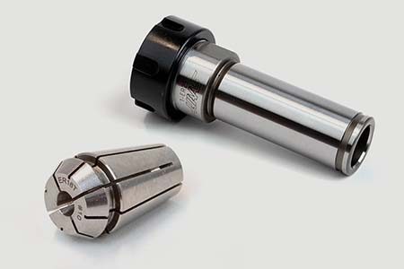
      • ER Straight-Bore Collets
      • ER Sealed Collets
      • ER Tap Collets
      • ER Collet Sets & Accessories
      • ER Collet Chucks
      • Straight Shank ER Collet Chucks
      • Straight Shank Keyless NC Drilling Chucks
    • Holemaking
      Holemaking Shop All
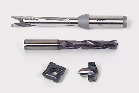
      • Carbide Drills
      • Indexable Drill Bodies
      • Indexable Drill Inserts
      • Modular Drill Bodies
      • Modular Drill Heads
      • Cobalt Drills & Sets
      • Center Drills
      • Reamers
      • Indexable Drilling Kits
      • Spot Drills
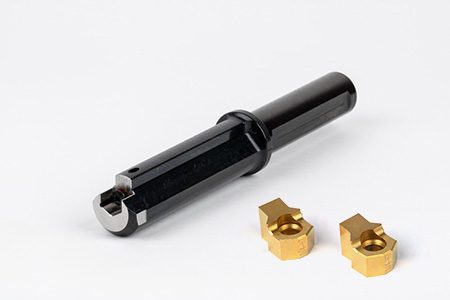
      • Spade Drill Bodies
      • Spade Drill Inserts
      • Countersinks
    • Threading
      Threading Shop All
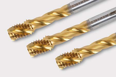
      • Taps
      • Threading Inserts
      • Threading Tools
      • Thread Mills
      • Pipe Taps
      • Drill Tap Kits
    • Broaching
      Broaching Shop All
      • Broaching Tools
      • Broaching Inserts
    • Tombstones
      Tombstones Shop All
      • Tombstones
      • Tombstone Kits
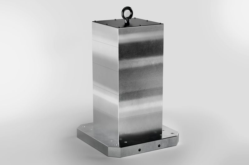
      • Vise Cluster Towers
    • Manual Chucks For Milling
      Manual Chucks For Milling Shop All
      • 3-Jaw Chucks & Mounts for Mills
    • Deburring & Abrasives
      Deburring & Abrasives Shop All
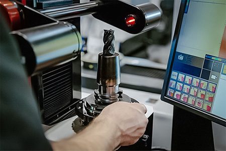
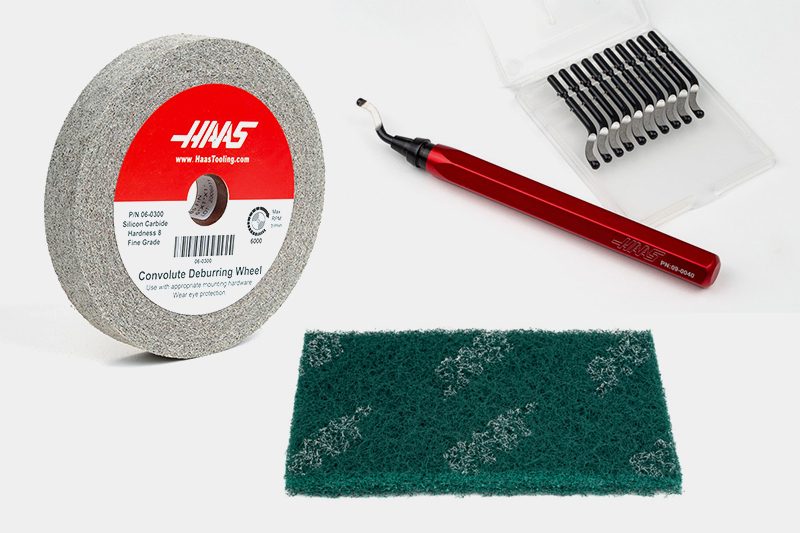
      • Abrasive Pads
      • Deburr Tools
      • Deburr Wheels
      • Abrasive Sheets & Rolls
      • Sharpening / Lapping Stones
    • Tool Presetter & Heat Shrinkers
      Tool Presetter & Heat Shrinkers Shop All
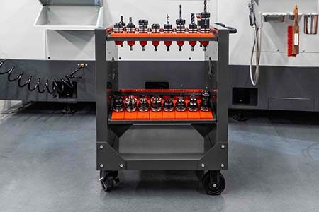
      • Tool Presetting Machines
      • Shrink Fit Machines
    • Tool Storage
      Tool Storage Shop All
      • Tool Carts
      • Tool Tray
      • Tool Bags
    • Machine Maintenance
      Machine Maintenance Shop All
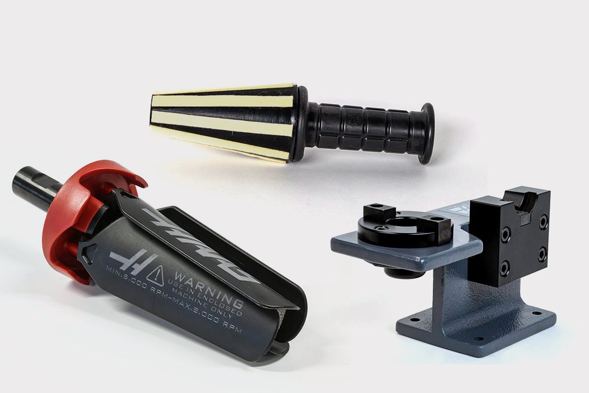
      • Spindle Test Bars
      • Levels
      • Refractometers
      • Machine Additives & Supplies
      • Machine Accessories
      • Machine Maintenance Kits
    • Tooling Accessories
      Tooling Accessories Shop All

      • Spindle & Toolholder Taper Cleaners
      • Haas Shop Lift
      • Toolholder Fixtures
      • CNC Chip Clearing Fans
      • Hammers & Mallets
      • Anti-Fatigue Mats
      • Layout Tools
      • Wrenches
      • Magnetic Tools
      • Torque Screwdrivers
      • Hand Cutting Tools
      • Shop Stools
      • Lifting Magnets
      • Safety Apparel
      • Cutting Tool Sharpeners
    • Apparel & Accessories
      Apparel & Accessories Shop All
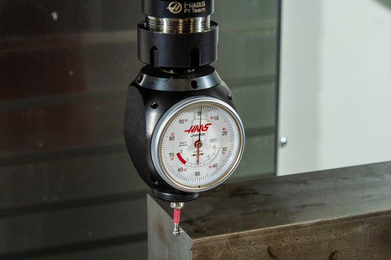
      • Accessories
      • Apparel
    • HAAS TOOLING QUICK LINKS
      NEW PRODUCTS NEW PRODUCTS NEW PRODUCTS NEW PRODUCTS
      MOST POPULAR MOST POPULAR
      TOOLING PROMOS TOOLING PROMOS
      FINANCING & OPEN TERMS FINANCING & OPEN TERMS PAY BY INVOICE PAY BY INVOICE
      FAQs FAQs
      KITS CREATED FOR YOU KITS CREATED FOR YOU
  • Haas Service Parts Main Menu
      Automatic Pallet Changer Lathe Turret Tool Changer Chip Management Coolant Counterbalance Electrical Cabinet Enclosure Hydraulics Lubrication Maintenance Pendant Probing Rotary Spindle Tailstock
    • Haas Service Parts
    • Automatic Pallet Changer
      Automatic Pallet Changer Shop All
      • HMC - Automatic Pallet Changer
      • VMC - Automatic Pallet Changer
    • Lathe Turret
      Lathe Turret Shop All
      • Lathe - Turret
      • Live Tooling
    • Tool Changer
      Tool Changer Shop All
      • Side Mount
      • Umbrella
    • Chip Management
      Chip Management Shop All
      • Multi Auger
      • Single Auger
    • Coolant
      Coolant Shop All
      • Auxiliary Filter
      • HPC-300 (Lathe)
      • HPC-1000 (Lathe)
      • Oil Skimmer
      • Standard Coolant
      • TSC-300 (Mill)
      • TSC-1000 (Mill)
      • Coolant Refill
      • Loc-Line
    • Counterbalance
      Counterbalance Shop All
      • Charge & Discharge Hose
    • Electrical Cabinet
      Electrical Cabinet Shop All
      • Fans
      • Filters
      • Upgrade Kits
    • Enclosure
      Enclosure Shop All
      • Accessories
      • Air Nozzle
      • Decals
      • Door Bumpers
      • Lighting
      • Windows, Gaskets, & Weather Strip
      • Chip & Coolant Management
    • Hydraulics
      Hydraulics Shop All
      • Filters
      • Gauges
      • Heat Exchanger
      • Hoses
    • Lubrication
      Lubrication Shop All
      • Bijur Mechanical Lubrication
      • Minimum Lubrication
    • Maintenance
      Maintenance Shop All
      • Grease, Oil, & Sealants
    • Pendant
      Pendant Shop All
      • Floppy Disk & USB
      • Keypad
      • Keys
      • Lens
      • Gaskets & Seals
    • Probing
      Probing Shop All
      • Mill Probing
      • Lathe Tool Presetter
    • Rotary
      Rotary Shop All
      • Rotary Gaskets & Seals
    • Spindles
      Spindles Shop All
      • Couplings
      • Gaskets & Seals
      • Spindle Motor Drive
      • Gearbox Drive
      • Tool Release Piston
    • Tailstock
      Tailstock Shop All
      • Handles
×

Search Results

Web Pages

Images

    • <
    • 1
    • >
MyHaas Welcome,
!
Haas Tooling Guest Order History MyHaas/HaasConnect Sign In Register Haas Tooling My Account Order History Return History MyHaas/HaasConnect Sign Out Welcome, My Machines Latest Activity My Quotes My Account My Users Sign Out
Find Your Distributor
  1. Select Language
    1. English
    2. Deutsch
    3. Español - España
    4. Español - México
    5. Français
    6. Italiano
    7. Português
    8. Český
    9. Dansk
    10. Nederlands
    11. Magyar
    12. Polski
    13. Svenska
    14. Türkçe
    15. 中文
    16. Suomi
    17. Norsk
    18. الإنجليزية
    19. български
    20. Hrvatski
    21. Ελληνικά
    22. Română
    23. Slovenský
    24. Slovenščina
    25. 한국어
    26. 日本語
    27. Українська
×

Search Results

Web Pages

Images

    • <
    • 1
    • >

11 - Mill - Operation

Mill Operator's Manual


  • 0 - Mill - Table of Contents
  • 1 - Mill - Introduction
  • 2 - Mill - Legal Information
  • 3 - Mill - Safety
  • 4 - Mill - Control Pendant
  • 5 - Mill - Control Display
  • 6 - Mill - Device Manager
  • 7 - Mill - TouchScreen Feature
  • 8 - Mill - Part Setup
  • 9 - Mill - Umbrella Tool Changer
  • 10 - Mill - SMTC
  • 11 - Mill - Operation
  • 12 - Mill - Programming
  • 13 - Mill - Macros
  • 14 - Mill - Control Icons
  • 15 - Mill - Remote Jog Handle
  • 16 - Mill - Options Programming
  • 17 - Mill - G-Codes
  • 18 - Mill - M-Codes
  • 19 - Mill - Settings
  • 20 - Mill - Other Equipment

Go To :

  • 11.1 Power On
  • 11.2 Screen Capture
  • 11.3 Program Search
  • 11.4 Safe Run Mode
  • 11.5 Run-Stop-Jog Continue
  • 11.6 Graphics Mode
  • 11.7 Broken Tool Detection
  • 11.8 Tooling
  • 11.9 Advanced Tool Management

11.1 Power On

Machine Power-On

This section tells you how to power-on a new machine for the first time.

  • Press POWER ON until you see the Haas logo on the screen. After a self-test and boot sequence, the display shows the startup screen.

    The startup screen gives basic instructions to start the machine. Press CANCEL to dismiss the screen.

  • Turn EMERGENCY STOP to the right to reset it.
  • Press RESET to clear the startup alarms. If you cannot clear an alarm, the machine may need service. Contact your Haas Factory Outlet (HFO) for assistance.
  • If your machine is enclosed, close the doors.
    WARNING: Before you do the next step, remember that automatic motion begins immediately when you press POWER UP. Make sure the motion path is clear. Stay away from the spindle, machine table, and tool changer.
  • Press POWER UP.
    After the first POWER UP, the axes move toward their home positions. The axes then move slowly until the machine finds the home switch for each axis. This establishes the machine home position.

Press any of the following:

  • CANCEL to dismiss the screen.
  • CYCLE START to run current program.
  • HANDLE JOG for manual operation.

Spindle Warm-Up

If your machine’s spindle has been idle for more than (4) days, run the spindle warm-up program before you use the machine. This program brings the spindle up to speed slowly to distribute the lubrication and let the spindle reach a stable temperature.

Your machine includes a 20-minute warm-up program (O09220) in the program list. If you use the spindle at consistent high speeds, you should run this program every day.

11.2 Screen Capture

Screen Capture

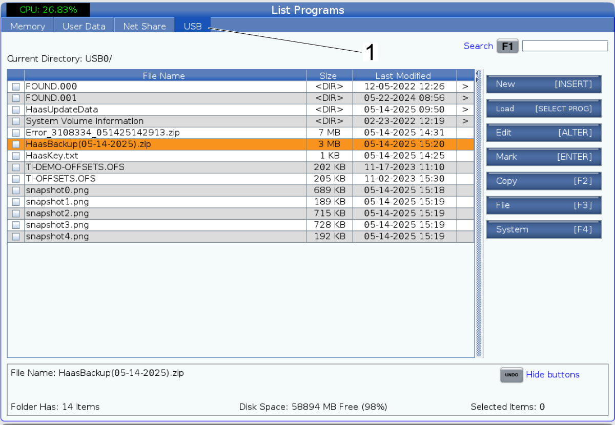
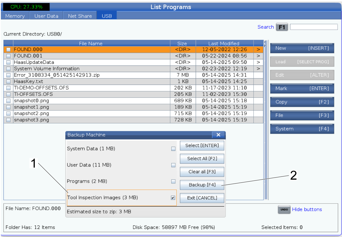
The control can capture and save an image of the current screen to an attached USB device or the User Data memory.

Enter a filename if desired. If no filename is entered, the system will use the default filename (see note).

Press SHIFT.

Press F1.

NOTE: The control uses the default filename snapshot#.png. The # starts from 0 and increments each time you capture a screen. This counter resets at power off. Screen captures that you take after a power cycle overwrite previous screen captures that have the same filename on the User Data memory.

Result: 

The control saves the screen capture to your USB device or control memory. The message Snapshot saved to USB or Snapshot saved to User Data appears when the process finishes.

Error Report

The control can generate an error report that saves the state of the machine that is used for analysis. This is useful when helping the HFO troubleshoot an intermittent problem.

  1. Press SHIFT.
  2. Press F3.

NOTE: Be sure to always generate the error report with the alarm or the error is active.

Result: 

The control saves the error report to your USB device or control memory.The error report is a zip file that includes a screen capture, the active program, and other information used for diagnostics. Generate this error report when an error or an alarm occurs. E-mail the error report to your local Haas Factory Outlet.

11.3 Program Search

Basic Program Search

You can use this function to quickly find code in a program.

NOTE: This is a quick-search function that finds the first match in the search direction that you specify. You can use the Editor for a more full-featured search. Refer to Chapter 6.5 for more information on the Editor search function.

NOTE: This is a quick-search function that finds the first match in the search direction that you specify. You can use the Editor for a more full-featured search. Refer to The Search Menu for more information on the Editor search function.

  1. Type the text you want to find in the active program.
  2. Press the UP or DOWN cursor arrow key.

Result: 

The UP cursor arrow key searches from the cursor position to the start of the program. The DOWN cursor arrow key searches to the end of the program. The control highlights the first match.

NOTE: Putting your search term within parentheses (), will search only within comment lines.

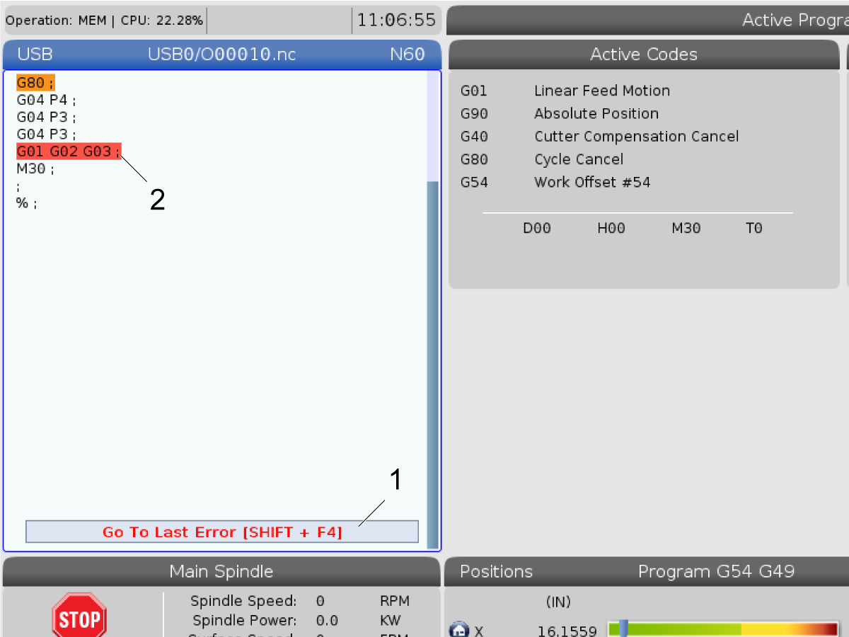
Locate the Last Program Error

Starting in software version 100.19.000.1100 the control can find the last error in a program.

Press SHIFT + F4 to display the last line of G-code that generated the error.

11.4 Safe Run Mode

Safe Run Mode

The purpose of Safe Run is to reduce damage to the machine in the event of a crash. It does not prevent crashes, but it raises an alarm sooner and backs off from the crash location.

NOTE: The Safe Run feature is available starting in software version 100.19.000.1300.

 NOTE: If the machine is equipped with a spindle head accelerometer, and when safe mode is enabled and active (ie. during rapids), the accelerometer alarm behavior will be suppressed so the machine can do the normal back off behavior, then the 9941 Alarm will generate.  The G force value will still be recorded at the time of the event.

Safe Run Supported Machines

  • VF-1 through VF-5
  • VM-2/3
  • UMC-500/750/1000
  • All DM’s
  • All DT’s
  • All TM’s
  • ST-10 through ST-35

Common causes for crashes are:

  • Incorrect tool offsets.
  • Incorrect work offsets.
  • Wrong tool in the spindle.

NOTE: The Safe Run feature will only detect a crash in handle jog and rapid (G00), it will not detect a crash in a feed move.

Safe Run does the following:

  • Slow down the speed of the motion.
  • Increases the position error sensitivity.
  • When a crash is detected, the control will immediately reverse the axis by a small amount. This will prevent the motor from continuing to drive into the object it has crashed into as well as relieve pressure from the crash itself. After Safe Run has detected a crash, you should be able to easily fit a piece off paper between the two surfaces that crashed.

NOTE: Safe Run is intended for running a program for the first time after writing or changing it. Is it not recommended to run a reliable program with Safe Run, as it increases cycle time significantly. The tool may break and the work piece may still be damaged in a crash.

Safe Run is active during jogging as well. Safe Run can be used during job setup to protect against accidental crashes due to operator error.

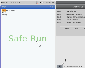
If your machine supports Safe Run, you will see a new icon in MDI with the text F3 Activate Safe Run [1]. Press F3 to turn Safe Run on/off. Safe Run Active state is noted by a water mark [2] in the program panel.

It is only active during rapid motions. Rapid motions include G00, Home G28, moving to tool changes, and the non-machining motions of canned cycles. Any machining motion such as a feed or tap will not have safe mode active.

Safe Run is not active during feeds due to the nature of crash detection. Cutting forces cannot be discerned from crashes.

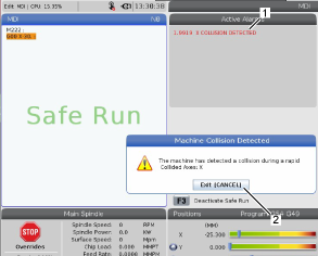
When a crash is detected, all motion is brought to a stop, an alarm [1] is generated, and a popup [2] is generated letting the operator know that a crash was detected, and which axis it was detected on. This alarm can be cleared by reset.

In certain cases the pressure against the part may not have been relieved by the Safe Run back-off. In the worse case, an additional crash may be generated after you have reset the alarm. If this happens, turn Safe Run off and jog the axis away from the crash location.

11.5 Run-Stop-Jog Continue

Run-Stop-Jog-Continue

This feature lets you stop a running program, jog away from the part, and then start the program again.

  1. Press FEED HOLD.

    Axis motion stops. The spindle continues to turn.

  2. Press X, Y, Z, or an installed Rotary Axis (A for A Axis, B for B Axis, and C for C Axis), then press HANDLE JOG. The control stores the current X, Y, Z, and rotary axes positions.
  3. The control gives the message Jog Away and displays the Jog Away icon. Use the jog handle or jog keys to move the tool away from the part. You can start or stop the spindle with FWD, REV, or STOP. You can command optional Through Spindle Coolant on and off with the AUX CLNT key (you must stop the spindle first). Command optional Through Tool Air Blast on and off with SHIFT + AUX CLNT keys. Command Coolant on and off with the COOLANT key. Command the Auto Air Gun / Minimum Quantity Lubrication options with SHIFT + COOLANT keys. You can also release the tool to change inserts.

    CAUTION: When you start the program again, the control uses the previous offsets for the return position. Therefore, it is unsafe and not recommended to change tools and offsets when you interrupt a program.

  4. Jog to a position as close as possible to the stored position, or to a position where there is an unobstructed rapid path back to the stored position.

  5. Press MEMORY or MDI to return to run mode. The control gives the message Jog Return and displays the Jog Return icon. The control continues only if you return to the mode that was in effect when you stopped the program.

  6. Press CYCLE START. The control rapids X, Y, and rotary axes at 5% to the position where you pressed FEED HOLD. It then returns the Z Axis. If you press FEED HOLD during this motion, axis motion pauses and the control gives the message Jog Return Hold. Press CYCLE START to resume the Jog Return motion. The control goes into a feed hold state again when the motion is finished.

    CAUTION: The control does not follow the same path that you used to jog away.

  7. Press CYCLE START again and the program resumes operation.

    CAUTION: If Setting 36 is ON, the control scans the program to make sure the machine is in the correct state (tools, offsets, G- and M-codes, etc.) to safely continue the program. If Setting 36 is OFF, the control does not scan the program. This can save time, but it could cause a crash in an unproven program.

11.6 Graphics Mode

Graphics Mode

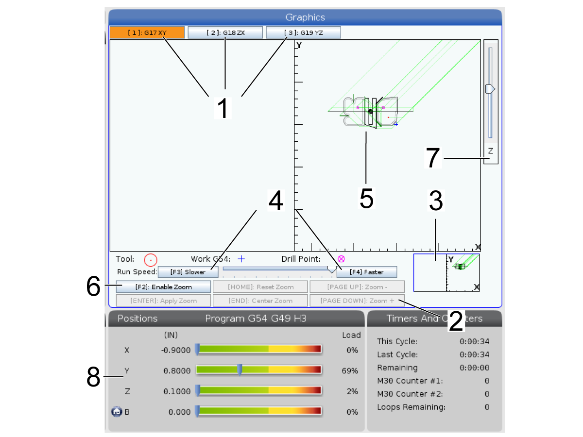
A safe way to troubleshoot a program is to press GRAPHICS to run it in graphics mode. No movement occurs on the machine, instead the movement is illustrated on the screen.

1) Axis Planes Press 1 to view the graphics in G17 plane, press 2 forG18 plane or press 3 to view in G19 plane.

2) Key Help Area The lower-left part of the graphics display pane is the function key help area. This area shows you the function keys that you can use, and a description of what they do.

3) Locator Window The lower-right part of the pane displays the simulated machine table area, and it shows where the simulated view is zoomed and focused.

4) Graphics Speed Press f3 or f4 to run the desired graphics speed.

5) Tool Path Window The large window in the center of the display gives a simulated view of the work area. It displays a cutting tool icon and simulated tool paths.

NOTE: Feed motion appears as a black line. Rapid moves appear as a green line. Drill cycle locations appear with an X.

NOTE: If Setting 253 is ON, the tool diameter is shown as a thin line. If it is OFF, the tool diameter specified in the Tool Offsets Diameter Geometry table is used.

6) Zoom Press F2 to display a rectangle (zoom window) that shows the area that the zoom operation will move to. Use PAGE DOWN to decrease the size of the zoom window (zoom in), and use PAGE UP to increase the size of the zoom window (zoom out). Use the cursor arrow keys to move the zoom window to the location you want to zoom, and press ENTER to complete the zoom. The control scales the tool path window to the zoom window. Run the program again to display the tool path. Press F2 and then HOME to expand the Tool Path window to cover the entire work area.

7) Z-Axis Part Zero Line The horizontal line on the Z-Axis bar at the top-right corner of the graphics screen gives the position of the current Z-axis work offset plus the length of the current tool. While a program simulation runs, the shaded portion of the bar indicates the depth of the simulated Z-Axis motion relative to the Z-Axis work zero position.

8) Position Pane The position pane displays axis locations just as it would during a live part run.

11.7 Broken Tool Detection

Recently Updated

Broken Tool Detection - Operation


Introduction

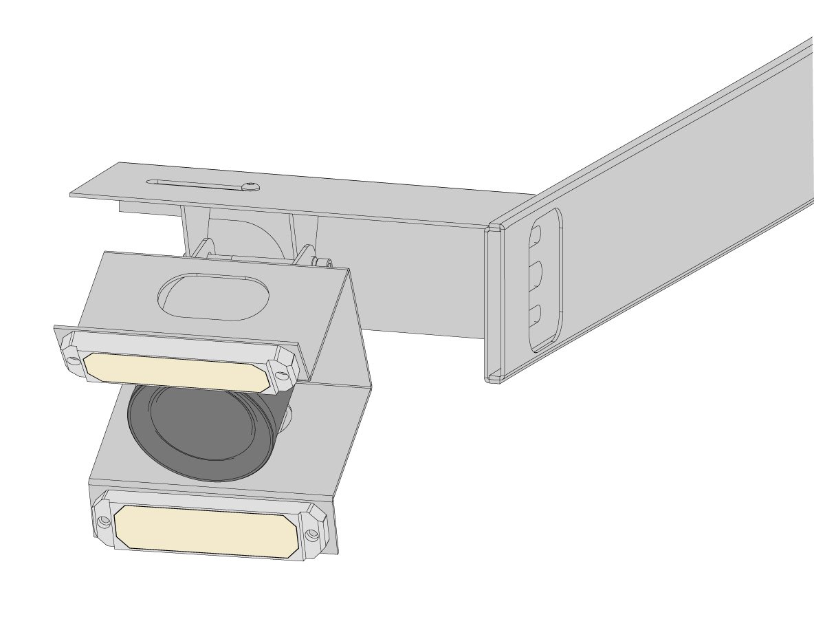
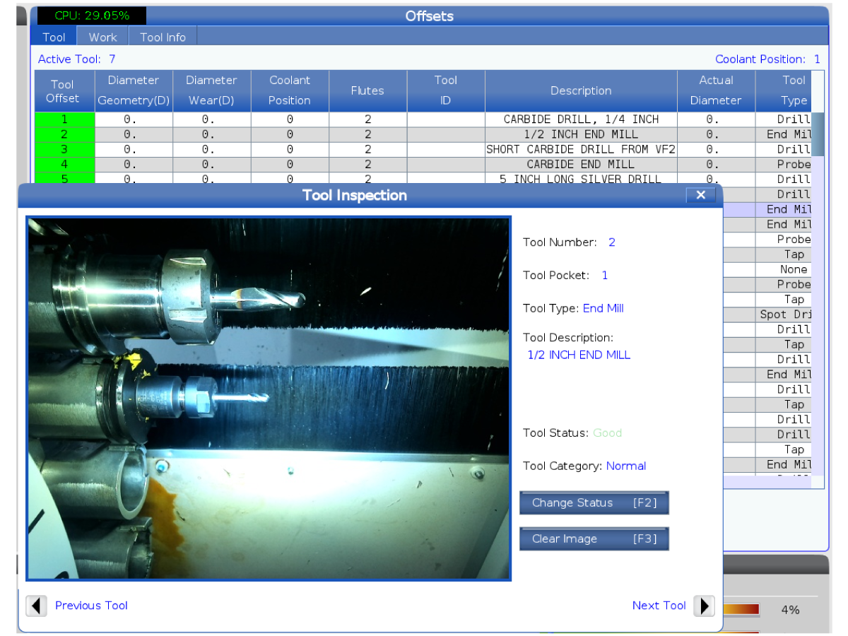
The Broken Tool Detection (BTD) is a feature that captures an image & detects the length of a tool before and after use. With a noticeable difference in length, then ALARM 9300 Broken Tool will be triggered forcing the BTD tab to pop up with before and after images.

This procedure will show how to operate a machine equipped with Broken Tool Detection system.

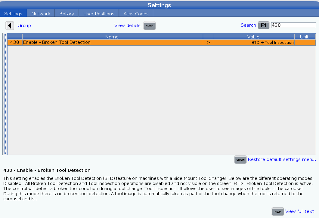
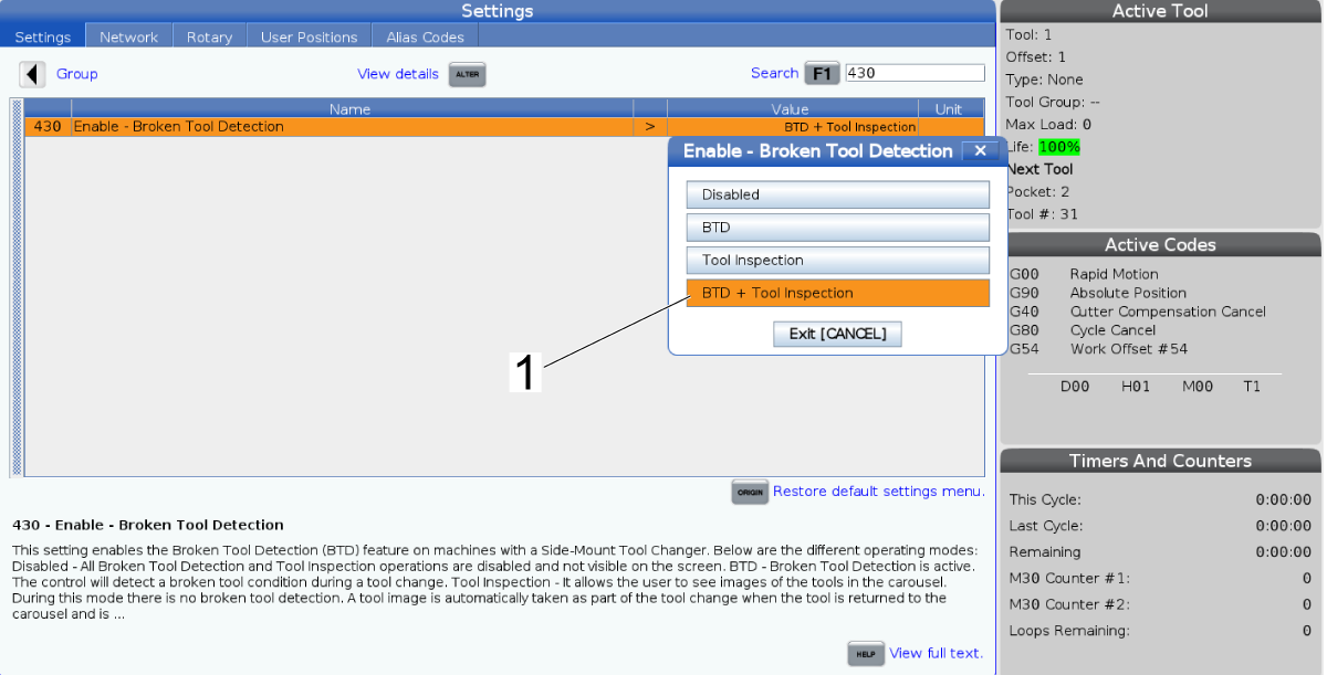
IMPORTANT: With the machine in service mode, make sure that Setting 430 is set to ON.

 NOTE: For more information on the Broken Tool Detection feature, refer to the Broken Tool Detection - Troubleshooting Guide.

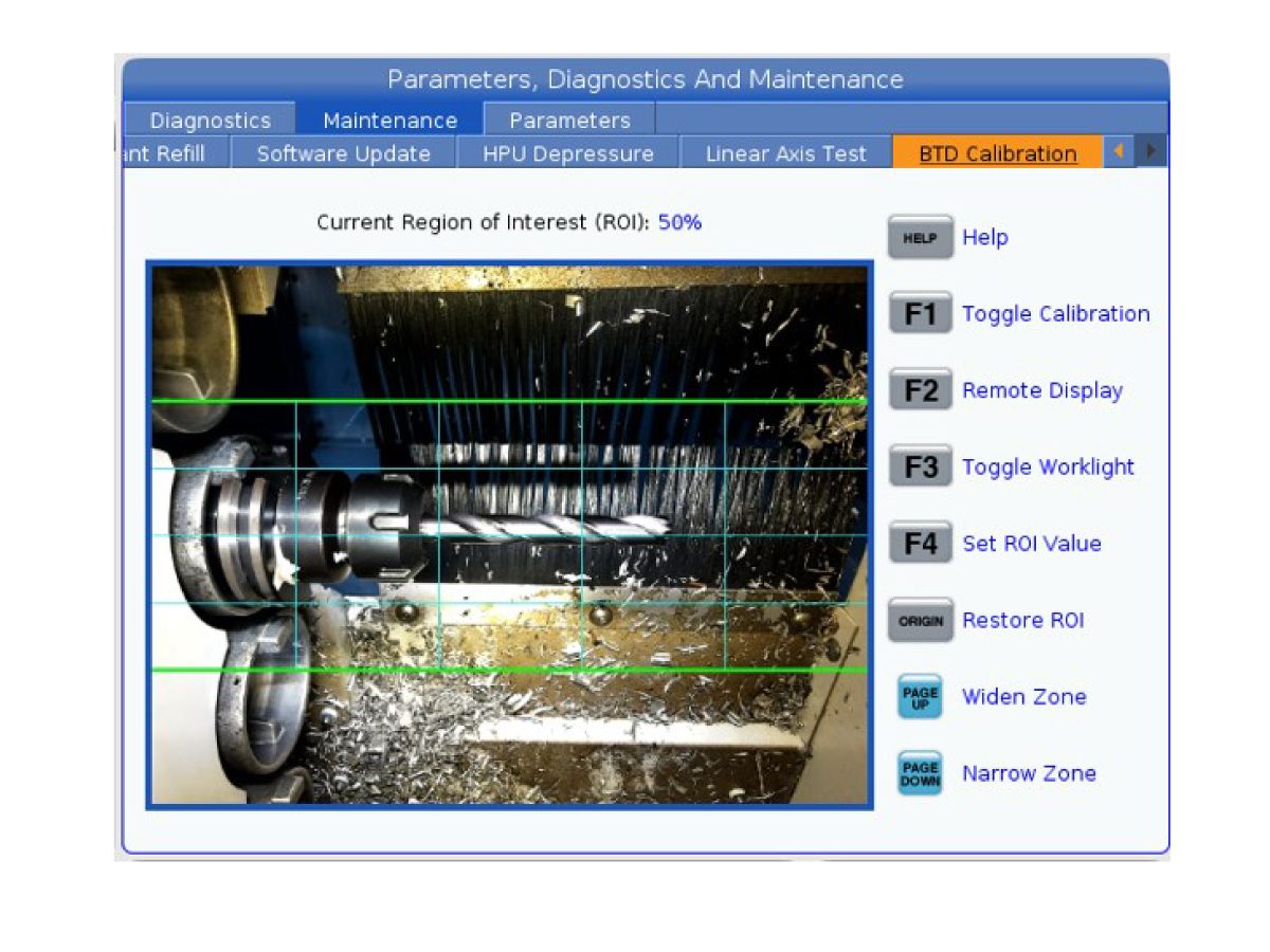
BTD Calibration

The BTD Calibration page can be found under Diagnostic > Maintenance > BTD Calibration. 

This BTD Calibration page is accessible to all. This tab shows a live feed of the BTD camera—either on the machine's screen by pressing [F1] or on the remote display by pressing [F2]. 

When viewing the camera live feed, this page can also be used to set the Value Region of Interest (ROI) Value. This value sets the size of the area for whatever the camera is detecting by pressing [PAGE UP] or [PAGE DOWN]. This detected area is where the tool is expected to be—try aligning the tool with the center ROI line. 

NOTE: It is important to finalize the camera mounting alignment first, before finalizing the ROI Value. To get the default ROI Value, press [ORIGIN] to return back to a ROI Value of 50%. 


Tool Table

The Tool Table page [1] can be found under Current Commands > Tools > Tool Table.

Under the Tool Table, mark the tools that will be checked with the Broken Tool Detection system by pressing [F2]. Now, the Broken Tool Detection will run on those selected tools before and after use such as a G01 with movement.

NOTE: The Broken Tool Detection system only runs during a tool change within a program (M06), not during manual tool changes [ATC FWD].

Note: The BTD Tab [2] under Current Commands > Tools > BTD will only show up when there is a broken tool detected.

11.8 Tooling

Introduction

This section describes tool management in the Haas control: commanding tool changes, loading tools into holders, and Advanced Tool Management.

Tool Holders

There are several different spindle options for Haas mills. Each of these types requires a specific tool holder. The most common spindles are 40- and 50-taper. 40-taper spindles are divided into two types, BT and CT; these are referred to as BT40 and CT40. The spindle and tool changer in a given machine are capable of holding only one tool type.

Tool Holder Care:

  1. Make sure that tool holders and pulls studs are in good condition and tightened together securely or they may stick in the spindle.
  2. Clean the tool holder taper body (the part that goes into the spindle) with a lightly oiled rag to leave a film, which helps prevent rusting.

Tool Holder Assembly, 40-Tape CT Example

  • Pull Stud [1]
  • Tool (Endmill) [2]

Pull Studs:

A pull stud (sometimes called a retention knob) secures the tool holder into the spindle. Pull studs are threaded into the top of the tool holder and are specific to the type of spindle. Refer to the 30, 40, and 50-taper spindle and tooling information on the Haas Service website for descriptions of the pull studs you need.

 CAUTION: Do not use short-shaft or pull studs with a sharp right-angle (90-degree) head; they will not work and will cause serious damager to the spindle.

Tool Usage Display

The Tool Usage tab contains information about the tools used in a program. This display will tell you information about each tool used in a program and statistics about each time it was used. It starts to collect information when user Main program start and clear information when meet codes M99, M299, M199.

To get to the Tool Usage display press [CURRENT COMMANDS] then go to Tools and then Tool Usage tab.

  1. Start Time - When the tool was inserted to the spindle.

  2. Total Time - The total time the tool has been in the spindle.

  3. Feed time - Tool usage time.

  4. Load% - The maximum load of the Spindle during a tool usage.

     NOTE: This value is retrieved every second. The actual load compared to the recorded may vary.

  5. Feed/Total time - A graphic representation of the feed time of the tool over the total time.
  6. Engagement:

    • Black Bar- The tool usage versus another tools.

    • Gray Bar - This bar shows how long the tool was used in this usage related to other usages.

Macros Interface

You can use these macros variables to set and collect the tool usage data

Macro variable Function
#8608 Set the desired tool
#8609 Current tool number - if result more 0 (the tool was used)
#8610 Total time mentioned in #8609 tool number
#8611 Feed time of mentioned tool number
#8612 Total time
#8605 Next usage of a tool
#8614 Usage start time stamp
#8615 Usage Total time
#8616 Usage Feed time
#8617 Usage Max load

Tool Info Display

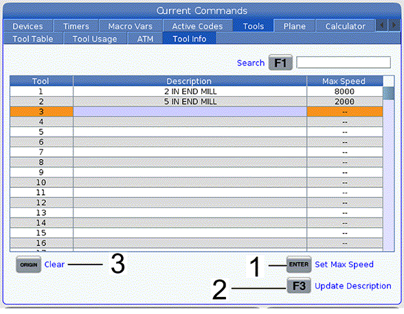
The Tool Info display tab allows user to specify maximum RPM for a tool. You can also specify a tool description in the same table.

To get to the Tool Info display press [CURRENT COMMANDS] then go to Tools and then Tool Info tab.

  1. To set the max speed for a tool highlight the tool row and type in the desired max speed and press [ENTER] .

  2. To set the tool description highlight the tool row and type in the description and press [F3] .

  3. To clear the tool max speed or description press [ORIGIN] .

Tool Table

This section tells you how to use the tool table to give the control information about your tools.

 NOTE: If your machine has an umbrella-style tool changer, you will not use the tool pocket table.

Tool Table Display:

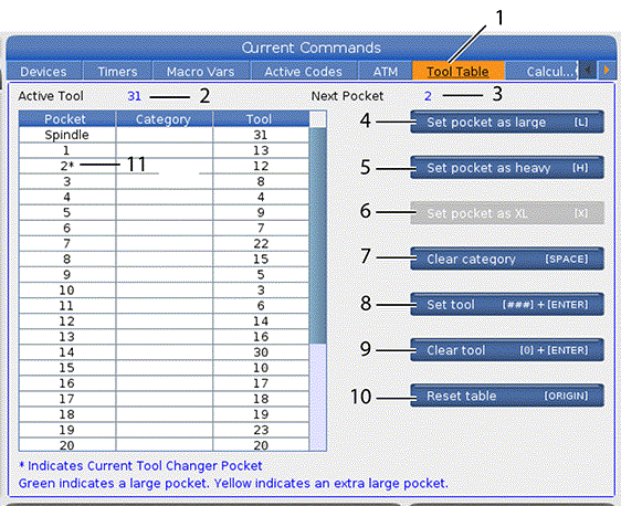
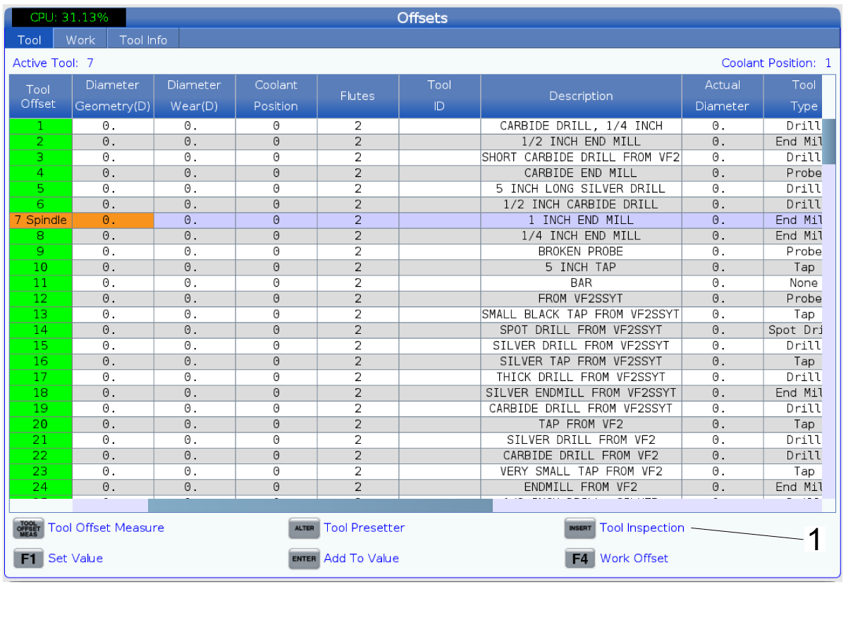
  • To access the Tool Pocket Table, press [CURRENT COMMANDS] and choose the Tool Table tab [1].
  • Active Tool [2] - Tells you the tool number that is installed in the spindle
  • Active Pocket [3] - Shows you the next pocket number.
  • Set pocket as large [L] [4] - Use this flag when a large tool has a diameter of greater than 3" for 40-tape machines and greater than 4" for 50-taper machines. Scroll to the pocket of interest and press [L] to set the flag.

     CAUTION: You cannot place a large tool in the tool changer if one or both of the surrounding pockets already contain tools. Doing so causes the tool changer to crash. Large tools must have the surrounding pockets empty. However, large tools can share adjoining empty pockets.
  • Set pocket as heavy [H] [5] - Use this flag when a Heavy, Small Diameter 40-taper tool (4 lb or heavier) or a 50-taper tool (12 lb or heavier) is loaded into the spindle. Scroll to the pocket of interest and press [H] to set the flag.
  • Set pocket as XL [X] [6] - Use this flag when two adjacent pockets are each side of the tool are needed. Scroll to the pocket of interest and press [X] to set the flag.

     NOTE: This option only appears if your machine is a 50-taper.

  • Clear category [SPACE] [7] - Highlight the desired tool and press [SPACE] to clear the flag.
  • Set tool [###] + [ENTER] [8] - Highlight the desired pocket and type in the tool number along with [ENTER] to set the desired tool number.

     NOTE: You cannot assign a tool number to more than one pocket. If you enter a tool number that is already defined in the tool pocket table, you see an Invalid tool error.

  • Clear tool [0] + [ENTER] [9] - Highlight the desired pocket and press [0] along with [ENTER] to clear out the tool number.
  • Reset table [Origin] [11] - Press [ORIGIN] with the cursor in the center column to use the [ORIGIN] menu. This menu lets you:  
    • Sequence All Pockets - Makes all of the tool numbers sequential based on their pocket location, starting with 1.

    • Zero All Pockets - Removes all of the tool numbers from all of the pocket numbers.

    • Clear Category Flags - Removes the category designations from all of the tools.

11.9 Advanced Tool Management

Introduction

Advanced Tool Management (ATM) lets you set up groups of duplicate tools for the same or a series of jobs.

ATM classifies duplicate or backup tools into specific groups. In your program, you specify a group of tools instead of a single tool. ATM tracks the tool use in each tool group and compares it to your defined limits. When a tool reaches a limit, the control considers it “expired.” The next time your program calls that tool group, the control chooses a non-expired tool from the group.

When a tool expires:

  • The beacon will flash.

  • ATM puts the expired tool in the EXP group

  • Tool groups that contain the tool appear with a red background.

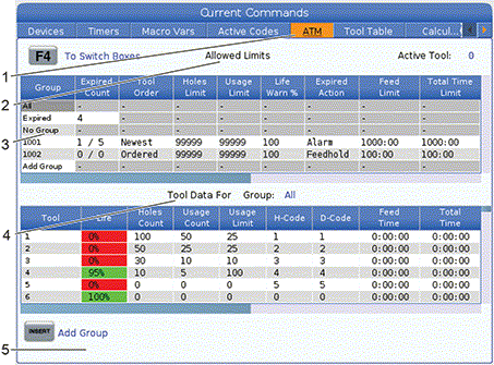
To use ATM, press [CURRENT COMMANDS] , and then select ATM in the tabbed menu. The ATM window has two sections: Allowed Limits and Tool Data.

Advanced Tool Management Window:

  • Active window label [1]
  • Allowed limits window [2]
  • Tool group window [3]
  • Tool data window [4]
  • Help text [5]

Allowed Limits

This table gives data about all of the current tool groups, including default groups and user-specified groups. ALL is a default group that lists all of the tools in the system. EXP is a default group that lists all of the tools that are expired. The last row in the table shows all of the tools that are not assigned to tool groups. Use the cursor arrow keys or [END] to move the cursor to the row and see these tools.

For each tool group in the ALLOWED LIMITS table, you define limits that determine when a tool expires. The limits apply to all tools assigned to this group. These limits affect every tool in the group.

The columns in the ALLOWED LIMITS table are:

  • GROUP - Displays the tool group’s ID number. this is the number you use to specify the tool group in a program.

  • EXP # - Tells you how many tools in the group are expired. If you highlight the ALL row, you see a list of all of the expired tools in all groups.

  • ORDER - Specifies the tool to use first. If you select ORDERED, ATM uses the tools in tool number order. You can also have ATM automatically use the NEWEST or OLDEST tool in the group.

  • USAGE - The maximum number of times the control can use a tool before it expires.

  • HOLES - The maximum number of holes a tool is allowed to drill before it expires.

  • WARN - The minimum value for tool life remaining in the group before the control gives a warning message.

  • LOAD - The allowed load limit for tools in the group before the control does the ACTION that the next column specifies.

     WARNING: Load limit should not be used for applications where spindle speed and feed change rapidly. For example, tapping or constant surface speed.

  • ACTION - The automatic action when a tool reaches its maximum tool load percentage. Highlight the tool action box to change and press [ENTER] . Use the [UP] and [DOWN] cursor keys to select the automatic action from the pull down menu ( ALARM, FEEDHOLD, BEEP, AUTOFEED, NEXT TOOL).

  • FEED - The total amount of time, in minutes, that the tool can be in a feed.

  • TOTAL TIME - The total amount of time, in minutes, that the control can use a tool.

Tool Data

This table gives information about each tool in a tool group. To look at a group, highlight it in the ALLOWED LIMITS table, and then press [F4] .

  • TOOL# - Shows the tool numbers used in the group.

  • LIFE - The percentage of life left in a tool. This is calculated by the CNC control, using actual tool data and the allowed limits the operator entered for the group.

  • USAGE - The total number of times that a program has called the tool (number of tool changes).

  • HOLES - The number of holes the tool has drilled/ tapped/ bored.

  • LOAD - The maximum load, in percent, exerted on the tool. This limit should not be used for applications where spindle speed and feed change rapidly. For example tapping or constant surface speed.

    WARNING: Load limit should not be used for applications where spindle speed and feed change rapidly. For example tapping or constant surface speed.

  • LIMIT - The maximum load allowed for the tool

  • FEED - The amount of time, in minutes, the tool has been in a feed.

  • TOTAL - The total amount of time, in minutes, the tool has been used.

  • H-CODE - The tool-length code to use for the tool. You can edit this only if Setting 15 is set to OFF.

  • D-CODE - The diameter code to use for the tool.

    NOTE: By default, the H- and D-codes in Advanced Tool Management are set to equal the tool number that is added to the group.

Tool Group Setup

To add a tool group: 

  1. Select the ALLOWED LIMITS table.
  2. Use the cursor arrow keys to highlight an empty row.
  3. Type the group identification number (between 1000 and 2999) that you want to use for the new tool group.
  4. Press [ENTER].

Manage Tools in a Group

To add, change, or delete a tool in a group: 

  1. Highlight the group you want to work with in the ALLOWED LIMITS table. 
  2. Press [F4] to switch to the TOOL DATA table. 
  3. Use the cursor arrow keys to highlight an empty row. 
  4. Type an available tool number between 1 and 200. 
  5. Press [ENTER]. 
  6. To change a tool number assigned to a group, use the cursor keys to highlight the tool number you want to change. 
  7. Type a new tool number
     NOTE: You can type 0 if you want to delete the tool from the tool group.
  8. Press [ENTER].

Tool Group Usage

To use a tool group in a program, substitute the tool group ID number for the tool number and for the H-codes and D-codes in the program. Refer to this program for an example of the program format.

Example:

    % O30001 (Tool change ex-prog);

    (G54 X0 Y0 is top right corner of part) ;

    (Z0 is on top of the part) ;

    (Group 1000 is a drill) ;(T1000 PREPARATION BLOCKS) ;

    T1000 M06 (Select tool group 1000) ;

    G00 G90 G40 G49 G54 (Safe startup) ;

    X0 Y0 (Rapid to 1st position) ;

    S1000 M03 (Spindle on CW) ;

    G43 H1000 Z0.1 (Tool group offset 1000 on) ;

    M08 (Coolant on) ;

    (T1000 CUTTING BLOCKS) ;

    G83 Z-0.62 F15. R0.1 Q0.175 (Begin G83);

    X1.115 Y-2.75 (2nd hole);

    X3.365 Y-2.87 (3rd hole);

    G80 ;

    G00 Z1. M09 (Rapid retract, coolant off) ;

    G53 G49 Z0 M05 (Z home, spindle off) ;

    M01 (Optional stop) ;

    (T2000 PREPARATION BLOCKS) ;

    T2000 M06 (Select tool group 2000) ;

    G00 G90 G40 G49 G54 (Safe startup) ;

    G00 G54 X0.565 Y-1.875 (Rapid to 4th position) ;

    S2500 M03 (Spindle on CW) ;

    G43 H2000 Z0.1 (Tool group offset 2000 on) ;

    M08 (Coolant on) ;

    (T2000 CUTTING BLOCKS) ;

    G83 Z-0.62 F15. R0.1 Q0.175 (Begin G83);

    X1.115 Y-2.75 (5th hole) ;

    X3.365 Y2.875 (6th hole) ;

    (T2000 COMPLETION BLOCKS) ;

    G00 Z0.1 M09 (Rapid retract, Coolant off) ;

    G53 G49 Z0 M05 (Z home, Spindle off) ;

    G53 Y0 (Y home) ;

    M30 (End program) ;

    %

Advanced Tool Management Macros

Advanced Tool Management (ATM) can use macros to obsolete a tool within a tool group. Macros 8001 to 8200 represent tools 1 through 200. You can set one of these macros to 1 to expire a tool. For example:

8001 = 1 (this expires tool 1)

8001 = 0 (this makes tool 1 available)

Macro variables 8500 - 8515 enable a G code program to obtain tool group information. When you specify a tool group ID number with macro 8500, the control returns the tool group information in macro variables #8501 through #8515. Refer to the variables #8500 - #8515 in the Macros chapter for the macro variable data label information.

Macro variables #8550 - #8564 let a G-code program obtain information about individual tools. When you specify an individual tool ID number with macro #8550, the control returns the individual tool information in macro variables #8551 - #8564. You can also specify an ATM group number with macro 8550. In this case, the control returns the individual tool information for the current tool in the specified ATM tool group in macro variables 8551 - 8564. Refer to the description for variables #8550 - #8564 in the Macros chapter. The values in these macros provide data that is also accessible from macros starting at 1601, 1801, 2001, 2201, 2401, 2601, 3201, and 3401 and for macros starting at 5401, 5501, 5601, 5701, 5801, and 5901. These first 8 sets provide access for tool data for tools 1-200; the last 6 sets provide data for tools 1-100. Macros 8551 - 8564 give access to the same data, but for tools 1-200 for all data items.

Save Advanced Tool Management Tables

You can save to USB the variables associated with Advanced Tool Management (ATM).

To save the ATM information:

  1. Select the USB device in the Device Manager ([LIST PROGRAM] ).
  2. Type a filename on the input line.
  3. Press [F4] .
  4. Highlight SAVE ATM in the pop-up menu.
  5. Press [ENTER] .

Restore Advanced Tool Management Tables

You can restore from USB the variables associated with Advanced Tool Management (ATM).

To restore the ATM information:

  1. Select the USB device in the Device Manager ([LIST PROGRAM] ).
  2. Press [F4] .
  3. Highlight LOAD ATM in the pop-up menu.
  4. Press [EMERGENCY STOP] .
  5. Press [ENTER] .
Feedback

Recently Viewed Items

You Have No Recently Viewed Items Yet

Feedback
Haas Logo

美元价格不包括关税、报关费用、保险费、增值税及运费。
USD prices DO NOT include customs duty, customs fees, insurance, VAT, or freight.

人民币价格包含关税、报关费用、货运保险和增值税, 但不包括运费。
CNY prices include customs duty, customs fees, insurance, and VAT. DOES NOT include freight.

Haas Delivered Price

This price includes shipping cost, export and import duties, insurance, and any other expenses incurred during shipping to a location in France agreed with you as a buyer. No other mandatory costs can be added to the delivery of a Haas CNC Product.

KEEP UP WITH THE LATEST HAAS TIPS AND TECHNOLOGY...

Sign up now!   

HAAS TOOLING ACCEPTS THE FOLLOWING:

  • Service & Support
  • Owners
  • Request Service
  • Operator Manuals
  • Haas Parts
  • Rotary Repair Request
  • Pre-Install Guides
  • Shopping Tools
  • Build & Price a New Haas
  • Available Inventory
  • The Haas Price List
  • CNCA Financing
  • About Haas
  • DNSH Statement
  • Careers
  • Certifications & Safety
  • Contact Us
  • History
  • Terms & Conditions
  • Haas Tooling Terms & Conditions
  • Privacy
  • Warranty
  • Haas Community
  • Haas Certification Program
  • Haas Motorsports
  • Gene Haas Foundation
  • Haas Technical Education Community
  • Events
  • Join the Conversation
  • Facebook
  • X
  • Flickr
  • YouTube
  • LinkedIn
  • Instagram
  • TikTok
© 2025 Haas Automation, Inc – CNC Machine Tools

This site is protected by reCAPTCHA and the Google Privacy Policy and Terms of Service apply.

2800 Sturgis Rd., Oxnard, CA 93030
Toll Free: (888) 817-4446 / Fax: 805-278-8554