My Haas Welcome,
!
Haas Tooling MyHaas/HaasConnect Sign In Register Haas Tooling MyHaas/HaasConnect Sign Out Welcome, My Machines Latest Activity My Quotes My Account My Users Sign Out
Find Your Distributor
  1. Select Language
    1. English
    2. Deutsch
    3. Español - ES
    4. Español - MX
    5. Français
    6. Italiano
    7. Português
    8. Český
    9. Dansk
    10. Nederlands
    11. Magyar
    12. Polski
    13. Svenska
    14. Türkçe
    15. 中文
    16. Suomi
    17. Norsk
    18. الإنجليزية
    19. български
    20. Hrvatski
    21. Ελληνικά
    22. Română
    23. Slovenský
    24. Slovenščina
    25. 한국어
    26. 日本語
    27. Українська
  • machines Main Menu
    • Vertical Mills
      Vertical Mills
      Vertical Mills View All
      • Vertical Mills
      • VF Series
      • Universal Machines
      • VR Series
      • VP-5 Prismatic
      • Pallet-Changing VMCs
      • Mini Mills
      • Mold Machines
      • High-Speed Drill Centers
      • Drill/Tap/ Mill Series
      • Toolroom Mills
      • Pocket Mill
      • Compact Mills
      • Gantry Series
      • SR Sheet Routers
      • Extra-Large VMC
      • Double-Column Mills
      • 3+2 Positioning Machines
    • Multi-Axis Solutions
      Multi-Axis Solutions
      Multi-Axis Solutions View All
      • Multi-Axis Solutions
      • Y-Axis Lathes
      • 5-Axis Mills
    • Lathes
      Lathes
      Lathes View All
      • Lathes
      • ST Series
      • Dual-Spindle
      • Box Way Series
      • Toolroom Lathes
      • Chucker Lathe
      • Pocket Lathe
      • Haas Bar Feeders
    • Horizontal Mills
      Horizontal Mills
      Horizontal Mills View All
      • Horizontal Mills
      • 50-Taper
      • 40-Taper
    • Rotaries & Indexers
      Rotaries & Indexers
      Rotaries & Indexers View All
      • Rotaries & Indexers
      • Rotary Tables
      • Indexers
      • 5-Axis Rotaries
      • Extra-Large Rotaries
    • Special Series
      Special Series
      Special Series View All
      • Special Series
      • EU_Series_Redirect
    • Automation Systems
      Automation Systems
      Automation Systems View All
      • Automation Systems
      • Mill Automation
      • Lathe Automation
      • Automatic Parts Loaders
      • Automation Models
    • Desktop Machines
      Desktop Machines
      Desktop Machines View All
      • Desktop Machines
      • Desktop Mill
      • Desktop Lathe
      • Control Simulator, Standard
      • Control Simulator, Premium
    • Shop Equipment
      Shop Equipment
      Shop Equipment View All
      • Shop Equipment
      • Knee Mill
      • Haas Manual Lathes
      • Haas Saws
    • Fabrication Machines
      Fabrication Machines
      Fabrication Machines View All
      • Fabrication Machines
      • Laser Cutting Machines
      • CNC Press Brakes
    • QUICK LINKS Special Series  Special Series 
      EU SERIES EU SERIES BUILD & PRICE | PRICE LIST BUILD & PRICE | PRICE LIST In-Stock Machines In-Stock Machines WHAT’S NEW WHAT’S NEW YOUR FIRST CNC YOUR FIRST CNC
      SHOPPING TOOLS
      • Build & Price a Haas
      • Price List
      • Available Inventory
      • CNCA Financing
      WANT TO TALK TO SOMEONE?

      A Haas Factory Outlet (HFO) can answer your questions, and walk you through your best options.

      CONTACT YOUR DISTRIBUTOR >
  • Options Main Menu
    • The Haas Control Value Option Packages
      Value Option Packages
      Value Option Packages View All
      • Value Option Packages
    • Product Image Spindles
      Spindles
      Spindles View All
      • Spindles
    • Product Image Tool Changers
      Tool Changers
      Tool Changers View All
      • Tool Changers
    • Product Image 4th- | 5th-Axis
      4th- | 5th-Axis
      4th- | 5th-Axis View All
      • 4th- | 5th-Axis
    • Product Image Turrets & Live Tooling
      Turrets & Live Tooling
      Turrets & Live Tooling View All
      • Turrets & Live Tooling
    • Product Image Probing
      Probing
      Probing View All
      • Probing
    • Haas Chip & Coolant Management Chip & Coolant Management
      Chip & Coolant Management
      Chip & Coolant Management View All
      • Chip & Coolant Management
    • The Haas Control The Haas Control
      The Haas Control
      The Haas Control View All
      • The Haas Control
    • Product Image Product Options
      Product Options
      Product Options View All
      • Product Options
    • Product Image Tooling & Fixturing
      Tooling & Fixturing
      Tooling & Fixturing View All
      • Tooling & Fixturing
    • Product Image Workholding
      Workholding
      Workholding View All
      • Workholding
    • Product Image 5-Axis Solutions
      5-Axis Solutions
      5-Axis Solutions View All
      • 5-Axis Solutions
      • 5 Easy Steps to 5-Axis
    • QUICK LINKS Special Series  Special Series 
      EU SERIES EU SERIES BUILD & PRICE | PRICE LIST BUILD & PRICE | PRICE LIST In-Stock Machines In-Stock Machines WHAT’S NEW WHAT’S NEW YOUR FIRST CNC YOUR FIRST CNC
      SHOPPING TOOLS
      • Build & Price a Haas
      • Price List
      • Available Inventory
      • CNCA Financing
      WANT TO TALK TO SOMEONE?

      A Haas Factory Outlet (HFO) can answer your questions, and walk you through your best options.

      CONTACT YOUR DISTRIBUTOR >
  • Why Haas Main Menu
      Discover the Haas Difference
    • Why Haas
    • MyHaas
    • Education Community
    • Industry 4.0
    • Haas Certification
    • Customer Testimonials
  • Service Main Menu
      Welcome to Haas Service
      SERVICE HOME Operator’s Manuals How-To Procedures Troubleshooting Guides Preventive Maintenance Haas Parts Haas Tooling Videos
  • Videos Main Menu
  • Main Menu
    • View All
    • View All
    • View All
    • View All
      • HTEC Curriculum Support
      • Haas Value Option Packages (VOP) Journey
    • View All
      • Haas 10 kg Cobot Package
      • Cobot Kits
      • DC-1 Drill Center
      • CNC Sales News
      • Do More With Your Haas
    • View All
    • View All
      • contact-us-test
      • 4 - AUTOMATION SYSTEMS
      • Carousel-V2
      • expert test
      • Demo_Day_Trident-test
      • Link Test
      • image-sale-tag-test
      • article-list-test
      • Haas 25 kg Robot Package
      • test-algolia-page
    • View All
    • View All
    • View All
    • View All
      • calc-test
    • View All
    • QUICK LINKS Special Series  Special Series 
      EU SERIES EU SERIES BUILD & PRICE | PRICE LIST BUILD & PRICE | PRICE LIST In-Stock Machines In-Stock Machines WHAT’S NEW WHAT’S NEW YOUR FIRST CNC YOUR FIRST CNC
      SHOPPING TOOLS
      • Build & Price a Haas
      • Price List
      • Available Inventory
      • CNCA Financing
      WANT TO TALK TO SOMEONE?

      A Haas Factory Outlet (HFO) can answer your questions, and walk you through your best options.

      CONTACT YOUR DISTRIBUTOR >
  • Haas Tooling Main Menu
  • Haas Service Parts Main Menu

My Haas Welcome,
!
Haas Tooling MyHaas/HaasConnect Sign In Register Haas Tooling MyHaas/HaasConnect Sign Out Welcome, My Machines Latest Activity My Quotes My Account My Users Sign Out
Find Your Distributor
  1. Select Language
    1. English
    2. Deutsch
    3. Español - ES
    4. Español - MX
    5. Français
    6. Italiano
    7. Português
    8. Český
    9. Dansk
    10. Nederlands
    11. Magyar
    12. Polski
    13. Svenska
    14. Türkçe
    15. 中文
    16. Suomi
    17. Norsk
    18. الإنجليزية
    19. български
    20. Hrvatski
    21. Ελληνικά
    22. Română
    23. Slovenský
    24. Slovenščina
    25. 한국어
    26. 日本語
    27. Українська
×

Search Results

Web Pages

Images

    • <
    • 1
    • >

UMC C-Axis Platter Replacement - AD0501

Service Home How To Procedures UMC C-Axis Platter Replacement - AD0501

UMC C-Axis Platter Replacement - AD0501

- Jump to Section - Back to Top

10.4 UMC ROTARY PLATTER - REPLACEMENT

Recently Updated Last updated: 01/06/2022

UMC C-Axis Platter Replacement


AD0501

Revision E - 06/2026

Introduction

This procedure will show you how to replace the platter on Reboot UMC machines.

Note:  To identify which iteration of these machine models you are dealing with, refer to UMC-750 Machine Version - Identification.

Note: To find the weights of the platter for lifting purposes, refer to UMC Rotary Unit – Weight Reference Guide.

This procedure applies to the following service kits. Refer to the tables below to choose the correct replacement kit for your UMC.


UMC-500 Valid dates UMC-500 T-Slot Platter Replacement Service Kit UMC-500 Blank Platter Replacement Service Kit
Before 12/06/2023 93-5058 93-1000464
After 12/06/2023 93-5053 93-1001177
UMC-1000 Valid dates UMC-1000 T-Slot Platter Replacement Service Kit UMC-1000 Blank Platter Replacement Service Kit
Before 02/05/2025 93-5061 93-1000466
After 02/05/2025 93-5055 93-5057
UMC-750 Valid dates UMC-750 T-Slot Platter Replacement Service Kit UMC-750 Blank Platter Replacement Service Kit
Before 10/31/2023 93-5059 93-1000465
After 10/31/2023 93-5054 93-5064
UMC-1250 Valid dates UMC-1250 T-Slot Platter Replacement Service Kit UMC-1250 Blank Platter Replacement Service Kit
Before 11/03/2022 93-5062 93-5063
After  11/03/2022 93-5056 93-5065

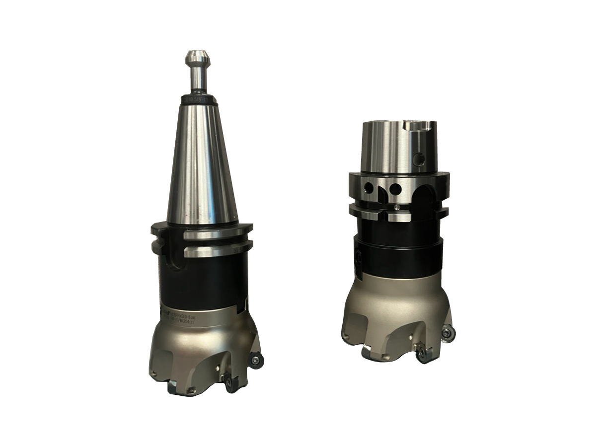
When replacing the platter on your UMC, the replacement platter will need to be re-machined to become square with the rest of the machine. The following tools and NC code are required to properly finish the platter replacement.

Required Tools Kit for Platter Replacement Based on Spindle Type Service kit number
UMC PLATTER CUTTING KIT CT40 EK-0034
UMC PLATTER CUTTING KIT BT40 EK-0035
UMC PLATTER CUTTING KIT HSK63A EK-0036
UMC PLATTER CUTTING KIT CT50 EK-0037
UMC PLATTER CUTTING KIT BT50 EK-0038
UMC Size Machine NC 
500 O00500.NC
750 O00750.NC
1000 O01000.NC
1250 O01250.NC

Platter Removal

1

Home the B and C-Axis.

Press [MDI], program "M13", press cycle start.

Press the Emergency Stop button.

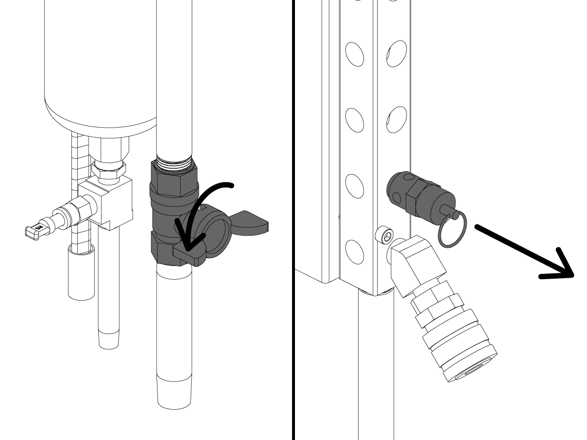
Open the lube panel on the tool-changer side of the machine. The wings of the valve should be parallel to the pipe. Rotate the ball valve shown to cut off air to the machine.

Purge excess air pressure from the machine by pulling and holding the ring on the purge valve until you no longer hear air escaping.

 Note: The initial pull of the ring will make a popping sound. This is normal

 Note: If you followed a link from the UMC C-AXIS BRAKE REPLACEMENT procedure to reach this page, complete this step then, skip to the Platter Installation section below.

2

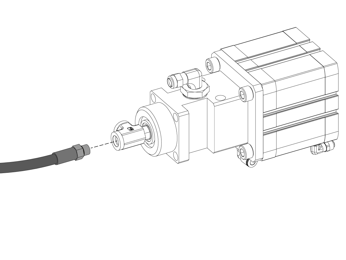
Remove the brake line from the C-Axis booster.

3

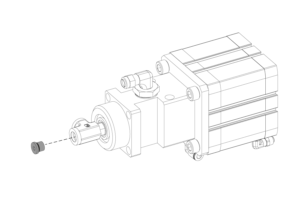
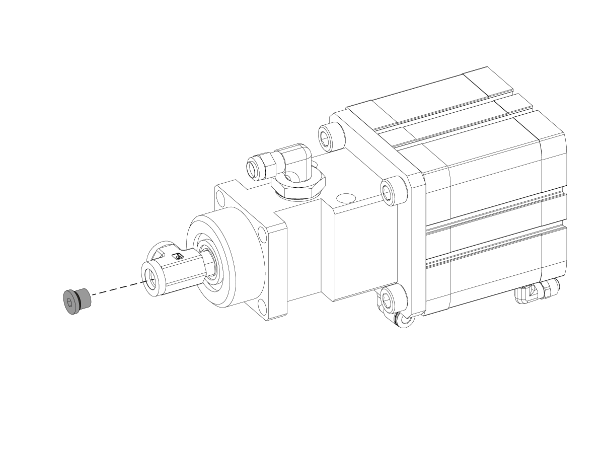
Install a Male 7/16"-20 O-Ring Boss fitting (dash number -04) into the booster where the brake line was removed. 

4

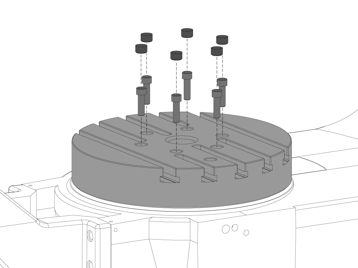
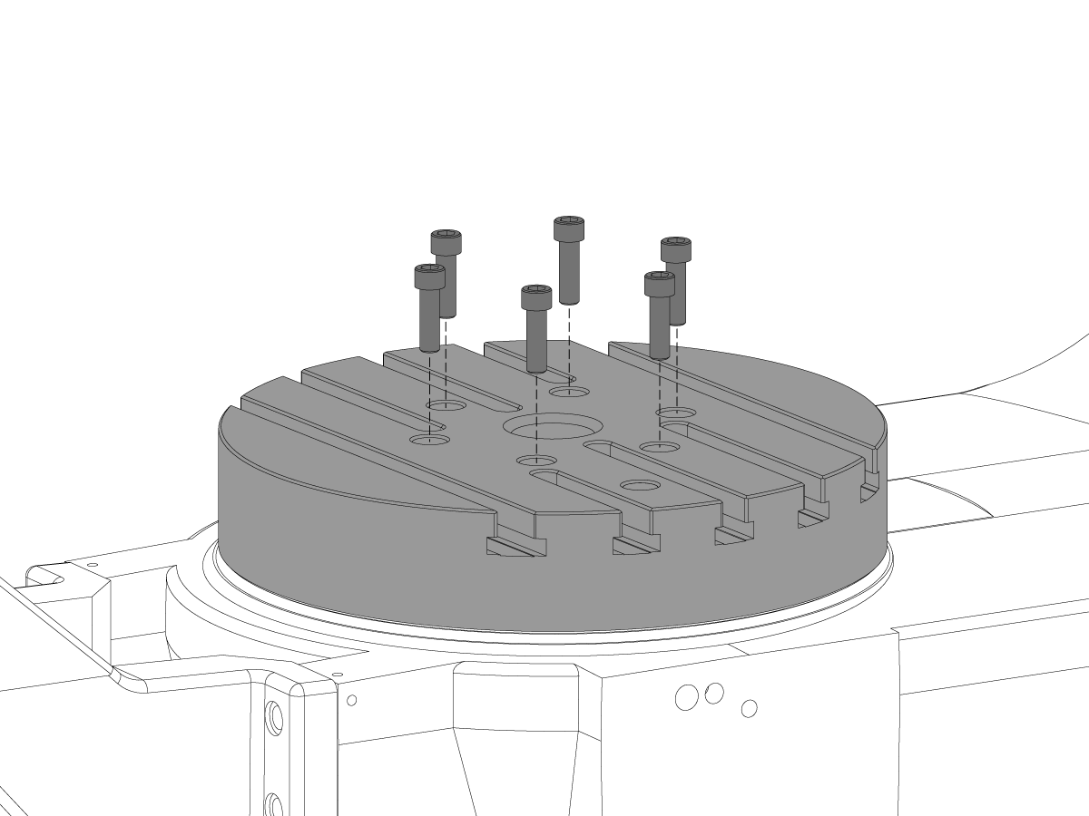
Remove the plastic bolt cover plugs to access the platter mounting bolts.

To do so drill a pilot hole then, insert a wood screw or similar to use as a handle to remove the plug. These will need to be replaced at the end of this procedure.

Next, remove the platter mounting bolts.

UMC Rotary Unit – Weight Reference Guide

5

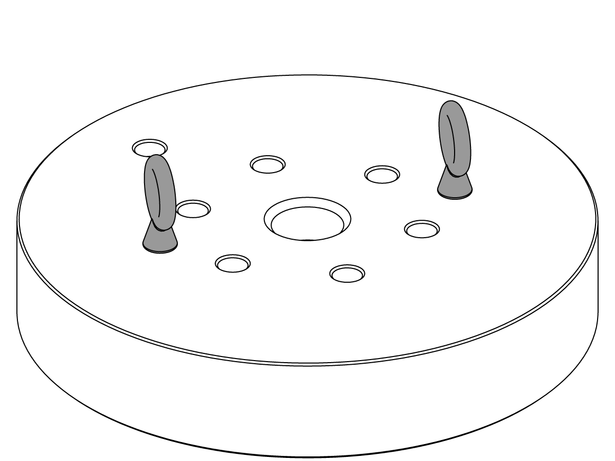
The platter can now be safely lifted from the rotary assembly. To do so first install 2 T-nuts and 2 eyebolts in the configuration shown. Next, use a lifting strap and crane/fork-lift to slowly lift the platter straight up and off of the rotary assembly. 

6

If removing a No-Slot or Pallet-Pool platter, you will need to use two (2) eyebolts as shown. Next, use a lifting strap and crane/fork-lift to slowly lift the platter straight up and off of the rotary assembly.


Platter Installation

1

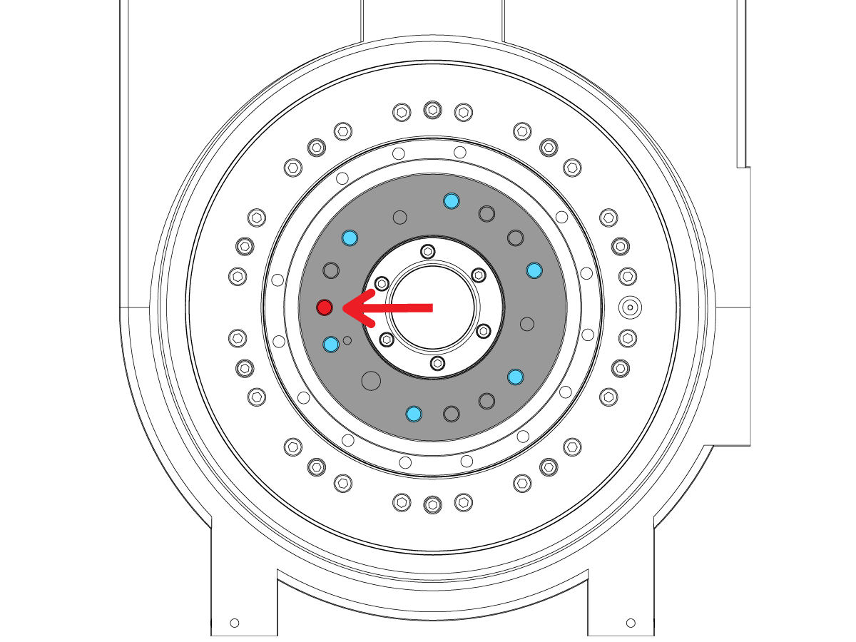
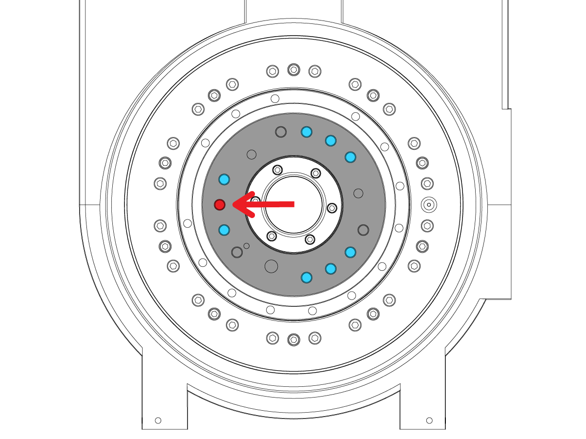
If installing a UMC 500 platter, be sure the gearbox mounting hole pattern is oriented as shown. The holes highlighted in blue show the bolt pattern position required to mount the platter. 

Note: The single hole highlighted in red needs to be pointing to the 9 O'clock position.

If the gear box is not in the orientation shown, you will need to jog the C-Axis to the correct position. To jog the C-Axis you will need to return air to the machine, release Emergency Stop, and clear alarms.

Warning: Before jogging the C-Axis verify the C-Axis booster is still plugged (see step 3 of the Removal Process above)

2

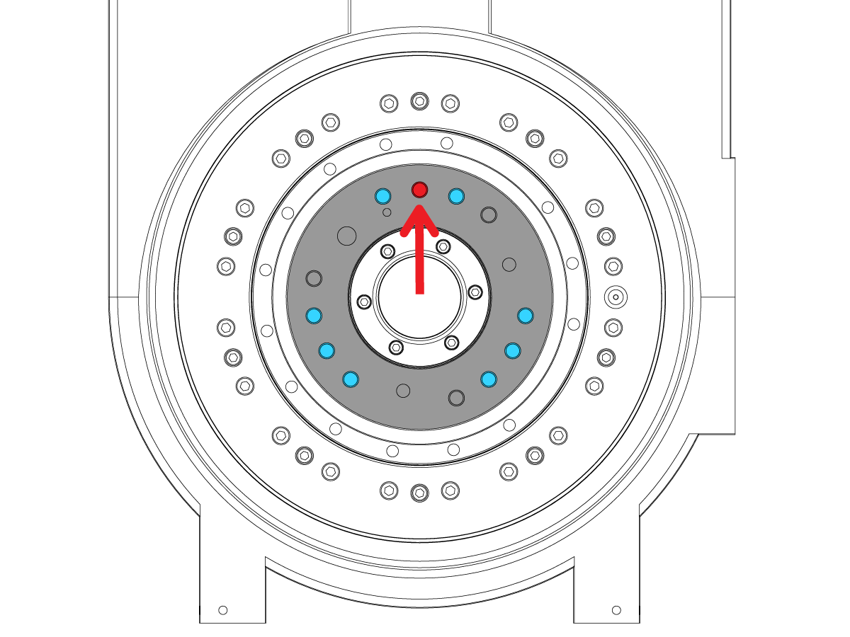
If installing a UMC-750, 1000 or 1250 platter, be sure the gearbox mounting hole pattern is oriented as shown. The holes highlighted in blue show the bolt pattern position required to mount the platter.  

Note: The single hole highlighted in red needs to be pointing to the 12 O'clock position. To jog the C-Axis you will need to return air to the machine, release Emergency Stop, and clear alarms.

If the gear box is not in the orientation shown, you will need to jog the C-Axis to the correct position.

Warning: Before jogging the C-Axis you will need to verify the C-Axis booster is still plugged (see step 3 of the Removal Process above)

3

If installing a Pallet Pool platter, be sure the gearbox mounting hole pattern is oriented as shown. The holes highlighted in blue show the bolt pattern position required to mount the platter.  

Note: The single hole highlighted in red needs to be pointing to the 9 O'clock position. To jog the C-Axis you will need to return air to the machine, release Emergency Stop, and clear alarms.

If the gear box is not in the orientation shown, you will need to jog the C-Axis to the correct position.

Warning: Before jogging the C-Axis you will need to verify the C-Axis booster is still plugged (see step 3 of the Removal Process above)

4

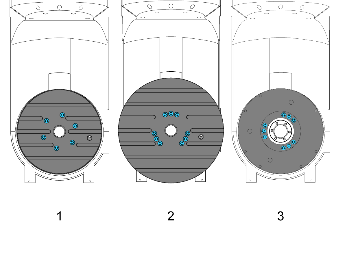
Next lower the platter onto the rotary assembly using one of the lifting configurations shown in Steps 5 & 6 of the Platter Removal section (above).

If installing a UMC-500 platter, place the platter onto the rotary assembly in the orientation shown on the left [1].

If installing a UMC-750/1000/1250 platter, place the platter onto the rotary assembly in the orientation shown in the middle [2].

If installing a UMC Pallet Pool platter, place the platter onto the rotary assembly in the orientation shown on the right [3].

5

Lightly install the platter mounting bolts. Do not torque in place. The platter position will need to be adjusted in the following steps.

6

If you did not need to jog the C-Axis in steps 1-3, ignore this step. Go to next step.

Press [MDI], program "M13", press cycle start.

Press the Emergency Stop button.

Open the lube panel on the tool-changer side of the machine. The wings of the valve should be parallel to the pipe. Rotate the ball valve shown to cut off air the the machine.

Purge excess air pressure from the machine by pulling and holding the ring on the purge valve until you no longer hear air escaping.

 Note: The initial pull of the ring will make a popping sound. This is normal

7

Remove the male ORB fitting from the booster.

8

Reinstall the brake line to the C-Axis booster.

9

Open the lube panel on the tool-changer side of the machine.

Rotate the ball valve shown to return air to the machine.


You will now need complete the C-Axis Bleeding portion of the UMC ROTARY BRAKE BLEEDING PROCEDURE before continuing to the next section.

Platter Alignment

1

Warning:  Do not perform any steps in this section without reading all steps in all previous sections.

Jog the platter while indicating off of the center bore ID. Runout must be 0.001" or less.  Adjust as needed. 

TORQUE THE PLATTER MOUNTING BOLTS TO SPEC then, verify runout.


2

SET C - AXIS TOOL CHANGE OFFSET AND MAKE PLATTER PARALLEL TO X

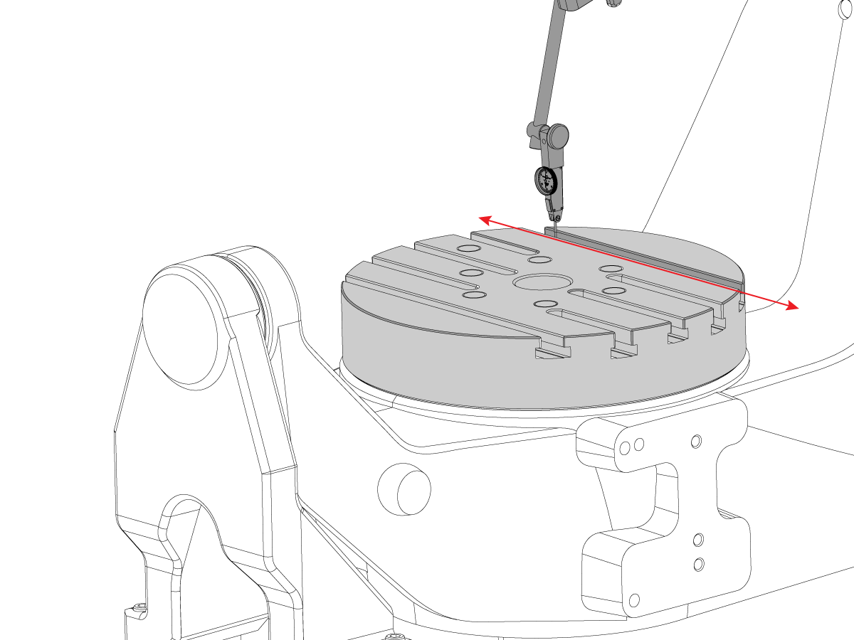
Check the Table Parallel to X-Axis by running an indicator on  the T-Slot. Adjust C axis to set Table parallel to X. (NTE 0.0005/10"; NTE 0.0010" overall).

In Service mode :  Go to the Parameters > Factory Settings page.

Type in .078 press [F1]

Enter the axis letter and press [F2] to set the tool change offset.

Platter Machining

1

Press [OFFSET] and go to the Work offsets page.

Set the X and Y-axis values for G54 based on the center bore of your platter. This can be done using either a dial indicator on the spindle or using your WIPS.

Set the Z, B, and C-axis to zero.


2

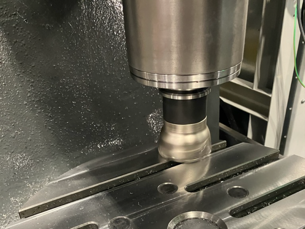
Put the shell mill listed above into Tool 1 in the machine. Set the tool length geometry offset for the shell mill using a tool setter or by using your WIPS.

Refer to Tool Offsets and Manual Tool Setters - Haas Tip of the Day 

3

Updated

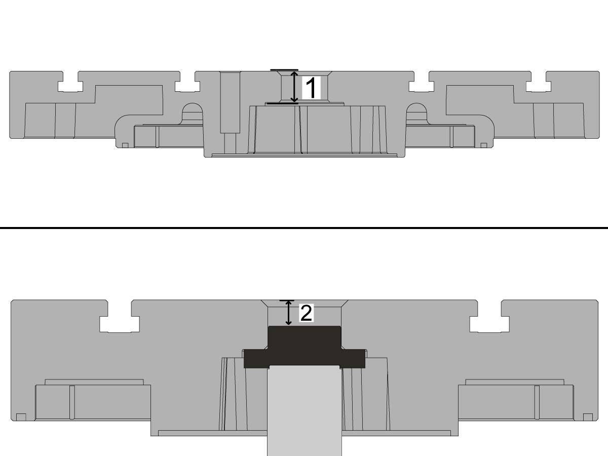
Using a 1-2" micrometer, measure the distance from the top of the platter to the bottom counter bore. The goal is to machine the platter to a height of 1.3250 ± .0010" [1]

For platters with work-holding, use a depth micrometer to measure the distance from the top of the platter to the union. The goal is to machine the platter to a height of 0.7000 ± .0010" for machines built before 5/22/2026 and 0.7560 ± .0010" for machines built after 5/22/2026. 

Note: For work-holding platters, the measurement is taken without the seal.

4

Press [SETTING] and search “245".

Turn Setting 245: Hazardous Vibration Safety to OFF.

Load the program into the control from your USB. Make sure to upload the code for the correct machine.

Note: Run the program in graphics mode to make sure no alarms or errors occur. If an over-travel alarm is produced, verify that G54 is set correctly in the center of the platter. If the alarm is still produced, then adjust the G-code to be 0.02 inches less than the positive most limit of the machine in G54.

5

Once all the above has been checked, run the program using 5% rapid on the first run through and 0.0000" in the Tool Length Wear register on the tool offsets page.

Once proofed through once with no issues, the rapid speed can be brought up to your comfort level.

Use the Tool Length Wear register to adjust the depth at which the machine will cut. Each pass should be in -0.003” or smaller increments. Rerun the program once you have updated the wear register.

Note: We recommend using some paint-pen or some dykem on the platter to confirm the tool is cutting the entire platter and not missing any spots.  

Note: The machine may not cut on the first run through.

6

Updated

Repeat until you measure the platter to be within the 1.3250 ± 0.0010” for standard platters or 0.7000 ± 0.0010”/0.7560 ± 0.0010” for work-holding platters from step 3.

After Machining Geometry Checks

1

Measure the platter face runout.

Note: C-Axis brake is off for this step.

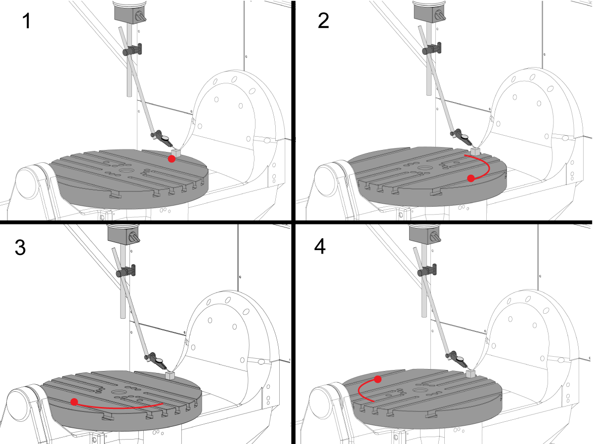
Place precision gauge block at the edge of the platter in the 12 o'clock position. Zero the indicator tip on the gauge block in this position. Rotate the C-axis  90° but, keep the gauge block at the 12 o'clock position. Take a measurement from the top of the gauge block

Repeat this 2 more times for a total of 4 positions, 90° apart, at the edge of the platter as shown. 

The total indicated runout. (NTE 0.001") 

2

Parallelism of Platter Surface to XY plane

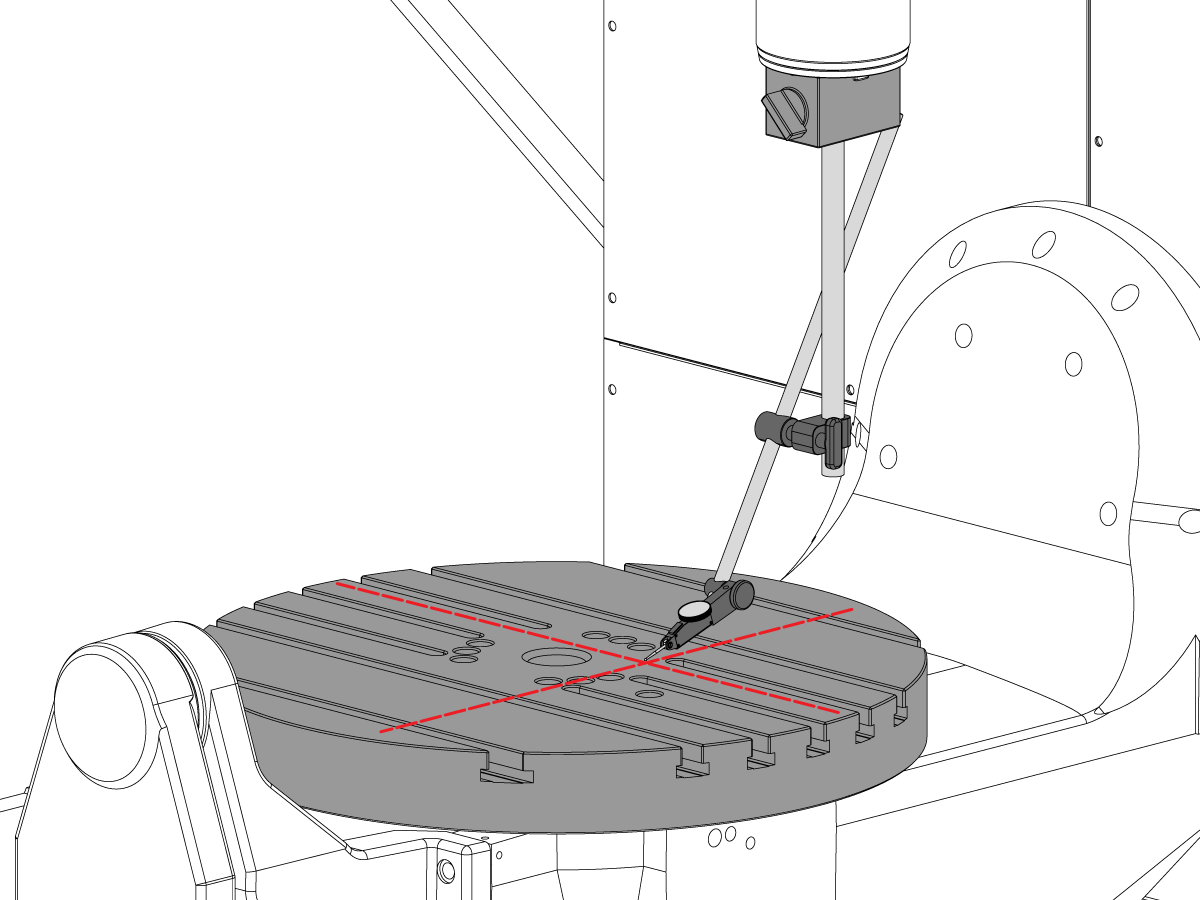
Zero-Return the C-axis so the T-slots run parallel to the X-axis

Place indicator tip on the platter and jog in the X-axis along the platter to find the X-axis platter parallelism (NTE 0.001” / 10"; 0.0015" / 15")

Next jog in the Y-axis along the platter to find the Y-axis platter parallelism (NTE 0.001” / 10"; 0.0015" / 15")

Recently Viewed Items

You Have No Recently Viewed Items Yet

Feedback
Haas Logo

Haas Delivered Price

This price includes shipping cost, export and import duties, insurance, and any other expenses incurred during shipping to a location in France agreed with you as a buyer. No other mandatory costs can be added to the delivery of a Haas CNC Product.

KEEP UP WITH THE LATEST HAAS TIPS AND TECHNOLOGY...

Sign up now!   

HAAS TOOLING ACCEPTS THE FOLLOWING:

  • Service & Support
  • Owners
  • Request Service
  • Operator Manuals
  • Haas Parts
  • Rotary Repair Request
  • Pre-Install Guides
  • Shopping Tools
  • Build & Price a New Haas
  • Available Inventory
  • The Haas Price List
  • CNCA Financing
  • About Haas
  • Accessibility Statement
  • DNSH Statement
  • Export Compliance
  • Careers
  • Certifications & Safety
  • Contact Us
  • History
  • Terms & Conditions
  • Haas Tooling Terms & Conditions
  • Privacy
  • Warranty
  • Haas Community
  • Haas Certification Program
  • Haas Motorsports
  • Gene Haas Foundation
  • Haas Technical Education Community
  • Events
  • Join the Conversation
  • Facebook
  • X
  • Flickr
  • YouTube
  • LinkedIn
  • Instagram
  • TikTok
© 2026 Haas Automation, Inc – CNC Machine Tools
This site is protected by reCAPTCHA and the Google Privacy Policy and Terms of Service apply.

2800 Sturgis Rd., Oxnard, CA 93030
Toll Free: (888) 817-4446 / Fax: 805-278-8554