-
machines
Main Menu
-
Vertical Mills
Vertical MillsVertical Mills View All
- Vertical Mills
- VF Series
- Universal Machines
- VR Series
- VP-5 Prismatic
- Pallet-Changing VMCs
- Mini Mills
- Mold Machines
- High-Speed Drill Centers
- Drill/Tap/ Mill Series
- Toolroom Mills
- Compact Mills
- Gantry Series
- SR Sheet Routers
- Extra-Large VMC
- Double-Column Mills
- Pocket Mill
- Mill Automatic Parts Loader
- VMC/UMC Side-Loading Automatic Parts Loader
- Compact Automatic Parts Loader
-
Multi-Axis Solutions
Multi-Axis SolutionsMulti-Axis Solutions View All
-
Lathes
LathesLathes View All
-
Horizontal Mills
Horizontal MillsHorizontal Mills View All
-
Rotaries & Indexers
Rotaries & IndexersRotaries & Indexers View All
-
Special Series
Special SeriesSpecial Series View All
-
Automation Systems
Automation SystemsAutomation Systems View All
-
Desktop Machines
Desktop MachinesDesktop Machines View All
-
Shop Equipment
Shop EquipmentShop Equipment View All
-
Pocket Machines
Pocket MachinesPocket Machines View All
QUICK LINKS Special Series Special SeriesSHOPPING TOOLSWANT TO TALK TO SOMEONE?A Haas Factory Outlet (HFO) can answer your questions, and walk you through your best options.
CONTACT YOUR DISTRIBUTOR > -
Vertical Mills
-
Options
Main Menu
-
/VOP-new-way-to-save.gif) Value Option Packages
Value Option PackagesValue Option Packages View All
Value Option Packages
Value Option PackagesValue Option Packages View All -
 Spindles
Spindles View All
Spindles
SpindlesSpindles View All -
 Tool Changers
Tool Changers View All
Tool Changers
Tool ChangersTool Changers View All -
 4th- | 5th-Axis
4th- | 5th-Axis View All
4th- | 5th-Axis
4th- | 5th-Axis4th- | 5th-Axis View All -
 Turrets & Live Tooling
Turrets & Live Tooling View All
Turrets & Live Tooling
Turrets & Live ToolingTurrets & Live Tooling View All -
 Probing
Probing View All
Probing
ProbingProbing View All -
 Chip & Coolant Management
Chip & Coolant Management View All
Chip & Coolant Management
Chip & Coolant ManagementChip & Coolant Management View All -
 The Haas Control
The Haas Control View All
The Haas Control
The Haas ControlThe Haas Control View All -
 Product Options
Product Options View All
Product Options
Product OptionsProduct Options View All -
 Tooling & Fixturing
Tooling & Fixturing View All
Tooling & Fixturing
Tooling & FixturingTooling & Fixturing View All -
 Workholding
Workholding View All
Workholding
WorkholdingWorkholding View All -
 5-Axis Solutions
5-Axis Solutions View All
5-Axis Solutions
5-Axis Solutions5-Axis Solutions View All -
VF-Super-Speed - Super Features Come Standard! | Haas CNC
VF-Super-Speed - Super Features Come Standard! | Haas CNCVF-Super-Speed - Super Features Come Standard! | Haas CNC View All -
UMC-Super-Speed - Super Features Come Standard! | Haas CNC
UMC-Super-Speed - Super Features Come Standard! | Haas CNCUMC-Super-Speed - Super Features Come Standard! | Haas CNC View All -
ST-Y-Axis Standard Features | Haas CNC
ST-Y-Axis Standard Features | Haas CNCST-Y-Axis Standard Features | Haas CNC View All
QUICK LINKS Special Series Special SeriesSHOPPING TOOLSWANT TO TALK TO SOMEONE?A Haas Factory Outlet (HFO) can answer your questions, and walk you through your best options.
CONTACT YOUR DISTRIBUTOR > -
-
Why Haas
Main Menu
Discover the Haas Difference
-
Service
Main Menu
Welcome to Haas Service
- Videos Main Menu
-
Main Menu
QUICK LINKS Special Series Special SeriesSHOPPING TOOLSWANT TO TALK TO SOMEONE?
A Haas Factory Outlet (HFO) can answer your questions, and walk you through your best options.
CONTACT YOUR DISTRIBUTOR > -
Haas Tooling
Main Menu
- Haas Tooling
-
Winner's CircleWinner's Circle Shop All
-
Winner's CircleWinner's Circle Shop All
-
Today’s Hot DealsToday’s Hot Deals Shop All
-
ClearanceClearance Shop All
-
Measuring & InspectionMeasuring & Inspection Shop All
- Probe Kits & Accessories
- Edge & Center Finders
- Comparative Measuring Gauges
- Height Gauges
- Calipers
- Threaded Plug & Ring Gauges
- Gauge Blocks
- Pin Gauges
- Drop Indicators
- Dial Test Indicators
- Bore Gauges
- Indicator Accessories
- V Blocks
- Setup Blocks
- Depth Measuring
- Micrometers
- Micrometer Accessories
- Micrometer Kits
- Bore Gauge Kits
- Starter Kits
- Indicator Kits
- Caliper Kits
- Toolholder Check Station
- Height Setters
- Coordinate Measuring Machines
-
Automation AccessoriesAutomation Accessories Shop All
-
Shop SupportShop Support Shop All
-
Mill ToolholdingMill Toolholding Shop All
-
Mill ToolingMill Tooling Shop All
- Shell Mill Bodies
- Milling Inserts
- End Mills
- Chamfer Mills & Inserts
- Indexable End Mill Bodies
- Ball End Mills
- Chamfer End Mills
- Roughing End Mills
- Indexable Ball End Mills & Inserts
- Shell Mill Kits
- Chamfer Mill Kits
- Indexable End Mill Kits
- Dovetail Cutters
- Indexable Dovetail Cutters
- Engraving End Mills
- Rotary Burrs / Die Grinding Bits
- Keyseat Cutters
- Corner Rounding End Mills
- Slot Mill Bodies
- CNC Router Bits For Wood
- Indexable CNC Router Bits & Inserts
-
Boring SystemsBoring Systems Shop All
-
Mill WorkholdingMill Workholding Shop All
-
Lathe ToolholdingLathe Toolholding Shop All
-
Lathe ToolingLathe Tooling Shop All
- Cut-Off Tool Blocks & Blades
- Cut-Off Tooling Kits
- Turning Inserts
- Grooving & Cut-Off Tools
- Internal (ID) Grooving & Threading Tools
- Threading Inserts
- Threading Tools
- Boring Bars / Internal (ID) Turning Tools
- External (OD) Turning Tools
- Cermet Turning Inserts
- CBN Turning Inserts
- Haas Notch Grooving & Threading Inserts
- Haas Notch Grooving & Threading Tools
- Micro Turning Tools
- Desktop Lathe Tools
- Indexable Antivibration Boring Bars
-
Lathe WorkholdingLathe Workholding Shop All
-
Package KitsPackage Kits Shop All
- Chip Clearing Fan Kits
- Cutting Tool Kits
- Indexable End Mill Kits
- Cut-Off Tool Block & Blade Kits
- Drill & Tap Kits
- Indexable Drilling Kits
- Shell Mill Kits
- Chamfer Mill Kits
- Rotary Tool Holder & Tool Chuck Kits
- Lathe Starter Kits
- Workholding Kits
- Rotary Vise Kits
- Vise Kits
- 3-Jaw Chuck Kits for Mills
- Tombstone Kits
- Reduction Sleeve Kits
- Automated Workholding Kits
- 08-1869
- 08-1870
- Measuring & Inspection Kits
- Starter Kits
- Bore Gauge Kits
- Caliper Kits
- Indicator Kits
- Micrometer Kits
-
ER Collets & ChucksER Collets & Chucks Shop All
-
HolemakingHolemaking Shop All
-
ThreadingThreading Shop All
-
BroachingBroaching Shop All
-
TombstonesTombstones Shop All
-
Manual Chucks For MillingManual Chucks For Milling Shop All
-
Deburring & AbrasivesDeburring & Abrasives Shop All
-
Tool Presetter & Heat ShrinkersTool Presetter & Heat Shrinkers Shop All
-
Tool StorageTool Storage Shop All
-
Machine MaintenanceMachine Maintenance Shop All
-
Tooling AccessoriesTooling Accessories Shop All
-
Apparel & AccessoriesApparel & Accessories Shop All
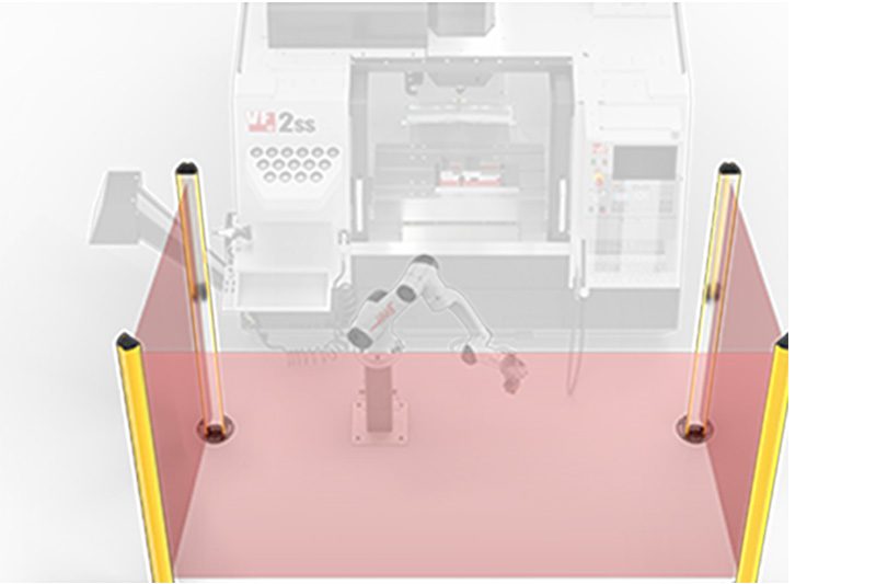 Automation Accessories
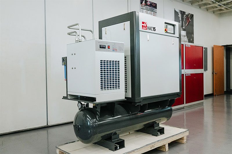 Shop Support
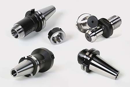 Mill Toolholding
 Mill Cutting Tools
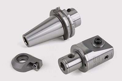 Boring Systems
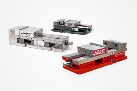 Mill Workholding
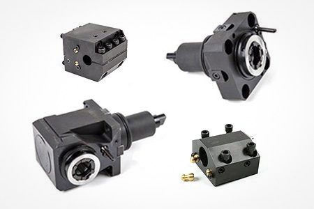 Lathe Toolholding
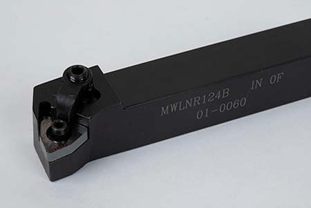 Lathe Cutting Tools
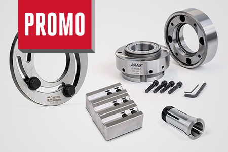 Lathe Workholding
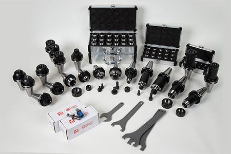 Package Kits
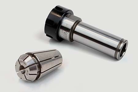 ER Collets & Chucks
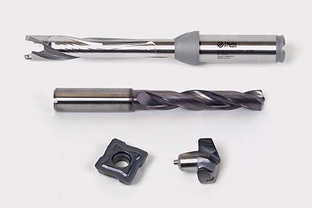 Holemaking
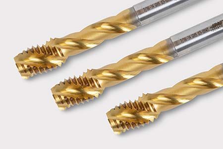 Threading
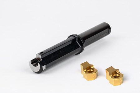 Broaching
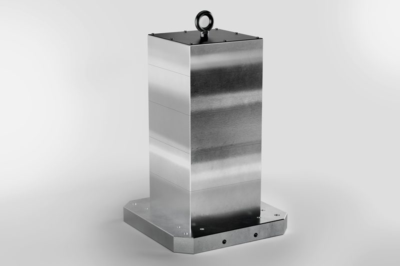 Tombstones & Kits
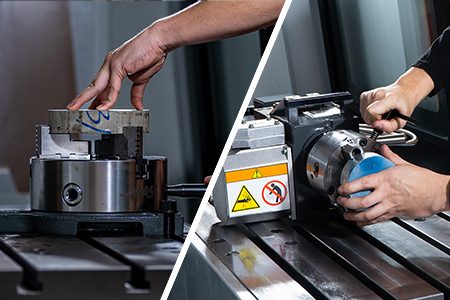 Manual Chucks For Milling
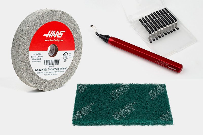 Deburring & Abrasives
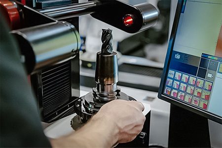 Tool Presetter & Heat Shrinkers
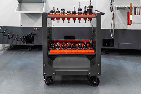 Storage & Handling
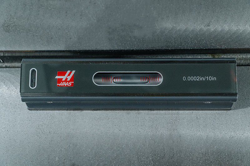 Machine Maintenance
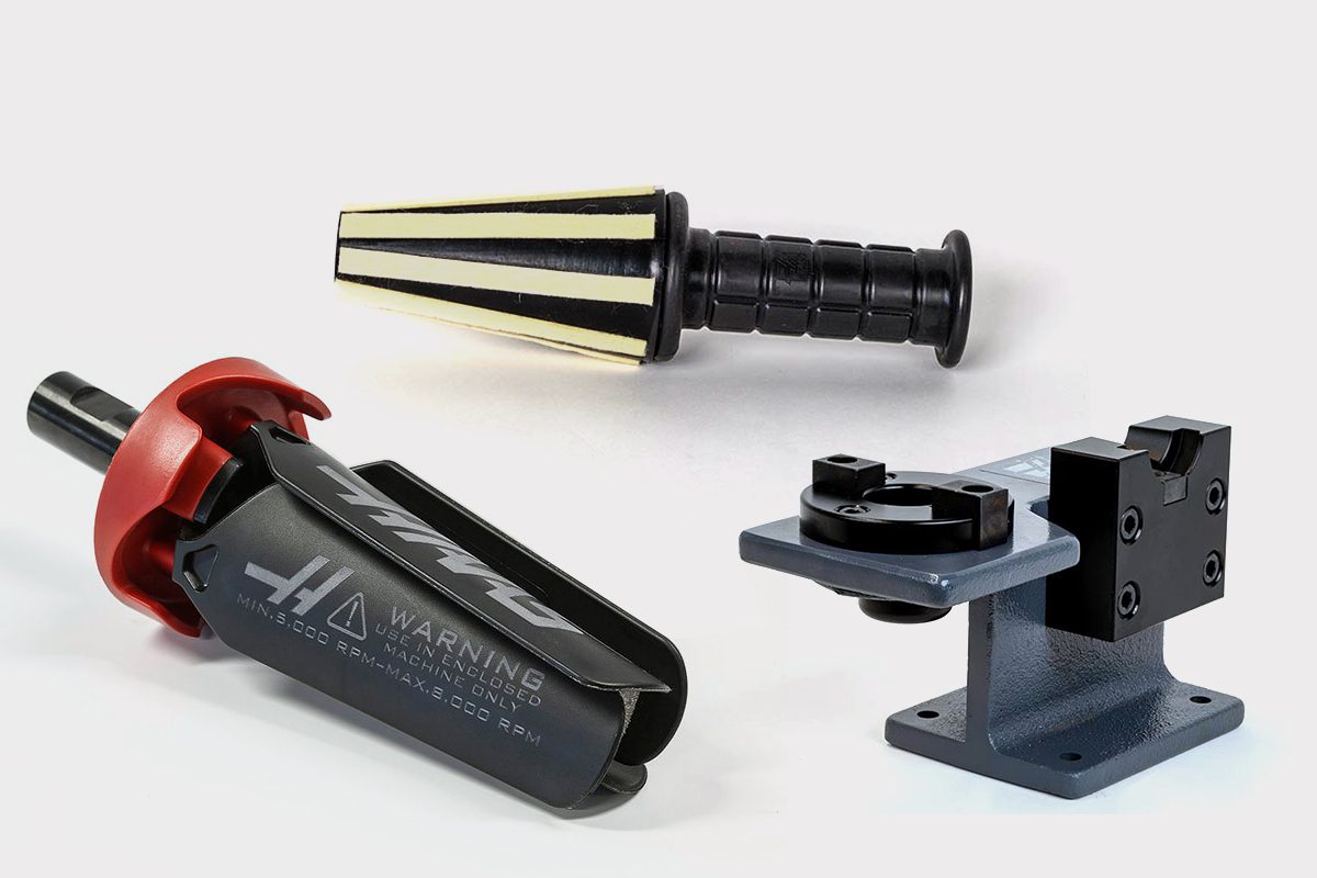 Tooling Accessories
 Apparel & Accessories
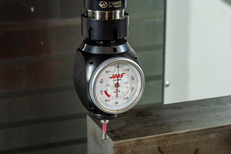 Measuring & Inspection
 Winner's Circle
 Winner's Circle
 Clearance
 Today's Hot Deals
-
Haas Service Parts
Main Menu
- Haas Service Parts
-
Automatic Pallet ChangerAutomatic Pallet Changer Shop All
-
Lathe TurretLathe Turret Shop All
-
Tool ChangerTool Changer Shop All
-
Chip ManagementChip Management Shop All
-
CoolantCoolant Shop All
-
CounterbalanceCounterbalance Shop All
-
Electrical CabinetElectrical Cabinet Shop All
-
EnclosureEnclosure Shop All
-
HydraulicsHydraulics Shop All
-
LubricationLubrication Shop All
-
MaintenanceMaintenance Shop All
-
PendantPendant Shop All
-
ProbingProbing Shop All
-
RotaryRotary Shop All
-
SpindlesSpindles Shop All
-
TailstockTailstock Shop All
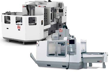 Automatic Pallet Changer
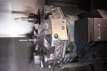 Lathe Turret
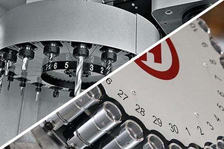 Tool Changer
 Chip Management
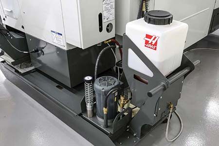 Coolant
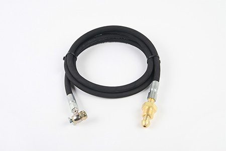 Counterbalance
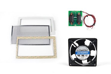 Electrical Cabinet
 Enclosure
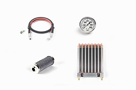 Hydraulics
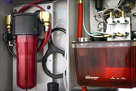 Lubrication
 Maintenance
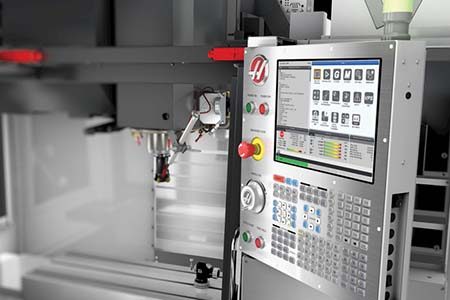 Pendant
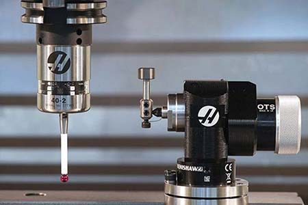 Probing
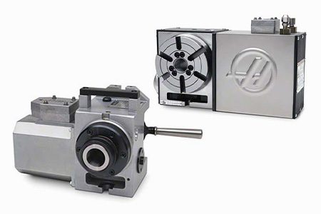 Rotary
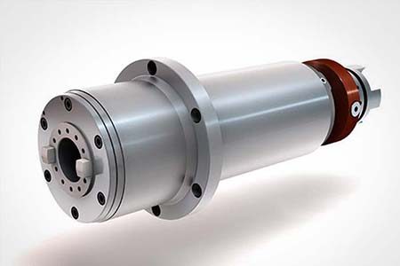 Spindle
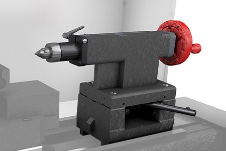 Tailstock


