My Haas Welcome,
!
Haas Tooling MyHaas/HaasConnect Sign In Register Haas Tooling MyHaas/HaasConnect Sign Out Welcome, My Machines Latest Activity My Quotes My Account My Users Sign Out
Find Your Distributor
  1. Select Language
    1. English
    2. Deutsch
    3. Español - ES
    4. Español - MX
    5. Français
    6. Italiano
    7. Português
    8. Český
    9. Dansk
    10. Nederlands
    11. Magyar
    12. Polski
    13. Svenska
    14. Türkçe
    15. 中文
    16. Suomi
    17. Norsk
    18. الإنجليزية
    19. български
    20. Hrvatski
    21. Ελληνικά
    22. Română
    23. Slovenský
    24. Slovenščina
    25. 한국어
    26. 日本語
    27. Українська
  • machines Main Menu
    • Vertical Mills
      Vertical Mills
      Vertical Mills View All
      • Vertical Mills
      • VF Series
      • Universal Machines
      • VR Series
      • VP-5 Prismatic
      • Pallet-Changing VMCs
      • Mini Mills
      • Mold Machines
      • High-Speed Drill Centers
      • Drill/Tap/ Mill Series
      • Toolroom Mills
      • Pocket Mill
      • Compact Mills
      • Gantry Series
      • SR Sheet Routers
      • Extra-Large VMC
      • Double-Column Mills
      • 3+2 Positioning Machines
    • Multi-Axis Solutions
      Multi-Axis Solutions
      Multi-Axis Solutions View All
      • Multi-Axis Solutions
      • Y-Axis Lathes
      • 5-Axis Mills
    • Lathes
      Lathes
      Lathes View All
      • Lathes
      • ST Series
      • Dual-Spindle
      • Box Way Series
      • Toolroom Lathes
      • Chucker Lathe
      • Pocket Lathe
      • Haas Bar Feeders
    • Horizontal Mills
      Horizontal Mills
      Horizontal Mills View All
      • Horizontal Mills
      • 50-Taper
      • 40-Taper
    • Rotaries & Indexers
      Rotaries & Indexers
      Rotaries & Indexers View All
      • Rotaries & Indexers
      • Rotary Tables
      • Indexers
      • 5-Axis Rotaries
      • Extra-Large Rotaries
    • Special Series
      Special Series
      Special Series View All
      • Special Series
      • EU_Series_Redirect
    • Automation Systems
      Automation Systems
      Automation Systems View All
      • Automation Systems
      • Mill Automation
      • Lathe Automation
      • Automatic Parts Loaders
      • Automation Models
    • Desktop Machines
      Desktop Machines
      Desktop Machines View All
      • Desktop Machines
      • Desktop Mill
      • Desktop Lathe
      • Control Simulator, Standard
      • Control Simulator, Premium
    • Shop Equipment
      Shop Equipment
      Shop Equipment View All
      • Shop Equipment
      • Knee Mill
      • Haas Manual Lathes
      • Haas Saws
    • Fabrication Machines
      Fabrication Machines
      Fabrication Machines View All
      • Fabrication Machines
      • Laser Cutting Machines
      • CNC Press Brakes
    • QUICK LINKS Special Series  Special Series 
      EU SERIES EU SERIES BUILD & PRICE | PRICE LIST BUILD & PRICE | PRICE LIST In-Stock Machines In-Stock Machines WHAT’S NEW WHAT’S NEW YOUR FIRST CNC YOUR FIRST CNC
      SHOPPING TOOLS
      • Build & Price a Haas
      • Price List
      • Available Inventory
      • CNCA Financing
      WANT TO TALK TO SOMEONE?

      A Haas Factory Outlet (HFO) can answer your questions, and walk you through your best options.

      CONTACT YOUR DISTRIBUTOR >
  • Options Main Menu
    • The Haas Control Value Option Packages
      Value Option Packages
      Value Option Packages View All
      • Value Option Packages
    • Product Image Spindles
      Spindles
      Spindles View All
      • Spindles
    • Product Image Tool Changers
      Tool Changers
      Tool Changers View All
      • Tool Changers
    • Product Image 4th- | 5th-Axis
      4th- | 5th-Axis
      4th- | 5th-Axis View All
      • 4th- | 5th-Axis
    • Product Image Turrets & Live Tooling
      Turrets & Live Tooling
      Turrets & Live Tooling View All
      • Turrets & Live Tooling
    • Product Image Probing
      Probing
      Probing View All
      • Probing
    • Haas Chip & Coolant Management Chip & Coolant Management
      Chip & Coolant Management
      Chip & Coolant Management View All
      • Chip & Coolant Management
    • The Haas Control The Haas Control
      The Haas Control
      The Haas Control View All
      • The Haas Control
    • Product Image Product Options
      Product Options
      Product Options View All
      • Product Options
    • Product Image Tooling & Fixturing
      Tooling & Fixturing
      Tooling & Fixturing View All
      • Tooling & Fixturing
    • Product Image Workholding
      Workholding
      Workholding View All
      • Workholding
    • Product Image 5-Axis Solutions
      5-Axis Solutions
      5-Axis Solutions View All
      • 5-Axis Solutions
      • 5 Easy Steps to 5-Axis
    • QUICK LINKS Special Series  Special Series 
      EU SERIES EU SERIES BUILD & PRICE | PRICE LIST BUILD & PRICE | PRICE LIST In-Stock Machines In-Stock Machines WHAT’S NEW WHAT’S NEW YOUR FIRST CNC YOUR FIRST CNC
      SHOPPING TOOLS
      • Build & Price a Haas
      • Price List
      • Available Inventory
      • CNCA Financing
      WANT TO TALK TO SOMEONE?

      A Haas Factory Outlet (HFO) can answer your questions, and walk you through your best options.

      CONTACT YOUR DISTRIBUTOR >
  • Why Haas Main Menu
      Discover the Haas Difference
    • Why Haas
    • MyHaas
    • Education Community
    • Industry 4.0
    • Haas Certification
    • Customer Testimonials
  • Service Main Menu
      Welcome to Haas Service
      SERVICE HOME Operator’s Manuals How-To Procedures Troubleshooting Guides Preventive Maintenance Haas Parts Haas Tooling Videos
  • Videos Main Menu
  • Main Menu
    • View All
    • View All
    • View All
    • View All
      • HTEC Curriculum Support
      • Haas Value Option Packages (VOP) Journey
    • View All
      • Haas 10 kg Cobot Package
      • Cobot Kits
      • DC-1 Drill Center
      • CNC Sales News
      • Do More With Your Haas
    • View All
    • View All
      • contact-us-test
      • 4 - AUTOMATION SYSTEMS
      • Carousel-V2
      • expert test
      • Demo_Day_Trident-test
      • Link Test
      • image-sale-tag-test
      • article-list-test
      • Haas 25 kg Robot Package
      • test-algolia-page
    • View All
    • View All
    • View All
    • View All
      • calc-test
    • View All
    • QUICK LINKS Special Series  Special Series 
      EU SERIES EU SERIES BUILD & PRICE | PRICE LIST BUILD & PRICE | PRICE LIST In-Stock Machines In-Stock Machines WHAT’S NEW WHAT’S NEW YOUR FIRST CNC YOUR FIRST CNC
      SHOPPING TOOLS
      • Build & Price a Haas
      • Price List
      • Available Inventory
      • CNCA Financing
      WANT TO TALK TO SOMEONE?

      A Haas Factory Outlet (HFO) can answer your questions, and walk you through your best options.

      CONTACT YOUR DISTRIBUTOR >
  • Haas Tooling Main Menu
  • Haas Service Parts Main Menu

My Haas Welcome,
!
Haas Tooling MyHaas/HaasConnect Sign In Register Haas Tooling MyHaas/HaasConnect Sign Out Welcome, My Machines Latest Activity My Quotes My Account My Users Sign Out
Find Your Distributor
  1. Select Language
    1. English
    2. Deutsch
    3. Español - ES
    4. Español - MX
    5. Français
    6. Italiano
    7. Português
    8. Český
    9. Dansk
    10. Nederlands
    11. Magyar
    12. Polski
    13. Svenska
    14. Türkçe
    15. 中文
    16. Suomi
    17. Norsk
    18. الإنجليزية
    19. български
    20. Hrvatski
    21. Ελληνικά
    22. Română
    23. Slovenský
    24. Slovenščina
    25. 한국어
    26. 日本語
    27. Українська
×

Search Results

Web Pages

Images

    • <
    • 1
    • >

VF-5TR, VF-6TR - Integrated Trunnion Removal and Installation - AD0334

Service Home How To Procedures VF-5TR, VF-6TR - Integrated Trunnion - Removal and Installation - CHC
Recently Updated Last updated: 04/03/2023

VF-5TR, VF-6TR - Integrated Trunnion - Removal and Installation - CHC


AD0334

VF-5TR, VF-6TR - Integrated Trunnion - Removal and Installation - CHC

- Jump to Section - 1. Introduction 2. VF-5TR, VF-6TR - Integrated Trunnion - Removal (5 steps) 3. VF-5TR, VF-6TR - Integrated Trunnion - Installation (6 steps) 4. VF-5TR, VF-6TR - Integrated Trunnion - Replacement Grid Offset (2 steps) 5. VF-5TR, VF-6TR - Integrated Trunnion - Alignment (7 steps) Back to Top

Introduction

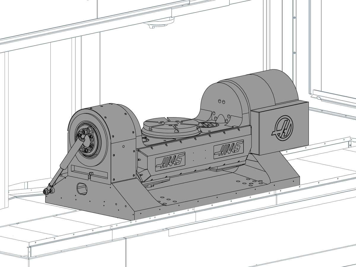
This procedure tells you how to remove and install an integrated trunnion assembly.

A temporary shipping base is sent from the factory. The damaged trunnion is attached to the base and returned to the factory. The repaired trunnion is shipped attached to the base. After the trunnion assembly is installed, the base is shipped back to the factory.

Required Materials

  • For VF-5TR: 93-2126 VF-6TR, TRUNNION SERVICE KIT. QTY: 1
  • For VF-6TR: 93-2127 VF-5TR, TRUNNION SERVICE KIT. QTY: 1
  • Lifting spreader bar
  • Dead blow hammer
  • Lifting system with 2500lb (1140 kg) Capacity
  • Eye Bolt: 49-1008 EYE BOLT 1/2-13 X 0.88 X 1.19 I.D. SHLDR. 

VF-5TR, VF-6TR - Integrated Trunnion - Removal

1

Zero return all axes. 

Push [EMERGENCY STOP].

Set Parameter 43:20, A axis CK TRAVL LTM-, to 0. 

Release [EMERGENCY STOP]

Jog the X axis until the table is under the spindle. 

Jog the A axis to 180 degrees. 

Push [EMERGENCY STOP]

2

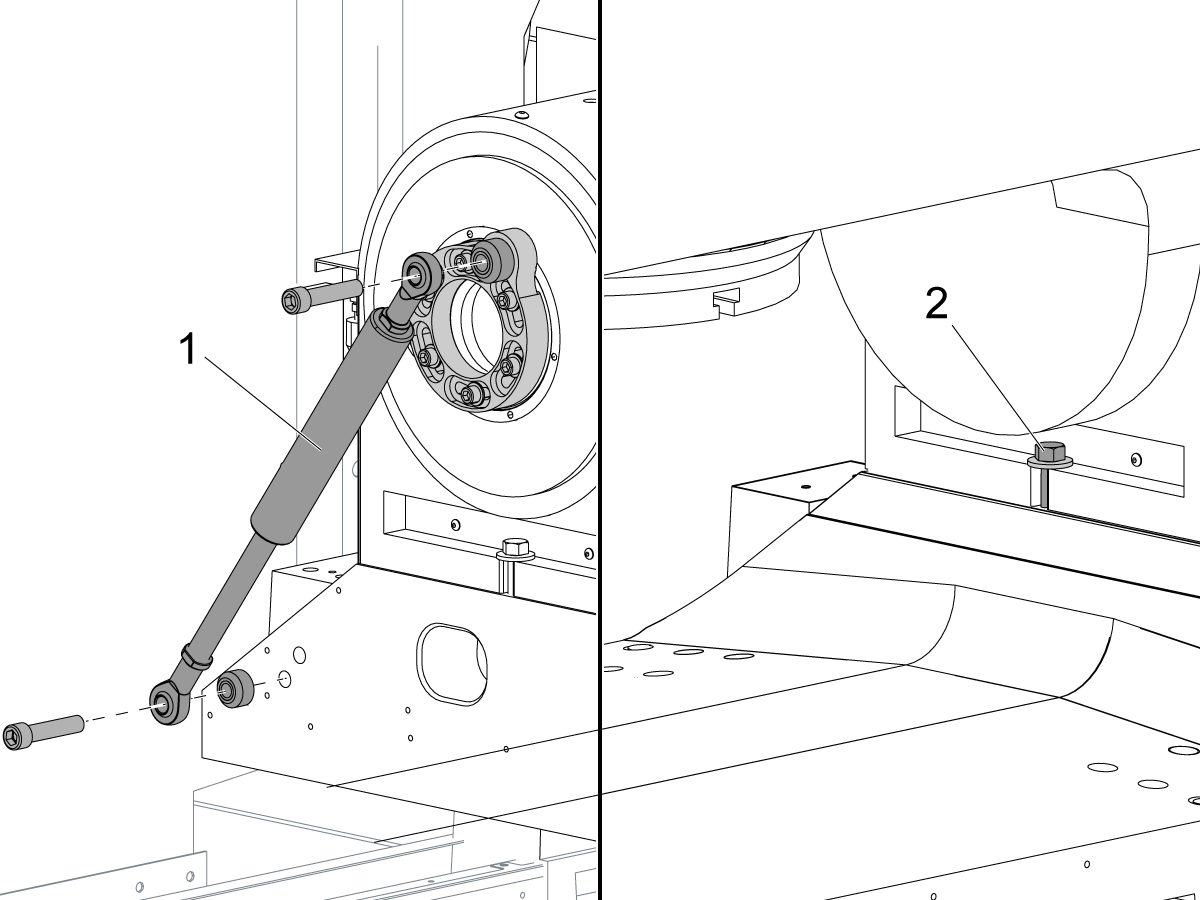
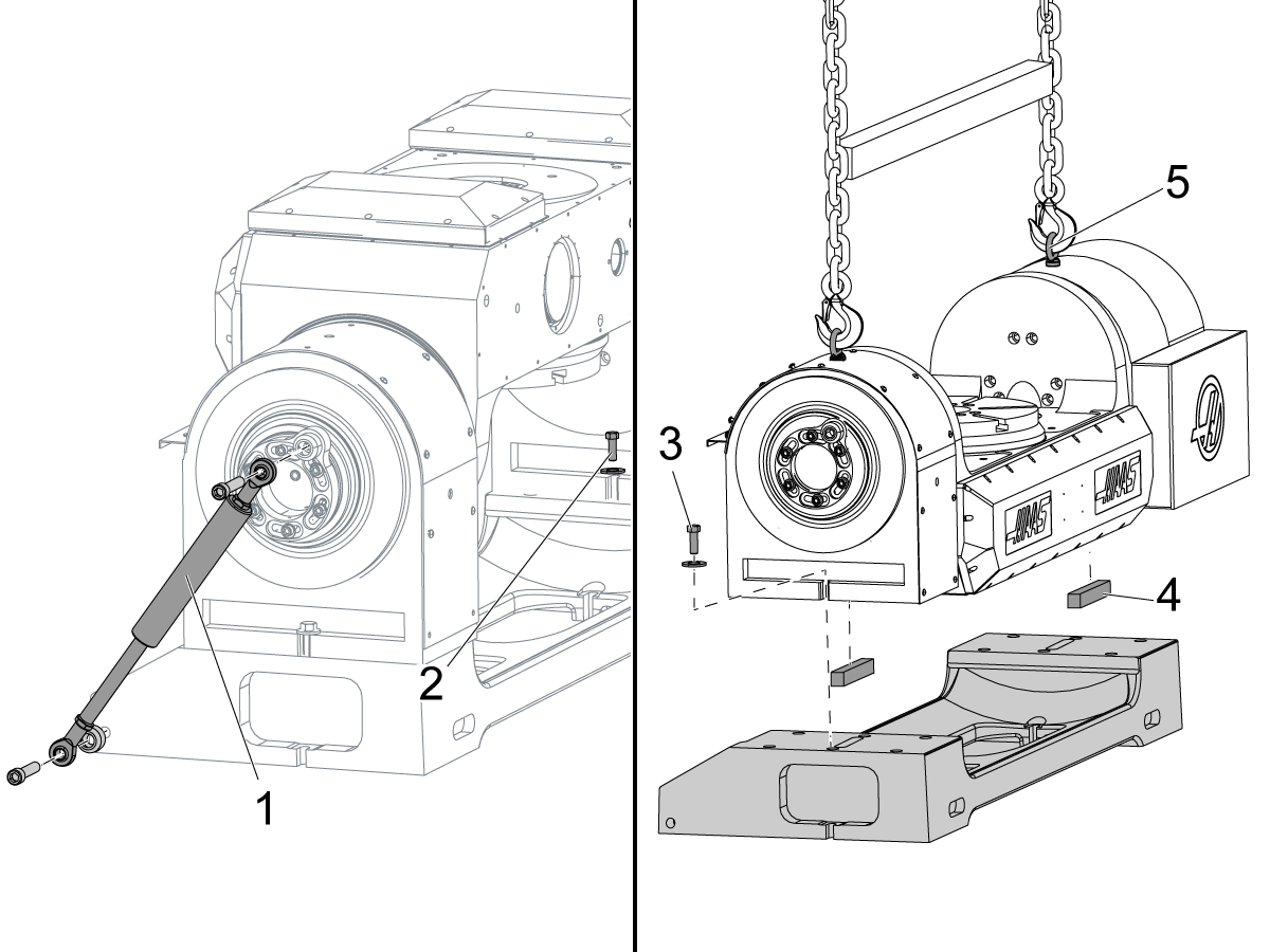
Remove the counterbalance cylinder [1].

Remove the (2) inboard hex screws [2] from the trunnion base.

Release the [EMERGENCY STOP].

Jog the A Axis to 0 degrees.

Push [POWER OFF].

Remove the (2) outboard hex screws from the trunnion base.

3

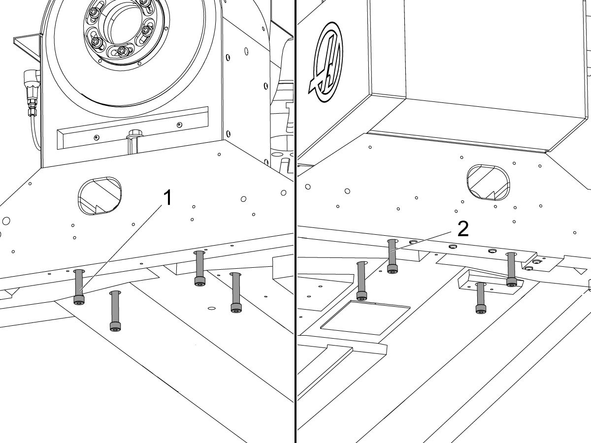
Remove the (4) socket-head cap screws from under the left-hand rotary [1] and from under the right-hand rotary [2], as shown.

Disconnect the A-Axis and B-Axis power and encoder cables.

 Warning: Do not disconnect the air supply to the trunnion.

4

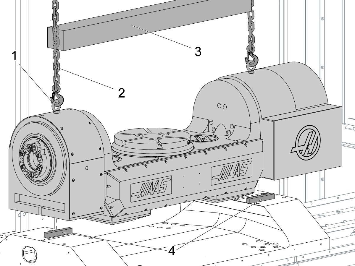
Install eye bolts [1] onto the top of the trunnion assembly.

Put the chains [2] from the lift through the eye bolts. Place a spreader bar [3] between the chains.

 Warning: Ensure the air supply is connected to the trunnion assembly. Do not move the trunnion assembly without air pressure.

 Warning: The trunnion assembly weighs over 2150 lb (975 kg). Make sure to use a lift of the correct capacity.

Lift the trunnion assembly clear of the receiver table.

Remove the permanent slide keys [4] that were installed with the trunnion from under the trunnion base.

Note: Do not lose the slide keys. You will need them to install the repaired trunnion assembly.

5

Install the temporary slide keys [2] that came with the Trunnion base [4] onto the bottom of the trunnion assembly. They will return to the factory with the trunnion.

Lower the trunnion onto the Trunnion base [4].

Install the (2) outboard hex screws [1].

Disconnect the air supply hose.

Connect the A-Axis and B-Axis power and encoder cables to the trunnion.

Push [POWER ON].

Jog the A Axis in the negative (-) direction to -90 degrees.

Install the (2) inboard hex screws [3].

Jog the A Axis to 0 degrees.

Push [EMERGENCY STOP].

Set Parameter 43:3, A axis DISABLED, to 1.

Set Parameter 151:3, B axis DISABLED, to 1.

Push [POWER OFF].

Disconnect the A-Axis and B-Axis power and encoder cables.

VF-5TR, VF-6TR - Integrated Trunnion - Installation

1

Push [POWER ON].

Ensure that Parameter 43:3, A axis DISABLED, is set to 1.

In addition, make sure that Parameter 151:3, B axis DISABLED, is set to 1.

Zero return all axes.

Jog the X Axis until the table is under the spindle.

Push [EMERGENCY STOP].

Look at the spacers on the receiver table in the machine.

If the spacers are not the same, replace them with (2) new ones. Use A-Axis Leveling Spacers (P/N 20-4606).

2

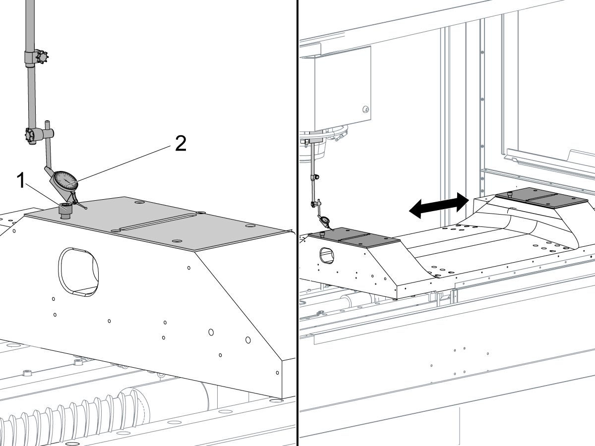
Install a ½-13 screw [1] through each of the spacers and into the receiver tables. Use your fingers to tighten the screws. These hold the spacers in position while you check for flatness.

Put an indicator [2] on the spindle head. Put the tip of the stylus adjacent to the left-hand ½-13 screw. Set the indicator to 0.

Release the [EMERGENCY STOP].

Jog the X Axis until the stylus is adjacent to the right-hand ½-13 screw.

If the spacers are level, the reading on the indicator is no more than 0.0002”. If the reading is more than 0.0002", speak to the Haas Automation Service Department.

Lightly stone the spacers to remove burrs.

Remove the (2) ½-13 screws.

Push [POWER OFF].

3

Remove the shipping brackets from the repaired trunnion assembly.

Connect the A-Axis and B-Axis power and encoder cables to the repaired trunnion.

Push [POWER ON].

Push [EMERGENCY STOP].

Set Parameter 43:3, A axis DISABLED, to 0.

Set Parameter 151:3, B axis DISABLED, to 0.

Cycle power.

Zero return all axes.

Connect the air supply to the repaired trunnion.

4

Jog the A Axis in the negative direction to -180 degrees.

Remove the counterbalance [1]. Remove the (2) inboard hex bolts [2].

Jog the A Axis to 0 degrees.

Push [POWER OFF].

Disconnect the A-Axis and B-Axis power and encoder cables to the repaired trunnion. Do not disconnect the air hoses.

Remove the (2) outboard hex bolts [3].

Attach eye bolts [5] to the top of the trunnion.

Warning: Ensure the air supply is connected to the trunnion assembly. Do not move the trunnion assembly without air pressure.

Lift the repaired trunnion from the shipping bracket.

Warning: The trunnion assembly weighs over 2150 lb (975 kg). Make sure to use a lift of the correct capacity.

Remove the temporary slide keys [4].

Stone the mating surfaces on the bottom of the trunnion assembly.

Install the permanent slide keys that were installed with the machine.

Lower the repaired trunnion onto the receiver table inside the machine.

5

Install the (4) left-hand [1] and (4) right-hand [2] socket-head cap screws through the underside of the receiver table. Do not torque the screws.

Install the (2) outboard hex screws [3]. Do not torque the screws.

Connect the A-Axis and B-Axis power and encoder cables.

6

Push [POWER ON].

Zero return all axes.

Ensure that Parameter 43:20, A axis ROT TRVL LIM is set to 0.

Jog the A Axis in the negative direction to -180 degrees.

Push [EMERGENCY STOP].

Install the (2) inboard hex screws [1]. Do not torque the screws.

Install the counterbalance [2].

Release the [EMERGENCY STOP].

Jog the A Axis to 0 degrees.

VF-5TR, VF-6TR - Integrated Trunnion - Replacement Grid Offset

The grid-offset feature allows you to electronically shift the location of the Z- pulse to 180 degrees from the location of the home switch. This makes sure that the home switch and the Z-pulse do not overlap. It may be necessary to change the grid offset if the belt or the servo motor is replaced.

Parameter 43 Scale X Factor Values

Bit 30 Value Bit 31 Value Scale X Factor
0 0 3
1 0 5
0 1 7
1 1 9

Target Distance

A Axis 0.833
B Axis 0.833

1

Do these steps to calculate the A-Axis grid offset:

  • Zero return the A Axis.
  • Push [POSIT].
  • Subtract the A-Axis value in DIST TO GO from the Target Distance. EXAMPLE:
    • Target Distance = 0.833
    • A-Axis DIST TO GO = 0.700
    • 0.833 - 0.700 = 0.133
  • Multiply the result times the value in Parameter 47, A RATIO (Steps/Unit). EXAMPLE:
    • Value in Parameter 47 = 98304
    • 0.133 x 98304 = 13074
  • Divide the result by the Scale X Factor (from the table above). EXAMPLE:
    • Parameter 43:30, A axis SCALE/X HI = 0
    • Parameter 43:31, A axis SCALE/X LO = 0
    • Scale X factor = 3
    • 13074/3 = 4358
  • Set the value in Parameter 128, A GRID OFFSET, to the result of the calculation. EXAMPLE:
    • Parameter 128 = 4358
  • Zero return the A Axis.

If the calculation is completed correctly, the A-Axis DIST TO GO = 0.833.

2

Do these steps to calculate the A-Axis grid offset:

  • Zero return the A Axis.
  • Push [POSIT].
  • Subtract the A-Axis value in DIST TO GO from the Target Distance. EXAMPLE:
    • Target Distance = 0.833
    • A-Axis DIST TO GO = 0.700
    • 0.833 - 0.700 = 0.133
  • Multiply the result times the value in Parameter 47, A RATIO (Steps/Unit). EXAMPLE:
    • Value in Parameter 47 = 98304
    • 0.133 x 98304 = 13074
  • Divide the result by the Scale X Factor (from the table above). EXAMPLE:
    • Parameter 43:30, A axis SCALE/X HI = 0
    • Parameter 43:31, A axis SCALE/X LO = 0
    • Scale X factor = 3
    • 13074/3 = 4358
  • Set the value in Parameter 128, A GRID OFFSET, to the result of the calculation. EXAMPLE:
    • Parameter 128 = 4358
  • Zero return the A Axis.

If the calculation is completed correctly, the A-Axis DIST TO GO = 0.833.

VF-5TR, VF-6TR - Integrated Trunnion - Alignment

1

MAKE THE A AXIS PARALLEL TO THE X AXIS.

Zero return all axes.

Push [EMERGENCY STOP].

In the next step, you put a mark on opposite sides of the table. The (2) marks must be parallel to each other in the X axis.

2

Put the base of the 0.0005" indicator onto the spindle.

Put the tip of the stylus onto the top of the table adjacent to the edge. Set the indicator to 0.

Release the [EMERGENCY STOP].

Jog the B Axis to -180 degrees.

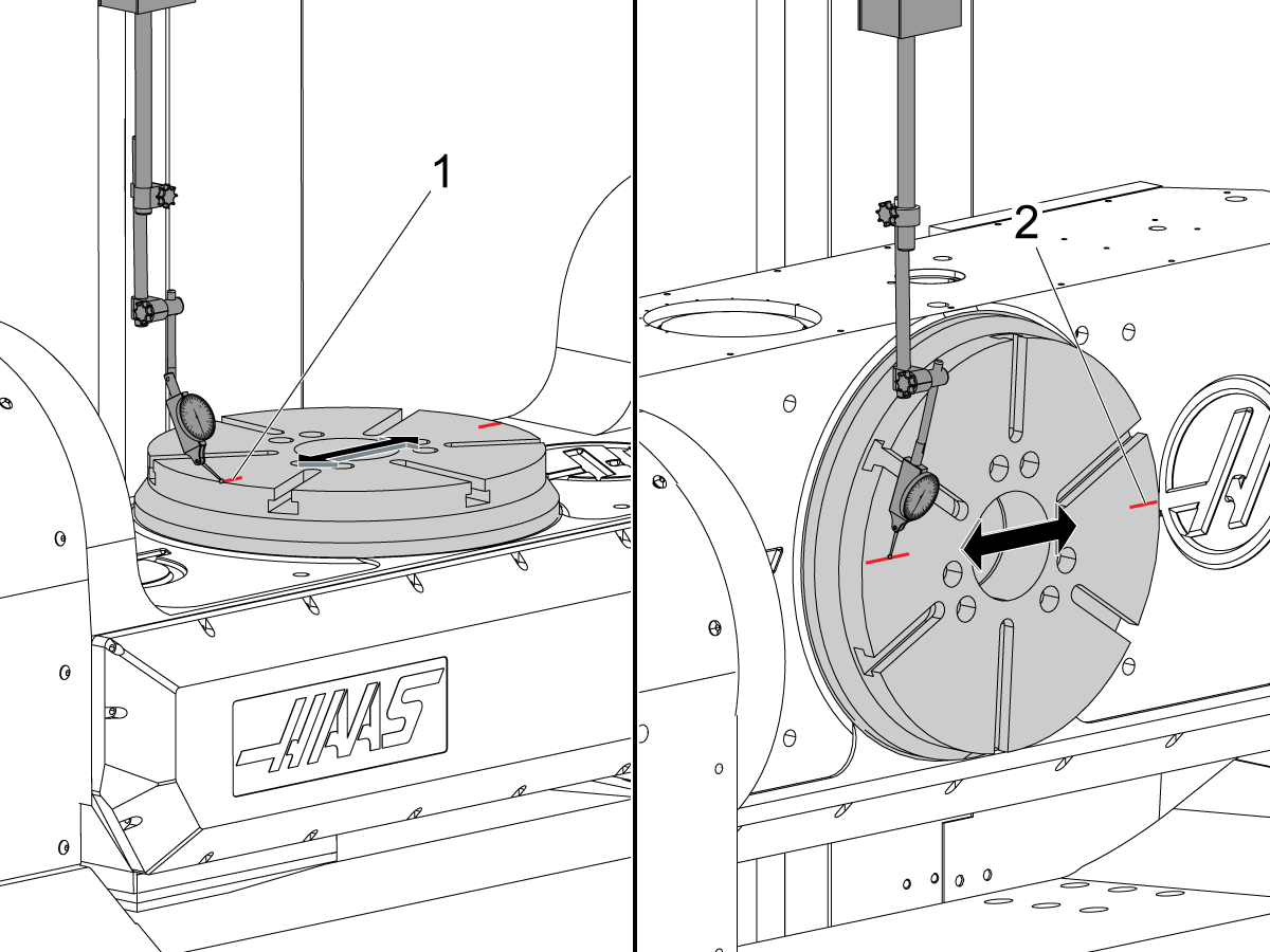
If the indicator still shows 0, put a mark [1] on the table where the stylus touches it.

Jog the B Axis to 0 degrees, the original position.

If the indicator still shows 0, mark the table where the stylus touches it.

If the indicator does not show 0, jog the B Axis in small increments until you can find (2) locations on opposite sides of the table that are at the same height. Mark those locations.

Jog the A Axis in the positive direction to +90 degrees.

Put the tip of the indicator stylus onto one of the marks. Set the indicator to 0.

Jog the X Axis until the stylus is adjacent to the other mark [2].

If the A Axis is parallel to the X Axis, the total indicated runout between the (2) marks is not more than 0.0003". No adjustment is necessary. Go to Step 4.

If the runout is more than 0.0003", go to step 3.

3

Do this step if the total indicated runout between the (2) marks is more than 0.0003".

Determine which end the trunnion must move on the Y Axis to correct the runout.

Loosen the (4) hex screws [1]. Tighten the outboard hex screw on the end that is opposite from the end to be moved. Keep the screw tight enough to control the adjustment.

Strike the base of the trunnion with a dead-blow hammer [2] to move it in the Y Axis. The trunnion pivots around the outboard screw.

Torque the (4) hex screws.

Do Steps 2 and 3 again until the runout is less than 0.0003".

If the runout is still more than 0.0003", loosen the screws on the receiver table. Do steps 2 and 3 again until the runout is not more than 0.0003".

Note: If you loosen the screws on the receiver table, you must align the ballscrew.

4

SET THE A-AXIS BACKLASH.

Jog the A Axis to 0 degrees.

Jog the B Axis until the tee slots on the table are parallel to the X Axis.

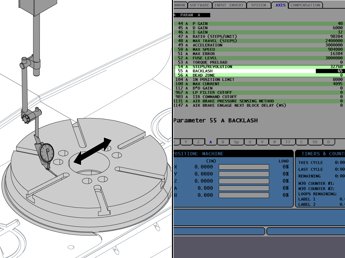
Put an 0.0001" indicator onto the spindle.

Put the tip of the indicator onto a tee slot.

Push [.01/10.].

Jog the A Axis one increment. Watch the indicator.

If the needle on the indicator moved, subtract ten from the value in Parameter 55, A BACKLASH.

If the needle does not move, do these steps:

  • Add 10 to the value in Parameter 55.
  • Jog the A Axis one additional increment. Add 10 to the value in Parameter 55 for each increment you jog until the needle moves.
  • When the needle moves, subtract ten from the value in Parameter 55.

5

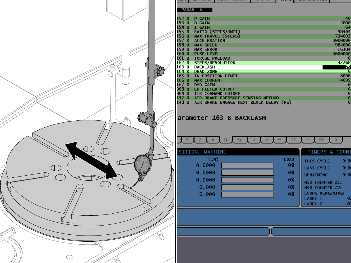
SET THE B-AXIS BACKLASH.

Jog the B Axis until the tee-slots on the table are parallel to the Y Axis.

Put the tip of the indicator onto a tee-slot.

Push [.01/10.].

Watch the indicator.

Jog the B Axis one increment.

If the needle on the indicator moved, subtract 10 from the value in Parameter 163, B BACKLASH.

If the needle did not move, do these steps:

  • Add 10 to the value in Parameter 163.
  • Jog the B Axis one additional increment. Add 10 to the value in Parameter 153 for each increment you jog until the needle moves.
  • When the needle moves, subtract 10 from the value in Parameter 163.

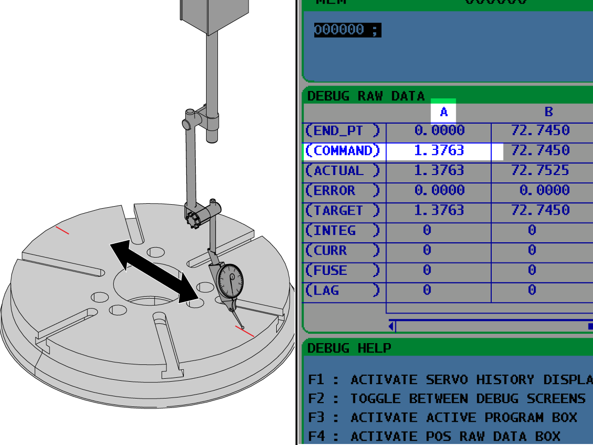
6

SET THE A-AXIS TOOL CHANGE OFFSET.

Zero return the A Axis.

Jog the B Axis until the marks created in Step 1 are parallel to the Y Axis.

In DEBUG mode, set the value of Parameter 212, A TOOL CHANGE OFFSET, to 0.

Push [EMERGENCY STOP].

Put an 0.0001" indicator onto the spindle.

Put the stylus onto one of the marks.

Release the [EMERGENCY STOP].

Push [.0001/.1].

Jog the Y Axis from one mark to the other. Make sure the difference between the (2) marks in the B Axis is not more than 0.0003".

Record the value of A in the COMMAND COLUMN on the POS RAW DATA screen.

Set the value of Parameter 212 to the recorded value of A. The number must be a whole, positive integer.

Zero return the A Axis.

7

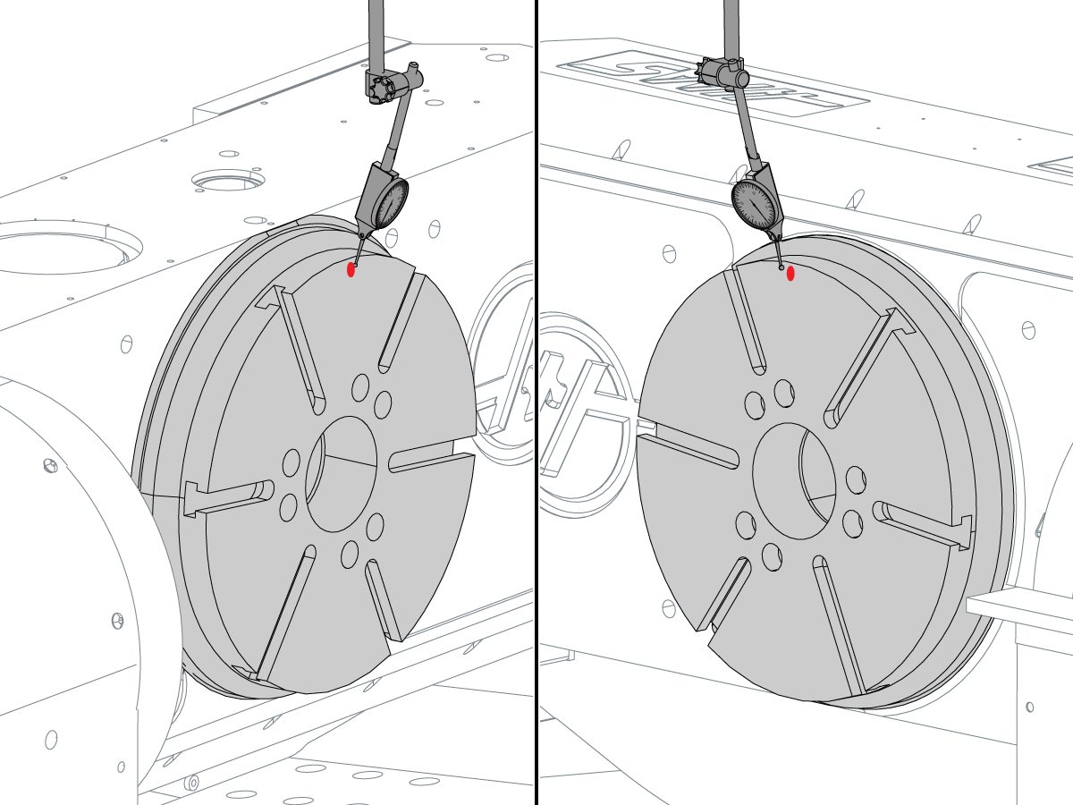
DETERMINE THE CENTER BETWEEN THE A AXIS AND THE B AXIS.

Jog the A Axis in the positive (+) direction to +90 degrees.

Push [EMERGENCY STOP]

Put an 0.0005" indicator between the spindle dogs. Make sure the spindle can turn freely.

Put the tip of the stylus onto the edge of the table.

Release the [EMERGENCY STOP].

Jog the B Axis until you find the highest location on the table. Then, make a mark at that location.

Set the indicator to 0.

Jog the A Axis in the negative (-) direction to -90 degrees.

Jog the B Axis 180 degrees. The marked location is at the top.

Jog the Y Axis until the platter is under the indicator.

Push [EMERGENCY STOP].

Use your hands to turn the spindle until the stylus is against the mark.

If the A Axis and the B Axis are centered relative to each other, the indicator shows a runout of no more than 0.0003".


Recently Viewed Items

You Have No Recently Viewed Items Yet

Feedback
Haas Logo

Haas Delivered Price

This price includes shipping cost, export and import duties, insurance, and any other expenses incurred during shipping to a location in France agreed with you as a buyer. No other mandatory costs can be added to the delivery of a Haas CNC Product.

KEEP UP WITH THE LATEST HAAS TIPS AND TECHNOLOGY...

Sign up now!   

HAAS TOOLING ACCEPTS THE FOLLOWING:

  • Service & Support
  • Owners
  • Request Service
  • Operator Manuals
  • Haas Parts
  • Rotary Repair Request
  • Pre-Install Guides
  • Shopping Tools
  • Build & Price a New Haas
  • Available Inventory
  • The Haas Price List
  • CNCA Financing
  • About Haas
  • Accessibility Statement
  • DNSH Statement
  • Export Compliance
  • Careers
  • Certifications & Safety
  • Contact Us
  • History
  • Terms & Conditions
  • Haas Tooling Terms & Conditions
  • Privacy
  • Warranty
  • Haas Community
  • Haas Certification Program
  • Haas Motorsports
  • Gene Haas Foundation
  • Haas Technical Education Community
  • Events
  • Join the Conversation
  • Facebook
  • X
  • Flickr
  • YouTube
  • LinkedIn
  • Instagram
  • TikTok
© 2026 Haas Automation, Inc – CNC Machine Tools

This site is protected by reCAPTCHA and the Google Privacy Policy and Terms of Service apply.

2800 Sturgis Rd., Oxnard, CA 93030
Toll Free: (888) 817-4446 / Fax: 805-278-8554