×

Search Results

Web Pages

Images

    • <
    • 1
    • >
  • machines
    • Haas Vertical Mills
      Vertical Mills
      • Vertical Mills
      • VF Series
      • Universal Machines
      • VR Series
      • Pallet-Changing VMCs
      • Mini Mills
      • Mold Machines
      • Drill/ Tap/ Mill Series
      • Toolroom Mills
      • Compact Mills
      • Gantry Series
      • Vertical Mill/Turn
      • Extra-Large VMC
      • Double-Column Mills
      • Desktop Mill
      • Mill Auto Parts Loader
    • Product Image
      Multi-Axis Solutions
      • Multi-Axis Solutions
      • 5-Axis Mills
      • Y-Axis Lathes
    • Haas Lathes
      Lathes
      • Lathes
      • ST Series
      • Dual-Spindle
      • Toolroom Lathes
      • Chucker Lathe
      • Haas Bar Feeder V2
      • Lathe Auto Parts Loader
    • Haas Horizontal Mills
      Horizontal Mills
      • Horizontal Mills
      • 50-Taper
      • 40-Taper
    • Haas Rotaries & Indexers
      Rotaries & Indexers
      • Rotaries & Indexers
      • Rotary Tables
      • Indexers
      • 5-Axis Rotaries
      • Extra-Large Rotaries
    • Product Image
      Automation Systems
      • Automation Systems
      • Robot Systems
      • Automatic Parts Loaders
      • Pallet-Pool Systems
      • Haas Bar Feeder
      • Models
    • QUICK LINKS Special Series  Special Series 
      HAAS CAREERS HAAS CAREERS BUILD & PRICE BUILD & PRICE PRICE LIST PRICE LIST WHAT’S NEW WHAT’S NEW YOUR FIRST CNC YOUR FIRST CNC HAAS SIX PACK HAAS SIX PACK
      SHOPPING TOOLS
      • Build & Price a Haas
      • Price List
      • Available Inventory
      • CNCA Financing
      WANT TO TALK TO SOMEONE?

      A Haas Factory Outlet (HFO) can answer your questions, and walk you through your best options.

      CONTACT YOUR DISTRIBUTOR >
  • Options
    • Product Image
      Spindles
      • Spindles
    • Product Image
      Tool Changers
      • Tool Changers
    • Product Image
      4th- | 5th-Axis
      • 4th- | 5th-Axis
    • Product Image
      Turrets & Live Tooling
      • Turrets & Live Tooling
    • Product Image
      Probing
      • Probing
    • Haas Chip & Coolant Management
      Chip & Coolant Management
      • Chip & Coolant Management
    • The Haas Control
      The Haas Control
      • The Haas Control
    • Product Image
      Product Options
      • Product Options
    • Product Image
      Tooling & Fixturing
      • Tooling & Fixturing
    • Product Image
      Workholding
      • Workholding
    • Product Image
      5-Axis Solutions
      • 5-Axis Solutions
      • 5 Easy Steps to 5-Axis
    • Product Image
      Automation
      • Automation
    • QUICK LINKS Special Series  Special Series 
      HAAS CAREERS HAAS CAREERS BUILD & PRICE BUILD & PRICE PRICE LIST PRICE LIST WHAT’S NEW WHAT’S NEW YOUR FIRST CNC YOUR FIRST CNC HAAS SIX PACK HAAS SIX PACK
      SHOPPING TOOLS
      • Build & Price a Haas
      • Price List
      • Available Inventory
      • CNCA Financing
      WANT TO TALK TO SOMEONE?

      A Haas Factory Outlet (HFO) can answer your questions, and walk you through your best options.

      CONTACT YOUR DISTRIBUTOR >
  • Why Haas
      Discover the Haas Difference
      Why Haas MyHaas Education Community Industry 4.0 Haas Certification Customer Testimonials
  • Service
      Welcome to Haas Service
      SERVICE HOME Operator’s Manuals How-To Procedures Troubleshooting Guides Preventive Maintenance Haas Parts Haas Tooling Videos
  • Videos
  • MyHaas – One Place for Everything

    • Compare Quotes
      • Compare Quotes

    • About MyHaas
      • About MyHaas

    • Haas CNC Certification Program
      • Haas CNC Certification Program

    • Haas CNC Certification Program-Redirect
      • Haas CNC Certification Program-Redirect

    • Haas CNC Certification Program
      • Haas CNC Certification Program

    • Haas Learning Resources
      • Haas Learning Resources

    • Haas Global Learning Resources
      • Haas Global Learning Resources

    • MyHaas App Form
      • MyHaas App Form
    • QUICK LINKS Special Series  Special Series 
      HAAS CAREERS HAAS CAREERS BUILD & PRICE BUILD & PRICE PRICE LIST PRICE LIST WHAT’S NEW WHAT’S NEW YOUR FIRST CNC YOUR FIRST CNC HAAS SIX PACK HAAS SIX PACK
      SHOPPING TOOLS
      • Build & Price a Haas
      • Price List
      • Available Inventory
      • CNCA Financing
      WANT TO TALK TO SOMEONE?

      A Haas Factory Outlet (HFO) can answer your questions, and walk you through your best options.

      CONTACT YOUR DISTRIBUTOR >
  • Haas Tooling
      Haas Tooling Mill Toolholding Mill Workholding Milling Lathe Tooling Lathe Toolholding Lathe Workholding ER Collets & Chucks Holemaking Threading Tool Management Tooling Accessories Package Kits Measuring & Inspection Apparel & Accessories
      HAAS TOOLING QUICK LINKS
      NEW PRODUCTS NEW PRODUCTS
      MOST POPULAR MOST POPULAR
      OPEN TERMS OPEN TERMS
      FINANCING FINANCING
      FAQs FAQs
      KITS CREATED FOR YOU KITS CREATED FOR YOU
  • Haas Service Parts
      Haas Service Parts Automatic Pallet Changer Automatic Tool Changer Chip Management Coolant Counterbalance Electrical Cabinet Enclosure Field Install Options Hydraulics Lubrication Maintenance Pendant Probing Rotary Spindle Tailstock
  • Contact Us

My Cart
MyHaas Welcome,
!
Haas Tooling Guest Order History MyHaas/HaasConnect Sign In Register Haas Tooling My Account Order History Return History MyHaas/HaasConnect Sign Out Welcome, My Machines Latest Activity My Quotes My Account My Users Sign Out
Find A Dealer
  1. Select Language
    1. English
    2. Deutsch
    3. Español - España
    4. Español - Méjico
    5. Français
    6. Italiano
    7. Português
    8. Český
    9. Dansk
    10. Nederlands
    11. Magyar
    12. Polski
    13. Svenska
    14. Русский
    15. Türkçe
    16. 中文
    17. Suomi
    18. Norsk
    19. الإنجليزية
    20. български
    21. Hrvatski
    22. Ελληνικά
    23. Română
    24. Slovenský
    25. Slovenščina
    26. 한국어
    27. 日本語
Search
×

Search Results

Web Pages

Images

    • <
    • 1
    • >

Main Processor PCB - Troubleshooting Guide - NGC

Service Home Main Processor PCB - Troubleshooting Guide - NGC
Recently Updated Last updated: 03/14/2022

Main Processor PCB - Troubleshooting Guide - NGC


Main Processor PCB - Troubleshooting Guide - NGC

Jump to Section Back to Top

Introduction

Use this document to troubleshoot the Maincon PCB problems on a machine with the Next Generation Control. If you can not find the scenario that matches your situation, please submit an error log ([SHIFT] + [F3]) to [email protected]

 Note: If necessary the error log command ([SHIFT] + [F3]) can be initiated while the program is running.

Download and fillout the Main Processor PCB Inspection Report Checklist below before replacing any parts.

Main Processor PCB Inspection Report Checklist

Related Videos

Main Processor PCB - Overview

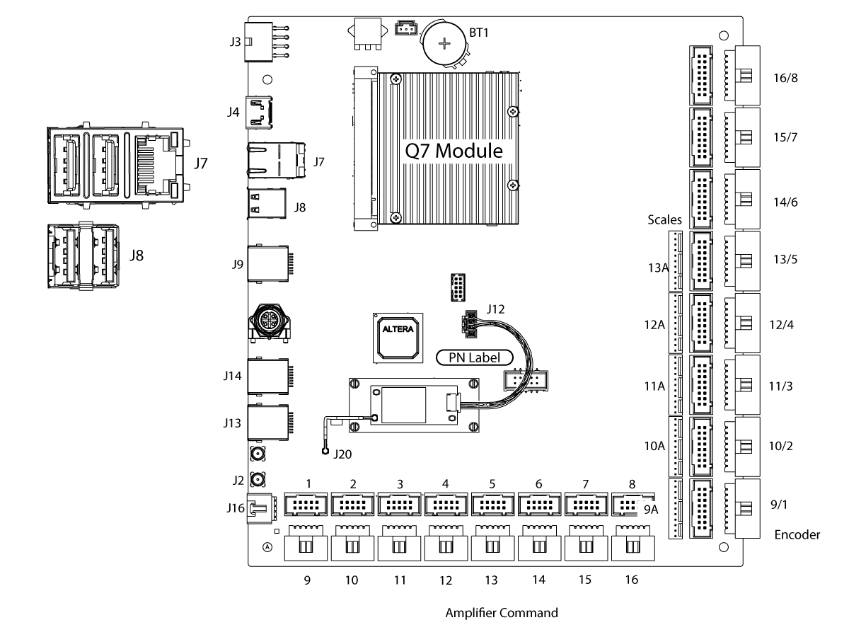
The Next Generation Control Main Processor PCB includes the units for Video, Main, and Motion controller. It accommodates 16 motion control channels. No need to add extra MOCON for the applications that require more channels. This board communicates with the I/O PCB via serial communication through a single RJ45 cable using the RS422 system. The Next Generation Control includes ports for linear scale encoders. Communication with the front panel is done via RJ45 cable and includes the video signals for the LCD display.

  • J3 is the power input connector where +5VDC and +/- 12VDC and a voltage monitor signal is delivered from the PSUP PCB.
  • J7 is a RJ45 ethernet connector and a dual USB hub.
  • The RJ45 ethernet connector is the input from the control cabinet sidewall sheet metal for a wired ethernet connection.
    • The top USB port is connected to the SKBIF PCB at J9.
    • The bottom USB port is not used at this time.
  • J8 is a dual USB hub. It is not used at this time.
  • J9 is a RJ45 ethernet connector. This is connected to the SKBIF PCB at J28.
  • J14 is a RJ45 ethernet connector. This is connected to the I/O PCB at J4.
  • J13 is not used at this time.
  • J2 is a RP-SMA (Reverse-Polarity Sub-Miniature Version A) coaxial connector. This is connected to the WiFi Antenna.
  • J16 is the Voltage Monitor input from the Vector Drive.
  • P1-P16 are the Amplifier Command connections. These are connected to the Axis Servo Amplifiers.
  • P17-P32 are the Axis Encoder input connections. These are the inputs for the Axis Servo motor encoders, axis home sensors, and some rotary air pressure sensors.
  • P33-P37 are the Axis Scale Encoder inputs. These are connected to the secondary scale encoders.
  • BT1 is the System Battery. This provides power to store the date and time memory.
  • The Q7 Module is the Processor board. This module should not be removed.
  • J12 is the WiFi module USB connector. This is connected to the WiFi Module PCB.
  • J20 is a UMCC (Ultra Miniature Coaxial Connector). This is connected to the WiFi Module by a jumper cable.

Main Processor PCB Troubleshooting - Boot Up

1

When powering on the machine the control screen does not boot up and displays a black screen and the LCD backlight is not lit.

Check the following:

  • Check the power input connector at J3 and measure the +5VDC at the connector. The correct voltage will be between +4.90VDC to +5.20VDC.
  • Power off/on the machine a few times and check that the measured voltage stays consistent.
  • If the voltage levels are not consistent. Troubleshoot the PSUP PCB, LVPS, and cables to find the power issue.

Caution: When testing for voltage be careful not to short out the red and black leads. This can cause damage to the Main Processor PCB or the low volt power supply.

2

If you measure the correct voltage consistently at boot up but the control does not boot up and the screen is black. Check the following with the machine powered off:

  • Check the RJ45 ethernet cable and connector from the Main Processor PCB at J9 to the SKBIF PCB at J28. Test the cable, refer to the Network Cable - Tester Tool procedure.
  • Check the connections to the LCD. The LCD data cable at J16 on the SKBIF to the LCD. The LCD Backlight cable from J13 to the LCD. Do not unplug the connections but make check that they are plugged in all the way.

With the machine powered on:

  • Check the Power Input connector at J20 and measure the voltage at the +3.3VDC, +5VDC, and +12VDC test points on the SKBIF. The correct voltages will be between +3.10VDC to +3.50VDC, +4.90VDC to +5.20VDC, and +11.85VDC to +12.40VDC.

3

If the cable connections and measured voltages are correct but the control does not boot up and the screen is black. Perform the following:

  • Update the machine software by holding the U button when powering on the machine.
    • The USB should have your service key, the latest software, and the machine configurations.
    • If the machine boots up and you get the Haas Software Updater screen. Perform an Option 2 software update.
  • If that fails perform an Option 5 software update.
  • If that fails perform a SOFTWARE UPDATE RECOVERY by holding the E button when powering on the machine. This boots from the USB rather than the processor.
  • If the machine does not boot up and display the Haas Software Updater screen. Replace the Main Processor PCB.

4

If the control screen powers on but stops at steps 2-8, this is not a power issue or RJ45 video connection issue, but a Main Processor boot up issue.
This can happen every time at boot up or intermittently. Check the following:

  • Check the Main Processor/Software compatibility table below and upgrade to the latest software.

Note: Do not upgrade to the current software from software version 100.16.000.1020 or lower. You need to upgrade to 100.16.000.1021 first then you can upgrade to the current software version.

  • Perform an Option 2 software update first.
  • If this fails perform an Option 5 software update. If that fails perform a SOFTWARE UPDATE RECOVERY by holding the E button when powering on the machine.
  • If the machine does not boot up and display the Haas Software Updater screen. Replace the Main Processor PCB.

Hardware and Software Version Compatibility Table

NGC Main PCB Compatible Software Version Hardware PN# TP#
NGC maincon PCB with Q7_4GB eMMC module. 100.16.000.1011 and higher (see note*) 32-4250A, 32-4250B, 32-4251B, 32-4252F, 32-4253F N/A
NGC maincon PCB with Q7_8GB eMMC module. 100.17.000.1018 and higher 32-4250C, 32-4250D, 32-4251C, 32-4252A, 32-4253A 20433
NGC maincon PCB with Q7_16GB eMMC module. 100.17.000.2034 and higher 32-4252B, 32-4253B 20566
NGC maincon PCB with IWAVE Q7_16GB eMMC module. 100.20.000.1200 and higher  32-4256, 32-4257 N/A
Y/D Contactor      
Y/D contactor with feedback cables. 100.17.000.2034 and higher 32-5280A, 32-5281A 20007

 Note: Do not upgrade to the current software from software version 100.16.000.1020 or lower. You need to upgrade to 100.16.000.1021 first then you can upgrade to the current software version.

Symptom Table

Symptom Possible Cause Corrective Action

The Time/Date or Activation will reset intermittently.

The system battery is defective. Measure the system battery voltage, if the voltage is below 3.0 VDC replace the battery. Refer to Next Generation Control - Main Control PCB - Battery Replacement
The machine display will not turn on. A loose cable connection to the WIFI module PCB is causing the processor to hang.
  1. Power Off the machine.
  2. Disconnect the WIFI module connector at J12.
  3. Power On the machine. If the machine boots correctly, reseat the WIFI module connector at J12 and also on the WIFI module PCB [1].
The cable from the SKBIF to the Maincon PCB is defective. Refer to the Next Generation Control - SKBIF / LCD Monitor - Troubleshooting Guide for more troubleshooting information.
The screen on the control flickers or goes blank when the servos are on. The cable from the SKBIF to the Maincon PCB is defective. Test the RJ-45 cable that connects to J28 on the SKBIF PCB and J9 on the Maincon PCB using a network cable tester. Refer to Network Cable Tester Tool procedure.
The connector on the SKBIF PCB has a broken solder joint or is not soldered correctly. Check the solder on the J28 header connector on the SKBIF PCB. Make sure that it is soldered correctly. Replace the SKBIF PCB if the connector is not soldered correctly.
The connector on the Maincon PCB has a broken solder joint or is not soldered correctly. Check the solder on the J9 header connector on the Maincon PCB. Make sure that it is soldered correctly. Replace the Maincon PCB if the connector is not soldered correctly.
Machines with software version prior to 100.17.000.2034. The control freezes, blank monitor, black screen, keypad not working, won't boot sometimes, random shutdowns, or software alarms. The parameters for the Q7 module on the Maincon PCB are outdated. The updated parameters have been incorporated into the software version 100.17.000.2034 (TP 21894). Update the software to the latest version. If the symptoms continue after updating the software, download the error log with [SHIFT] + [F3] and e-mail it to Haas Service Department.
Machines with 100.17.000.2040 of later, during a software update you get the following USB error: "The system check detected the USB connector is inserted into the wrong port on the skbif or main board......" The USB cable on the Maincon or SKIBF PCB is connected to the wrong location. Make sure the USB cable going to the SKIBF PCB is connected to the correct location, #2, on the Maincon PCB (See above diagram).
Alarm 488 INTERMITTENT USB ERROR A communication timeout due to a faulty USB device.

Try a different USB device to see if the issue continues. Programs should be run from the control memory and not from the USB. Update the machine to the latest software.

If the alarms continues to generate, take an error report with the alarm present and submit it to Haas Service. Remove the USB device from the side of the pendant. If the alarm does not continue to generate, plug the USB directly into the SKBIF PCB or Main Processor PCB to find the faulty cable or PCB. If it does continue to generate, disconnect the other USB devices. See the Alarms 9100.017 & 9100.018 section below for steps.

Watch the video below and follow the troubleshooting done.

USB Cable - Troubleshooting

The control freezes. Faulty USB stick or USB hub on the Main Processor PCB or SKBIF PCB.

Try a different USB device to see if the issue continues. Programs should be run from the control memory and not from the USB.

If the control freezes and the machine is unresponsive, Cycle Power the machine and take an error report and submit it to Haas Service. If the issue does not continue. Install the USB to the bottom port of J21 on the SKBIF PCB. If no, replace the cable from the pendant to the SKBIF PCB.

The control has a laggy/delayed response. Faulty USB stick or USB hub on the Main Processor PCB or SKBIF PCB.

Try a different USB device to see if the issue continues. Programs should be run from the control memory and not from the USB.

If the control is laggy, remove the USB stick from the side of the pendant. If the issue continues, take an error report at the time of the issue and submit it to Haas Service. If it does not continue, install the USB to the bottom port of J21 on the SKBIF PCB. If the issue continues, take an error report at the time of the issue and submit it to Haas Service. If it doesnt continue replace the cable from the pendant to the SKBIF PCB.

Alarms 9100.017 or 9100.018 NON RESETTABLE SOFTWARE ERROR is generated on machines with software version 100.21.000.1133 and lower. A communication timeout due to a faulty USB component.

Update the machine to the latest software. If the alarms continues to generate, take an error report with the alarm present and submit it to Haas Service. Disconnect the following USB devices to troubleshoot the USB device causing the alarm:

•USB drive on pendant.
•Touchscreen and disable the setting
•Wi-Fi and disable the Wireless Connection
•Robot Signal and disable the setting

See the Alarms 9100.017 & 9100.018 section below for steps.

Alarm 9011 WIFI MODULE ERROR A communication timeout due to a faulty Wi-Fi USB device.

If installed, remove the USB device from the side of the pendant. Update the machine to the latest software. If the alarms continues to generate, take an error report with the alarm present and submit it to Haas Service.

Disconnect the Wi-Fi at J12 on the Main Processor PCB and Disable the Wireless Connection in Settings > Network > Wireless Connection and press F1 to Disconnect. Cycle power the machine. Does the alarm continue to generate?

•If no, replace the Main Processor PCB.
•If yes, disconnect the other USB devices.

Alarm 9012 ETHERNET ADAPTER ERROR A communication timeout due to a faulty Robot signal USB device.

If installed, remove the USB device from the side of the pendant. Update the machine to the latest software. If the alarms continues to generate, take an error report with the alarm present and submit it to Haas Service.

Disconnect the Robot Signal cable at J8 on the Main Processor PCB and disable the Robot by changing Setting 372 – Part Loader Type to 0: Off.

•Does the alarm continue to generate? If no, replace the Main Processor PCB.
•If yes, disconnect the other USB devices.

PCB Component Inspection

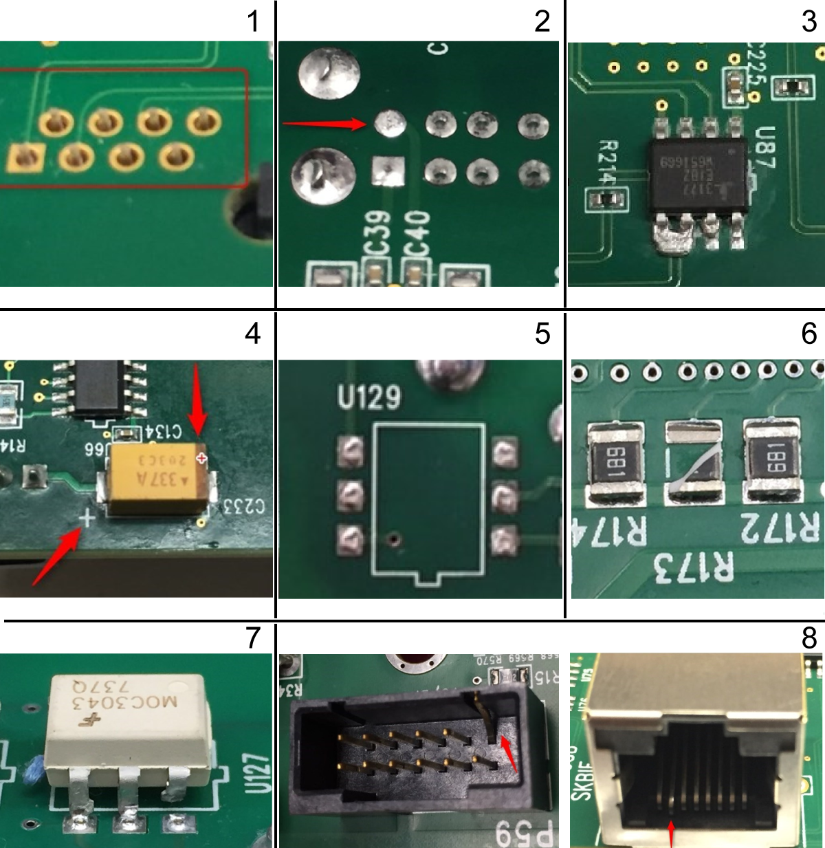
Intermittent symptoms or alarms can be caused by component failure. Below is a list of possible failures:

  1. Missing solder on all or some components pins
  2. Poor solder
  3. Solder bridges
  4. Wrong component installation (orientation)
  5. Missing components

     Note: Some PCB's have unused circuits and are missing components intentionally, look for broken off components.

  6. Broken components
  7. Broken pins on IC's
  8. Bent pins on the connectors

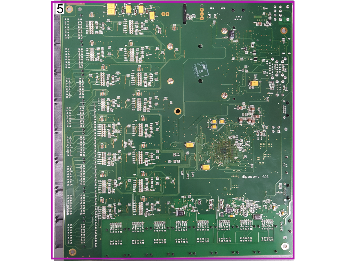
Use a magnifying glass to inspect the circuit components on the front and back of the Maincon PCB. Below are the circuit component zones to inspect:

  1. Inspect for bent pins inside the connectors, also look for loose header connectors.
  2. Inspect for a loose battery, broken battery tabs, repair if needed.

     Note: Do not replace the Maincon PCB. Refer to Next Generation Control - Main Control PCB - Battery Replacement for repair instructions.

  3. Inspect for bent or missing pins inside the connectors, also look for loose header connectors.
  4. Inspect the E-net module for loose connections or broken wires.
  5. Inspect all solder joints and surface mount components on the back of the Maincon PCB.
FIND DISTRIBUTOR
Feedback
Haas Logo

美元价格不包括关税、报关费用、保险费、增值税及运费。
USD prices DO NOT include customs duty, customs fees, insurance, VAT, or freight.

人民币价格包含关税、报关费用、货运保险和增值税, 但不包括运费。
CNY prices include customs duty, customs fees, insurance, and VAT. DOES NOT include freight.

Haas Delivered Price

This price includes shipping cost, export and import duties, insurance, and any other expenses incurred during shipping to a location in France agreed with you as a buyer. No other mandatory costs can be added to the delivery of a Haas CNC Product.

KEEP UP WITH THE LATEST HAAS TIPS AND TECHNOLOGY...

Sign up now!   

HAAS TOOLING ACCEPTS THE FOLLOWING:

  • Service & Support
  • Owners
  • Request Service
  • Operator Manuals
  • Haas Parts
  • Rotary Repair Request
  • Pre-Install Guides
  • Shopping Tools
  • Build & Price a New Haas
  • Available Inventory
  • The Haas Price List
  • CNCA Financing
  • About Haas
  • Careers
  • Certifications & Safety
  • Contact Us
  • History
  • Terms & Conditions
  • Haas Tooling Terms & Conditions
  • Privacy
  • Warranty
  • Haas Community
  • Haas Certification Program
  • Haas Motorsports
  • Gene Haas Foundation
  • Haas Technical Education Community
  • Events
  • Join the Conversation
  • Facebook
  • Twitter
  • Flickr
  • YouTube
  • LinkedIn
  • Instagram
  • TikTok
© 2022 Haas Automation, Inc – CNC Machine Tools

2800 Sturgis Rd., Oxnard, CA 93030 / Toll Free: 800-331-6746
Phone: 805-278-1800 / Fax: 805-278-2255

Cookie Notice

We use cookies to improve your user experience. Our Cookie Notice describes which cookies we use, why we use them, and how you can find more information about them. Please confirm you consent to us using analytics cookies. If you do not consent, you may still use our website with a reduced user experience.

Manage Settings

Cookie Notice

We use cookies to improve your user experience. Our Cookie Notice describes which cookies we use, why we use them, and how you can find more information about them. Please confirm you consent to us using analytics cookies. If you do not consent, you may still use our website with a reduced user experience.

Functional Cookies

Analytics Cookies