×

Search Results

Web Pages

Images

    • <
    • 1
    • >
  • machines
    • Haas Vertical Mills
      Vertical Mills
      • Vertical Mills
      • VF Series
      • Universal Machines
      • VR Series
      • Pallet-Changing VMCs
      • Mini Mills
      • Mold Machines
      • Drill/ Tap/ Mill Series
      • Toolroom Mills
      • Compact Mills
      • Gantry Series
      • Vertical Mill/Turn
      • Extra-Large VMC
      • Double-Column Mills
      • Desktop Mill
      • Mill Auto Parts Loader
    • Product Image
      Multi-Axis Solutions
      • Multi-Axis Solutions
      • 5-Axis Mills
      • Y-Axis Lathes
    • Haas Lathes
      Lathes
      • Lathes
      • ST Series
      • Dual-Spindle
      • Toolroom Lathes
      • Chucker Lathe
      • Haas Bar Feeder V2
      • Lathe Auto Parts Loader
    • Haas Horizontal Mills
      Horizontal Mills
      • Horizontal Mills
      • 50-Taper
      • 40-Taper
    • Haas Rotaries & Indexers
      Rotaries & Indexers
      • Rotaries & Indexers
      • Rotary Tables
      • Indexers
      • 5-Axis Rotaries
      • Extra-Large Rotaries
    • Product Image
      Automation Systems
      • Automation Systems
      • Robot Systems
      • Automatic Parts Loaders
      • Pallet-Pool Systems
      • Haas Bar Feeder
      • Models
    • QUICK LINKS Special Series  Special Series 
      HAAS CAREERS HAAS CAREERS BUILD & PRICE BUILD & PRICE PRICE LIST PRICE LIST WHAT’S NEW WHAT’S NEW YOUR FIRST CNC YOUR FIRST CNC HAAS SIX PACK HAAS SIX PACK
      SHOPPING TOOLS
      • Build & Price a Haas
      • Price List
      • Available Inventory
      • CNCA Financing
      WANT TO TALK TO SOMEONE?

      A Haas Factory Outlet (HFO) can answer your questions, and walk you through your best options.

      CONTACT YOUR DISTRIBUTOR >
  • Options
    • Product Image
      Spindles
      • Spindles
    • Product Image
      Tool Changers
      • Tool Changers
    • Product Image
      4th- | 5th-Axis
      • 4th- | 5th-Axis
    • Product Image
      Turrets & Live Tooling
      • Turrets & Live Tooling
    • Product Image
      Probing
      • Probing
    • Haas Chip & Coolant Management
      Chip & Coolant Management
      • Chip & Coolant Management
    • The Haas Control
      The Haas Control
      • The Haas Control
    • Product Image
      Product Options
      • Product Options
    • Product Image
      Tooling & Fixturing
      • Tooling & Fixturing
    • Product Image
      Workholding
      • Workholding
    • Product Image
      5-Axis Solutions
      • 5-Axis Solutions
      • 5 Easy Steps to 5-Axis
    • Product Image
      Automation
      • Automation
    • QUICK LINKS Special Series  Special Series 
      HAAS CAREERS HAAS CAREERS BUILD & PRICE BUILD & PRICE PRICE LIST PRICE LIST WHAT’S NEW WHAT’S NEW YOUR FIRST CNC YOUR FIRST CNC HAAS SIX PACK HAAS SIX PACK
      SHOPPING TOOLS
      • Build & Price a Haas
      • Price List
      • Available Inventory
      • CNCA Financing
      WANT TO TALK TO SOMEONE?

      A Haas Factory Outlet (HFO) can answer your questions, and walk you through your best options.

      CONTACT YOUR DISTRIBUTOR >
  • Why Haas
      Discover the Haas Difference
      Why Haas MyHaas Education Community Industry 4.0 Haas Certification Customer Testimonials
  • Service
      Welcome to Haas Service
      SERVICE HOME Operator’s Manuals How-To Procedures Troubleshooting Guides Preventive Maintenance Haas Parts Haas Tooling Videos
  • Videos
  • Haas Tooling
      Haas Tooling Mill Toolholding Mill Workholding Milling Lathe Tooling Lathe Toolholding Lathe Workholding ER Collets & Chucks Holemaking Threading Tool Management Tooling Accessories Package Kits Measuring & Inspection Apparel & Accessories
      HAAS TOOLING QUICK LINKS
      NEW PRODUCTS NEW PRODUCTS
      MOST POPULAR MOST POPULAR
      OPEN TERMS OPEN TERMS
      FINANCING FINANCING
      FAQs FAQs
      KITS CREATED FOR YOU KITS CREATED FOR YOU
  • Haas Service Parts
      Haas Service Parts Automatic Pallet Changer Automatic Tool Changer Chip Management Coolant Counterbalance Electrical Cabinet Enclosure Field Install Options Hydraulics Lubrication Maintenance Pendant Probing Rotary Spindle Tailstock
  • Contact Us

My Cart
MyHaas Welcome,
!
Haas Tooling Guest Order History MyHaas/HaasConnect Sign In Register Haas Tooling My Account Order History Return History MyHaas/HaasConnect Sign Out Welcome, My Machines Latest Activity My Quotes My Account My Users Sign Out
Find A Dealer
  1. Select Language
    1. English
    2. Deutsch
    3. Español
    4. Français
    5. Italiano
    6. Português
    7. Český
    8. Dansk
    9. Nederlands
    10. Magyar
    11. Polski
    12. Svenska
    13. Русский
    14. Türkçe
    15. 中文
    16. Suomi
    17. Norsk
    18. الإنجليزية
    19. български
    20. Hrvatski
    21. Ελληνικά
    22. Română
    23. Slovenský
    24. Slovenščina
    25. 한국어
    26. 日本語
Search
×

Search Results

Web Pages

Images

    • <
    • 1
    • >

4 - PulseJet System

Lubrication Systems - Service Manual


  • 1 - Lube Systems - Introduction
  • 2 - Haas Liquid Grease
  • 3 - Minimum Quantity Lubrication
  • 4 - PulseJet System

Go To :

  • 4.1 PulseJet - Installation
  • 4.2 PulseJet - Service Replacement
  • 4.3 PulseJet - Lubrication Chart
  • 4.4 PulseJet - Troubleshooting
Recently Updated

PulseJet - Installation


AD0454

Introduction

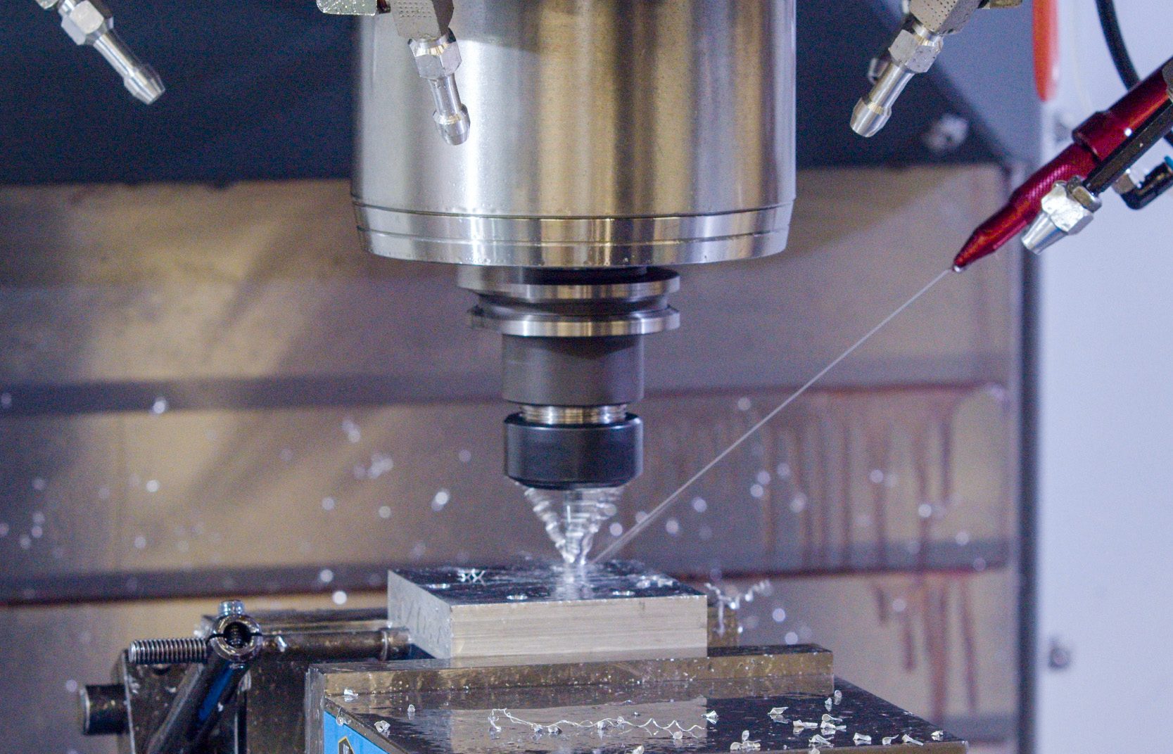
This procedure will show you how to install a PulseJet on VMC/UMC mills.

Machine Requirements:

  • VMC/UMC built on October 2019 or later.
  • 100.19.000.1123 Software Version or higher.
  • Programmable Coolant option

Video Instructions

Hoses and Sensor Cable Installation

Note:  This section is required for field installations, go to the next section if the Pulsejet option was purchased from the factory.

1

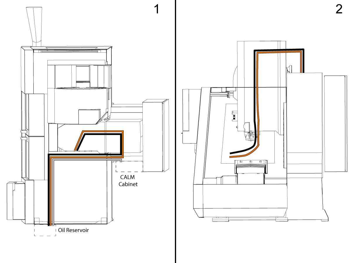
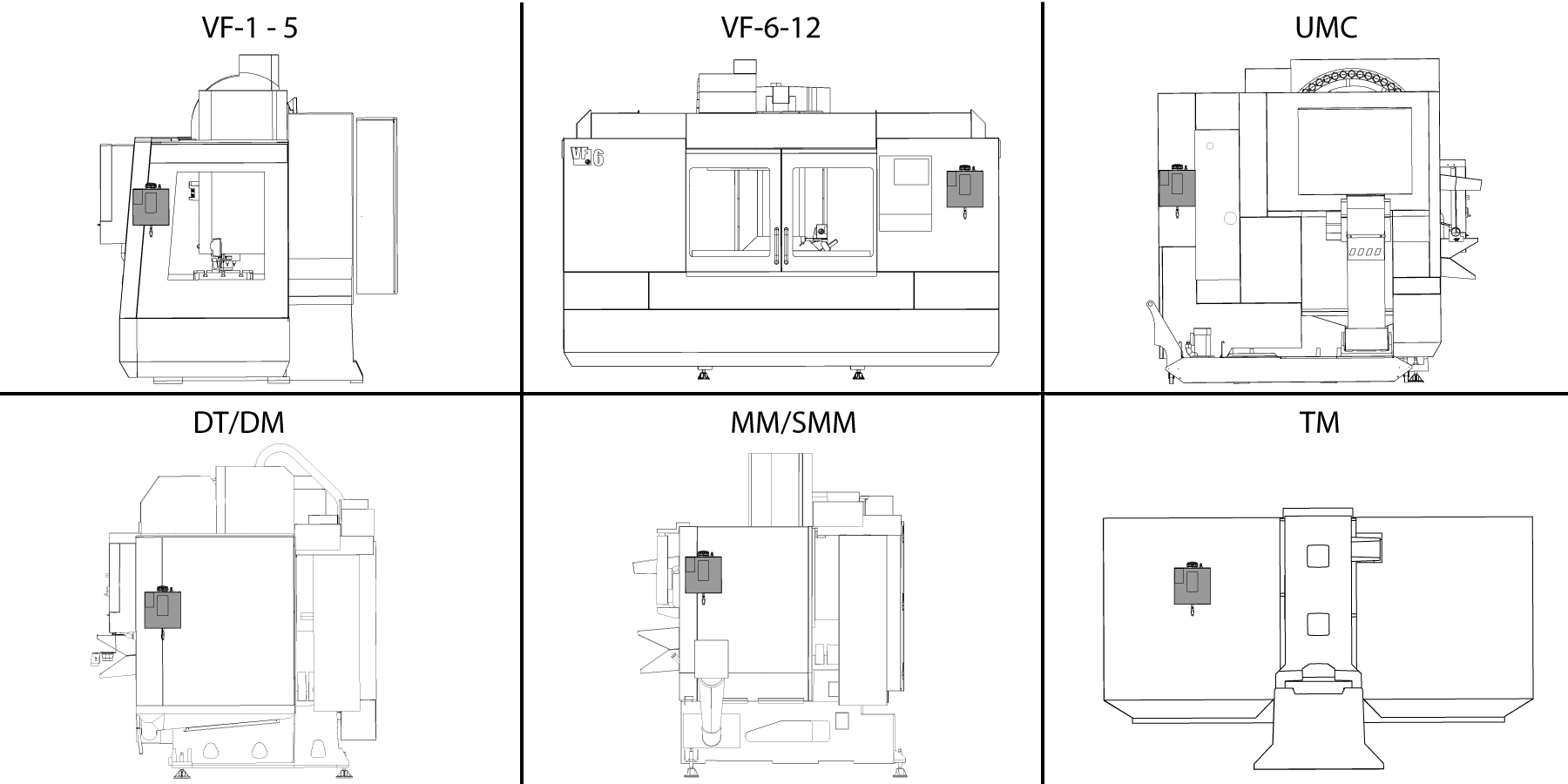
The illustration shows the PulseJet hose routing on a VF-2: 1: Top View 2: Side View.

Route the nozzle air hose (1/4 inch black hose) from the CALM cabinet, through spindle head,  towards the PulseJet/PCool location.

Route the nozzle oil hose (5/32 inch clear hose): from the Oil reservoir, up onto the roof, into cable carrier, through spindle head, towards the PulseJet/Pcool location.

Route the Oil Reservoir air hose (1/4 inch clear hose) from CALM cabinet solenoid towards the Oil Reservoir location.

Note:  Make sure you leave enough slack at both ends.

2

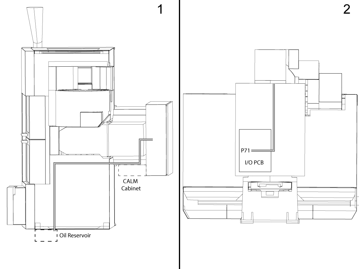
Route the Oil Reservoir level sensor cable from the Oil Reservoir location, to the top of the roof to the electrical cabinet.

Note: Make sure you leave enough slack to connect the cable to the Oil Reservoir sensor.

Plug in the cable to the I/O PCB at P71.

PulseJet & Tank Installation

1

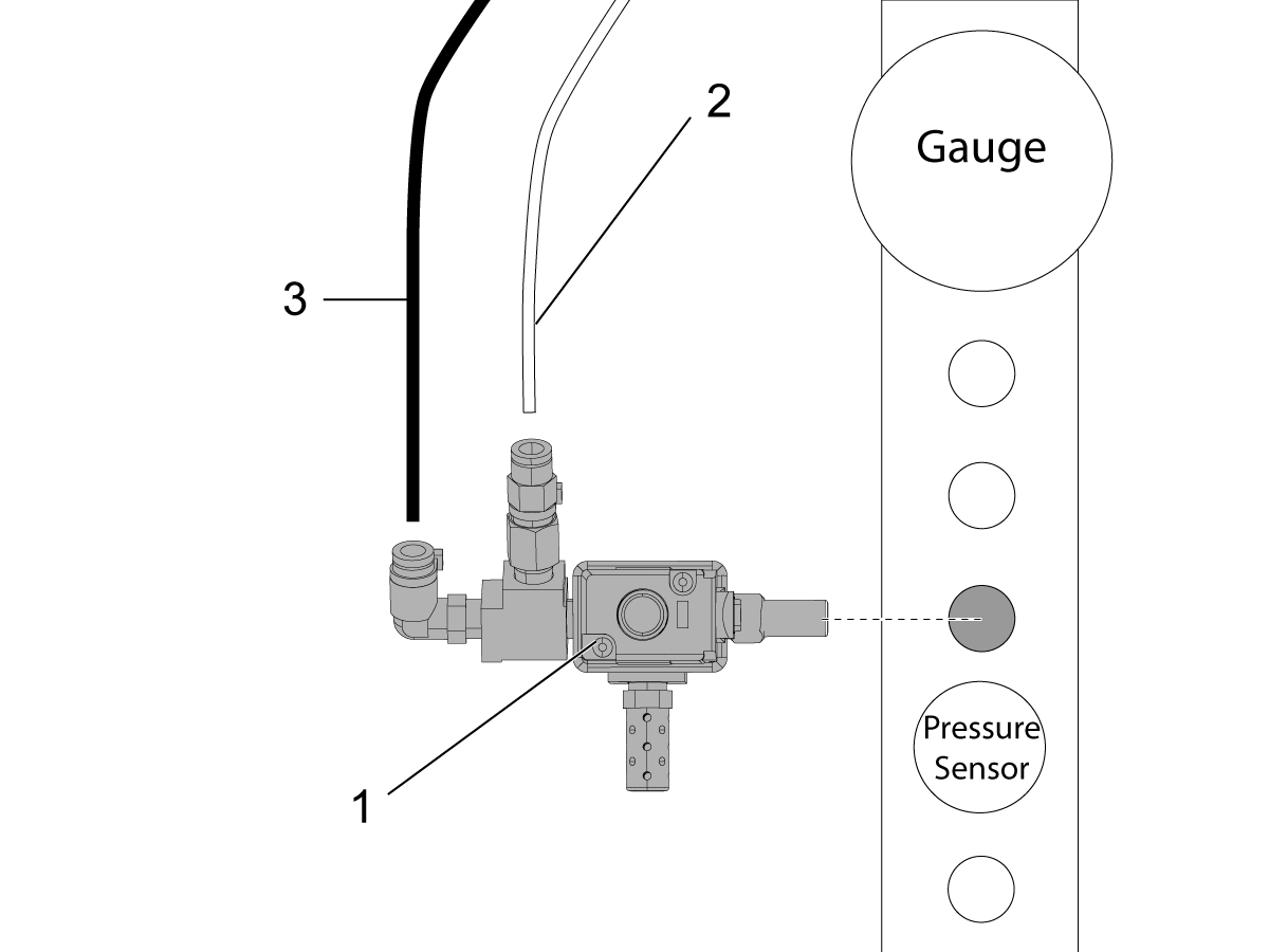
Turn off air to the machine.

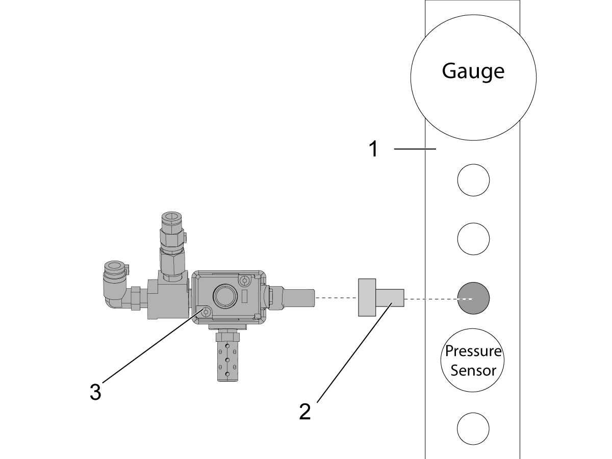
Locate the air manifold [1], remove the third NPT plug below the air gauge.

Install the adapter fitting P/N 58-1521 [2] into the manifold.

Install the solenoid valve [3] oriented as shown.

Connect the solenoid cable to the connector panel labeled "PULSEJET".

2

Unpack the PulseJet nozzle assembly.

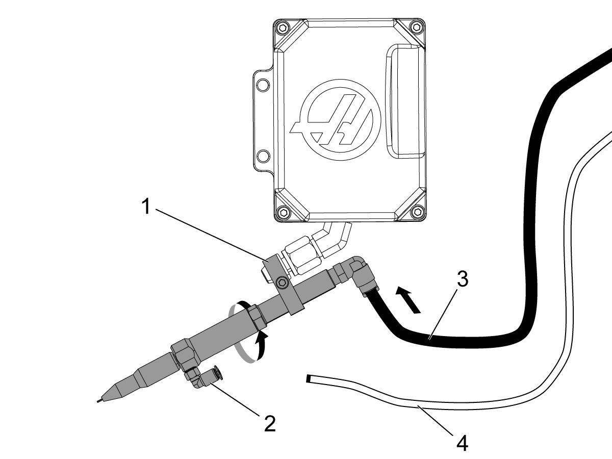
Loosen the clamp screw [1] and slide the clamp and the PulseJet assembly onto the P-COOL nozzle.

Adjust the PulseJet nozzle so that the oil inlet fitting [2] is on the bottom. 

Aim the nozzle approximately at the spindle centerline (it will be adjusted later).

Tighten the clamp set screw.

Find the 1/4” black air hose [3] and connect it to the air fitting on the nozzle assembly.
Find the 5/32” clear oil hose [4] but DO NOT connect it to the oil fitting.  This hose will be connected during the prime procedure.

3

Mount the Oil Reservoir to the machine enclosure, refer to the illustration.

The oil resevoir assembly has magnets for easy mounting. 

Important: Do not slide the magnets on the enclosure. Instead, if you need to move the reservoir, tilt it to detach the magnets and then gently set it back down.

4

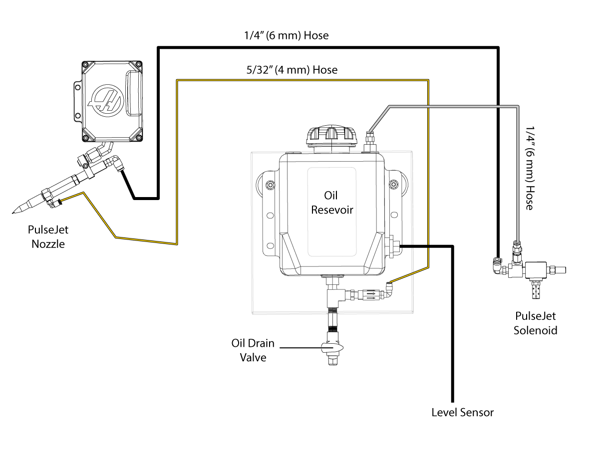
Connect the cable and air hoses to the Oil Reservoir assembly refer to the diagram.

Connect the air hoses to the solenoid. 

  Important: Make sure to connect the correct hoses to the solenoid, matching the color zip ties. If the hoses are swapped, it will send high pressure to the tank and could rupture the tank.

5

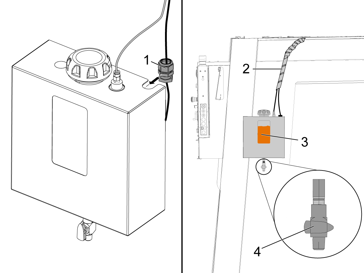
Slide the strain relief [1] into the slot on the reservoir assembly and tighten the retaining nut.

Apply the supplied spiral wrap [2] from the enclosure to the top of the machine to help neatly organize and secure the cables.

Make sure the drain valve on the bottom of the reservoir is in the closed (horizontal) position [4].

Remove the reservoir cap and fill the tank with oil [3].  Do not overfill the tank.
Note: The tank requires air space above the oil to maintain positive pressure above the oil.

Reinstall cap.

Prime the Oil Line

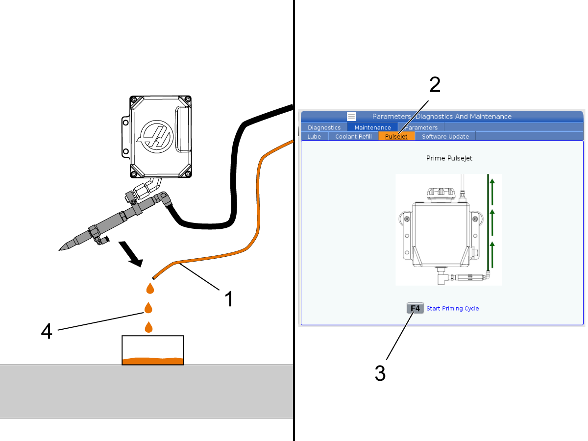
Make sure there is oil in the PulseJet reservoir and that the lid is tightly installed. Make sure the reservoir air and oil lines are connected. 

Disconnect the oil line [1] from the PulseJet nozzle and let it drape over a container placed on the mill table.

Press [DIAGNOSTIC] and navigate to the Maintanance then to the PulseJet tab [2]. 

Press [F4] to begin a priming cycle. Each cycle lasts 10 minutes.  The reservoir will be pressurized during the cycle. 

Note: Small machines may take only 1 cycle to fully prime the line. Larger machines may take 3 or 4 cycles. Heavier oils may take longer to prime. Continue running priming cycles until oil [4] begins to drip out of the oil line into the container. 

Note: While the machine is in the prime cycle the user can start a program.   However the user will not be able to start the prime cycle again while the program is running.

Reconnect the oil line to the PulseJet nozzle.

In MDI run:

M162 P10;
G04 P10.;
M30;

Test the PulseJet until a strong stream develops. 

PulseJet M-codes

M-CODE

DESCRIPTION

WHAT IT’S USED FOR

M160

Cancel Active PulseJet

To cancel an active PulseJet M-code.

M161 Pnn

Continuous Mode

Will turn PulseJet on whenever a feed move is active in a program. Pnn is how many seconds between oil pulses. Min = 1 sec Max = 99 sec

M162 Pnn

Single Event Mode

Will turn on PulseJet for a defined number of pulses. Pnn is how many pulses. Best used for drilling and tapping or to manually lubricate a tool.
Note:  M162 Pnn Is a non-blocking code.  Anything after the code will be executed immediately.

M163 Pnn

Modal Mode

Activates PulseJet to turn on during any canned drill or tap cycles. Pnn is how many pulses for each hole.

Note: Any PulseJet M-code will override any active previous PulseJet M-code.  
Note: Settings 369 and 370 can be used to change the default values for M161 and M162 when no P is specified.

Tips and Troubleshooting

1.       PulseJet will produce a consistent, fast, and tight oil pulse if the line is well primed, the dispenser needle is not clogged, and a recommended oil is being used.

2.       To always keep the line well primed:

  • Place the reservoir assembly near or above the spindle elevation
  • never let the tank run completely dry

3.       If you suspect that the dispenser needle is clogged, replace it. To do this, unscrew the knurled nozzle cap from the nozzle and gently twist and pull the yellow base of the needle off of the nozzle.

Note: This will expose the small check valve spring, do not lose it. Firmly press the replacement needle onto the nozzle taper. Re-install the nozzle cap finger tight.

4.       Use recommended oil: light viscosity oils and tapping or cutting fluids work the best. Heavy viscosity oils such as motor oil, gear oil, or heavy tapping oils may not produce a high-quality stream.

5.       If the oil line does get air bubbles inside, the pump inside the PulseJet nozzle will pass them through the system. While bubbles are moving through the nozzle, the stream will appear weak, aerated, and inconsistent. After the bubbles pass through, the stream will return to its proper form.

6.       Always make sure the reservoir cap is installed and tightened when running PulseJet to maintain the proper tank pressure.

PulseJet Lubrication

Refer to Lubricant Grease, and Sealant Table to see our recommended oil list.

Recently Updated

Pulsejet - Service Replacement


AD0511

Introduction

Use this procedure to replace the following Pulsejet components in the field:

  • 93-30-12599    Pulsejet nozzle assembly
  • 93-30-12603    PulseJet solenoid assembly
  • 93-30-12600    PulseJet tank assembly

Note: If installing the PulseJet option for the first time, do not use this document.  Refer to Pulsejet - Installation procedure.

Nozzle Replacement

1

To remove the pulsejet nozzle:

  • Disconnect the air and oil lines.
    Note: Inspect the lines for damage or kinks, and replace them if necessary.
  • Loosen the clamp screw [1] and slide the PulseJet nozzle out of the P-COOL nozzle.
    Important: Support the P-COOL nozzle while you loosen the clamp screw.

Unpack the PulseJet nozzle assembly.

  • Loosen the clamp screw [1] and slide the clamp and the PulseJet assembly onto the P-COOL nozzle.
     Important: Support the P-COOL nozzle while you tighten the clamp screw.
  • Adjust the PulseJet nozzle so that the oil inlet fitting [2] is on the bottom. 
  • Aim the nozzle approximately at the spindle centerline (it will be adjusted later).

Tighten the clamp set screw.

Find the 1/4” black air line [3] and connect it to the air fitting on the nozzle assembly.
Find the 5/32” clear oil line [4] connect it to the oil fitting. 

Command 10-20 pulses until oil is properly streaming out of the nozzle.

 Note: If you are only replacing the nozzle (and not the tank) you do not need to run a full priming cycle.

Solenoid Replacement

1

Turn off air to the machine.

Locate the PulseJet solenoid [1].

Disconnect the two air lines [2,3] from the solenoid.

Important:  Mark the position of the two air lines, they will need to be installed in the same position.

Disconnect the solenoid cable from the connector bracket.

Remove the old solenoid and install the new one.

Connect the air lines to the solenoid.

Note:  The 1/4" clear line [2] attahced to the port with an orifice.  The 1/4" black line [3] connects to the port with no orifice.  

Connect the solenoid cable to the connector panel labeled "PULSEJET".

Turn on the incoming air and test the PulseJet.

Tank Replacement

1

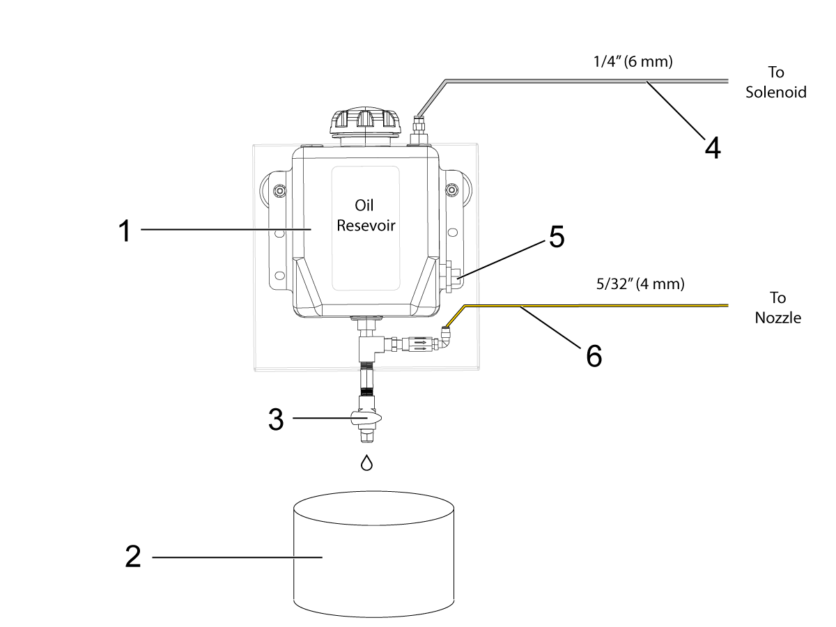
Locate the tank [1] assembly on the side of the machine.

Place a large container [2] to drain the oil (at least 3 quarts).  

Note: if you plan to re-use the oil, the container must be thoroughly cleaned.

Open the valve [3] to let it completely drain. Loosen the tank cap to speed up the draining.

Once the oil is drained, close the drain valve.

Carefully lift the magnetic tank off the machine using a tilting motion. Turn the tank so that you can access the rear of the tank.

Carefully disconnect the air line [4] and oil level sensor [5].

Disconnect the oil line [6].

Note: Oil may flow back through the line, so have a container to place the line in to catch the oil.

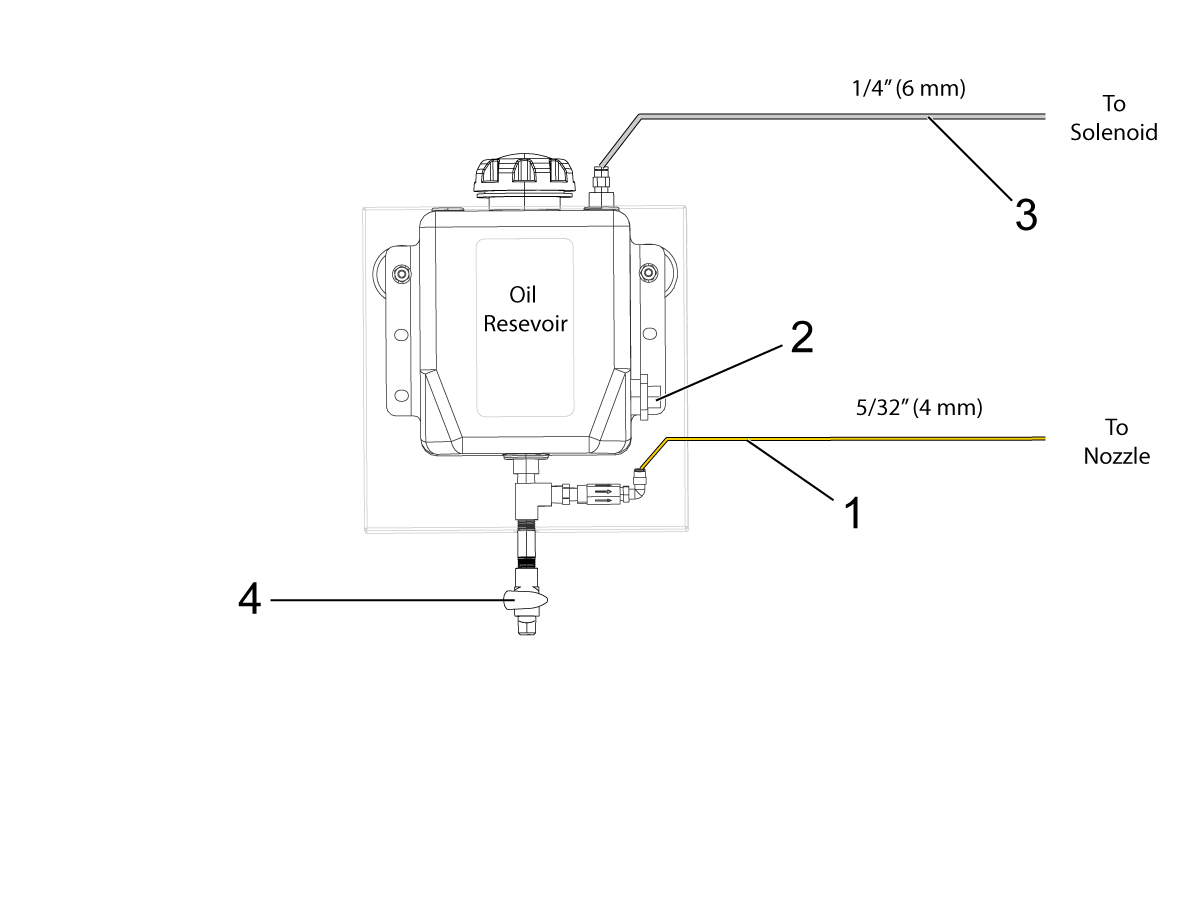
2

Connect the 5/32" oil line [1], level sensor cable [2] and the 1/4"  tank air line  (see diagram).

Carefully install the tank to the side of the machine with the magnets.

Make sure the drain valve [4] is closed.

Open the tank cap and re-fill the tank with oil. Firmly replace cap until it “clicks”.

There will be air trapped inside the system from disconnecting and reconnecting the oil line. This air must be purged out before PulseJet can be used effectively. 

Refer to the Prime the Oil Line section in this document.

Prime the Oil Line

Make sure there is oil in the PulseJet reservoir and that the lid is tightly installed. Make sure the reservoir air and oil lines are connected. 

Disconnect the oil line [1] from the PulseJet nozzle and let it drape over a container placed on the mill table.

Press [DIAGNOSTIC] and navigate to the Maintanance then to the PulseJet tab [2]. 

Press [F4] to begin a priming cycle. Each cycle lasts 10 minutes.  The reservoir will be pressurized during the cycle. 

Note: Small machines may take only 1 cycle to fully prime the line. Larger machines may take 3 or 4 cycles. Heavier oils may take longer to prime. Continue running priming cycles until oil [4] begins to drip out of the oil line into the container. 

Note: While the machine is in the prime cycle the user can start a program.   However the user will not be able to start the prime cycle again while the program is running.

Reconnect the oil line to the PulseJet nozzle.

In MDI run:

M162 P10;
G04 P10.;
M30;

Test the PulseJet until a strong stream develops. 

Tips and Troubleshooting

1.       PulseJet will produce a consistent, fast, and tight oil pulse if the line is well primed, the dispenser needle is not clogged, and a recommended oil is being used.

2.       To always keep the line well primed:

  • Place the reservoir assembly near or above the spindle elevation
  • never let the tank run completely dry

3.       If you suspect that the dispenser needle is clogged, replace it. To do this, unscrew the knurled nozzle cap from the nozzle and gently twist and pull the yellow base of the needle off of the nozzle.

Note: This will expose the small check valve spring, do not lose it. Firmly press the replacement needle onto the nozzle taper. Re-install the nozzle cap finger tight.

4.       Use recommended oil: light viscosity oils and tapping or cutting fluids work the best. Heavy viscosity oils such as motor oil, gear oil, or heavy tapping oils may not produce a high-quality stream.

5.       If the oil line does get air bubbles inside, the pump inside the PulseJet nozzle will pass them through the system. While bubbles are moving through the nozzle, the stream will appear weak, aerated, and inconsistent. After the bubbles pass through, the stream will return to its proper form.

6.       Always make sure the reservoir cap is installed and tightened when running PulseJet to maintain the proper tank pressure.

PulseJet Lubrication

Refer to Lubricant Grease, and Sealant Table to see our recommended oil list.

PulseJet Lubrication

Product Type ISO VG
White Oil Light Generic Mineral Based Oil 10
Mobil DTE 24 Ultra Mineral Hydraulic Oil 32
Mobil DTE 25 Ultra Mineral Hydraulic Oil 46
Mobil DTE Light Mineral Circulating Oil 32
WD 40 Penetrating Oil 3
Coolube 2210 EP Metalworking Oil 15
Tapmatic #1 Gold Tapping Oil 20
Relton Rapid Tap Tapping Oil 28
"Lard Oil"  for Aluminum and Soft Metals Cutting/Tapping Oil 40

Introduction

The Haas PulseJet System is a programmable tap/drill oiling system that provides precise, controllable lubrication directly to the cutting tools that require targeted lubrication. This system pressurizes the oil tank that delivers the pressurized oil to the nozzle which is then pressurized and delivered to the cutting tool.

Symptom Table

Symptom Possible Cause Corrective Action
Large amount of air leaking from the cap when the PulseJet is cycling. The tank cap seal is dislodged and the tank no longer holds pressure. Reinstall the cap and verify the PulseJet works correctly. See the cap seal section below.
The PulseJet stream does not have good oil volume or pressure.
The tank does not seem to pressurize/depressurize when the PulseJet is cycling.
Alarm 9140 PULSEJET OIL LEVEL LOW The oil level in the PulseJet tank is low. Refill the PulseJet tank to the Full Line on the tank. Run the PulseJet purge cycle if the PulseJet tank was run dry.

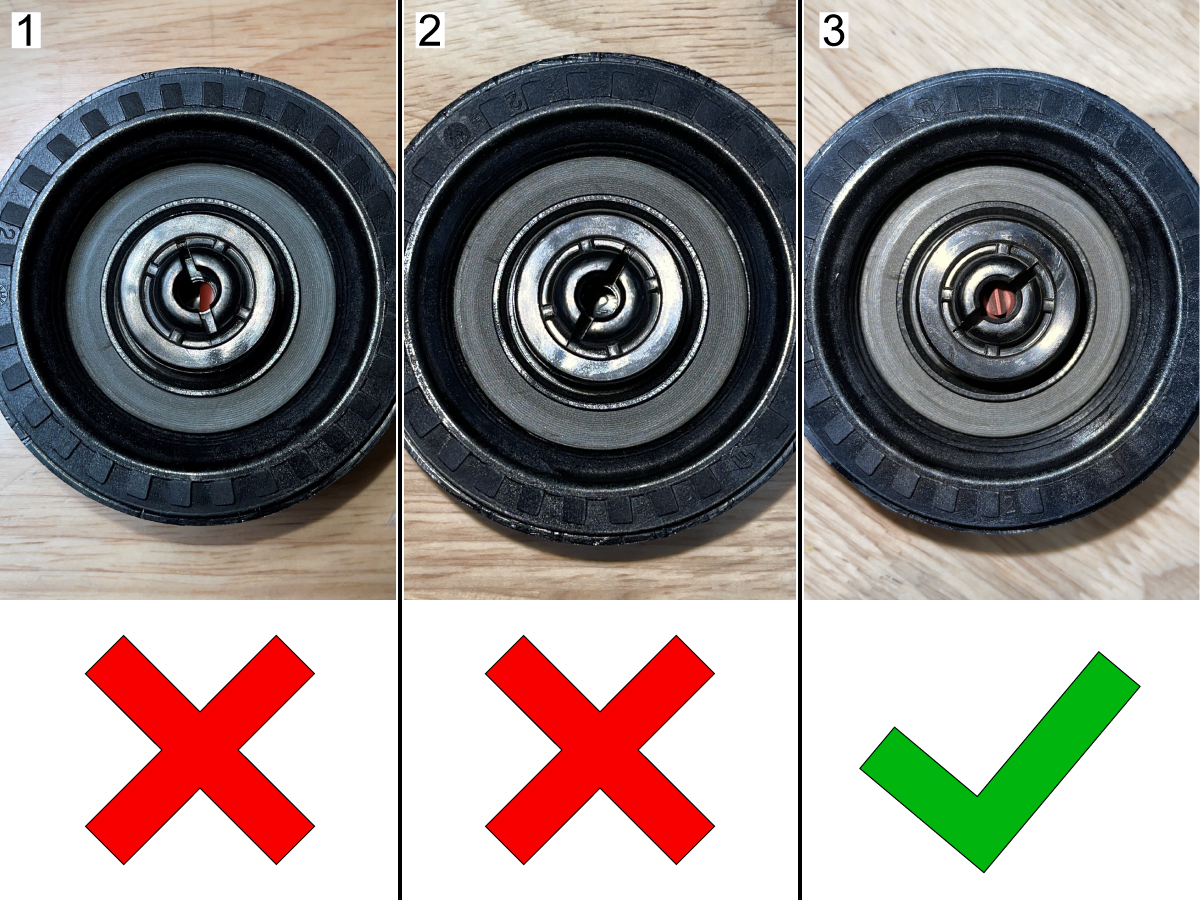
Reinstall Cap Seal

1

Remove the tank cap and check to see if the seal is in place. If it is out of position[1] or not visible[2], it will need to be reinstalled. Seal in the correct position[3].

2

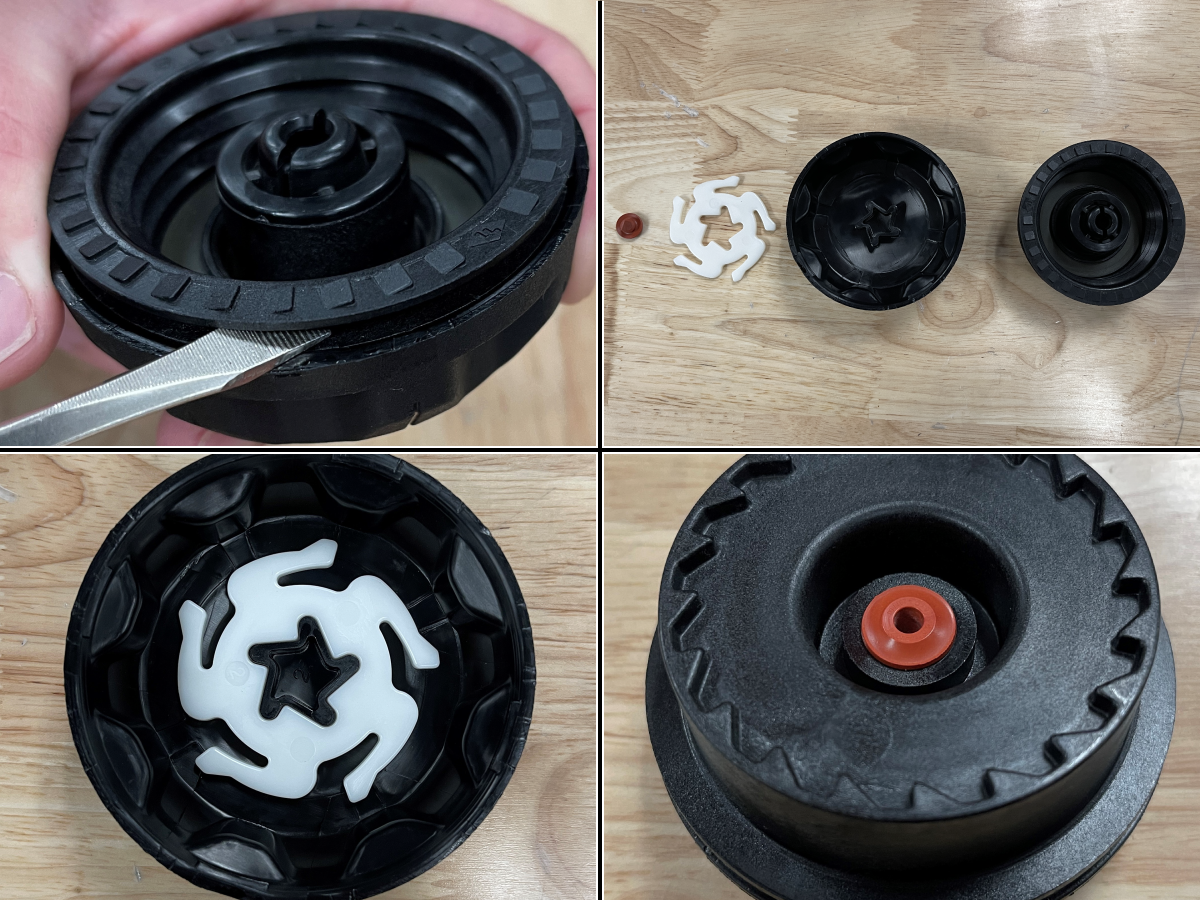
Remove the tank cap and check to see if the seal is in place. If it is out of position or not visible, it will need to be reinstalled.

Use a flathead screwdriver to separate the cap assembly. There are four clips that hold it together.

Remove the ratchet plate and the cap seal and thoroughly clean all the components.

Reinstall the ratchet plate. It can only be installed one way. Reinstall the cap seal.

Press both pieces together until the clips snap into place.

Reinstall the cap and verify the PulseJet works correctly.

Prime the Oil Line

Make sure there is oil in the PulseJet reservoir and that the lid is tightly installed. Make sure the reservoir air and oil lines are connected. 

Disconnect the oil line [1] from the PulseJet nozzle and let it drape over a container placed on the mill table.

Press [DIAGNOSTIC] and navigate to the Maintanance then to the PulseJet tab [2]. 

Press [F4] to begin a priming cycle. Each cycle lasts 10 minutes.  The reservoir will be pressurized during the cycle. 

Note: Small machines may take only 1 cycle to fully prime the line. Larger machines may take 3 or 4 cycles. Heavier oils may take longer to prime. Continue running priming cycles until oil [4] begins to drip out of the oil line into the container. 

Note: While the machine is in the prime cycle the user can start a program.   However the user will not be able to start the prime cycle again while the program is running.

Reconnect the oil line to the PulseJet nozzle.

In MDI run:

M162 P10;
G04 P10.;
M30;

Test the PulseJet until a strong stream develops. 

Tips and Troubleshooting

1.       PulseJet will produce a consistent, fast, and tight oil pulse if the line is well primed, the dispenser needle is not clogged, and a recommended oil is being used.

2.       To always keep the line well primed:

  • Place the reservoir assembly near or above the spindle elevation
  • never let the tank run completely dry

3.       If you suspect that the dispenser needle is clogged, replace it. To do this, unscrew the knurled nozzle cap from the nozzle and gently twist and pull the yellow base of the needle off of the nozzle.

Note: This will expose the small check valve spring, do not lose it. Firmly press the replacement needle onto the nozzle taper. Re-install the nozzle cap finger tight.

4.       Use recommended oil: light viscosity oils and tapping or cutting fluids work the best. Heavy viscosity oils such as motor oil, gear oil, or heavy tapping oils may not produce a high-quality stream.

5.       If the oil line does get air bubbles inside, the pump inside the PulseJet nozzle will pass them through the system. While bubbles are moving through the nozzle, the stream will appear weak, aerated, and inconsistent. After the bubbles pass through, the stream will return to its proper form.

6.       Always make sure the reservoir cap is installed and tightened when running PulseJet to maintain the proper tank pressure.

PulseJet Lubrication

Refer to Lubricant Grease, and Sealant Table to see our recommended oil list.

PulseJet - Schematic

FIND DISTRIBUTOR
Feedback
Haas Logo

美元价格不包括关税、报关费用、保险费、增值税及运费。
USD prices DO NOT include customs duty, customs fees, insurance, VAT, or freight.

人民币价格包含关税、报关费用、货运保险和增值税, 但不包括运费。
CNY prices include customs duty, customs fees, insurance, and VAT. DOES NOT include freight.

Haas Delivered Price

This price includes shipping cost, export and import duties, insurance, and any other expenses incurred during shipping to a location in France agreed with you as a buyer. No other mandatory costs can be added to the delivery of a Haas CNC Product.

KEEP UP WITH THE LATEST HAAS TIPS AND TECHNOLOGY...

Sign up now!   

HAAS TOOLING ACCEPTS THE FOLLOWING:

  • Service & Support
  • Owners
  • Request Service
  • Operator Manuals
  • Haas Parts
  • Rotary Repair Request
  • Pre-Install Guides
  • Shopping Tools
  • Build & Price a New Haas
  • Available Inventory
  • The Haas Price List
  • CNCA Financing
  • About Haas
  • Careers
  • Certifications & Safety
  • Contact Us
  • History
  • Terms & Conditions
  • Haas Tooling Terms & Conditions
  • Privacy
  • Warranty
  • Haas Community
  • Haas Certification Program
  • Haas Motorsports
  • Gene Haas Foundation
  • Haas Technical Education Community
  • Events
  • Join the Conversation
  • Facebook
  • Twitter
  • Flickr
  • YouTube
  • LinkedIn
  • Instagram
  • TikTok
© 2022 Haas Automation, Inc – CNC Machine Tools

2800 Sturgis Rd., Oxnard, CA 93030 / Toll Free: 800-331-6746
Phone: 805-278-1800 / Fax: 805-278-2255

Cookie Notice

We use cookies to improve your user experience. Our Cookie Notice describes which cookies we use, why we use them, and how you can find more information about them. Please confirm you consent to us using analytics cookies. If you do not consent, you may still use our website with a reduced user experience.

Manage Settings

Cookie Notice

We use cookies to improve your user experience. Our Cookie Notice describes which cookies we use, why we use them, and how you can find more information about them. Please confirm you consent to us using analytics cookies. If you do not consent, you may still use our website with a reduced user experience.

Functional Cookies

Analytics Cookies