My Haas Welcome,
!
Haas Tooling MyHaas/HaasConnect Sign In Register Haas Tooling MyHaas/HaasConnect Sign Out Welcome, My Machines Latest Activity My Quotes My Account My Users Sign Out
Find Your Distributor
  1. Select Language
    1. English
    2. Deutsch
    3. Español - ES
    4. Español - MX
    5. Français
    6. Italiano
    7. Português
    8. Český
    9. Dansk
    10. Nederlands
    11. Magyar
    12. Polski
    13. Svenska
    14. Türkçe
    15. 中文
    16. Suomi
    17. Norsk
    18. الإنجليزية
    19. български
    20. Hrvatski
    21. Ελληνικά
    22. Română
    23. Slovenský
    24. Slovenščina
    25. 한국어
    26. 日本語
    27. Українська
  • machines Main Menu
    • Vertical Mills
      Vertical Mills
      Vertical Mills View All
      • Vertical Mills
      • VF Series
      • Universal Machines
      • VR Series
      • VP-5 Prismatic
      • Pallet-Changing VMCs
      • Mini Mills
      • Mold Machines
      • High-Speed Drill Centers
      • Drill/Tap/ Mill Series
      • Toolroom Mills
      • Pocket Mill
      • Compact Mills
      • Gantry Series
      • SR Sheet Routers
      • Extra-Large VMC
      • Double-Column Mills
      • 3+2 Positioning Machines
    • Multi-Axis Solutions
      Multi-Axis Solutions
      Multi-Axis Solutions View All
      • Multi-Axis Solutions
      • Y-Axis Lathes
      • 5-Axis Mills
    • Lathes
      Lathes
      Lathes View All
      • Lathes
      • ST Series
      • Dual-Spindle
      • Box Way Series
      • Toolroom Lathes
      • Chucker Lathe
      • Pocket Lathe
      • Haas Bar Feeders
    • Horizontal Mills
      Horizontal Mills
      Horizontal Mills View All
      • Horizontal Mills
      • 50-Taper
      • 40-Taper
    • Rotaries & Indexers
      Rotaries & Indexers
      Rotaries & Indexers View All
      • Rotaries & Indexers
      • Rotary Tables
      • Indexers
      • 5-Axis Rotaries
      • Extra-Large Rotaries
    • Special Series
      Special Series
      Special Series View All
      • Special Series
      • EU_Series_Redirect
    • Automation Systems
      Automation Systems
      Automation Systems View All
      • Automation Systems
      • Mill Automation
      • Lathe Automation
      • Automatic Parts Loaders
      • Automation Models
    • Desktop Machines
      Desktop Machines
      Desktop Machines View All
      • Desktop Machines
      • Desktop Mill
      • Desktop Lathe
      • Control Simulator, Standard
      • Control Simulator, Premium
    • Shop Equipment
      Shop Equipment
      Shop Equipment View All
      • Shop Equipment
      • Knee Mill
      • Haas Manual Lathes
      • Haas Saws
    • Fabrication Machines
      Fabrication Machines
      Fabrication Machines View All
      • Fabrication Machines
      • Laser Cutting Machines
      • CNC Press Brakes
    • QUICK LINKS Special Series  Special Series 
      EU SERIES EU SERIES BUILD & PRICE | PRICE LIST BUILD & PRICE | PRICE LIST In-Stock Machines In-Stock Machines WHAT’S NEW WHAT’S NEW YOUR FIRST CNC YOUR FIRST CNC
      SHOPPING TOOLS
      • Build & Price a Haas
      • Price List
      • Available Inventory
      • CNCA Financing
      WANT TO TALK TO SOMEONE?

      A Haas Factory Outlet (HFO) can answer your questions, and walk you through your best options.

      CONTACT YOUR DISTRIBUTOR >
  • Options Main Menu
    • The Haas Control Value Option Packages
      Value Option Packages
      Value Option Packages View All
      • Value Option Packages
    • Product Image Spindles
      Spindles
      Spindles View All
      • Spindles
    • Product Image Tool Changers
      Tool Changers
      Tool Changers View All
      • Tool Changers
    • Product Image 4th- | 5th-Axis
      4th- | 5th-Axis
      4th- | 5th-Axis View All
      • 4th- | 5th-Axis
    • Product Image Turrets & Live Tooling
      Turrets & Live Tooling
      Turrets & Live Tooling View All
      • Turrets & Live Tooling
    • Product Image Probing
      Probing
      Probing View All
      • Probing
    • Haas Chip & Coolant Management Chip & Coolant Management
      Chip & Coolant Management
      Chip & Coolant Management View All
      • Chip & Coolant Management
    • The Haas Control The Haas Control
      The Haas Control
      The Haas Control View All
      • The Haas Control
    • Product Image Product Options
      Product Options
      Product Options View All
      • Product Options
    • Product Image Tooling & Fixturing
      Tooling & Fixturing
      Tooling & Fixturing View All
      • Tooling & Fixturing
    • Product Image Workholding
      Workholding
      Workholding View All
      • Workholding
    • Product Image 5-Axis Solutions
      5-Axis Solutions
      5-Axis Solutions View All
      • 5-Axis Solutions
      • 5 Easy Steps to 5-Axis
    • QUICK LINKS Special Series  Special Series 
      EU SERIES EU SERIES BUILD & PRICE | PRICE LIST BUILD & PRICE | PRICE LIST In-Stock Machines In-Stock Machines WHAT’S NEW WHAT’S NEW YOUR FIRST CNC YOUR FIRST CNC
      SHOPPING TOOLS
      • Build & Price a Haas
      • Price List
      • Available Inventory
      • CNCA Financing
      WANT TO TALK TO SOMEONE?

      A Haas Factory Outlet (HFO) can answer your questions, and walk you through your best options.

      CONTACT YOUR DISTRIBUTOR >
  • Why Haas Main Menu
      Discover the Haas Difference
    • Why Haas
    • MyHaas
    • Education Community
    • Industry 4.0
    • Haas Certification
    • Customer Testimonials
  • Service Main Menu
      Welcome to Haas Service
      SERVICE HOME Operator’s Manuals How-To Procedures Troubleshooting Guides Preventive Maintenance Haas Parts Haas Tooling Videos
  • Videos Main Menu
  • Main Menu
    • View All
    • View All
    • View All
    • View All
      • HTEC Curriculum Support
      • Haas Value Option Packages (VOP) Journey
    • View All
      • Haas 10 kg Cobot Package
      • Cobot Kits
      • DC-1 Drill Center
      • CNC Sales News
      • Do More With Your Haas
    • View All
    • View All
      • contact-us-test
      • 4 - AUTOMATION SYSTEMS
      • Carousel-V2
      • expert test
      • Demo_Day_Trident-test
      • Link Test
      • image-sale-tag-test
      • article-list-test
      • Haas 25 kg Robot Package
      • test-algolia-page
    • View All
    • View All
    • View All
    • View All
      • calc-test
    • View All
    • QUICK LINKS Special Series  Special Series 
      EU SERIES EU SERIES BUILD & PRICE | PRICE LIST BUILD & PRICE | PRICE LIST In-Stock Machines In-Stock Machines WHAT’S NEW WHAT’S NEW YOUR FIRST CNC YOUR FIRST CNC
      SHOPPING TOOLS
      • Build & Price a Haas
      • Price List
      • Available Inventory
      • CNCA Financing
      WANT TO TALK TO SOMEONE?

      A Haas Factory Outlet (HFO) can answer your questions, and walk you through your best options.

      CONTACT YOUR DISTRIBUTOR >
  • Haas Tooling Main Menu
  • Haas Service Parts Main Menu

My Haas Welcome,
!
Haas Tooling MyHaas/HaasConnect Sign In Register Haas Tooling MyHaas/HaasConnect Sign Out Welcome, My Machines Latest Activity My Quotes My Account My Users Sign Out
Find Your Distributor
  1. Select Language
    1. English
    2. Deutsch
    3. Español - ES
    4. Español - MX
    5. Français
    6. Italiano
    7. Português
    8. Český
    9. Dansk
    10. Nederlands
    11. Magyar
    12. Polski
    13. Svenska
    14. Türkçe
    15. 中文
    16. Suomi
    17. Norsk
    18. الإنجليزية
    19. български
    20. Hrvatski
    21. Ελληνικά
    22. Română
    23. Slovenský
    24. Slovenščina
    25. 한국어
    26. 日本語
    27. Українська
×

Search Results

Web Pages

Images

    • <
    • 1
    • >

TL - 1/2 - TT - 4 Turret - Installation - AD0157

Service Home How To Procedures TL-1/2 - TT-4 - Turret - Installation

TL-1/2 - TT-4 - Turret - Installation

- Jump to Section - 1. Introduction 2. Installation (6 steps) 3. Parameter Setup - Parameter List (3 steps) 4. Parameter Setup - Parameters 128 and 212 (4 steps) 5. Alignment (6 steps) 6. Verification (1 step) Back to Top
Recently Updated Last updated: 11/10/2025

TL-1/2 - TT-4 - Turret - Installation


AD0157

Revision A - 5/2025

Introduction

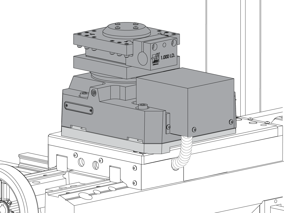
This procedure tells you how to install a TT-4 turret. 

Machine Compatibility:

  • Machine with Classic Haas Control
  • TL-1 with a serial number between 68200 (September 2004) and 3101284 (December 2014)
  • TL-2 with a serial number between 68221 (April 2005) and 3101296 (December 2014)

Prerequisites:

For Sigma 1 Field Installation Kits:

  • Lathe Software 7.04X or higher.

For Sigma 5 Field Installation Kits:

  • Lathe Software version 9.05 or higher.

 NOTE: If your machine has Lathe software version 9.04 or lower, you will need to order 93-3807 and 93-3808. These kits allows to run a Sigma 5 motor on an older software version. Refer to Sigma 1 to 5 Conversion - Installation - AD0681 procedure for more information. 

Sigma 1 Field Installation Kit:

TL-1 TT4: 

  • 93-10026 TT4, FIELD INSTALL INCH, TL1
  • 93-10028 TT4, TT4M, FIELD INSTALL METRIC, TL-1

TL-2 TT4:

  • 93-TT4-TL2-IN TT4, FIELD INSTALL INCH, TL2
  • 93-10027 TT4M, FIELD INSTALL METRIC, TL-2

Sigma 5 Field Installation Kit:

TL-1 TT4:

  • 93-1000972 TT4 SIG1-5 CONVERSION KIT INCH TL-1
  • 93-1000973 TT4 SIG1-5 CONVERSION KIT METRIC TL-1

TL-2 TT4:

  • 93-1000974 TT4 SIG1-5 CONVERSION KIT INCH TL-2
  • 93-1000975 TT4 SIG1-5 CONVERSION KIT METRIC TL-2

Tools Required:

  • Mylar Shims
  • 0.0005" dial indicator
  • P/N T-1312 ALIGNMENT BAR A2-6 SPNDL

Installation

1

Push [POWER OFF].

Open the control cabinet.

Set the main circuit breaker to the OFF position. Lock the main circuit breaker. Use an approved lock with an approved safety tag.

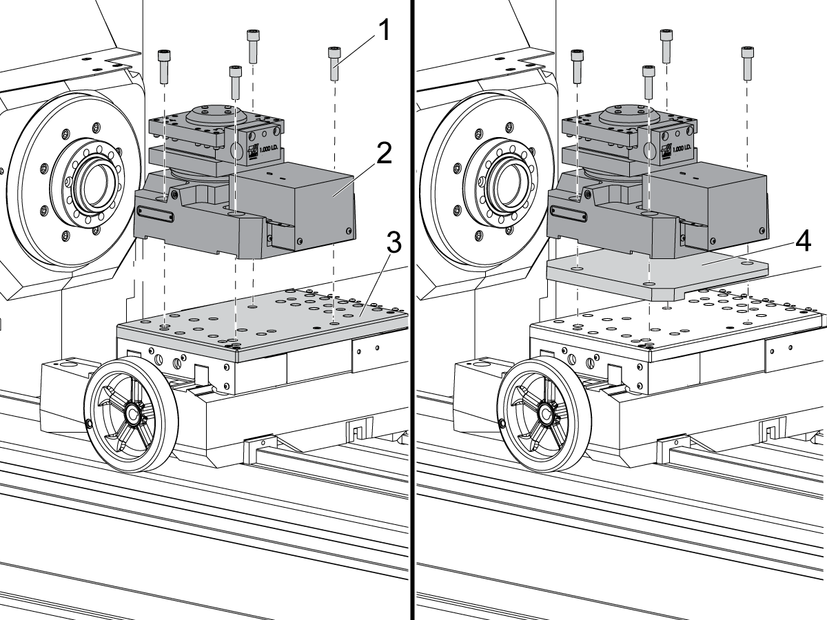
Clean the surface of the cross slide [3]. For a TL-1, put the turret [2] onto the cross slide [3]. For a TL-2, put the riser plate [4] onto the cross slide [3]. Keep the screws [1] sufficiently loose for turret alignment.

2

If the machine has a tool-changer air-pressure regulator, go to Step 3.

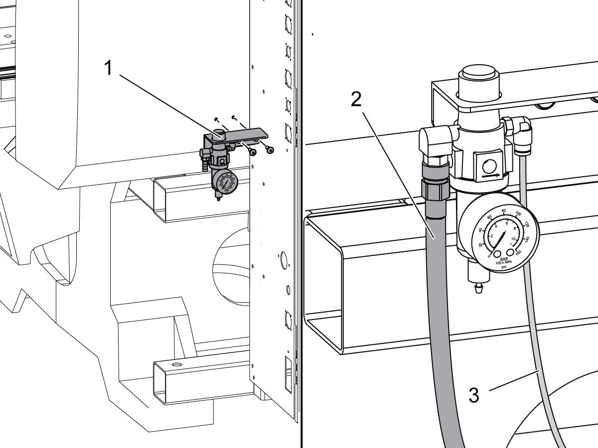
Find the pemnuts on the rear of the machine and left of the control cabinet. Install the included regulator [1] to the pemnuts.

Close the primary air valve. Connect the shop air hose [2] to the regulator input. Connect 11' (3 m) of 1/4" (6 mm) air tube [3] to the regulator output. Pull the air tube [3] through the bottom of the control cabinet.

3

 Danger: If the vector voltage indicator light is on, do not touch the electrical components. The high voltage in the control cabinet can kill you. Wait for the vector voltage indicator LED to go off fully.

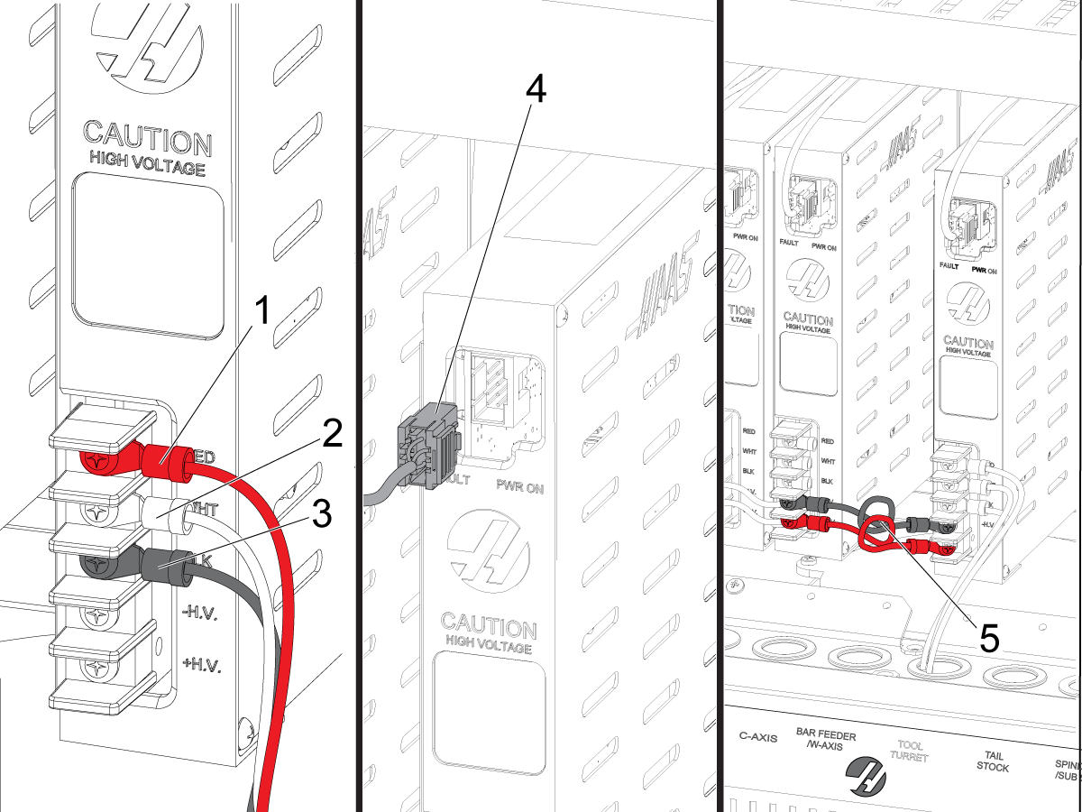
Put the 30-Amp servo amplifier into the amplifier bank section that has the label "Tool Turret".

Connect the power wires to the high voltage terminals on the amplifier:

  • red to RED [1]
  • white to WHT [2]
  • black to BLK [3]

Connect the current command cable [4] to the connector at the top of the amplifier.

Install the jumpers [5] from the nearest amplifier to the 30-Amp servo-amplifier:

  • Connect the black wire to -H.V.
  • Connect the red wire to +H.V.

4

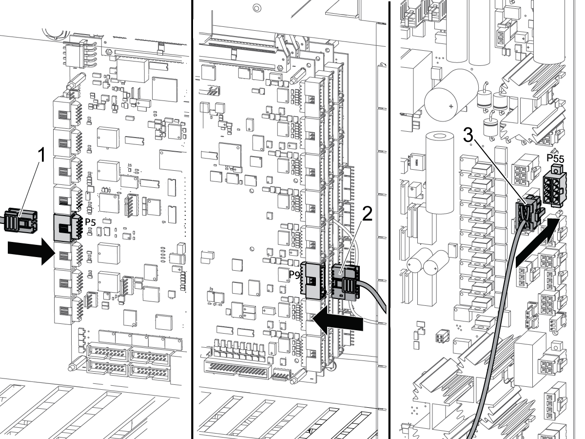
Connect the current command cable [1] from the amplifier to P5 on the Mocon PCB.

Find the encoder cable [2] for the turret motor. Connect the encoder cable to P9 on the Mocon PCB.

 Note: On some machines, the position of the PCBs is different than the illustration.

Pull the encoder cable [2] through the bottom of the control cabinet.

Connect the air solenoid cable [3] to P55 on the I/O board. Put the other end of the air solenoid cable [3] to the bottom of the control cabinet.

5

Put these cables through the bottom opening of the control cabinet:

  • Air Hose running from the regulator
  • Air Solenoid Cable
  • Home Switch Cable
  • Turret Power Cable
  • Turret Encoder Cable

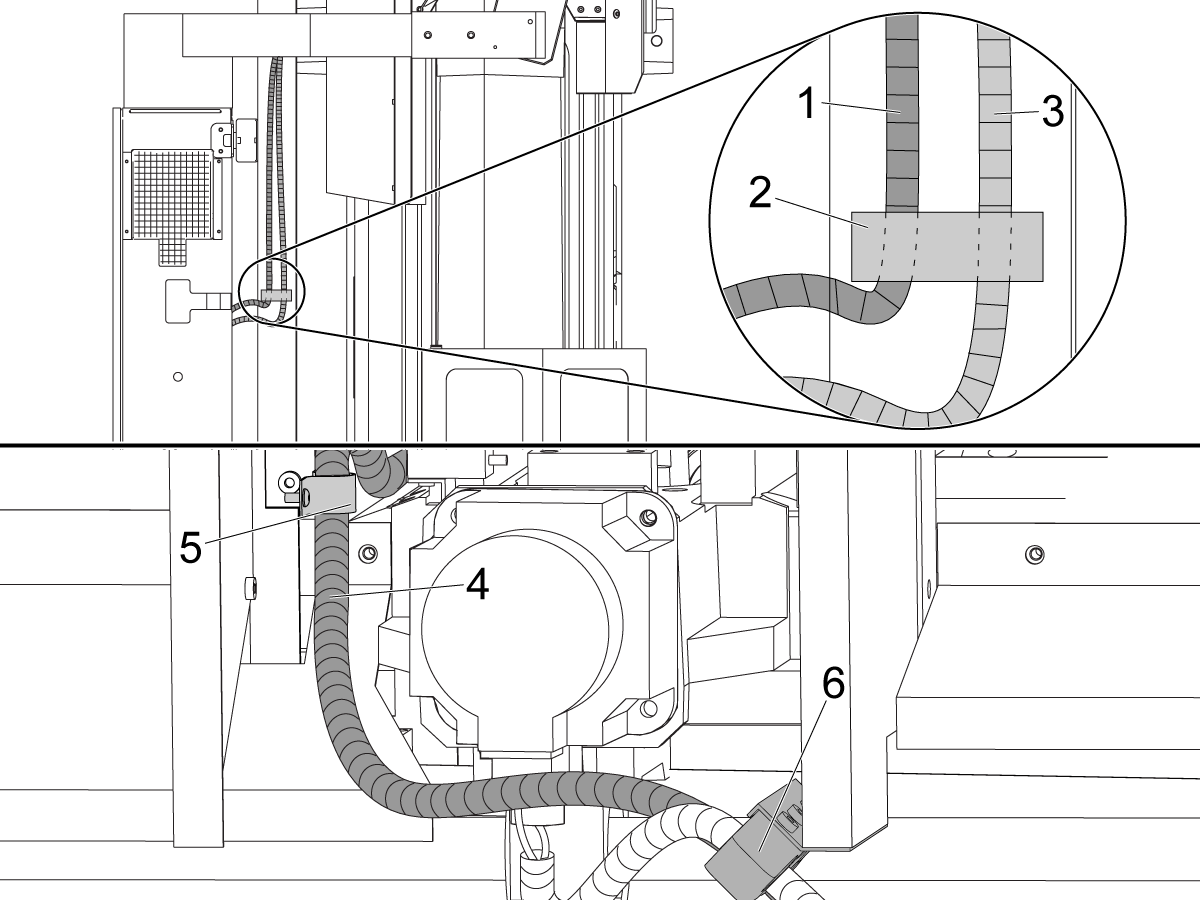
Put the cables through the split flex conduit bracket and into the conduit [1].

Put the conduit over the control mount base. Put it adjacent to the X-axis motor cable conduit [3]. Attach each conduit to the control mount base. Use the clamp block [2].

Put the conduit [4] to the rear of the cross slide. Put the conduit correctly in the clamp block [6]. Put the conduit correctly in cable clamp [5].

6

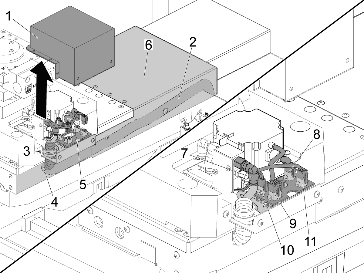
Remove the cover [1] for the turret servo-motor. Remove the cross-slide waycover [6].

Pull the conduit [2] along the tray at the bottom of the cross-slide cable channel. Pull the conduit [2] through the opening [4] on the front of the cross-slide. Put the conduit through the cable clamp [3] on the motor assembly.

Connect the electrical cables to the bracket [5]. Connect the air hose to the air fitting [7]. Connect the power cable [8], motor encoder cable [9], TC solenoid cable [10], and the home switch cable [11].

Put all of the connectors under the motor cover [1]. Coolant can cause damage to the connectors if you put them in the lower cross-slide channel.

Install the cover for the turret motor.

Set the main circuit breaker to the ON position.

Start the air supply to the machine. Set the tool-changer air-regulator pressure to 80 psi (5.5 bar). Open the primary air valve.

Push [POWER ON].

Parameter Setup - Parameter List

1

Make sure these parameters have these values:

 Note: Set Setting 7, Parameter Lock, to OFF.

Parameter Name Sigma 1 Value
44 A P GAIN 16
45A A D GAIN 8000
46 A I GAIN 32
47 A RATIO (Steps/Units) 8192
48 A MAX TRAVEL (Steps) 0
49 A ACCELERATION 150000
50 A MAX SPEED 20000
51 A MAX ERROR 4096
52 A FUSE LEVEL 238000
53 A BACK EMF 0
54 A STEPS/REVOLUTION 8192
57, bit 1 DISABLE TOOL CHANGR 0
60 TURRET IN POST DELAY TT-4 250
61 TURRET LOCK DELAY TT-4 250
62 TURRET UNLK ERRTIME TT-4 700
63 TURRET LOCK ERRTIME TT-4 250
65 NUMBER OF TOOLS 4
104 A IN POSITION LIMIT 8000
108 A MAX CURRENT 1297
112 A D*D GAIN 4000
116 A ACC/DEL T CONST 750
137 A EXACT STOP DIST 64
148 A ACCEL FEED FORWARD 125000
710 TOOL CHANGER TYPE TT-4 4

2

Set the bits for Parameter 43 to these values:

Bit Name Sigma 1 Value
3 DISABLED 0
10 CIRC. WRAP 1
11 NO I IN BRAK 1
12 LOW PASS +1X 1
13 LOW PASS +2X 1
22 D FILTER X8 0
23 D FILTER X4 0
25 A 3 EREV/MREV 1
29 ROTARY AXIS 1

3

Set Setting 97 (Tool Change Direction) to "Shortest".

Set Setting 113 (Tool Change Method) to "Auto".

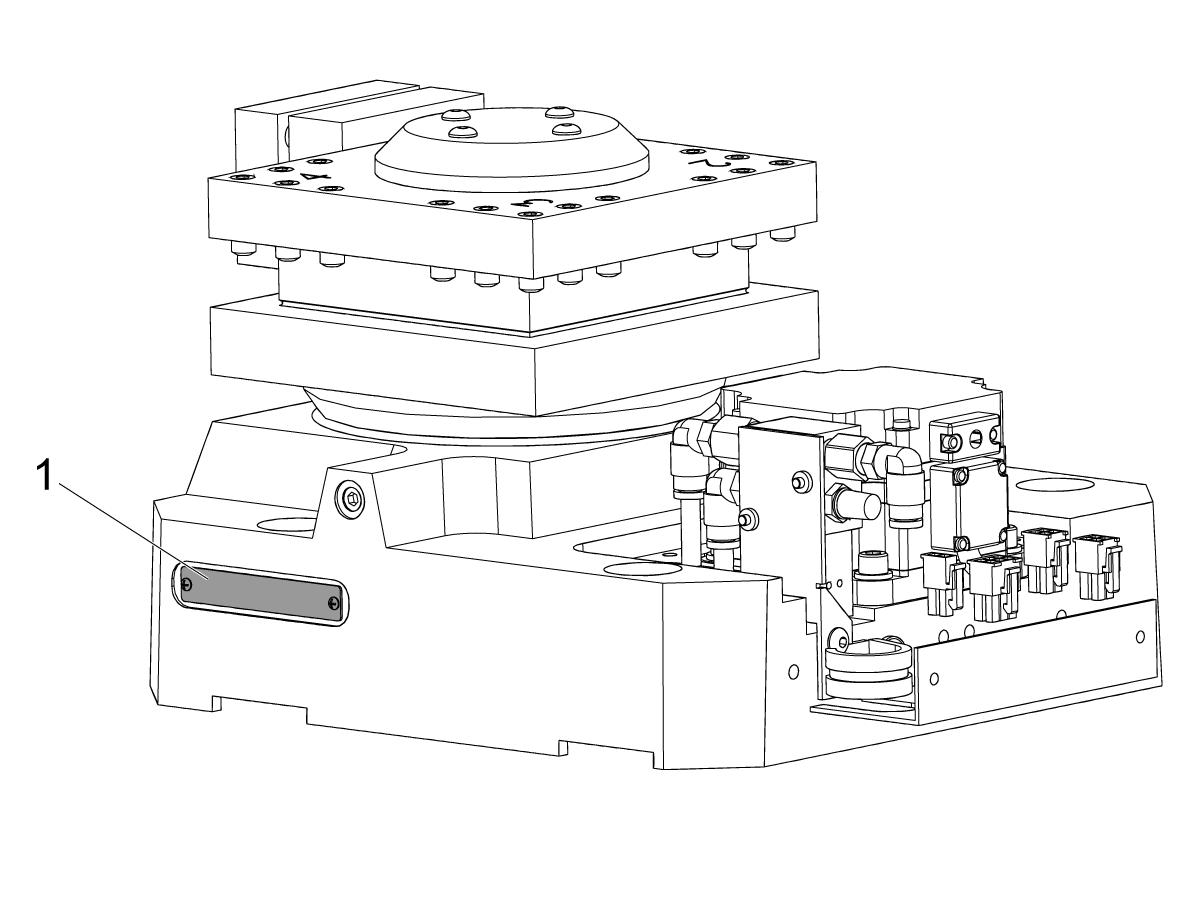
Look at the TT-4 identification plate [1].

 Note: Turrets made after December 2014 have the values for Parameters 128 and 212 on the identification plate.

If the parameter values are not on the identification plate. Go to the next section ("Parameter Setup - Parameters 128 and 212").

If the values are on the identification plate:

  • Set Parameters 128 and 212 to the values on the identification plate.
  • Set Setting 7 (Parameter Lock) to ON.
  • Do not do section ("Parameter Setup - Parameters 128 and 212").

Parameter Setup - Parameters 128 and 212

1

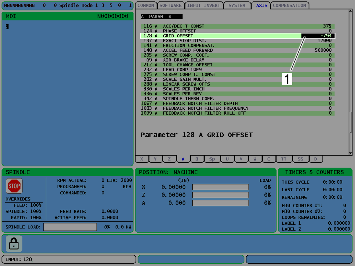
Set the A-Axis Grid Offset. Do these steps:

Set Setting 7, Parameter Lock, to OFF.

Set Parameters 128 and 212 to values of 0.

Push [RESET] to stop each alarm. Go into DEBUG mode.

Push [ZERO RETURN]. Push [A]. Push [SINGLE].

 Note: Ignore the ZERO RETURN MARGIN TOO SMALL alarm.

Type GRID A on the Raw Data Screen.

Make sure that Parameter 128 has a value [1].

If Parameter 128 does not have a value, do this step again.

2

Set the Tool Change Offset, as follows:

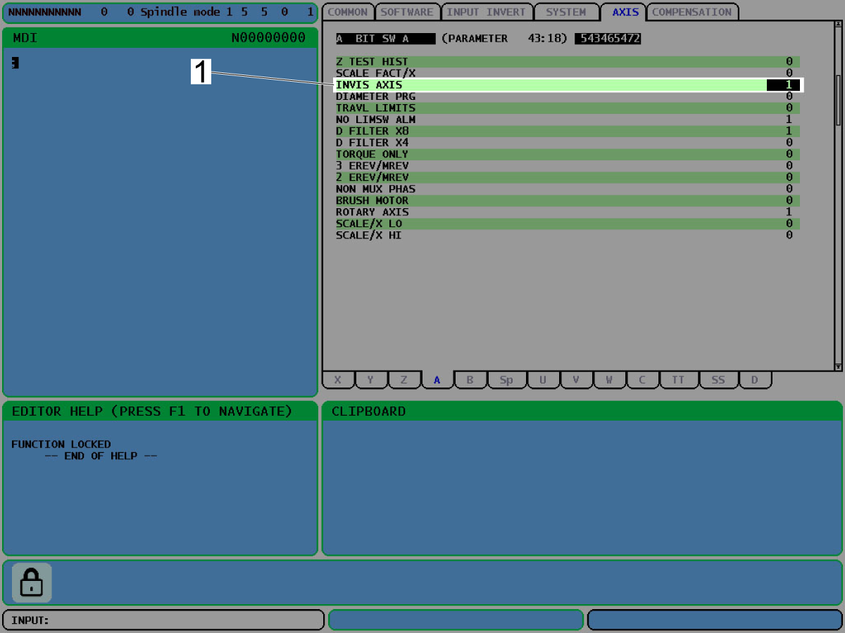
Set Parameter 43 bit 18 (Invis Axis) to zero.

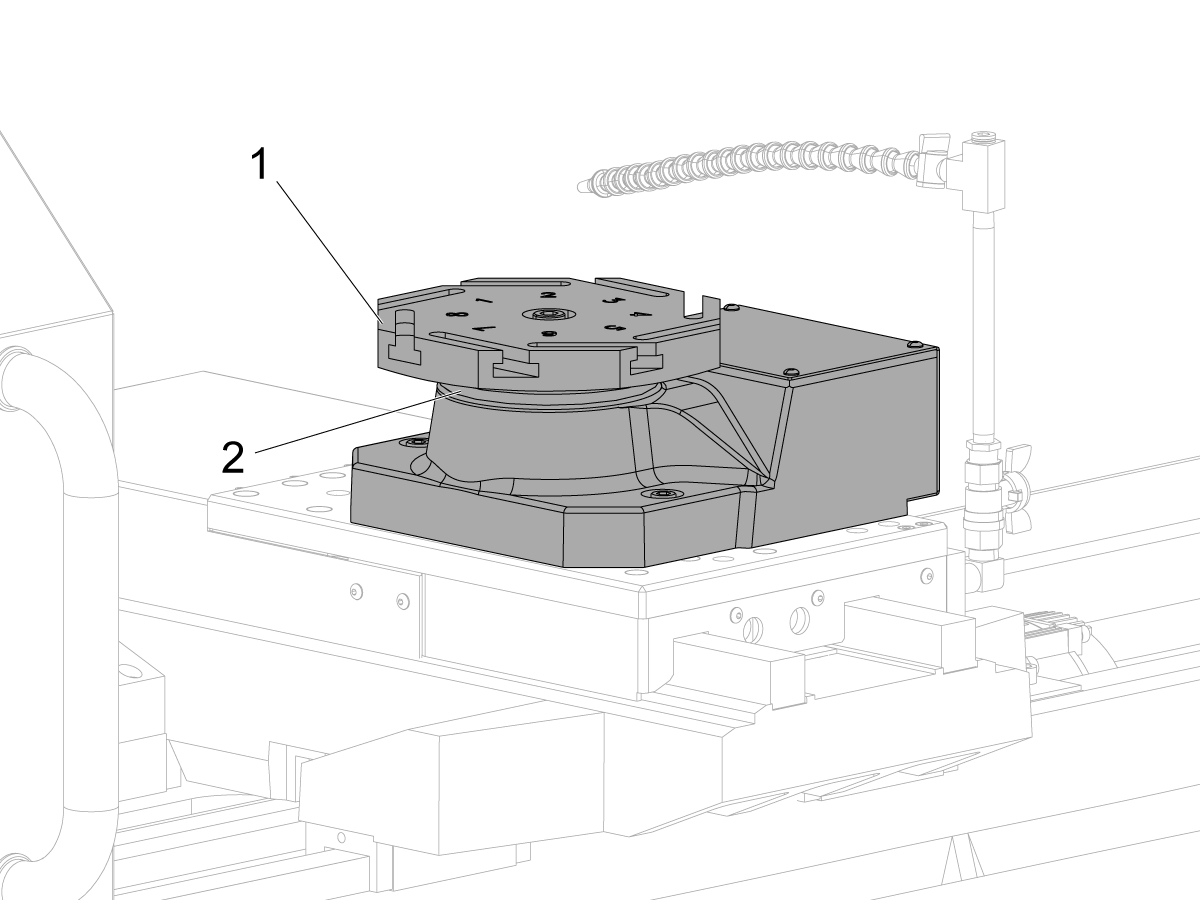
Go into [MDI] mode. Set the turret to tool 1 (T1). Use M43 to unclamp (disengage) the turret.

Push [EMERGENCY STOP] when the tool turret [1] is in the unclamped (disengaged) position [2].

Manually move the turret to tool 1.

Release [EMERGENCY STOP].

Push [RESET].

Use M44 to clamp the turret.

Make sure turret clamps (engages) fully. If the turret does not clamp fully, do this step again.

3

Push [EMERGENCY STOP].

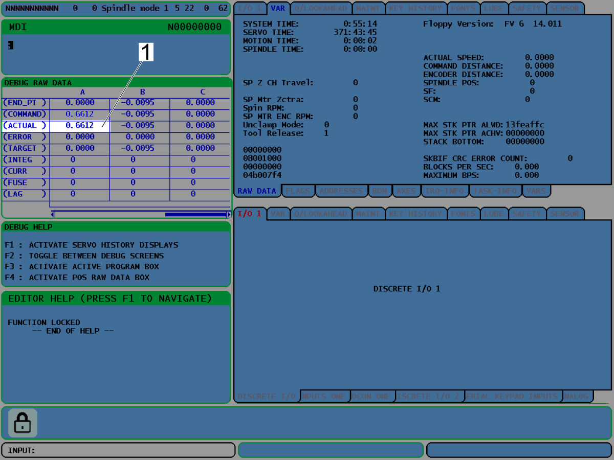
Go to the POS-RAW-DATA screen.

Record the ACTUAL A-Axis position [1].

 Note: In this example the ACTUAL A-Axis position is 0.6612.

Go to Parameter 212.

Type the opposite value of the ACTUAL A-Axis position [1].

 Note: For example the ACTUAL A-Axis position 0.6612 becomes -0.6612.

Make sure the turret clamps correctly.

If the turret does not correctly clamp, do steps 2 and 3 again.

4

Go out of DEBUG mode.

Push [ZERO RETURN]. Push [A]. Push [SINGLE].

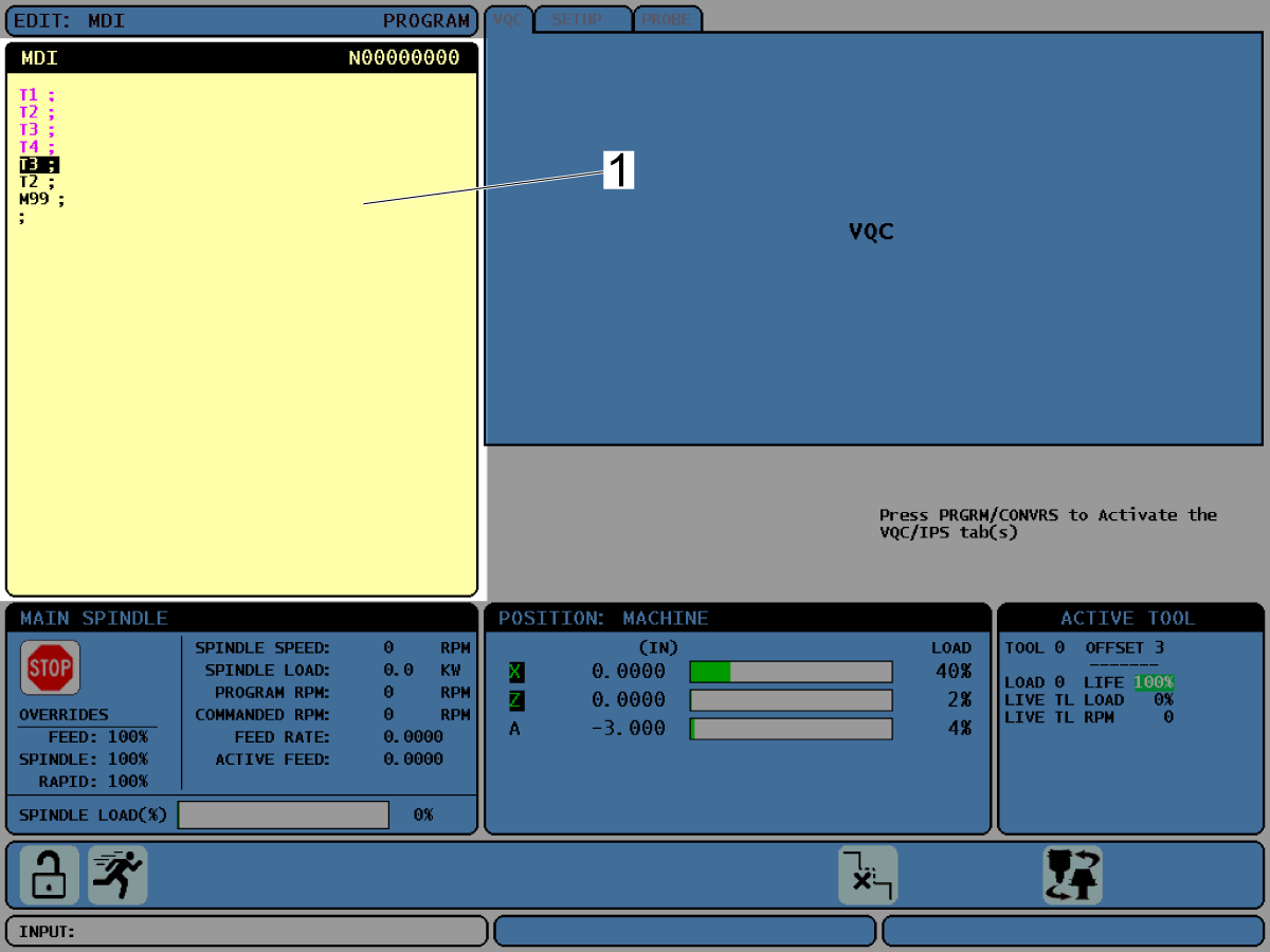
Make sure the tool changer operates correctly. Operate this code in [MDI] mode:

For TT-4 and ATT-4:

T1; T2; T3; T4; T3; T2; M99;

For ATT-8:

T1; T2; T3; T4; T5; T6; T7; T8; T7; T6; T5; T4; T3; T2; M99;

Set Parameter 43 bit 18 [1] to 1.

Set Setting 7, Parameter Lock, to ON.

Alignment

1

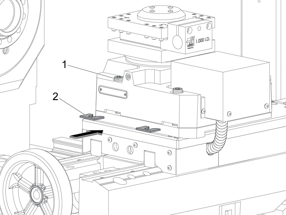
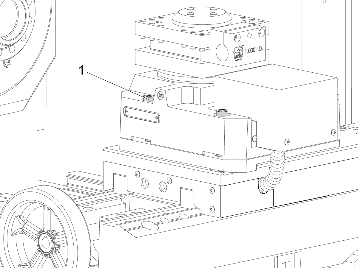
Install the (4) metal shims [2].

 Note: Be prepared to grind the shims to the correct thickness when you align the turret.

Do not tighten the turret mounting screws [1] at this time.

2

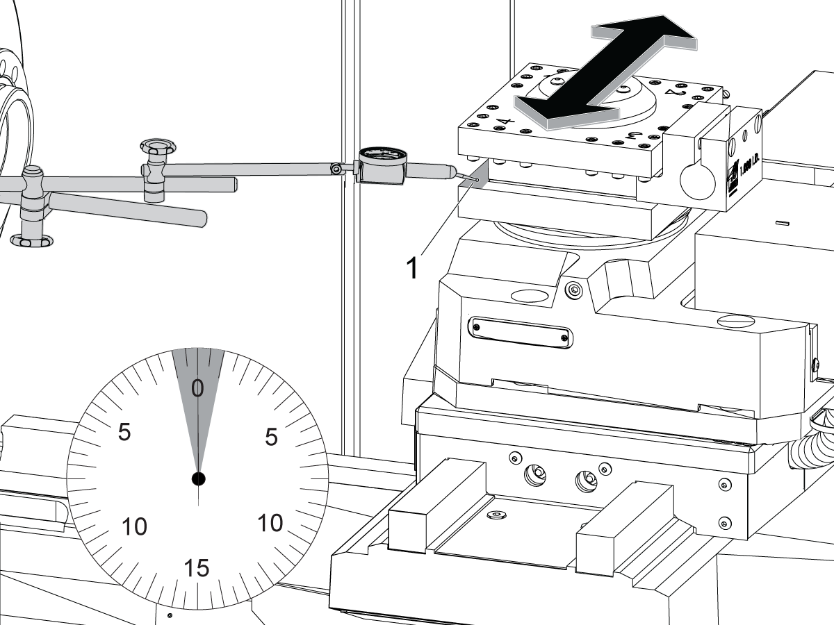
Make sure the tool turret is flat on the Z Axis. Do these steps:

Put a magnetic base indicator [1] on the spindle casting.

Put the tip of the indicator on the bottom inner surface [2] of the tool turret.

Put the indicator tip parallel to the Z Axis.

Jog the Z Axis.

Measure the alignment of the tool changer along the full surface.

The error cannot be more than 0.002" (0.05 mm) across 5.5" (140 mm) of travel.

Record the error.

3

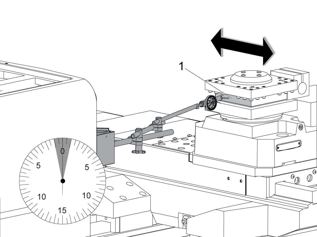
Make sure the tool turret is flat on the X Axis. Do these steps:

Put the tip of the indicator on the bottom inner surface [1] of the tool turret.

Put the indicator tip parallel to the X Axis.

Jog the X Axis.

Measure the alignment of the tool turret along the full surface.

Record your indicated values.

The error cannot be more than 0.002" (0.05 mm) across 5.5" (140 mm) of travel.

If the error is too large, do these steps:

  • To increase the height of the turret, add mylar shims.
  • Add mylar shims between the metal shims and turret.
  • To decrease the height of the turret, grind the metal shims.
  • Do steps 2 thru 3 again.

4

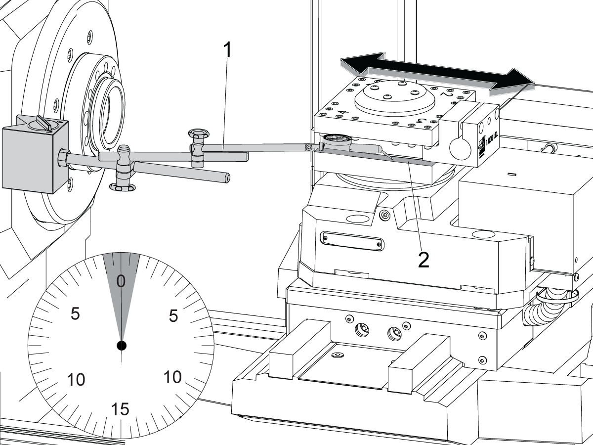
Make sure the tool turret is parallel with the X Axis. Do these steps:

Put the indicator tip against the inner vertical surface [1] of the tool turret.

Put the indicator tip parallel to the X Axis.

Jog the X Axis.

Measure the alignment of the tool changer along the full surface.

The error cannot be more than 0.001" (0.03 mm) across 5.5" (140 mm) of travel.

If the error is too large, make adjustments.

To make adjustments, lightly tap the base of the turret.

Use a soft mallet.

5

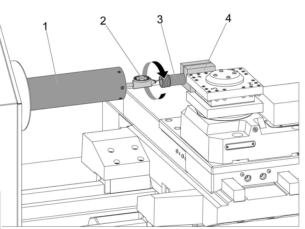
Make sure the tool turret aligns with the spindle centerline. Do these steps:

Install a toolholder [4] at tool position 1.

Put a 1" (25.4 mm) collet holder [3] in the toolholder.

Attach an indicator [2] to the center of a spindle alignment bar (P/N T-1312) [1].

Jog the X Axis to put the collet holder at the center of the spindle.

Manually turn the spindle 360 degrees.

This measures the error on the inner diameter of the collet holder.

The radial error cannot be more than 0.001" (0.0254 mm) around the circumference of the internal diameter.

If the error is too large, do these steps:

  • To increase the height of the turret, add mylar shims.
  • Add mylar shims between the metal shims and turret.
  • To decrease the height of the turret, grind the metal shims.
  • Do steps 2 thru 5 again.

6

Tighten the (4) 5/8" x 11 SHCS [1].

Tighten to the specified torque values.

 Note: Torque the screws. Refer to Haas Fastener Torque Specifications. Use the value for steel.

Do steps 2 thru 5 again to make sure the alignment is correct.

Verification

1

Make sure the tool changer operates corrrectly. Operate this code [1] in [MDI] mode:

T1; T2; T3; T4; T3; T2; M99;

Recently Viewed Items

You Have No Recently Viewed Items Yet

Feedback
Haas Logo

Haas Delivered Price

This price includes shipping cost, export and import duties, insurance, and any other expenses incurred during shipping to a location in France agreed with you as a buyer. No other mandatory costs can be added to the delivery of a Haas CNC Product.

KEEP UP WITH THE LATEST HAAS TIPS AND TECHNOLOGY...

Sign up now!   

HAAS TOOLING ACCEPTS THE FOLLOWING:

  • Service & Support
  • Owners
  • Request Service
  • Operator Manuals
  • Haas Parts
  • Rotary Repair Request
  • Pre-Install Guides
  • Shopping Tools
  • Build & Price a New Haas
  • Available Inventory
  • The Haas Price List
  • CNCA Financing
  • About Haas
  • Accessibility Statement
  • DNSH Statement
  • Export Compliance
  • Careers
  • Certifications & Safety
  • Contact Us
  • History
  • Terms & Conditions
  • Haas Tooling Terms & Conditions
  • Privacy
  • Warranty
  • Haas Community
  • Haas Certification Program
  • Haas Motorsports
  • Gene Haas Foundation
  • Haas Technical Education Community
  • Events
  • Join the Conversation
  • Facebook
  • X
  • Flickr
  • YouTube
  • LinkedIn
  • Instagram
  • TikTok
© 2026 Haas Automation, Inc – CNC Machine Tools
This site is protected by reCAPTCHA and the Google Privacy Policy and Terms of Service apply.

2800 Sturgis Rd., Oxnard, CA 93030
Toll Free: (888) 817-4446 / Fax: 805-278-8554