MyHaas Welcome,
!
Haas Tooling Guest Order History MyHaas/HaasConnect Sign In Register Haas Tooling My Account Order History Return History MyHaas/HaasConnect Sign Out Welcome, My Machines Latest Activity My Quotes My Account My Users Sign Out
Find Your Distributor
  1. Select Language
    1. English
    2. Deutsch
    3. Español - España
    4. Español - México
    5. Français
    6. Italiano
    7. Português
    8. Český
    9. Dansk
    10. Nederlands
    11. Magyar
    12. Polski
    13. Svenska
    14. Türkçe
    15. 中文
    16. Suomi
    17. Norsk
    18. الإنجليزية
    19. български
    20. Hrvatski
    21. Ελληνικά
    22. Română
    23. Slovenský
    24. Slovenščina
    25. 한국어
    26. 日本語
    27. Українська
  • machines Main Menu
    • Haas Vertical Mills Vertical Mills
      Vertical Mills
      Vertical Mills View All
      • Vertical Mills
      • VF Series
      • Universal Machines
      • VR Series
      • VP-5 Prismatic
      • Pallet-Changing VMCs
      • Mini Mills
      • Mold Machines
      • High-Speed Drill Centers
      • Drill/Tap/ Mill Series
      • Toolroom Mills
      • Compact Mills
      • Gantry Series
      • SR Sheet Routers
      • Extra-Large VMC
      • Double-Column Mills
      • Control Simulator
      • Mill Automatic Parts Loader
      • VMC/UMC Side-Loading Automatic Parts Loader
      • Compact Automatic Parts Loader
    • Product Image Multi-Axis Solutions
      Multi-Axis Solutions
      Multi-Axis Solutions View All
      • Multi-Axis Solutions
      • Y-Axis Lathes
      • 5-Axis Mills
    • Haas Lathes Lathes
      Lathes
      Lathes View All
      • Lathes
      • ST Series
      • Dual-Spindle
      • Box Way Series
      • Toolroom Lathes
      • Chucker Lathe
      • Haas Bar Feeder V2
      • Lathe Automatic Parts Loader
    • Haas Horizontal Mills Horizontal Mills
      Horizontal Mills
      Horizontal Mills View All
      • Horizontal Mills
      • 50-Taper
      • 40-Taper
    • Haas Rotaries & Indexers Rotaries & Indexers
      Rotaries & Indexers
      Rotaries & Indexers View All
      • Rotaries & Indexers
      • Rotary Tables
      • Indexers
      • 5-Axis Rotaries
      • Extra-Large Rotaries
    • Special Series
      Special Series
      Special Series View All
      • Special Series
      • EU_Series_Redirect
    • Product Image Automation Systems
      Automation Systems
      Automation Systems View All
      • Automation Systems
      • Mill Automation
      • Lathe Automation
      • Automation Models
    • Haas Drill Centers Desktop Machines
      Desktop Machines
      Desktop Machines View All
      • Desktop Machines
      • Desktop Mill
      • Desktop Lathe
    • Haas Shop Equipment Shop Equipment
      Shop Equipment
      Shop Equipment View All
      • Shop Equipment
      • Bandsaw
      • Knee Mill
      • Surface Grinder, 2550
      • Surface Grinder, 3063
      • Laser Cutting Machine
    • QUICK LINKS Special Series  Special Series 
      EU SERIES EU SERIES BUILD & PRICE | PRICE LIST BUILD & PRICE | PRICE LIST In-Stock Machines In-Stock Machines WHAT’S NEW WHAT’S NEW YOUR FIRST CNC YOUR FIRST CNC
      SHOPPING TOOLS
      • Build & Price a Haas
      • Price List
      • Available Inventory
      • CNCA Financing
      WANT TO TALK TO SOMEONE?

      A Haas Factory Outlet (HFO) can answer your questions, and walk you through your best options.

      CONTACT YOUR DISTRIBUTOR >
  • Options Main Menu
    • Product Image Spindles
      Spindles
      Spindles View All
      • Spindles
    • Product Image Tool Changers
      Tool Changers
      Tool Changers View All
      • Tool Changers
    • Product Image 4th- | 5th-Axis
      4th- | 5th-Axis
      4th- | 5th-Axis View All
      • 4th- | 5th-Axis
    • Product Image Turrets & Live Tooling
      Turrets & Live Tooling
      Turrets & Live Tooling View All
      • Turrets & Live Tooling
    • Product Image Probing
      Probing
      Probing View All
      • Probing
    • Haas Chip & Coolant Management Chip & Coolant Management
      Chip & Coolant Management
      Chip & Coolant Management View All
      • Chip & Coolant Management
    • The Haas Control The Haas Control
      The Haas Control
      The Haas Control View All
      • The Haas Control
    • Product Image Product Options
      Product Options
      Product Options View All
      • Product Options
    • Product Image Tooling & Fixturing
      Tooling & Fixturing
      Tooling & Fixturing View All
      • Tooling & Fixturing
    • Product Image Workholding
      Workholding
      Workholding View All
      • Workholding
    • Product Image 5-Axis Solutions
      5-Axis Solutions
      5-Axis Solutions View All
      • 5-Axis Solutions
      • 5 Easy Steps to 5-Axis
    • QUICK LINKS Special Series  Special Series 
      EU SERIES EU SERIES BUILD & PRICE | PRICE LIST BUILD & PRICE | PRICE LIST In-Stock Machines In-Stock Machines WHAT’S NEW WHAT’S NEW YOUR FIRST CNC YOUR FIRST CNC
      SHOPPING TOOLS
      • Build & Price a Haas
      • Price List
      • Available Inventory
      • CNCA Financing
      WANT TO TALK TO SOMEONE?

      A Haas Factory Outlet (HFO) can answer your questions, and walk you through your best options.

      CONTACT YOUR DISTRIBUTOR >
  • Why Haas Main Menu
      Discover the Haas Difference
    • Why Haas
    • MyHaas
    • Education Community
    • Industry 4.0
    • Haas Certification
    • Customer Testimonials
  • Service Main Menu
      Welcome to Haas Service
      SERVICE HOME Operator’s Manuals How-To Procedures Troubleshooting Guides Preventive Maintenance Haas Parts Haas Tooling Videos
  • Videos Main Menu
  • Main Menu
    • View All
    • View All
      • Fiber Laser
    • View All
    • View All
      • HTEC Curriculum Support
    • View All
      • Haas 10 kg Cobot Package
      • Cobot Kits
    • View All
    • View All
      • 4 - AUTOMATION SYSTEMS
      • Mill Toolholding
      • Carousel-V2
    • View All
    • View All
    • View All
      • VF-4SS
    • View All
    • QUICK LINKS Special Series  Special Series 
      EU SERIES EU SERIES BUILD & PRICE | PRICE LIST BUILD & PRICE | PRICE LIST In-Stock Machines In-Stock Machines WHAT’S NEW WHAT’S NEW YOUR FIRST CNC YOUR FIRST CNC
      SHOPPING TOOLS
      • Build & Price a Haas
      • Price List
      • Available Inventory
      • CNCA Financing
      WANT TO TALK TO SOMEONE?

      A Haas Factory Outlet (HFO) can answer your questions, and walk you through your best options.

      CONTACT YOUR DISTRIBUTOR >
  • Haas Tooling Main Menu
      Automation Accessories Shop Support Mill Toolholding Mill Cutting Tools Boring Systems Mill Workholding Lathe Toolholding Lathe Cutting Tools Lathe Workholding Package Kits ER Collets & Chucks Holemaking Threading Broaching Tombstones & Kits Manual Chucks For Milling Deburring & Abrasives Tool Presetter & Heat Shrinkers Storage & Handling Machine Maintenance Tooling Accessories Apparel & Accessories Measuring & Inspection Winner's Circle Winner's Circle Clearance Today's Hot Deals
    • Haas Tooling
    • Winner's Circle
      Winner's Circle Shop All
      • WINNERS_CIRCLE-1Y
    • Winner's Circle
      Winner's Circle Shop All
      • WC-1Y-EU
    • Today’s Hot Deals
      Today’s Hot Deals Shop All
      • Mill Toolholding
      • Mill Tooling
      • Measuring & Inspection
      • Boring Systems
      • Mill Workholding
      • Shell Mill Kits
      • Lathe Toolholding
      • Lathe Tooling
      • Lathe Workholding
      • ER Collets & Chucks
      • Holemaking
      • Threading
      • Broaching
      • Tool Storage
      • Apparel & Accessories
    • Clearance
      Clearance Shop All
    • Measuring & Inspection
      Measuring & Inspection Shop All
      • Probe Kits & Accessories
      • Edge & Center Finders
      • Comparative Measuring Gauges
      • Height Gauges
      • Calipers
      • Threaded Plug & Ring Gauges
      • Gauge Blocks
      • Pin Gauges
      • Drop Indicators
      • Dial Test Indicators
      • Bore Gauges
      • Indicator Accessories
      • V Blocks
      • Setup Blocks
      • Depth Measuring
      • Micrometers
      • Micrometer Accessories
      • Micrometer Kits
      • Bore Gauge Kits
      • Starter Kits
      • Indicator Kits
      • Caliper Kits
      • Toolholder Check Station
      • Height Setters
      • Coordinate Measuring Machines
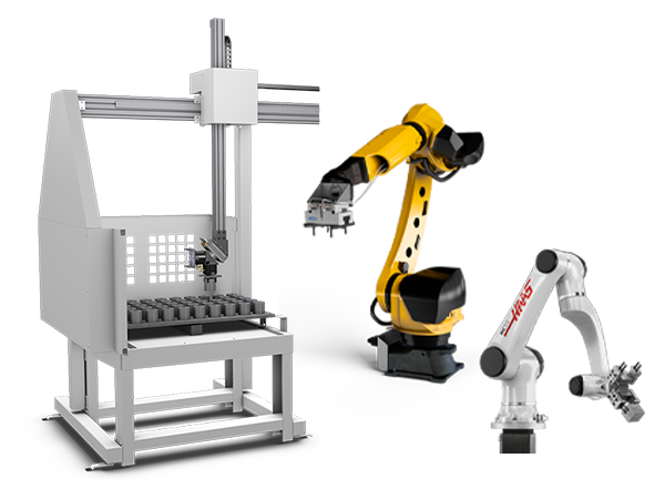
    • Automation Accessories
      Automation Accessories Shop All
      • Cobot Kits
      • Cobot Kits
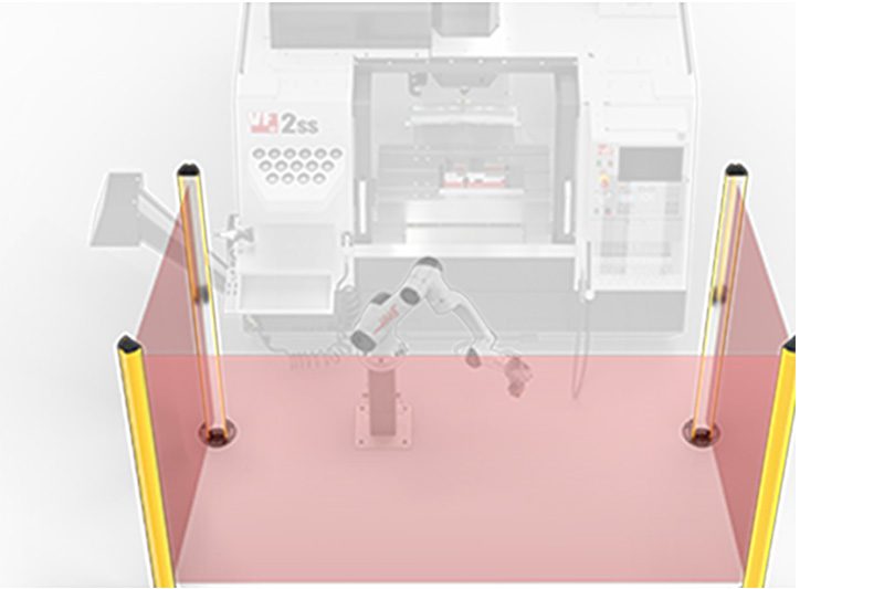
      • Protective Barriers
      • Grippers
      • Robot Cell Accessories
    • Shop Support
      Shop Support Shop All
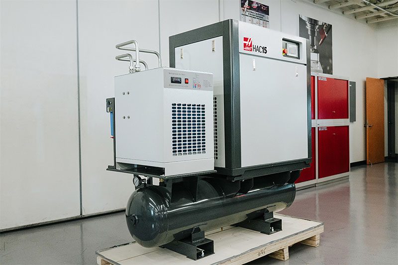
      • Air Compressors
      • Laser Marking Machines
      • Bandsaw Blades
      • Bandsaw Accessories
      • Surface Grinding Wheels
      • Shop Equipment Accessories
    • Mill Toolholding
      Mill Toolholding Shop All
      • End Mill Holders
      • Shell Mill Holders
      • Shrink Fit Holders
      • ER Collet Chucks
      • Milling Chucks & Collets
      • NC Drilling Chucks
      • Pull Studs / Retention Knobs
      • Rotary Tool Holder & Tool Chuck Kits
      • Hydraulic Milling Chucks & Collets
      • Toolholder Attachments & Wrenches
      • Mill Broaching Holders
    • Mill Tooling
      Mill Tooling Shop All
      • Shell Mill Bodies
      • Milling Inserts
      • End Mills
      • Chamfer Mills & Inserts
      • Indexable End Mill Bodies
      • Ball End Mills
      • Chamfer End Mills
      • Roughing End Mills
      • Indexable Ball End Mills & Inserts
      • Shell Mill Kits
      • Chamfer Mill Kits
      • Indexable End Mill Kits
      • Dovetail Cutters
      • Indexable Dovetail Cutters
      • Engraving End Mills
      • Rotary Burrs / Die Grinding Bits
      • Keyseat Cutters
      • Corner Rounding End Mills
      • Slot Mill Bodies
      • CNC Router Bits For Wood
    • Boring Systems
      Boring Systems Shop All
      • Boring Heads & Cartridges
      • Boring Holders & Extensions
    • Mill Workholding
      Mill Workholding Shop All
      • Fixed-Jaw Vises
      • Self-Centering Vises
      • Adapter Plates
      • Vise Jaws
      • Vise Mounts & Fixtures
      • Vise Kits
      • Vise Parallels
      • Rotary Vise Kits
      • Fixture Clamps & Rails
      • Automated Workholding Kits
      • Tooling Fixture Subplates
      • Toolmakers' Vises
      • Clamp Force Gauges
      • Collet Fixtures
      • Angle Plates
    • Lathe Toolholding
      Lathe Toolholding Shop All
      • TL & CL Static Turning Holders
      • BOT Static Turning Holders
      • BMT Static Turning Holders
      • Live / Driven Turning Holders
      • Turning Holder Reduction Sleeves / Bushings
      • VDI Static Turning Holders
      • Turning Holder Accessories
    • Lathe Tooling
      Lathe Tooling Shop All
      • Cut-Off Tool Blocks & Blades
      • Cut-Off Tooling Kits
      • Turning Inserts
      • Grooving & Cut-Off Tools
      • Internal (ID) Grooving & Threading Tools
      • Threading Inserts
      • Threading Tools
      • Boring Bars / Internal (ID) Turning Tools
      • External (OD) Turning Tools
      • Cermet Turning Inserts
      • CBN Turning Inserts
      • Haas Notch Grooving & Threading Inserts
      • Haas Notch Grooving & Threading Tools
      • Micro Turning Tools
      • Desktop Lathe Tools
    • Lathe Workholding
      Lathe Workholding Shop All
      • Live Centers
      • Spindle Reduction Sleeves / Liners
      • Quick-Change Collets
      • Quick-Change Collet Chucks
      • 5C Collets
      • 5C Collet Sets
      • Lathe Jaw Boring Rings
      • Lathe Jaws
      • Bar Pullers
      • Scroll Chucks
      • Guide Pins
      • Collet Accessories
    • Package Kits
      Package Kits Shop All
      • Chip Clearing Fan Kits
      • Cutting Tool Kits
      • Indexable End Mill Kits
      • Cut-Off Tool Block & Blade Kits
      • Drill & Tap Kits
      • Indexable Drilling Kits
      • Shell Mill Kits
      • Chamfer Mill Kits
      • Rotary Tool Holder & Tool Chuck Kits
      • Lathe Starter Kits
      • Workholding Kits
      • Rotary Vise Kits
      • Vise Kits
      • 3-Jaw Chuck Kits for Mills
      • Tombstone Kits
      • Reduction Sleeve Kits
      • Automated Workholding Kits
      • Measuring & Inspection Kits
      • Starter Kits
      • Bore Gauge Kits
      • Caliper Kits
      • Indicator Kits
      • Micrometer Kits
    • ER Collets & Chucks
      ER Collets & Chucks Shop All
      • ER Straight-Bore Collets
      • ER Sealed Collets
      • ER Tap Collets
      • ER Collet Sets & Accessories
      • ER Collet Chucks
      • Straight Shank ER Collet Chucks
      • Straight Shank Keyless NC Drilling Chucks
    • Holemaking
      Holemaking Shop All
      • Carbide Drills
      • Indexable Drill Bodies
      • Indexable Drill Inserts
      • Modular Drill Bodies
      • Modular Drill Heads
      • Cobalt Drills & Sets
      • Center Drills
      • Reamers
      • Indexable Drilling Kits
      • Spot Drills
      • Spade Drill Bodies
      • Spade Drill Inserts
      • Countersinks
    • Threading
      Threading Shop All
      • Taps
      • Threading Inserts
      • Threading Tools
      • Thread Mills
      • Pipe Taps
      • Drill Tap Kits
    • Broaching
      Broaching Shop All
      • Broaching Tools
      • Broaching Inserts
    • Tombstones
      Tombstones Shop All
      • Tombstones
      • Tombstone Kits
      • Vise Cluster Towers
    • Manual Chucks For Milling
      Manual Chucks For Milling Shop All
      • 3-Jaw Chucks & Mounts for Mills
    • Deburring & Abrasives
      Deburring & Abrasives Shop All

      • Abrasive Pads
      • Deburr Tools
      • Deburr Wheels
      • Abrasive Sheets & Rolls
      • Sharpening / Lapping Stones
    • Tool Presetter & Heat Shrinkers
      Tool Presetter & Heat Shrinkers Shop All
      • Tool Presetting Machines
      • Shrink Fit Machines
    • Tool Storage
      Tool Storage Shop All
      • Tool Carts
      • Tool Tray
      • Tool Bags
    • Machine Maintenance
      Machine Maintenance Shop All
      • Spindle Test Bars
      • Levels
      • Refractometers
      • Machine Additives & Supplies
      • Machine Accessories
      • Machine Maintenance Kits
    • Tooling Accessories
      Tooling Accessories Shop All
      • Spindle & Toolholder Taper Cleaners
      • Haas Shop Lift
      • Toolholder Fixtures
      • CNC Chip Clearing Fans
      • Hammers & Mallets
      • Anti-Fatigue Mats
      • Layout Tools
      • Wrenches
      • Magnetic Tools
      • Torque Screwdrivers
      • Hand Cutting Tools
      • Shop Stools
      • Lifting Magnets
      • Safety Apparel
      • Cutting Tool Sharpeners
    • Apparel & Accessories
      Apparel & Accessories Shop All
      • Accessories
      • Apparel
    • HAAS TOOLING QUICK LINKS
      NEW PRODUCTS NEW PRODUCTS NEW PRODUCTS NEW PRODUCTS
      MOST POPULAR MOST POPULAR
      TOOLING PROMOS TOOLING PROMOS
      FINANCING & OPEN TERMS FINANCING & OPEN TERMS PAY BY INVOICE PAY BY INVOICE
      FAQs FAQs
      KITS CREATED FOR YOU KITS CREATED FOR YOU
  • Haas Service Parts Main Menu
      Automatic Pallet Changer Lathe Turret Tool Changer Chip Management Coolant Counterbalance Electrical Cabinet Enclosure Hydraulics Lubrication Maintenance Pendant Probing Rotary Spindle Tailstock
    • Haas Service Parts
    • Automatic Pallet Changer
      Automatic Pallet Changer Shop All
      • HMC - Automatic Pallet Changer
      • VMC - Automatic Pallet Changer
    • Lathe Turret
      Lathe Turret Shop All
      • Lathe - Turret
      • Live Tooling
    • Tool Changer
      Tool Changer Shop All
      • Side Mount
      • Umbrella
    • Chip Management
      Chip Management Shop All
      • Multi Auger
      • Single Auger
    • Coolant
      Coolant Shop All
      • Auxiliary Filter
      • HPC-300 (Lathe)
      • HPC-1000 (Lathe)
      • Oil Skimmer
      • Standard Coolant
      • TSC-300 (Mill)
      • TSC-1000 (Mill)
      • Coolant Refill
      • Loc-Line
    • Counterbalance
      Counterbalance Shop All
      • Charge & Discharge Hose
    • Electrical Cabinet
      Electrical Cabinet Shop All
      • Fans
      • Filters
      • Upgrade Kits
    • Enclosure
      Enclosure Shop All
      • Accessories
      • Air Nozzle
      • Decals
      • Door Bumpers
      • Lighting
      • Windows, Gaskets, & Weather Strip
      • Chip & Coolant Management
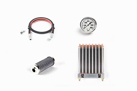
    • Hydraulics
      Hydraulics Shop All
      • Filters
      • Gauges
      • Heat Exchanger
      • Hoses
    • Lubrication
      Lubrication Shop All
      • Bijur Mechanical Lubrication
      • Minimum Lubrication
    • Maintenance
      Maintenance Shop All
      • Grease, Oil, & Sealants
    • Pendant
      Pendant Shop All
      • Floppy Disk & USB
      • Keypad
      • Keys
      • Lens
      • Gaskets & Seals
    • Probing
      Probing Shop All
      • Mill Probing
      • Lathe Tool Presetter
    • Rotary
      Rotary Shop All
      • Rotary Gaskets & Seals
    • Spindles
      Spindles Shop All
      • Couplings
      • Gaskets & Seals
      • Spindle Motor Drive
      • Gearbox Drive
      • Tool Release Piston
    • Tailstock
      Tailstock Shop All
      • Handles
×

Search Results

Web Pages

Images

    • <
    • 1
    • >
MyHaas Welcome,
!
Haas Tooling Guest Order History MyHaas/HaasConnect Sign In Register Haas Tooling My Account Order History Return History MyHaas/HaasConnect Sign Out Welcome, My Machines Latest Activity My Quotes My Account My Users Sign Out
Find Your Distributor
  1. Select Language
    1. English
    2. Deutsch
    3. Español - España
    4. Español - México
    5. Français
    6. Italiano
    7. Português
    8. Český
    9. Dansk
    10. Nederlands
    11. Magyar
    12. Polski
    13. Svenska
    14. Türkçe
    15. 中文
    16. Suomi
    17. Norsk
    18. الإنجليزية
    19. български
    20. Hrvatski
    21. Ελληνικά
    22. Română
    23. Slovenský
    24. Slovenščina
    25. 한국어
    26. 日本語
    27. Українська
×

Search Results

Web Pages

Images

    • <
    • 1
    • >

2 - Haas Axis Lubrication Oil

Lubrication Systems - Service Manual


  • 1 - Lube Systems - Introduction
  • 2 - Haas Axis Lubrication Oil
  • 3 - Haas Liquid Grease
  • 4 - Minimum Quantity Lubrication
  • 5 - PulseJet System

Go To :

  • 2.1 HALO - Axis Lubrication System
  • 2.2 HALO - Reservoir Refill
  • 2.3 HALO - Conversion
  • 2.4 Red Grease to HALO - Conversion
  • 2.5 HALO Metal Reservoir - Upgrade
  • 2.6 HALO - Troubleshooting

Introduction

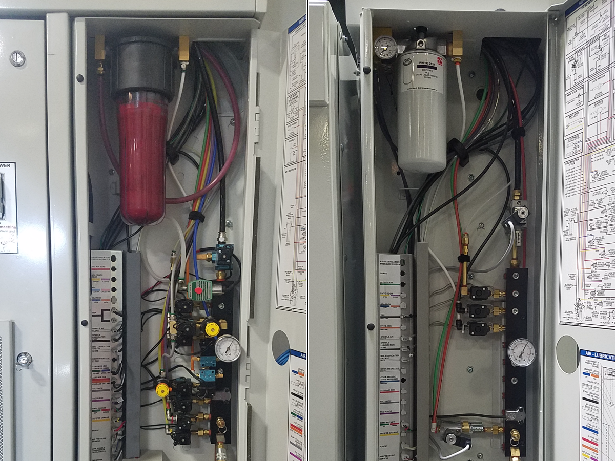
Note: The location of the oil reservoir is different on some machines.

The CALM - Haas Axis Lubrication Oil system is a restrictor oil flow system that pumps oil through flexible plastic tubing and copper tubes to the axes.


Identification

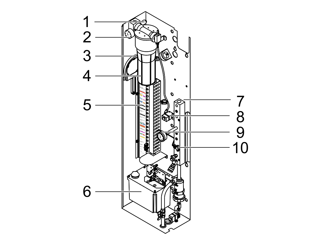
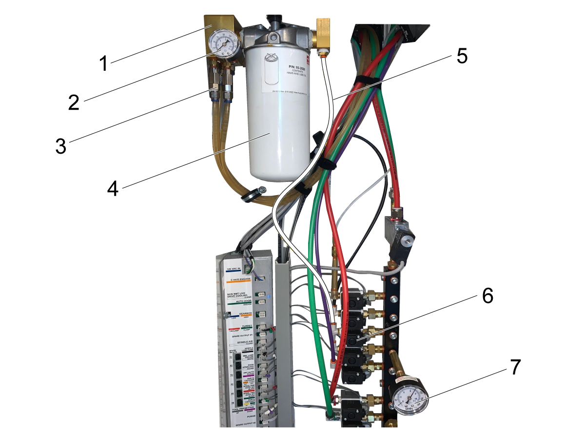
Use the illustration to identify the parts of the lubrication system.

Note: For recommended lubricant types, see Lubricant Table for Haas Machine Components.

  1. Oil Pressure Switch - Monitors the oil system pressure and sends a signal to the control to generate an alarm if the pressure drops below the minimum level too quickly.
  2. Oil Pressure Gauge - Shows the pressure (in psi and bar) of the oil system.
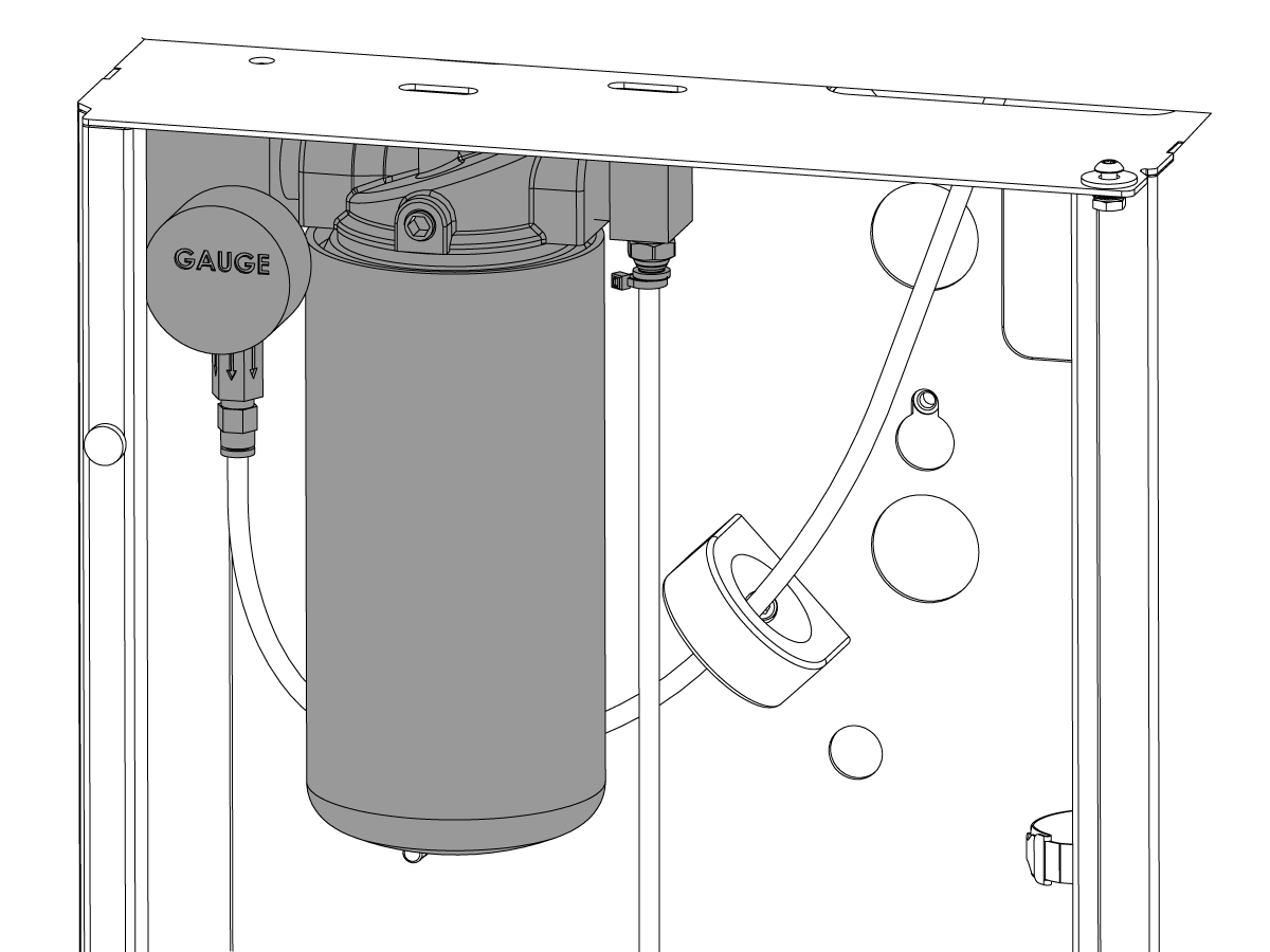
  3. Oil Filter Wrench - Removes the oil reservoir.
  4. Oil Reservoir Assembly - Stores the oil.
  5. Air-Lube Panel Decal - Shows the color-coded cables that connect each solenoid.
  6. Oil Reservoir - Stores the oil that lubricates the spindle.
  7. Air Manifold Assembly - Supplies air to the machine.
  8. Axis-Lube Air Solenoid - Pressurizes the oil reservoir.
  9. Air Pressure Gauge - Shows the pressure (in psi and bar) at which the air is supplied.
  10. Electronic Analog Air Pressure Sensor - Monitors the air system pressure and sends a signal to the control to generate an alarm if the pressure drops below the minimum level for a set period of time.

Axis Lubrication

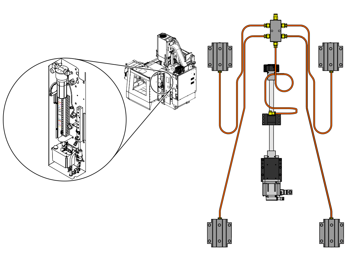
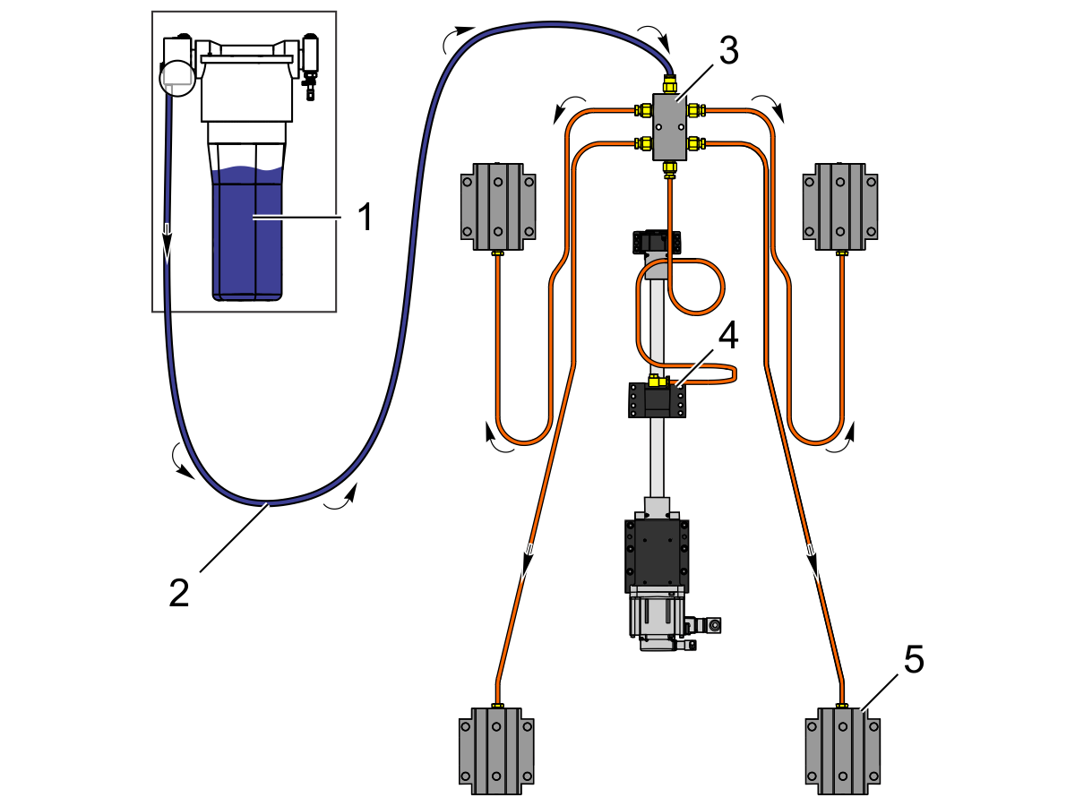
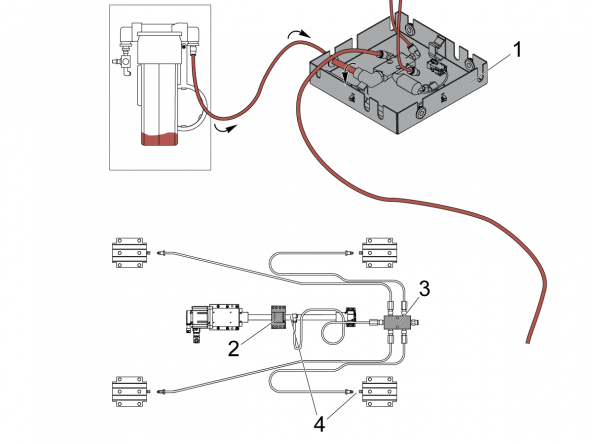
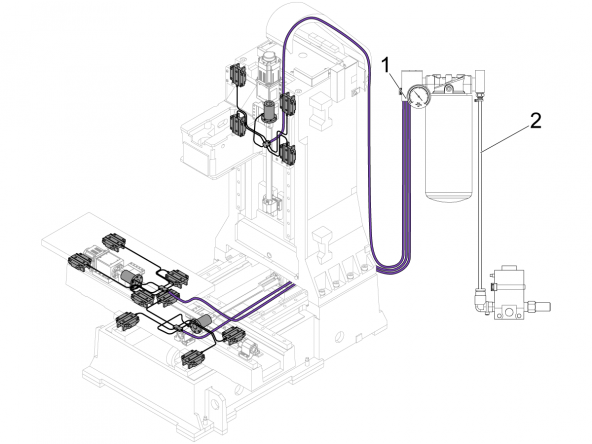
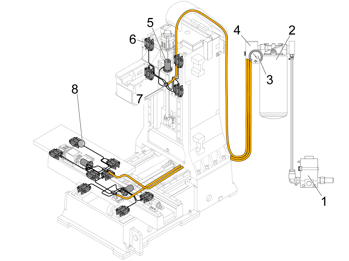
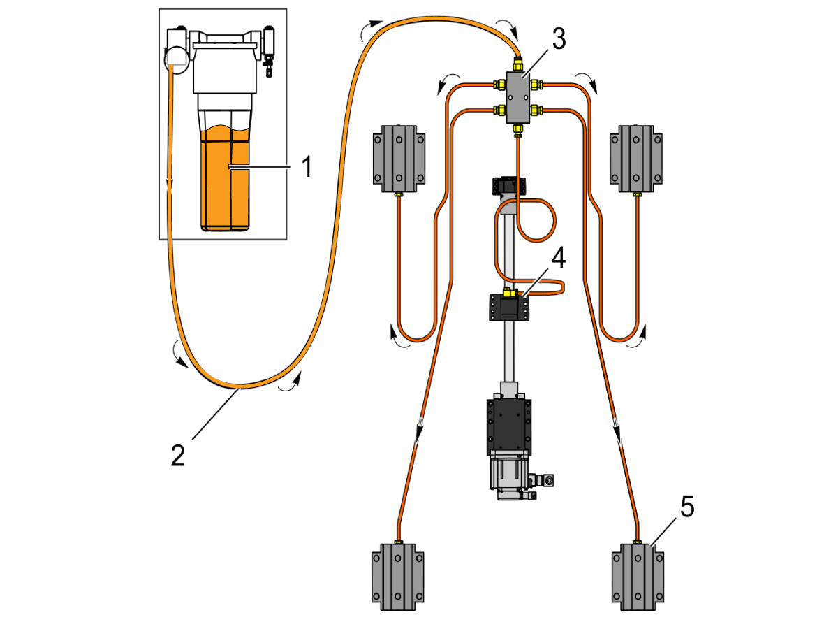
The oil reservoir [1] lubricates the axes at a rate of (1) oil cycle for every 3 hours of axis travel.

Oil moves from the oil reservoir [1] through flexible plastic tubing [2] to the axis manifolds [3].

Note: The number of axis manifolds may be different on some machines.

Note: Each axis has (1) ballnut [4] and (4-6 ) linear guide trucks [5].


Oil moves from the axis manifolds [3] through copper tubes. The copper tubes lubricate the ballnuts [4] and the linear guide trucks [5].

Note: There is (1) copper tube that goes to the ballnut and (1) copper tube that goes to each linear guide truck.


Note: The Haas Axis Lubrication Oil canister lasts approximately 10 months to a year under normal machine operation, 8 hours a day and 5 days per week.


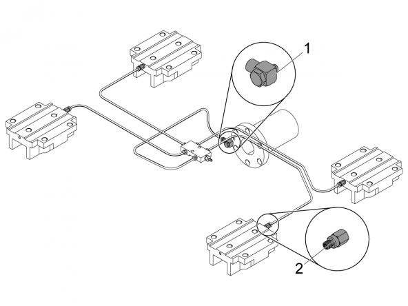
Axis Manifold Fitting Information

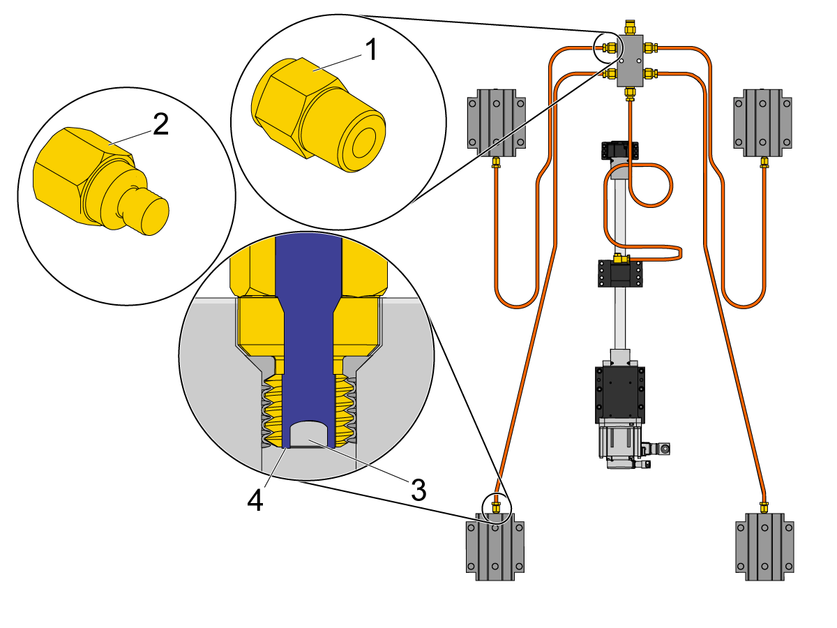
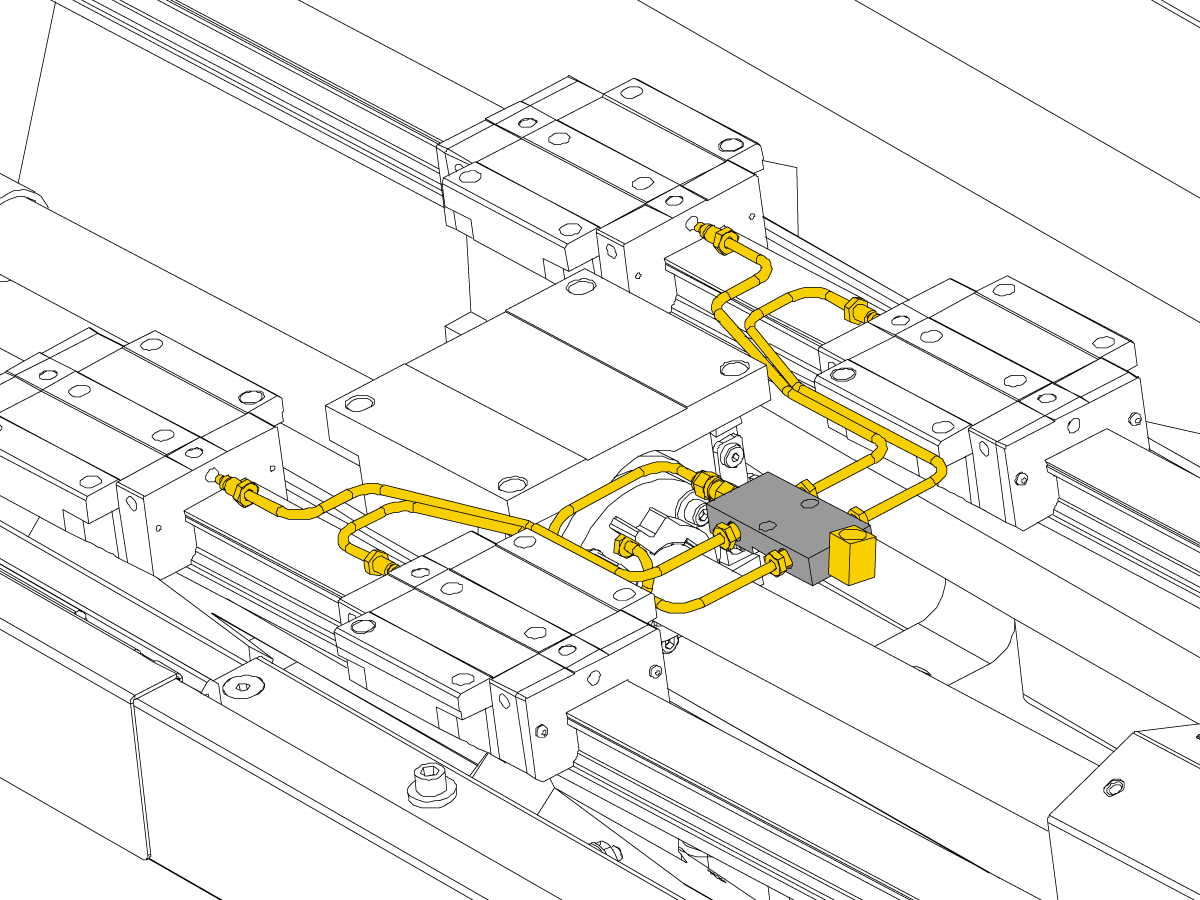
The Haas Axis Lubrication Oil system uses adapter fittings [1] in the axis manifolds. The linear guide trucks and ballnuts use restrictor fittings [2]. The restrictor fitting has a gap [4] between the threads and the set screw [3]. This forces the manifold-fed oil to pass through the gap [4] to lubricate the axes.

Note: The copper tubes on this system may or may not be equal length.

Caution: Do not change the length of the copper tubes or flexible plastic tubing. This changes the flow of oil.


Recently Updated

Haas Axis Lubrication Oil - Reservoir Refill


AD0630

Introduction

This procedure outlines how to refill the Haas Axis Lubrication Oil reservoir.

Axis Lubrication Has Changed From Grease to Oil - Service Update

This procedure applies to the following service kits:

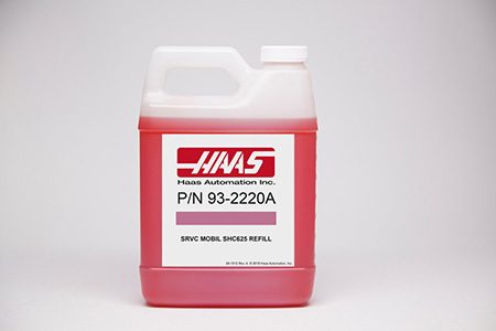
  • 93-3584: AXIS LUBE OIL REFILL 1 GALLON

Haas Axis Lubrication Oil - Refill

1

Power off the machine. Close the primary air valve. This stops the air supply to the machine.

Pull the ring on the pressure relief valve on the air and lubrication manifold. This releases the air pressure from the system.

Place shop towels under the reservoir to catch any grease that may fall.

Remove the empty reservoir. Use an automotive oil filter wrench to loosen it if the reservoir is too tight to loosen by hand.

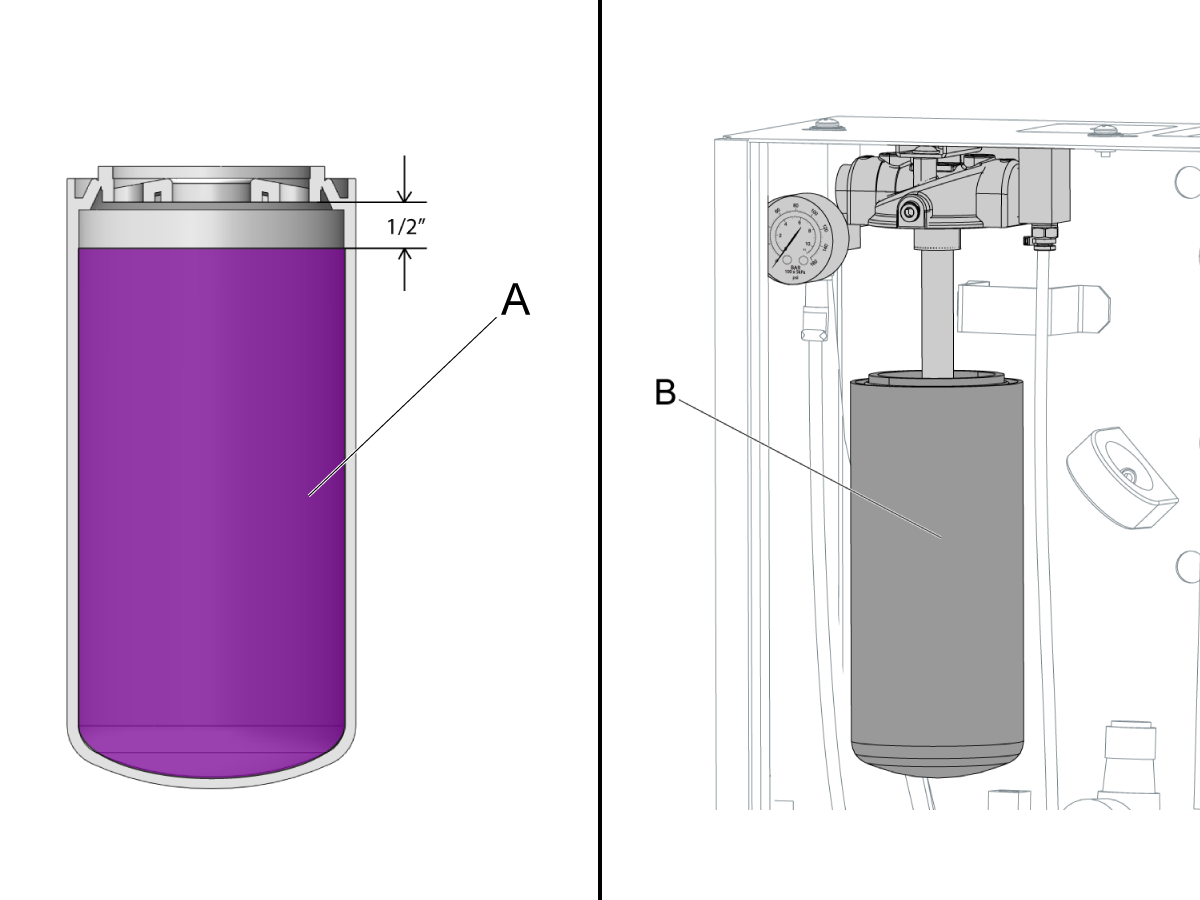
Pour the Haas Axis Lubrication Oil [A] into the reservoir to 1/2" (13 mm) below the threads on the reservoir.

Install the reservoir [B]. Use your hand to tighten it until the gasket makes contact with the reservoir head. Tighten another 3/4 turn.

Axis Lubrication System - Prime and Test

1

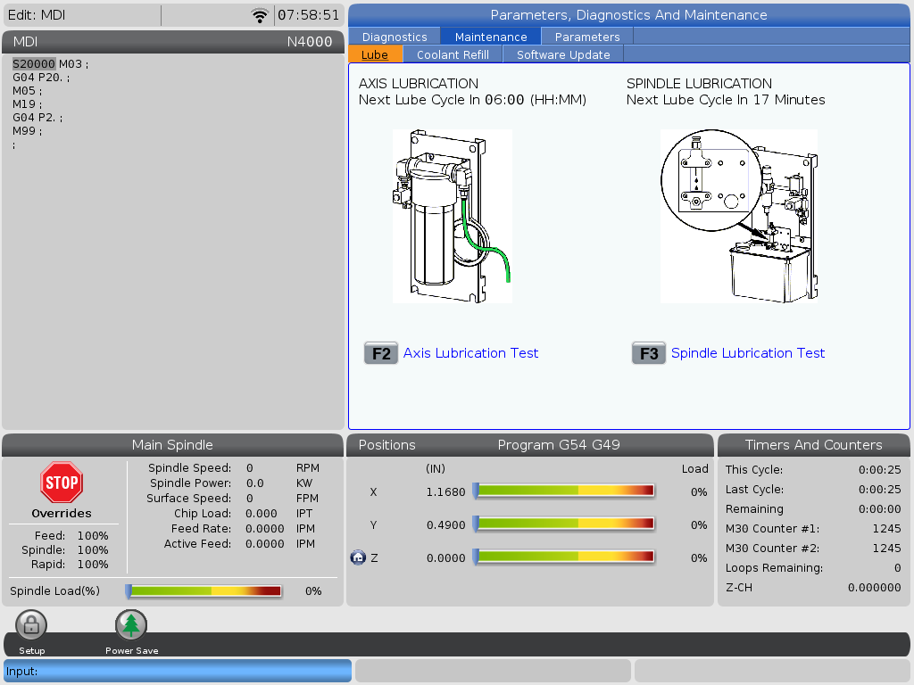
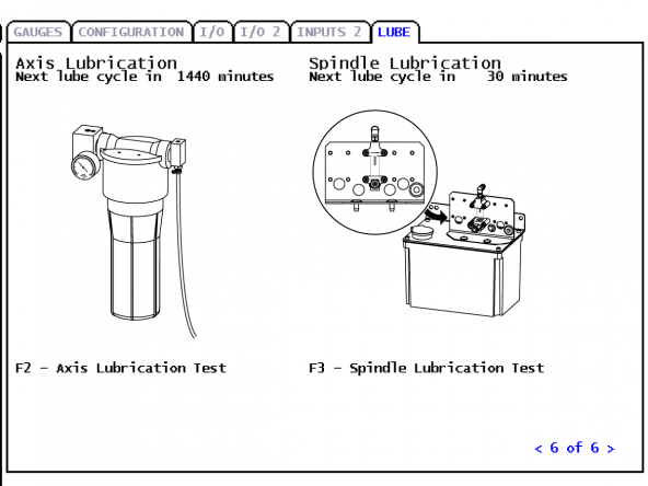
Press [DIAGNOSTICS].

Go to the Maintenance tab and navigate to the Lube tab.

Press [F2] to start the Axis Lubrication Test.

2

Perform the Axis Lubrication Test again until you no longer get axis lubrication alarms. Wait a minimum of (1) minute between Axis Lubrication Test cycles.

Check the level of the oil in the reservoir.

If the oil lines were nearly empty, it may be necessary to refill the axis lubrication reservoir after you purge the lines of air. Pour the oil into the reservoir to about 1/2" (13 mm) below the threads on the reservoir. 
 NOTE: If the machine has a C-axis, the C-axis gear lube hose must be disconnected from the lube panel manifold during the lubrication air purge process.

Recently Updated

Haas Axis Lubrication Oil - Conversion


AD0629

Applies to machines built from April, 2014 to August 2022

Introduction


Important: CHC Mills will need software M18.28 or higher and CHC Lathes will need software L11.24 or higher.
Service Techs performing the software update on CHC Mills should view this service news on the HSG site.

 Note: If your machine needs to upgrade to a metal reservoir from plastic, order kit 93-2601B and refer to the HLG Plastic to Metal Haas Axis Lube Oil (HALO) Reservoir - Conversion procedure.

This procedure will explain how to convert the axis lubrication system to Haas Axis Lubrication Oil on machines with Haas Liquid Grease.

Axis Lubrication Has Changed From Grease to Oil - Service Update

This procedure applies to the following service kits:

  • 93-3585: AXIS LUBE CONVERSION KIT HLG TO OIL
  • 93-3610: HALO SVC KIT CHECK VALVE

Note: Every Lathe will need at least one (1) of kit 93-3610. Lathes that also have a Y-Axis will need to order two (2) of kit 93-3610.

Note: UMC's will now need three (3) of kit 93-3610 to add check valves to all of the lubrication lines.

Important: Before ordering any check valves kits (93-3610) please verify the machines configuration in the images in the Install New Reservoir section below.

Before performing this procedure, verify the axis lubrication system is clear. This can be verified by running an Axis Lubrication Test in the Maintenance Tab. If Alarm 2082 is generated OR if the pressure has not gone back down in 1 hour, this is an indication that the axis lube lines are clogged.

If you need to purge axis lube lines refer to the following procedure: Haas Liquid Grease - Purge Clogged Lines. 
NOTE: If the machine has a C-axis, the C-axis gear lube hose must be disconnected from the lube panel manifold during the lubrication air purge process.

Once the lines have been purged and the pump manifold cleaned, continue on to the rest of this procedure.

Install New Reservoir

1

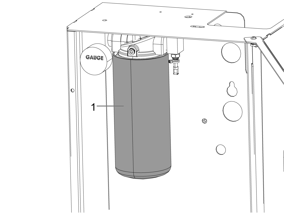
Fill the new reservoir [1] with the Haas Axis Lubrication Oil to about 1/2" (13 mm) below the threads on the reservoir.


2

Follow this step for Mills

Note: UMC's will now need three (3) of kit 93-3610 to add check valves to all of the lubrication lines, the check valves are grey in image [2] to show where they need to be added.

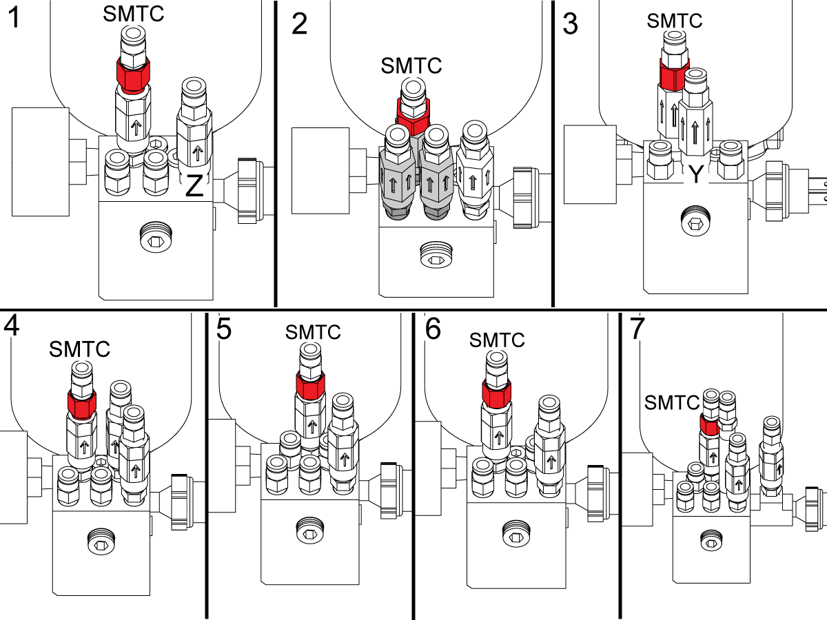
Mills with a SMTC will need to add a .02" orifice (shown as the red component in the images) to their lube lines on the oil reservoir. Use the numbered images and the following list to see where the orifice needs to be added on the following machines:

  1. SMTC: VF - 1-9, DT, DM, VR-8, VM - 2/3/6, VC-400
  2. UMC 350-1600
  3. EC-400/500/500-50T/630/630-50T
  4. GM-2, GM-2-5AX
  5. VF - 10/11/12/13/14, VR - 9/10/11/12/13/14
  6. VMT-750
  7. VS-1/3

Note: A small amount of SMTC's do not have a servo carousel and therefore will not need the additional orifice. This means that any mills that only have 3 grease lines on the lubrication reservoir do not need the additional orifice.

Note: Not all lubrication configurations are shown, only configurations that are adding new fittings in the conversion process are shown for reference on where the new fitting goes.

3

Follow this step for Lathes

Note: Every Lathe will need at least one (1) of kit 93-3610. Lathes that also have a Y-Axis will need to order two (2) of kit 93-3610.

 Note: Tail stock fittings are shown as the blue component in the images. 

Lathes with a C-Axis will need to add a .02" orifice (shown as the red component in the images) to their lube lines on the oil reservoir. Lathes will also need to add an extra check valve and nipple fitting to the X-Axis and the Y-Axis if it has one (the X and Y axes are labeled in the image to the right). Use the numbered images and the following list to see where the orifice and fittings need to be added on the following machines:

8. Longbed & Non-longbed: CL, ST-10/15/20/25/28/30/35

9. Y-Axis Longbed & Non-longbed: ST-10Y/ 15Y/20Y/25Y/28Y/30Y/35Y, ST-10LY/15LY/20LY/25LY/28LY/30LY/35LY

10. C-Axis Longbed & Non-longbed: ST-10/ 15/20/25/28/30/35

11. C-Axis & Y-Axis Longbed & Non-longbed: ST-10Y/ 15Y/20Y/25Y/30Y/35Y

12. Longbed & C-Axis & Y-Axis & Sub-Spindle: DS-30Y, ST-10LY/ 15LY/20LY/25LY/28LY/30LY/35LY

13. Longbed & Tail Stock: ST-40/40L/45/45L/50/55

14. Longbed & C-Axis & Tail Stock: ST-40/45/50/55

15. Longbed/Non-Longbed & Tail Stock: ST-30/35

16. Longbed/Non-Longbed & Tail Stock & Y-Axis: ST-30Y/35Y

Note: Not all lubrication configurations are shown, only configurations that are adding new fittings in the conversion process are shown for reference on where the new fitting goes.

Axis Lubrication System - Verification

1

For NGC machines:

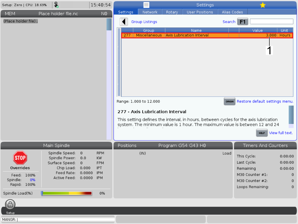
Change Setting 277 to 3 hours [1].


Note: Contact your HFO to download and apply the latest patch from the HBC site on their next visit.


For CHC machines:

Set Parameter 1401 to 12 hours and Setting 252 to 3 hours.

2

For NGC machines:

Press [DIAGNOSTICS].

Go to the Maintenance tab and navigate to the Lube tab.

Press [F2] to start the Axis Lubrication Test.


For CHC machines:

Press [PARAMETER DIAGNOSTIC] (2) times to show the diagnostics page.

Press [CANCEL].

Go to the LUBE tab.

Press [WRITE/ENTER].

Press [F2] to start the Axis-Lubrication Test.

3

Perform the Axis Lubrication Test again until you no longer get axis lubrication alarms. Wait a minimum of (1) minute between Axis Lubrication Test cycles.

Check the level of the oil in the reservoir.

If the oil lines were nearly empty, it may be necessary to refill the axis lubrication reservoir after you purge the lines of air. Pour the oil into the reservoir to about 1/2" (13 mm) below the threads on the reservoir.

Recently Updated

Red Grease to Haas Axis Lubrication Oil - Conversion


AD0659

Introduction


Important: CHC Mills will need software M18.28 or higher and CHC Lathes will need software L11.24 or higher.
Service Techs performing the software update on CHC Mills should view this service news on the HSG site.

This procedures tells you how to convert a machine with red SHC 007 axis lubrication grease to Haas Axis Lubrication Oil. The Haas Axis Lubrication Oil system uses a different reservoir assembly and different fittings at the linear guide trucks and ballscrew.

This procedure applies to the following service kits:

  • 93-2755A: HAAS AXIS LUBE OIL RETROFIT KIT
  • 93-3610: HALO SVC KIT CHECK VALVE

Note: Every Lathe will need at least one (1) of kit 93-3610. Lathes that also have a Y-Axis will need to order two (2) of kit 93-3610.

Note: UMC's will now need three (3) of kit 93-3610 to add check valves to all of the lubrication lines.

Important: Before ordering any check valves kits (93-3610) please verify the machines configuration in the images in the Install New Reservoir section below.

 IMPORTANT: If the machine has SKF branded linear guides contact Haas Service.

Required Cable:

A low grease sensor cable (CBL500 LOW GREASE SENSOR) must be ordered with 93-2755 from the table below.

Note : The cable required is the A version of the cable that is currently installed on the machine (Applicable to machines built before 3/17/15).

Part Number Machine Compatibility Length (ft)
33-10044A VF-1
OL-1
ST-50/55
11.7
33-0240A ST-10/20/20Y/30/30Y
DS-30/30Y
OM-1
EC-400/400P/500
16
33-0289A ST-40/40L 24
33-0389A GR510/712 40

Prerequisites:

The machine must have software version M18.28 or higher or L11.24 or higher. Change Setting 252 to a value of 3. Make sure to change the parameter values in the table below.

Parameter Name Value
810 AXIS LUBE TYPE 5
811 AX INTRVL METERS Use the Parameter Checker to find the value for your machine.
815 AX LUBE INPUT 25
816 AX LUBE OUTPUT 52
861 AX LUBE TIME INTRVL 480
1374 AX LUBE TYPE 5 MAXIMUM PRESSURE RISE TIME (ms) 3000
1375 AX LUBE TYPE 5 MINIMUM PRESSURE DURATION (ms) 15000
1401 Power-On Axis Lubrication Time Interval 12

Conversion

1

Remove the existing lubrication system.

Remove the waycovers necessary to get access to the axis manifold [3] and ballscrew [2] for each axis.

Get access to the lubrication housing box [1] between the column and base casting.

Disconnect the copper tubes from the ballnut and linear guide trucks [4]. Use shop air to blow the remaining red grease out of the copper tubes.

Remove and discard the grease tubes to each axis and everything inside the lubrication housing box [1].

 IMPORTANT: If the machine has SKF branded linear guides contact Haas Service.

2

Install fittings and new reservoir.

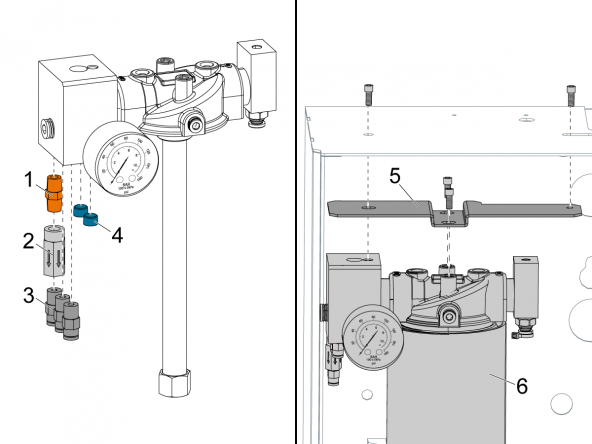
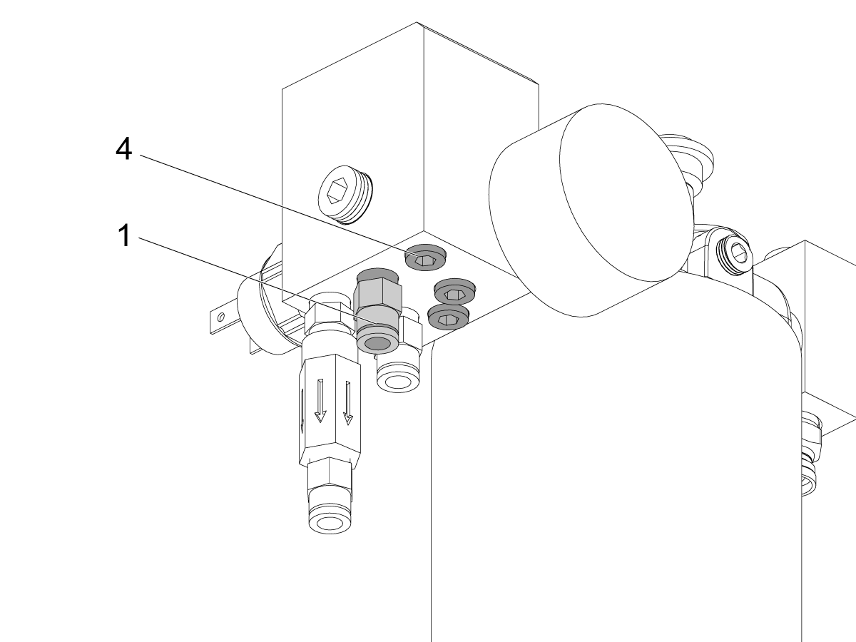
Install the brass nipple fitting [1], check valve [2], and hose fitting [3] to one of the ports on the grease manifold.

Install the other two hose fittings [3] to open ports on the oil manifold.

Install the two plugs [4] in the remaining two open ports.

Remove the red grease reservoir assembly.

Install the Haas Axis Lube Oil reservoir assembly and air tube. Use the bracket [5] to install the assembly to the lubrication cabinet. Install the metal reservoir with Haas Axis Lube Oil [6].

Connect the pressure switch cable to the pressure switch behind the oil manifold.

3

Install new clear lubrication tubes.

Install new tubes from the ports [1] on the oil manifold to each axis.

Note: The tube that supplies the vertical axis must be plugged into the port with the check valve. This is the z-axis in a VF or MM, the y-axis in an EC, or the x-axis in an ST.

Connect the air hose [2] from the solenoid on the air manifold to the Haas Axis Lube Oil reservoir assembly.

4

Install the banjo and restrictor fittings.

Remove the fittings at the ballscrew and at each linear guide truck.

Install the banjo fitting [1] at the ballscrew port. Torque the banjo fitting to 10 in-lbs. Be very careful here; if you exceed 10 in-lbs you will break the banjo bolt.

Install the restrictor fittings [2] at each linear guide truck port.

Torque the restrictor fittings as follows:

  • For linear guide brand Rexroth: 15 in-lbs
  • For linear guide brands INA, NSK, and THK: 12 in-lbs

Install New Reservoir

1

Fill the new reservoir [1] with the Haas Axis Lubrication Oil to about 1/2" (13 mm) below the threads on the reservoir.


2

Follow this step for Mills

Note: UMC's will now need three (3) of kit 93-3610 to add check valves to all of the lubrication lines, the check valves are grey in image [2] to show where they need to be added.

Mills with a SMTC will need to add a .02" orifice (shown as the red component in the images) to their lube lines on the oil reservoir. Use the numbered images and the following list to see where the orifice needs to be added on the following machines:

  1. SMTC: VF - 1-9, DT, DM, VR-8, VM - 2/3/6, VC-400
  2. UMC 350-1600
  3. EC-400/500/500-50T/630/630-50T
  4. GM-2, GM-2-5AX
  5. VF - 10/11/12/13/14, VR - 9/10/11/12/13/14
  6. VMT-750
  7. VS-1/3

Note: A small amount of SMTC's do not have a servo carousel and therefore will not need the additional orifice. This means that any mills that only have 3 grease lines on the lubrication reservoir do not need the additional orifice.

Note: Not all lubrication configurations are shown, only configurations that are adding new fittings in the conversion process are shown for reference on where the new fitting goes.

3

Follow this step for Lathes

Note: Every Lathe will need at least one (1) of kit 93-3610. Lathes that also have a Y-Axis will need to order two (2) of kit 93-3610.

 Note: Tail stock fittings are shown as the blue component in the images. 
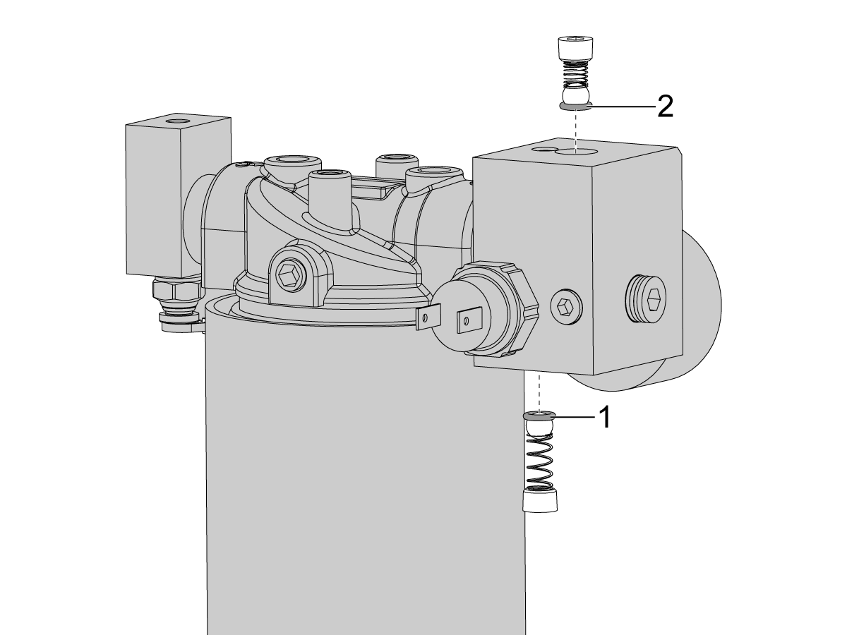
Lathes with a C-Axis will need to add a .02" orifice (shown as the red component in the images) to their lube lines on the oil reservoir. Lathes will also need to add an extra check valve and nipple fitting to the X-Axis and the Y-Axis if it has one (the X and Y axes are labeled in the image to the right). Use the numbered images and the following list to see where the orifice and fittings need to be added on the following machines:
8. Longbed & Non-longbed: CL, ST-10/15/20/25/28/30/35

9. Y-Axis Longbed & Non-longbed: ST-10Y/ 15Y/20Y/25Y/28Y/30Y/35Y, ST-10LY/15LY/20LY/25LY/28LY/30LY/35LY

10. C-Axis Longbed & Non-longbed: ST-10/ 15/20/25/28/30/35

11. C-Axis & Y-Axis Longbed & Non-longbed: ST-10Y/ 15Y/20Y/25Y/30Y/35Y

12. Longbed & C-Axis & Y-Axis & Sub-Spindle: DS-30Y, ST-10LY/ 15LY/20LY/25LY/28LY/30LY/35LY

13. Longbed & Tail Stock: ST-40/40L/45/45L/50/55

14. Longbed & C-Axis & Tail Stock: ST-40/45/50/55

15. Longbed/Non-Longbed & Tail Stock: ST-30/35

16. Longbed/Non-Longbed & Tail Stock & Y-Axis: ST-30Y/35Y
Note: Not all lubrication configurations are shown, only configurations that are adding new fittings in the conversion process are shown for reference on where the new fitting goes.

Oil Reservoir - Prime and Test

1

Press [PARAMETER DIAGNOSTIC] (2) times to show the diagnostics page.

Press [CANCEL].

Go to the [LUBE] tab.

Press [WRITE/ENTER] .

Press [F2] to start the Axis-Lubrication Test.

2

Perform the Axis-Lubrication Test again until you no longer get axis lubrication alarms. Wait a minimum of (1) minute between Axis-Lubrication Test cycles.

Check the level of the oil in the reservoir.

If the oil lines were nearly empty, it may be necessary to refill the axis-lubrication reservoir after you purge the lines of air. Pour the oil into the reservoir: to about 1/2" (13mm) below the threads on the reservoir.

Recently Updated

HLG Plastic to Metal Haas Axis Lube Oil (HALO) Reservoir - Conversion


AD0660

Introduction


Important: CHC Mills will need software M18.28 or higher and CHC Lathes will need software L11.24 or higher.
Service Techs performing the software update on CHC Mills should view this service news on the HSG site.

This procedure will explain how to convert the HLG Plastic reservoir axis lubrication system to Haas Axis Lubrication Oil with the metal reservoir.

This procedure applies to the following service kits:

  • 93-2601B: AXIS LUBE RSRV METAL HAAS AXIS LUBE OIL
  • 93-3610: HALO SVC KIT CHECK VALVE

Note: Every Lathe will need at least one (1) of kit 93-3610. Lathes that also have a Y-Axis will need to order two (2) of kit 93-3610.

Note: UMC's will now need three (3) of kit 93-3610 to add check valves to all of the lubrication lines.

Important: Before ordering any check valves kits (93-3610) please verify the machines configuration in the images in the Install New Reservoir section below.

Before performing this procedure, verify the axis lubrication system is clear. This can be verified by running an Axis Lubrication Test in the Maintenance Tab. If Alarm 2082 is generated OR if the pressure has not gone back down in 1 hour, this is an indication that the axis lube lines are clogged.

If you need to purge axis lube lines refer to the following procedure: Haas Liquid Grease - Purge Clogged Lines. 

Once the lines have been purged and the pump manifold cleaned, continue on to the rest of this procedure.

Axis-Lubrication Reservoir Assembly- Replacement

1

Label the output grease hoses from the used axis-lubrication reservoir assembly so they can be put back in the same location when you are finished replacing the assembly.

Disconnect the input air hose and output grease hoses from the used axis-lubrication reservoir.

Remove the used axis-lubrication reservoir assembly from the cabinet.

Disconnect the pressure switch cable from the assembly.

Remove the air input fitting and the grease manifold fro the used axis-lubrication reservoir assembly.

2

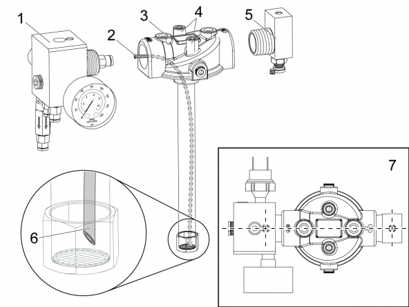
Remove and discard the used 1/4" OD tube (same location as a new hose [2] shown in image) from the oil manifold [1].

Install the air input fitting [5] into the new axis-lubrication reservoir assembly [3]. Orient the top of the air input fitting parallel to the two screw bosses [4] on the new axis-lubrication reservoir [3]. 

Look at the bottom tip of the hose [5]. Verify:

  • The tip must be cut at 45 degrees.
  • It must clear the filter screen by approximately 1/16" (2mm).
  • If it is necessary to shorten the hose, cut it at the top.
    • Leave enough hose to make a good connection with the oil manifold [1].
    • Do not kink the hose.

Do not pull the new tube completely out of the port on the head. only pull the new 1/4" OD tube [2] one or two inches from the port on the head of the new axis-lubrication reservoir assembly that has the "OUT" label. Insert the tube until it is firmly seated in the fitting in the oil manifold [1].

Install the oil manifold [1] into the new axis-lubrication reservoir assembly [3]. The holes on top of the air input fitting [4] and oil manifold [1] must be aligned as shown [6].

3

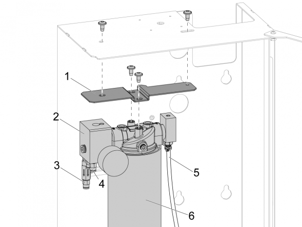
Install the metal reservoir with oil [6]. Install the completed new axis-lubrication reservoir assembly into the cabinet.

Use the adapter bracket [1] if the holes in the cabinet do not match the holes in the head assembly. Make sure the bracket is oriented as shown. 

Note: Damage can occur over time if the vertical axis hose is not connected to an output with a check valve. Air can get into the hose and the vertical axis won't get adequate lubrication.

Connect the input air hose [5] and output grease hoses. Make sure to install the vertical axis to the output port with the check valve [3]. The other axes are installed on the hose fittings [4].

Connect the pressure switch cable to the pressure switch behind the oil manifold [2].

Install New Reservoir

1

Fill the new reservoir [1] with the Haas Axis Lubrication Oil to about 1/2" (13 mm) below the threads on the reservoir.


2

Follow this step for Mills

Note: UMC's will now need three (3) of kit 93-3610 to add check valves to all of the lubrication lines, the check valves are grey in image [2] to show where they need to be added.

Mills with a SMTC will need to add a .02" orifice (shown as the red component in the images) to their lube lines on the oil reservoir. Use the numbered images and the following list to see where the orifice needs to be added on the following machines:

  1. SMTC: VF - 1-9, DT, DM, VR-8, VM - 2/3/6, VC-400
  2. UMC 350-1600
  3. EC-400/500/500-50T/630/630-50T
  4. GM-2, GM-2-5AX
  5. VF - 10/11/12/13/14, VR - 9/10/11/12/13/14
  6. VMT-750
  7. VS-1/3

Note: A small amount of SMTC's do not have a servo carousel and therefore will not need the additional orifice. This means that any mills that only have 3 grease lines on the lubrication reservoir do not need the additional orifice.

Note: Not all lubrication configurations are shown, only configurations that are adding new fittings in the conversion process are shown for reference on where the new fitting goes.

3

Follow this step for Lathes

Note: Every Lathe will need at least one (1) of kit 93-3610. Lathes that also have a Y-Axis will need to order two (2) of kit 93-3610.

 Note: Tail stock fittings are shown as the blue component in the images. 

Lathes with a C-Axis will need to add a .02" orifice (shown as the red component in the images) to their lube lines on the oil reservoir. Lathes will also need to add an extra check valve and nipple fitting to the X-Axis and the Y-Axis if it has one (the X and Y axes are labeled in the image to the right). Use the numbered images and the following list to see where the orifice and fittings need to be added on the following machines:

8. Longbed & Non-longbed: CL, ST-10/15/20/25/28/30/35

9. Y-Axis Longbed & Non-longbed: ST-10Y/ 15Y/20Y/25Y/28Y/30Y/35Y, ST-10LY/15LY/20LY/25LY/28LY/30LY/35LY

10. C-Axis Longbed & Non-longbed: ST-10/ 15/20/25/28/30/35

11. C-Axis & Y-Axis Longbed & Non-longbed: ST-10Y/ 15Y/20Y/25Y/30Y/35Y

12. Longbed & C-Axis & Y-Axis & Sub-Spindle: DS-30Y, ST-10LY/ 15LY/20LY/25LY/28LY/30LY/35LY

13. Longbed & Tail Stock: ST-40/40L/45/45L/50/55

14. Longbed & C-Axis & Tail Stock: ST-40/45/50/55

15. Longbed/Non-Longbed & Tail Stock: ST-30/35

16. Longbed/Non-Longbed & Tail Stock & Y-Axis: ST-30Y/35Y

Note: Not all lubrication configurations are shown, only configurations that are adding new fittings in the conversion process are shown for reference on where the new fitting goes.

Axis Lubrication System - Verification

1

For NGC machines:

Change Setting 277 to 3 hours [1].


Note: Contact your HFO to download and apply the latest patch from the HBC site on their next visit.


For CHC machines:

Set Parameter 1401 to 12 hours and Setting 252 to 3 hours.

2

For NGC machines:

Press [DIAGNOSTICS].

Go to the Maintenance tab and navigate to the Lube tab.

Press [F2] to start the Axis Lubrication Test.


For CHC machines:

Press [PARAMETER DIAGNOSTIC] (2) times to show the diagnostics page.

Press [CANCEL].

Go to the LUBE tab.

Press [WRITE/ENTER].

Press [F2] to start the Axis-Lubrication Test.

3

Perform the Axis Lubrication Test again until you no longer get axis lubrication alarms. Wait a minimum of (1) minute between Axis Lubrication Test cycles.

Check the level of the oil in the reservoir.

If the oil lines were nearly empty, it may be necessary to refill the axis lubrication reservoir after you purge the lines of air. Pour the oil into the reservoir to about 1/2" (13 mm) below the threads on the reservoir.

Introduction

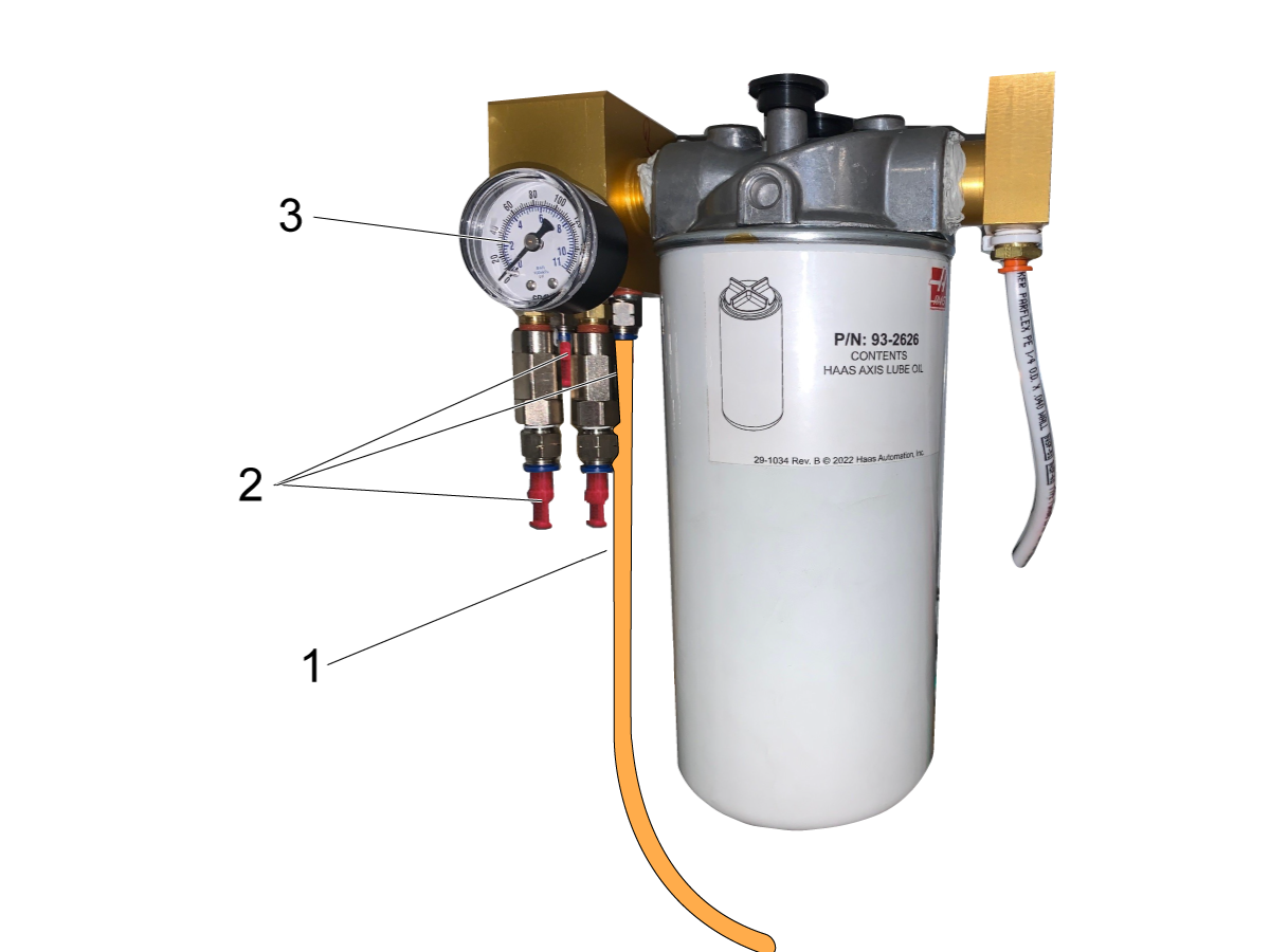
  1. Axis-Lube Air Solenoid
  2. Metal Canister Oil Reservoir
  3. Air Pressure Gauge
  4. HALO Manifold
  5. Ballnut
  6. Linear Guide Truck
  7. Axis Oil Manifold
  8. Orifice Fitting - Oil flows in a helical shape around a set screw and oversize drilled thread. Do not remove the set screw from the orifice fitting.
  9. Pressure Sensor: 4 PSI switch, normally open (not shown, located behind [4])
Alarm 2075 Checklist

System Operation Overview

The Haas Axis lubrication Oil system utilizes shop air pressure to pressurize the HALO reservoir via a 120VAC solenoid. Both components are located inside the air/lube cabinet

The lubrication cycle will be initiated when:

  1. The axes have been in motion for the time specified in Setting 277 (3 hours by default).
  2. The machine has been idle for 12 hours (specified in Parameter 1401).
  3. If the user presses [F2] while in the LUBE MAINTENANCE section of the DIAGNOSTIC display.

The HALO manifold has two internal check valves [1] and [2]; internal snubber before the check valve [2]; the pressure gauge and the 4 PSI normally open pressure switch [3]. There are multiple lubrication lines coming out of the HALO manifold depending on the machine type and configuration. The lubrication lines that are routed above the air/oil pump will have a check valve [4] at the HALO manifold to prevent the oil from draining from the lines back to the reservoir between the lubrication cycles.

When a lubrication cycle is commanded, the solenoid applies air pressure to the HALO reservoir for 3 seconds (specified in Parameter 2027), which forces the oil to move up the pick-up tube [5] and into the HALO manifold. The oil flows through the lubrication lines to the lubrication points where it gets pushed through the restrictors into the components that require the lubrication (ballscrew, linear guides pads, etc). Once the cycle ends, the pressure from the HALO reservoir is vented to the atmosphere, the check valve [1] traps the pressurized oil in the manifold and it will start to flow through the snubber and the check valve [2] back to the HALO canister until the pressure in the manifold drops to 0 PSI.

During the lubrication cycle the control monitors the pressure in the lubrication manifold in order to detect a failure of the lubrication system.

When the solenoid is commanded to turn on, the control begins to monitor the status of the pressure switch [3]. The switch is expected to close within 3 seconds (specified in Parameter 1374) from the moment that the solenoid was commanded ON. Once the pressure is detected it is expected to stay for at least 15 seconds (specified in Parameter 1375). If all of the above statements were satisfied during the cycle then the lubrication cycle is considered successful.

If pressure in the system was not detected within 3 seconds (specified in the Parameter 1374) the control will stop monitoring the pressure and display the “Low Lube” warning icon until the next lube cycle. If such a condition was detected for 5 consecutive lube cycles, then the control will generate the Alarm 2073 AXIS LUBRICATION PRESSURE NOT DETECTED. The alarm will not be generated during a program execution, it will only be generated after the program execution ends or after pressing a [RESET] button.

If the pressure in the system drops below 4 PSI before 15 seconds (specified in Parameter 1375), the control will display “Low Lube” warning icon until the next lube cycle. If such a condition is detected for the next 4 consecutive lube cycles (5 total cycles) the control will generate the Alarm 2075 AXIS LUBRICATION RESERVOIR IS EMPTY. The alarm will not be generated during a program execution. It will be generated after the program execution ends or after pressing a [RESET] button.

Symptom Table

Symptom Possible Cause Corrective Action

Low Lube Icon

When the axis lube solenoid was commanded the system never detected pressure or the pressure duration was too short. Inspect the reservoir assembly and make sure the check valves are not stuck or sticking. Also refer to the Check Valve O-rings section below to verify the o-rings are seated properly.
Alarm 2075 AXIS LUBRICATION RESERVOIR EMPTY Air in axis lubrication line. The reason for the air in the lines needs to be identified and corrected. See the ALARM 2075: AXIS LUBRICATION RESERVIOR EMPTY section.
The check valves may be sticking and causing excessive oil usage. Inspect the reservoir assembly and make sure the check valves are not stuck or sticking. Also refer to the Check Valve O-rings section below to verify the o-rings are seated properly.
There may be debris in the HALO manifold and/or in front of the pressure sensor. Clean out the HALO manifold and clean around the pressure switch.
There may be air in the lube lines. Prime the lube lines and make sure no air is leaking from the HALO manifold when the system is pressurized.
Lathes do not have an added check valve on their x-axis and y-axis (if applicable) lubrication lines. Verify the lathe has the correct amount of check valves on its lubrication lines, the configurations can be seen below in the HALO Lubrication Lines Configurations section.
UMC's do not have the added check valves to their lubrication lines. Verify the UMC has the correct amount of check valves on its lubrication lines, the configurations can be seen below in the HALO Lubrication Lines Configurations section.
The correct configuration of check valves needed may not be installed in the HALO manifold. Verify the correct amount of check valves are on the lubrication lines, the configurations can be seen below in the HALO Lubrication Lines Configurations section.
Alarm 2073 AXIS LUBRICATIONPRESSURE NOT DETECTED Solenoid not supplying air to HALO system. See solemoid troubleshooting section in the Alarm 2075 section below.
Pressure switch not changing states. See section 4-5 of the Alarm 2075 troubleshooting guide
When refilling the oil reservoir, the filter is found to be crushed at the bottom. The pressure in the oil reservoir can cause the bottom of the filter to crush. A new filter that is reinforced has been created and can replace the old crushed filter. Order part number 58-2072A to replace a crushed filter.

HALO Lubrication Lines Configurations


Mill Lubrication Lines

Note: UMC's will now need three (3) of kit 93-3610 to add check valves to all of the lubrication lines, the check valves are grey in image [2] to show where they need to be added.

Mills with a SMTC will need to add a .02" orifice (shown as the red component in the images) to their lube lines on the oil reservoir. Use the numbered images and the following list to see where the orifice needs to be added on the following machines:

  1. SMTC: VF - 1-9, DT, DM, VR-8, VM - 2/3/6, VC-400
  2. UMC 350-1600
  3. EC-400/500/500-50T/630/630-50T
  4. GM-2, GM-2-5AX
  5. VF - 10/11/12/13/14, VR - 9/10/11/12/13/14
  6. VMT-750
  7. VS-1/3

Note: A small amount of SMTC's do not have a servo carousel and therefore will not need the additional orifice. This means that any mills that only have 3 oil lines on the lubrication reservoir do not need the additional orifice.

Note: Not all lubrication configurations are shown, only configurations that are adding new fittings in the conversion process are shown for reference on where the new fitting goes.

Lathe Lubrication Lines

Note: Every Lathe will need at least one (1) of kit 93-3610. Lathes that also have a Y-Axis will need to order two (2) of kit 93-3610.

 Note: Tail stock fittings are shown as the blue component in the images. 

Lathes with a C-Axis will need to add a .02" orifice (shown as the red component in the images) to their lube lines on the oil reservoir. Lathes will also need to add an extra check valve and nipple fitting to the X-Axis and the Y-Axis if it has one (the X and Y axes are labeled in the image to the right). Use the numbered images and the following list to see where the orifice and fittings need to be added on the following machines:

8. Longbed & Non-longbed: CL, ST-10/15/20/25/28/30/35

9. Y-Axis Longbed & Non-longbed: ST-10Y/ 15Y/20Y/25Y/28Y/30Y/35Y, ST-10LY/15LY/20LY/25LY/28LY/30LY/35LY

10. C-Axis Longbed & Non-longbed: ST-10/ 15/20/25/28/30/35

11. C-Axis & Y-Axis Longbed & Non-longbed: ST-10Y/ 15Y/20Y/25Y/30Y/35Y

12. Longbed & C-Axis & Y-Axis & Sub-Spindle: DS-30Y, ST-10LY/ 15LY/20LY/25LY/28LY/30LY/35LY

13. Longbed & Tail Stock: ST-40/40L/45/45L/50/55

14. Longbed & C-Axis & Tail Stock: ST-40/45/50/55

15. Longbed/Non-Longbed & Tail Stock: ST-30/35

16. Longbed/Non-Longbed & Tail Stock & Y-Axis: ST-30Y/35Y

Note: Not all lubrication configurations are shown, only configurations that are adding new fittings in the conversion process are shown for reference on where the new fitting goes.

ALARM 2075: AXIS LUBRICATION RESERVIOR EMPTY

 Note: The specification for Haas Axis Lubrication Oil changed as of 2/2025. It is highly reccommended that HALO systems be converted to the current standard to prevent alarm 2075.

Lubricant, Grease, and Sealant Tables for Haas Machine Components

OIL REFILL, AXIS LUBE OIL - 1 GL / 3.78 L

1

Verify that the oil reservoir [A] is full.

Verify the machine is getting correct air pressure on the gauge [7], and on the gauges page on the Haas control.

Verify that air is being delivered to the HALO manifold [1 & 2] by manually triggering the solenoid. 

Verify that there are no leaks on the air line [5] between the solenoid and the HALO manifold.

Verify that the solenoid [6] works properly. Remove the air line [5] from the HALO manifold and run an axis lubrication cycle. 

   DIAGNOSTIC > MAINTENCANCE > LUBE    

 Note: If your machine has had an upgrade from the Haas liquid Grease (HLG) to the Haas Axis Lubrication Oil (HALO) then you must ensure you also apply the relating patch which modifies lubrication parameters.

Axis Lubrication Has Changed From Grease to Oil

 Note: Monthly maintenance procedures state that the axis lubrication oil should be checked once a month. Neglecting the alarm can cause air to be introduced into the lines affecting the function of the system. 

VMC Maintenance Schedule

Lathe - Maintenance - Haas Service Manual

SOLENOID TROUBLESHOOTING

2

Inspect the axis-lube air solenoid.

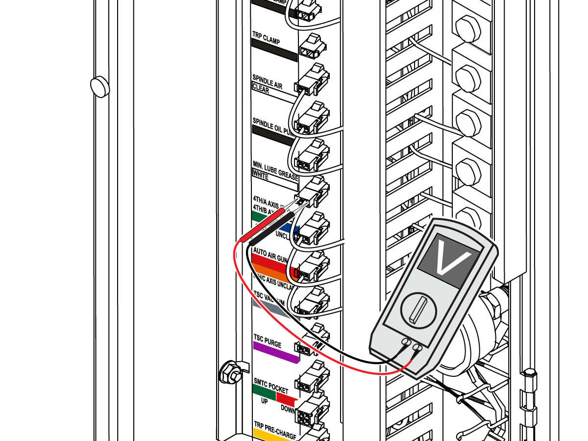
Do the Axis Lubrication Test and make sure the voltage to the HALO solenoid is 120 VAC.

 Note: Do not measure the voltage with the HALO solenoid disconnected from the connector.

Refer to the I/O PCB - Troubleshooting Guide (Classic Haas Control) to troubleshoot the I/O PCB.

Refer to the Solenoid Troubleshooting Guide to troubleshoot the solenoid.

If the solenoid is not activating when commanded, check for:

  • The connector being in the correct location.
  • Loose or broken wires.
  • Air coming out of the solenoid without the tube connected.
  • Firm solenoid cable connection at the I/O board.

3

Verify that the manifold is configured properly, reference the HALO LUBRICATION LINES CONFIGURATIONS section above.

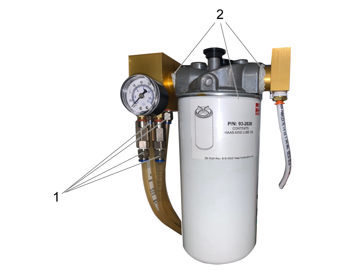
Verify that the HALO manifold and reservoir [2] are not leaking. 

Verify that all lines are properly secured into their push connect fittings [1] and that the threaded fittings are fastened tightly.

 Note: Vertical axes and SMTC lines will likely include check valves.

4

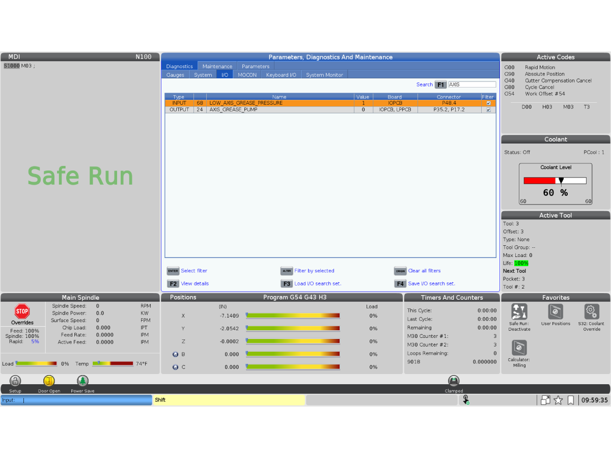
Check the states on the I/O tab for the solenoid output and the pressure gauge input. 

Run the axis lubrication cycle.

    DIAGNOSTIC > MAINTENCANCE > LUBE  

Observe the value changes in the I/O tab while the cycle takes place to verify the bits are changing.

  • The pressure gauge input should change from a 1 to 0 and back to 1 during the cycle.
  • The  solenoid output should change from a 0 to 1 and back to 0 during the cycle.
NAME P# TYPE SW# HW# CONNECTOR INITIAL VALUE
LOW_AXIS_GREASE_PRESSURE P48 INPUT 24 IO20 P48.47 1
AXIS_GREASE_PUMP P17, P15 OUTPUT 68 O003 P35.2, P17.2 0

PRESSURE SWITCH TROUBLESHOOTING

5

If the LOW_AXIS_GREASE_PRESSURE input does not change states.

 Note: For NGC check the software version on the machine. The machine must have software version 100.16.000.1020 or higher. Update the machine software if necessary.

Disconnect the cables from the pressure switch and use a jumper to connect them as shown. The pressure switch is behind the grease manifold

  • If the input changes from a 1 to a 0, the pressure switch is working properly.

Measure continuity from the IO board to the switch.

  • If there is no continuity then the cable may be bad.

Measure the resistance across the the pressure switch terminals while running the lube cycle.

  • If the resistance reads 'OL' then measures a value of resistance then reads 'OL' again the pressure switch is working properly. If it does not then the pressure switch may be faulty.

MANIFOLD TROUBLESHOOTING

6

Remove all oil lines and plug all ports [1] on the HALO manifold and activate the lube cycle.

    DIAGNOSTIC > MAINTENCANCE > LUBE  

If the pressure drop at the HALO manifold gauge [2] is less than 15 seconds it will generate the low lube icon, this indicates that there is a leak in manifold and requires further troubleshooting.

If the manifold holds pressure for longer than 15 seconds and no icon shows on the monitor, it is working as intended, and the rest of the system needs to be troubleshot.

7

If the HALO manifold pressure falls rapidly remove and check the condition of the manifold's check valves [1 & 2] located at the top and bottom.

Inspect the assembly and make sure the check valves are not stuck or sticking. Clean and replace where necessary.

Check for air and oil leaks around all connections and ports.

LUBRICATION LINE TROUBLESHOOTING

8

To test for a failed line that is leaking:

  • Choose one non-check valve port to test with [1]. For UMC machines a push connect fitting can be installed on one of the unused ports [4] at the bottom of the HALO manifold.
  • Remove and mark the position of the oil lines.
  • Plug all ports except the chosen non-check valve port [2] on the HALO manifold.
  • Pick a line to test and connect it into the chosen non-check valve port. Manually actuate the solenoid for 10 seconds and wait for the pressure guage to drop to zero psi. Repeat this step until the line holds for longer than 15 seconds.
  • Activate the axis lubrication cycle with the chosen line to determine if the system will generate low reservoir icon or the 2075 alarm.

  Run the axis lubrication cycle.

        DIAGNOSTIC > MAINTENCANCE > LUBE

  • If the machine generates the 2075 alarm or Low lube icon message, this can indicate that the system is not fully purged. Continue manual actuation of the solenoid. 
  • If the pressure is consistently dropping rapidly this indicates an issue down the line and it needs to be fully troubleshot.
  • If it does not generate the alarm or the low lube icon message move on to the next line, removing the previously tested line from the chosen non-check valve port and plugging the new line into that same port.

Repeat this process for all oil lines connected to the HALO manifold until the lines which generate the alarm or icon have been identified. 

9

If the alarm is generated on a single axis this may indicate that this line is causing the alarm.

The assembly being fed by this line must then be examined.

If the line has a check valve at the HALO manifold, verify that it is in working condition.

To verify if a linear axis has a leak or not, the axis oil manifold and its connections to the trucks and ball nut must be observed.

Clean these components and run the lubrication cycle looking for leaks.

PRIMING THE HALO SYSTEM

10

If no leaks are found after troubleshooting the HALO manifold and the axis oil lines, perform the following steps.

 Note: An empty HALO reservoir is the most common way to introduce air into the lines. 

Reconnect all lines to the HALO manifold and verify the reservoir is full.

To purge the system:

  • Gain access the axis oil manifolds [3] and the tool changer port. C-axis port for lathes.
  • Remove an axis line [2] individually from an axis oil manifold [3] at the barb fitting.
  • Manually actuate the lubrication solenoid until the line is individually purged of air. Air trapped in the middle of the lines is a large concern.

 Note: If the reservoir runs empty during this step air will be introduced into the system and the step will have to be repeated. Large machines will be more vulnerable to this case.

  • Reinstall the primed line onto the axis manifold [3].
  • Manually actuate the lubrication solenoid five times for 10 seconds at 15 second intervals to purge the axis lube assembly.
  • Refill the oil reservoir [1] if needed.

Activate the axis lubrication cycle to determine if the system will generate low reservoir icon or the 2075 alarm.

                        DIAGNOSTIC > MAINTENCANCE > LUBE

  • Repeat for all lines.

 Note: Observing the mill or lathe maintenance schedule will reduce the risk of air intrusion. An empty HALO reservoir is the most common way to introduce air into the lines. 

VMC Maintenance Schedule

Lathe - Maintenance - Haas Service Manual

Recently Viewed Items

You Have No Recently Viewed Items Yet

Feedback
Haas Logo

美元价格不包括关税、报关费用、保险费、增值税及运费。
USD prices DO NOT include customs duty, customs fees, insurance, VAT, or freight.

人民币价格包含关税、报关费用、货运保险和增值税, 但不包括运费。
CNY prices include customs duty, customs fees, insurance, and VAT. DOES NOT include freight.

Haas Delivered Price

This price includes shipping cost, export and import duties, insurance, and any other expenses incurred during shipping to a location in France agreed with you as a buyer. No other mandatory costs can be added to the delivery of a Haas CNC Product.

KEEP UP WITH THE LATEST HAAS TIPS AND TECHNOLOGY...

Sign up now!   

HAAS TOOLING ACCEPTS THE FOLLOWING:

  • Service & Support
  • Owners
  • Request Service
  • Operator Manuals
  • Haas Parts
  • Rotary Repair Request
  • Pre-Install Guides
  • Shopping Tools
  • Build & Price a New Haas
  • Available Inventory
  • The Haas Price List
  • CNCA Financing
  • About Haas
  • DNSH Statement
  • Careers
  • Certifications & Safety
  • Contact Us
  • History
  • Terms & Conditions
  • Haas Tooling Terms & Conditions
  • Privacy
  • Warranty
  • Haas Community
  • Haas Certification Program
  • Haas Motorsports
  • Gene Haas Foundation
  • Haas Technical Education Community
  • Events
  • Join the Conversation
  • Facebook
  • X
  • Flickr
  • YouTube
  • LinkedIn
  • Instagram
  • TikTok
© 2025 Haas Automation, Inc – CNC Machine Tools

This site is protected by reCAPTCHA and the Google Privacy Policy and Terms of Service apply.

2800 Sturgis Rd., Oxnard, CA 93030
Toll Free: (888) 817-4446 / Fax: 805-278-8554